AutoCAD Platform Customization: User Interface and Beyond (2014)
Chapter 6. Customizing the AutoCAD User Interface for Mac
The Autodesk® AutoCAD® user interface provides you with one of the best opportunities to
increase your productivity without learning a programming language. Many of the user-interface elements that allow you to start a command or toggle a system variable with a click of a button can be customized. By customizing the user interface, you can reorganize it to better fi t the way you work or add the commands that you frequently use, and even remove those that you do not.
You customize the user interface with the Customize dialog box (cui command). As you make changes to the user interface, the changes are stored as part of the AutoCAD property list (Plist) fi les or in the main customization (CUI) fi le. CUI fi les contain the defi nitions for buttons and menu items that are displayed on the Tool Sets palette and the menus displayed on the menu bar.
Getting Started with the Customize Dialog Box
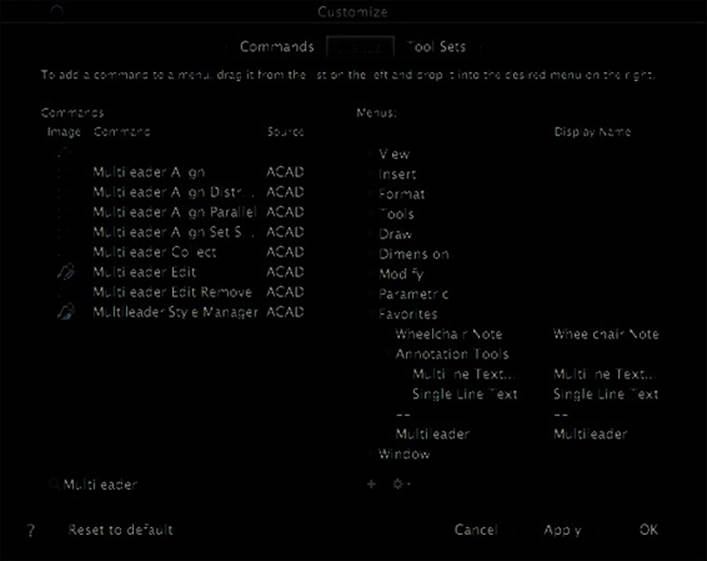
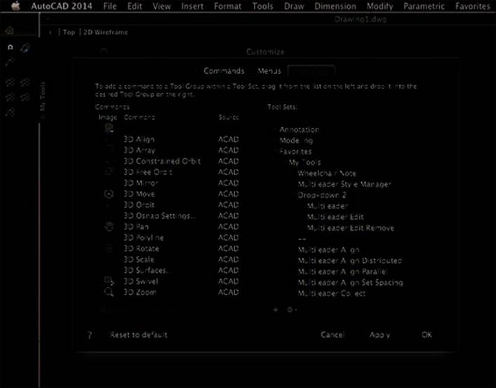
The Customize dialog box, shown in Figure 6.1, is the tool that you will need to become familiar with if you plan to customize the AutoCAD user interface. The Customize dialog box is a simpler interface to learn and use than its Windows counterpart, the Customize User Interface (CUI) Editor. The Customize dialog box in AutoCAD on Mac OS is similar to the Customize dialog box that was in AutoCAD on Windows prior to AutoCAD 2006.
You can display the Customize dialog box using one of the following methods:
◆ Click Tools ➢ Customize ➢ Interface (CUI).
◆ At the command prompt, type cui and press Enter.
When the Customize dialog box is displayed, notice the three tabs along the top. Each of
these tabs allows you to perform a specifi c task related to customizing the user interface. The three tabs in the Customize dialog box are as follows:
Commands Tab Use the Commands tab to create, modify, and remove the commands that can be placed on a toolset to create a button or a pull-down menu to create a menu item.
Menus Tab Use the Menus tab to create, modify, remove, and organize the pull-down menus that are displayed on the menu bar in the user interface. You can add or remove commands to or from a pull-down menu, as well as create submenus and insert separators to
organize similar commands.
Tool Sets Tab Use the Tool Sets tab to create, modify, remove, and organize the toolsets that are displayed as part of the Tool Sets palette. You add or remove commands to or from a tool
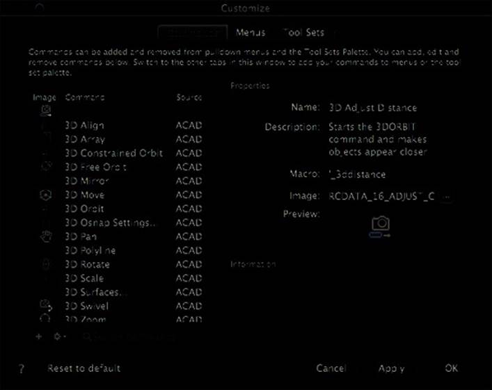
group that’s used to display commands on a toolset. Drop-downs can also be used to orga-
nize similar commands.
NOTE Click the Reset To Defaults button to reset the CUI fi les to their original installed state.
When you do so, all customization to the pull-down menus and toolsets will be removed, along with any new commands or changes to existing commands that you might have made.
Figure 6.1
You create and
modify user-
interface ele-
ments by using
the Customize
dialog box.
Creating Commands and Defi ning Command Macros
Commands are the primary component of an element in the AutoCAD user interface, and they
are created on the Commands tab of the Customize dialog box. The properties of a command
in a CUI fi le defi ne the sequence of AutoCAD commands and options that should be executed when the command is used, as well as how that command should appear on a user-interface element. The sequence of AutoCAD commands and options that a command passes to AutoCAD is
known as a macro. The macro is the most signifi cant property of a command in a CUI fi le.
Understanding the Basics of a Command Macro
A command macro defi nes the input that should be sent to the AutoCAD command prompt
when a user-interface element is used; as with the standard command macros that come with AutoCAD, you can see that you do not need to start and complete a command as part of a command macro. You can start a command with one macro and then click another user-interface
element to send an expected value to the active command. For example, one macro might start
a custom AutoLISP® routine that prompts you for a bolt or window size; instead of typing a size each time, you could use a second macro to pass a value to the routine.
For the most part, a command macro is similar to the input that you enter at the command
prompt to start and complete an AutoCAD command, but it can also contain special characters that control its execution. For example, the following might be what you normally would do to draw a circle with a diameter of 1/8”:
Command: CIRCLE
Specify center point for circle or [3P/2P/Ttr (tan tan radius)]: Specify a point
with the pointing device
Specify radius of circle or [Diameter] <0.1875>: d
Specify diameter of circle <0.3750>: 0.125
A command macro performing the same task and using the same input might look some-
thing like this:
^C^C._circle;\_d;0.125;
As you can see, I used fi ve different special characters in the example macro that were not present as part of the original input entered at the command prompt: ^ (caret), . (period), _
(underscore), ; (semicolon), and \ (backslash). Table 6.1 explains the signifi cance of each character used in the example macro.
Table 6.1:
Macro components used in the circle example
Macro
Component
Description
^C^C
Simulates the pressing of the Esc key twice.
._circle
Passes the circle command to the command prompt.
;
Simulates the pressing of the Enter key to start the circle command. (Could also be a
single space in the macro.)
\
Pauses for the user to specify the center point of the circle.
_d
Indicates that the Diameter option of the circle command will be used.
;
Simulates the pressing of the Enter key to accept the Diameter option.
0.125
Specifi es the value for the Diameter option.
;
Simulates the pressing of the Enter key to accept the Diameter value. Since this is the last expected value, the circle command ends too.
Table 6.2 lists the most common special characters used in a command macro.
Table 6.2:
Special characters that can be used in macros
Special
character
Description
^C
Equivalent to pressing Esc.
;
Equivalent to pressing Enter.
[blank space]
Equivalent to pressing Enter or spacebar based on the expected input of the
current prompt.
\
Allows the user to provide input.
.
Accesses an AutoCAD command’s standard defi nition even when a command
might have been undefi ned with the undefine command.
_
Instructs AutoCAD to use the global command name or option value instead of
the localized name or value provided. Th
is allows the macro to function as
expected when used with a diff erent language of the AutoCAD release.
*
Repeats the AutoCAD command after the asterisk character until the user can-
cels the command.
Example macro from the Point, Multiple Point command in the menugroup
.cui fi le:
*^C^C_point
$M=
Indicates the start of a DIESEL expression.
Example expression from the UCS Icon, On command in the menugroup.cui
fi le:
$M=$(if,$(and,$(getvar,ucsicon),1),^C^C_ucsicon _off,^C^C_
ucsicon _on)
NOTE You can learn about other special and control characters that can be used in a command macro by searching the AutoCAD Help system using the keywords characters in macros.
The next example walks you through the process of converting input entered at the com-
mand prompt into a command macro. You will make a layer, set that layer as current, and then add a multiline text (MText) object.
1. At the command prompt, type -layer and press Enter.
2. At the Enter an option prompt, type m and press Enter.
3. At the Enter name for new layer (becomes the current layer) <0>: prompt, type Notes and press Enter.
4. At the Enter an option prompt, type c and press Enter.
5. At the New color [Truecolor/COlorbook]: prompt, type 8 and press Enter.
6. At the Enter name list of layer(s) for color 8 <Notes>: prompt, press Enter.
7. At the Enter an option prompt, press Enter.
8. At the command prompt, type -mtext and press Enter.
9. At the Specify first corner: prompt, specify a point in the drawing area.
10. At the Specify opposite corner or [Height/Justify/Line spacing/Rotation/
Style/Width/Columns]: prompt, type j and press Enter.
11. At the Enter justification [TL/TC/TR/ML/MC/MR/BL/BC/BR] <TL>: prompt, type tl and press Enter.
12. At the Specify opposite corner or [Height/Justify/Line spacing/Rotation/
Style/Width/Columns]: prompt, type h and press Enter.
13. At the Specify height <0.2000>: prompt, type 0.25 and press Enter.
14. At the Specify opposite corner or [Height/Justify/Line spacing/Rotation/
Style/Width/Columns]: prompt, type r and press Enter.
15. At the Specify rotation angle <0>: prompt, type 0 and press Enter.
16. At the Specify opposite corner or [Height/Justify/Line spacing/Rotation/
Style/Width/Columns]: prompt, type w and press Enter.
17. At the Specify width: prompt, type 7.5 and press Enter.
18. At the MText: prompt, type NOTE: ADA requires a minimum turn radius of and press Enter.
19. At the MText: prompt, type 60" (1525mm) for wheelchairs. and press Enter.
20. Press Enter again to end the mtext command.
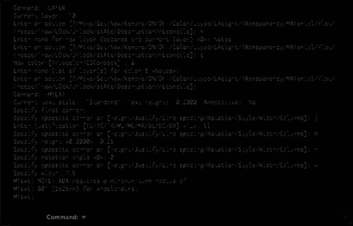
21. Press the FN-F2 key combination to expand the command-line history.
22. In the History area, select the command prompts that were displayed and the input that you entered (see Figure 6.2). Secondary-click (right-click or two-fi nger-click) and click Copy.
23. In the Mac OS Finder, click Go ➢ Applications. In the Finder window, double-click TextEdit.
24. In TextEdit, click in the editor window and press Command-V to paste the copied text from the command-line history.
25. From the pasted text, remove the two informational lines Current layer: and Current text style: and their values.
26. Replace the Specify first corner: prompt with a \ (single backslash character).
27. Remove all the other prompts before the input you entered.
28. After each line, with the exception of the line that contains the backslash, add a ; (semicolon). After this and the previous three steps you should have the following
left in TextEdit.
-layer;
m;
Notes;
c;
8;
;
;
-mtext;
\
j;
tl;
h;
0.25;
r;
0;
w;
7.5;
NOTE: ADA requires a minimum turn radius of;
60" (1525mm) diameter for wheelchairs.;
;
Figure 6.2
Command-line
history of the
input you previ-
ously entered
29. Enter ^C^C before the fi rst line to make sure no other command is active when the macro is used.
30. Place the cursor at the end of each line and press Delete to move all input to a single line.
Your fi nished macro should look like this:
^C^C-layer;m;Notes;c;8;;;-mtext;\j;tl;h;0.25;r;0;w;7.5;NOTE: ↵
ADA requires a minimum turn radius of;60" (1525mm) for wheelchairs.;;
31. Do not close TextEdit, as you will use the macro you created in the next section to create a command for use in the user interface.
TIP Add ._ in front of each command name and an _ (underscore) in front of the values that represent an option name. Th
is will ensure your macro works correctly if a command is undefi ned
or the command macro is used on a non-English AutoCAD release.
Creating and Modifying Commands
Now that you understand how to defi ne a command macro, you can create a command that will allow you to use the macro from the AutoCAD user interface. Commands are created from the Commands tab of the Customize dialog box. In addition to creating new commands, you can
locate and modify existing ones.
The following steps show how to create a command for the wheelchair note macro that you
created in the previous section. If you did not complete the previous exercise, you can open the NoteMacro.txt fi le available for download from this book’s web page at www.sybex.com/go/
autocadcustomization.
1. Click Tools ➢ Customize ➢ Interface (CUI) (or at the command prompt, type cui and press Enter).
2. When the Customize dialog box opens, on the Commands tab under the Command list, click the + (plus sign) to create a new command.
3. In the Properties section, type Wheelchair Note in the Name fi eld. The Name fi eld is used to identify the command in the Command list and is part of the tooltip that is displayed when the cursor is over the command if placed in a tool group as part of a toolset.
4. In the Macro fi eld, type the macro that you created in the previous exercise or copy/paste the contents of the NoteMacro.txt fi le into the text box. The macro defi nes the actions that AutoCAD will perform when the command is used from the user interface.
5. Optionally, in the Description fi eld type ADA Wheelchair minimum radius note. The text entered in this fi eld helps to describe what the command is used for and is part of the tooltip that is displayed when the cursor is over the command when placed on a toolset.
6. Click Apply to save the changes made to the new command’s properties (see Figure 6.3).
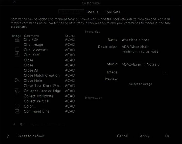
Figure 6.3
Th
e properties
of the completed
command
A command can be edited by selecting it from the Command list and then making changes
to it in the Properties section, just as you did when you created the new command.
Assigning an Image to a Command
While using images with your commands is optional, you should consider adding an image to each of the commands that you create using the Customize dialog box to provide the most fl exibility as to where your commands are used in the user interface. There is no internal image editor in AutoCAD for Mac, so you will need to use an external application to create the images.
Here are the basic requirements:
◆ Images should be 16 × 16 pixels in size; the program will scale them up as needed. Using a higher resolution such as 32 × 32 will look better on higher-resolution displays.
◆ Images can be of the ICO, ICNS, PNG, JPEG, TIFF, BMP, RLE, or DIB fi le formats.
The following steps show how to assign a custom image to the Wheelchair Note command
that you created in the previous section:
1. Display the Customize dialog box if it is not currently open. Click Tools ➢ Customize ➢
Interface (CUI).
2. In the Customize dialog box, on the Commands tab select the Wheelchair Note command. The Command list is sorted alphabetically; you can type wheelchair in the Search Commands text box to help locate the command faster.
3. Under the Properties section, click the ellipsis […] button to the right of the Image fi eld.
4. In the Select An Image File dialog box, browse to the fi les that you downloaded from the book’s web page and select the fi le named WheelchairNote.bmp. Click Open.
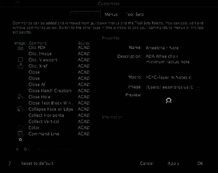
5. Click Apply to save the changes to the command. The Customize dialog box and the Wheelchair Note command should now look like Figure 6.4.
Figure 6.4
Wheelchair com-
mand with the
custom icon
NOTE I recommend that you store your custom images in the location specifi ed by the Custom Icon Files node under Customization Files in the Application Preferences dialog box (options command).
Customizing User-Interface Elements
Out of the box, the AutoCAD user interface is designed for everyone, but not for any specifi c industry or any one single company’s workfl ow. You can add new elements that execute command macros and custom applications you create, remove those that you do not use, or reorganize those that you use frequently to make them easier to access.
The following elements of the user interface can be created and edited with the Customize dialog box:
◆ Pull-down menus
◆ Toolsets and groups; Tool Sets palette
Pull-Down Menus
The menu bar is an area found along the top of the screen and displays a series of menus—also referred to as pull-down menus—related to the active application. You click one of the labels on the menu bar to display the associated pull-down menu. When the pull-down menu is displayed, you click items to start an associated command macro. A pull-down menu can contain separators and submenus to group related commands together. The right side of the menu bar can contain additional items that are not controlled by the active application but are related to systemwide settings, such as the clock or battery level; none of these items can be customized.
Pull-down menus contain the commands defi ned on the Commands tab of the Customize
dialog box. The command macros that you defi ne can use DIESEL (Direct Interpretively
Evaluated String Expression Language) to make decisions with conditional statements, and you can also use DIESEL as part of the menu item’s name after you add a command to the pull-down menu to display a check box next to a menu item. For information on what DIESEL is and how to use it, refer to the AutoCAD Help system.
The following exercise shows how to create a new pull-down menu, add multiple commands
to it, and organize the commands with a separator and submenu:
1. Display the Customize dialog box if it is not currently open. Click Tools ➢ Customize ➢ Interface (CUI).
2. When the Customize dialog box opens, click the Menus tab.
3. On the Menus tab, in the Menus list on the right side, select Parametric. This item represents the Parametric pull-down menu that appears on the menu bar.
4. Click the + (plus sign) button ➢ Add Menu to create a new pull-down menu after the Parametric pull-down menu. Once added, you can drag a pull-down menu in the Menus
list to change its display order on the menu bar.
5. In the in-place editor, type Favorites for the name of the new pull-down menu and press Enter.
6. In the Commands list, locate and add the Wheelchair Note command to the Favorites pull-down menu. Type wheelchair in the Search Command text box. Click and drag the Wheelchair Note command to the Favorites pull-down menu under the Menus list. When
the cursor is over Favorites, release the mouse button.
NOTE Once a command is added to the pull-down menu, you can change its display name by changing the Display Name fi eld in the Menus list. Th
is is the fi eld you need to edit if you want
to include a DIESEL string to display a check mark next to a menu item, similar to the items on the Palettes submenu on the Tools pull-down menu when a palette is displayed.
7. Click the arrow (disclosure triangle) next to the Favorites pull-down menu to expand it.
8. Select the Wheelchair Note command that you added, and then click the + (plus sign) button ➢ Add Sub-menu to create a new submenu below the Wheelchair Note command.
In the in-place editor, type Annotation Tools for the name of the new submenu and press Enter.
9. In the Commands list, locate and add the Multiline Text and Single Line Text commands to the Annotation Tools submenu. Type line text in the Search Command text box to
make it easier to fi nd the two commands.
10. In the Menus list, select the Wheelchair Note command, and secondary-click (right-click or two-fi nger-click) over the command. Click Insert Separator.
11. Click and drag the Annotation Tools submenu above the separator.
12. In the Command list, locate and add the Multileader command below the separator. Type multileader in the Search Command text box to make it easier to fi nd the command.
Figure 6.5 shows what the completed pull-down menu should look like under the
Menus list.
Figure 6.5
Structure of the
Favorites pull-
down menu in the
Customize dialog
box
13. Click OK to save the new pull-down menu.
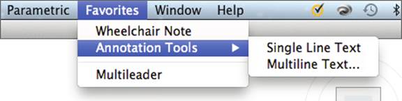
14. On the menu bar, click Favorites. Figure 6.6 shows what the Favorites pull-down menu should look like on the menu bar. Click the Wheelchair Note item and then specify a
point in the drawing to test the command and its macro. Figure 6.7 shows the results of
the command macro. Continue to test the other menu items and submenu of the pull-
down menu.
Figure 6.6
Favorites pull-
down menu on
the menu bar

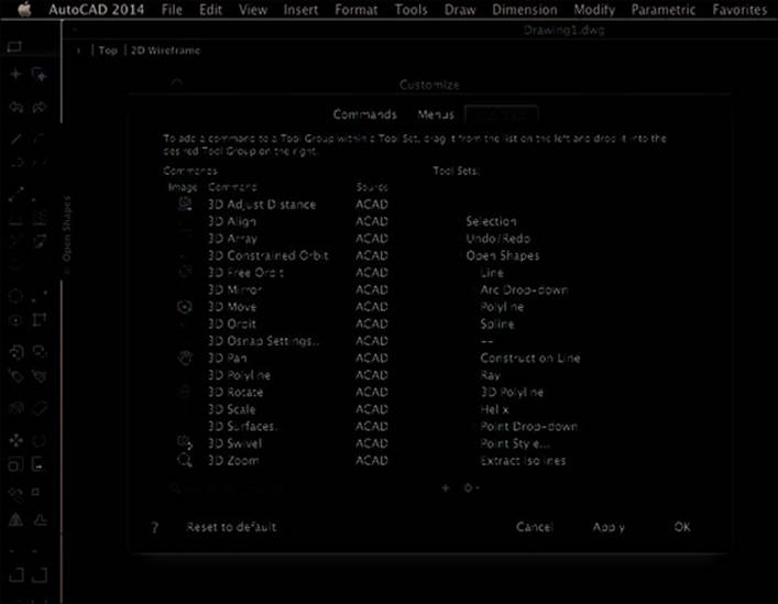
Figure 6.7
Th
e results
of using the
Wheelchair Note
command
Toolsets
The Tool Sets palette is the visual user interface on AutoCAD for Mac that allows you to start a command. It is a cross between toolbars and the ribbon found in AutoCAD for Windows or
Microsoft Offi ce 2013. Near the top of the Tool Sets palette is the Tool Set button, which allows you to switch between the currently displayed toolset and other available toolsets. Three default toolsets come with the program, and these are based on the tasks of 2D drafting, 3D modeling, and annotating a drawing.
Each toolset can be made up of one or more tool groups, which allow you to group similar
commands. Tool groups can be in one of two different display states: normal or expanded.
When defi ning a tool group, you can specify which commands are displayed in the normal state of the tool group by placing them above a separator. Those added below the separator are displayed when the tool group is expanded.
If a tool group contains commands below the separator, an arrow is displayed along the left or right side of the tool group when it is displayed on the Tool Sets palette. Clicking the arrow expands the group so you can use the commands that are not displayed by default. When a group is expanded, it can be locked to remain expanded until you unlock it. Drop-downs can be added to a tool group to further organize related commands. Figure 6.8 shows the Open Shapes tool group in the Drafting toolset on the Tool Sets palette and how it is defi ned in the Customize dialog box.
Figure 6.8
Structure of the
Open Shapes tool
group
The following explains how to create a new toolset named Favorites and a group named My
Tools. Once the My Tools group is created, you will add several commands to it, including the Wheelchair Note command that you created earlier in this chapter.
1. Display the Customize dialog box if it is not currently open. Click Tools ➢ Customize ➢ Interface (CUI).
2. When the Customize dialog box opens, click the Tool Sets tab.
3. On the Tool Sets tab, in the Tool Sets list on the right, select Modeling. This item represents the Modeling toolset that is accessible from the Tool Sets palette.
4. Click the + (plus sign) button ➢ Add Tool Set to create a new toolset. Once added, you can drag a toolset in the Tool Sets list to change its order on the menu that is displayed when the Tool Sets button is clicked at the top of the Tool Sets palette.
5. In the in-place editor, type Favorites for the name of the new toolset and press Enter.
6. Click the arrow (disclosure triangle) next to the Favorites toolset.
7. Click the default tool group under the Favorites toolset, and then click the tool group a second time to display the in-place editor to rename the tool group. Type My Tools for the name of the tool group and press Enter. Click the + (plus sign) button ➢ Add Tool
Group to add other tool groups if desired.
8. Click the arrow (disclosure triangle) next to the My Tools tool group.
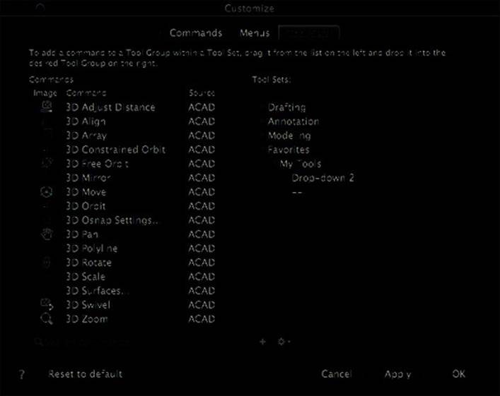
9. Select the My Tools tool group and click the + (plus sign) button ➢ Add Drop-Down to add a drop-down menu to the tool group. Your toolset and tool group should now look
like Figure 6.9.
Figure 6.9
Structure for the
new Favorites
toolset and the
My Tools tool
group
10. Locate the Wheelchair Note command in the Command list and add it to the My Tools tool group above the new drop-down. Type Wheelchair in the Search Command text
box. Click and drag the Wheelchair Note command to the My Tools tool group. When
the cursor is below the My Tools tool group and above the drop-down menu, release the
mouse button.
11. In the Command list, locate and add the Multileader, Multileader Edit, and Multileader Edit Remove commands to the drop-down. Remember, you can use the Search Command
text box to fi lter the Command list.
12. Add the Multileader Style Manager command between the Wheelchair Note and
drop-down.
13. Add the other fi ve multileader-related commands under the separator, which is represented by the – – item under the My Tools tool group.
14. Create a new tool group and add some of your favorite commands, if you want. Figure 6.10 shows the new toolset and group in the Customize dialog box.
Figure 6.10
Tool Set Button
Completed
Favorites toolset
and My Tools tool
group
15. Click OK to save the new toolset.
16. On the Tool Sets palette, click the Tool Sets button near the top of the palette and click Favorites. Test the tools on the tool group and expand the tool group to see the commands placed below the separator.
NOTE Secondary-click (right-click or two-fi nger-click) over a toolset in the Tool Sets list of the Customize dialog box to assign an image to it. Th
is image is displayed on the toolset menu
when the Tool Sets button is clicked.
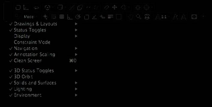
Controlling the Tools on the Status Bar
AutoCAD displays a status bar that allows you to access 2D-drafting and 3D-modeling aids, switch layouts, and set the scale to use for annotation scaling and the current viewport, among other options. While you can control which tools are displayed, you can’t create and place new tools on the status bar. Even though you can’t add new tools, it can be helpful to hide those that you do not use, such as, say, Polar Tracking and ViewCube®. You can also choose to hide the status bar by clicking Tools ➢ Palettes ➢ Status Bar or using the statusbar system variable.
Unlike other user interface elements, the settings that control the display of the tools on the status bar are not stored in the main customization (CUI) fi le; instead, they are stored with the program’s property list (Plist) fi les. When controlling which tools are displayed on the status bar, you use the following options:
3D Status Bar Disclosure Triangle Click the Show/Hide 3D Status Bar disclosure triangle located on the right side of the status bar to show or hide the 3D-related tools. The 3D-related tools are displayed above the standard tools on the status bar.
Status Bar Context Menu The status bar’s context menu (see Figure 6.11) allows you to toggle which drafting aids, layout, annotation scaling, viewport, and other available tools are displayed or hidden on the status bar. Which items are displayed on the menu is dependent on whether or not the 3D status bar is shown. Secondary-click (right-click or two-fi nger-click) in an empty area of the status bar to display its context menu.
Figure 6.11
Controlling the
display of tools on
the status bar
All materials on the site are licensed Creative Commons Attribution-Sharealike 3.0 Unported CC BY-SA 3.0 & GNU Free Documentation License (GFDL)
If you are the copyright holder of any material contained on our site and intend to remove it, please contact our site administrator for approval.
© 2016-2026 All site design rights belong to S.Y.A.