Software Engineering: A Methodical Approach (2014)
PART C. Software Design
Chapter 12. Operations Design
This chapter discusses operations design as an integral part of the software design experience. The chapter proceeds under the following captions:
· Introduction
· Categorization of Operations
· Essentials of Operations Design
· Informal Methods for Specifying Operation Requirements
· Formal Specification
· Summary and Concluding Remarks
12.1 Introduction
Whether the functional approach or the object-oriented approach is employed, ultimately, software systems will necessarily have operations. An important aspect of software engineering is the preparation of operation specifications for the operations of a system. Hence, operations design forms a very important component of software design.
The spin-off from operations design is a set of operation specifications: each operation has an operation specification (commonly abbreviated as operation spec), which can be pulled by a programmer and used in developing the required operation (program). The more thorough the spec, the easier is the required programming effort.
In OOD, the operations are implementation of the verbs that link objects and allow communication between these objects. A common practice is to make the operations singular (monolithic) in nature, thus further simplifying the subsequent development and maintenance processes. Further, complex operations are made to employ the services of other (simpler) operations, thus promoting code reuse and efficiency.
In the OOD paradigm, we refer to the analysis of operations (and other related issues) as object behavior analysis (OBA). You will recall that in chapter 10, we used the corresponding term object structure analysis (OSA) to describe analysis relating to data structures of object types comprising the software system. Take some time to review the OO modeling pyramid (Figure 7.11) of Chapter 7. What you need to remember is that OOD boils down to two things — OSA and OBA.
On the other hand, in FOD, the functions typify (functional) activities in the organization and facilitate management and retrieval of information; verbs may be combined in a single function. This sometimes leads to more complex functions, with a significantly lower level of reusability of code.
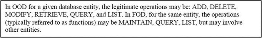
Example 1: For a typical information entity in a software system, the operations may be defined as follows:
12.2 Categorization of Operations
Categorization of the operations is a useful strategy, particularly during subsequent software development:
· Some operations will be more complex than others, and will therefore need longer development time.
· Also, by knowing about the relative complexity of operations making up a system, a project manager can make prudent decisions about work schedule.
· Some operations will be more crucial to the overall software product than others; if this information is known, important prioritization decisions can be made.
Thus, by carefully categorizing operations the software designer can significantly contribute to the success of subsequent software development and maintenance. Figure 12-1 provides a four-step approach to categorizing operations.
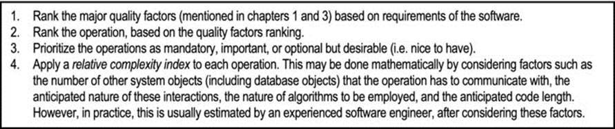
Figure 12-1. Categorizing Operations
While the first two steps of Figure 12-1 may be considered optional, the latter two are essential, as they help in guiding decisions about the project during the development phase.
12.3 Essentials of Operations Design
Each operation must be assigned a unique system (implementation) name. Preferably, these system names should conform to the established naming convention that is in vogue (review chapter 9).
For each operation, the following should be clearly stated: what the operation will do; the inputs and outputs; the algorithm(s) to be implemented; any required validation rules and/or calculation rules. These things are normally provided in an operation specification (often abbreviated as operation spec or op spec).
In the interest of clarity and efficiency, operation specs are usually expressed in a standard format, according to the software development standards of the organization (review chapter 9). Over the years, several formal methods as well as informal methods for software specification have been proposed. The next two sections will summarize some of the commonly used approaches, as well as a pragmatic approach, introduced by the author.
As you proceed, bear in mind that an operation will be implemented by code in a particular programming language. How it is implemented depends on the development environment: In an FO environment, it is typically implemented as a program. In a purely OO environment, the operations may be implemented as a method of a class, a class consisting of several related methods, or a set of related classes. This is also the likely case in a hybrid environment (consisting of an OO user interface superimposed on a relational or object database).
12.4 Informal Methods for Specifying Operation Requirements
Remember, in operations specification, the software engineer is attempting to define and express the requirements of system operations in a manner that promotes comprehension and efficiency, while avoiding the hazard of being ambiguous or too verbose.
In this section, we shall briefly review some traditional approaches to operations specification. We will then look at use of the Warnier-Orr diagram and the UML notation. The section closes with a discussion of a methodology introduced by the author.
12.4.1 Traditional Methods
Traditional informal methods of operations specification include program flowcharting, the use of IPO charts, decision techniques, and pseudo-coding (review chapter 5). The main advantages of these approaches are:
· Visual aid (in the case of IPO chart and program flow chart)
· Flexibility and creativity in treating unanticipated or complex situations
However, these approaches have inherent flaws, some of which are stated below:
· None of these approaches lends itself to comprehensive coverage of all the requirements of operations of a software product. To illustrate, a flowchart does not readily provide information about the inputs to and outputs from an operation as well as an IPO chart. An IPO chart does not represent logical decisions as well as a flowchart or decision table. Neither does a pseudo-code.
· Pseudo-codes and flowcharts can be difficult to maintain, especially for a large, complex system.
· The use of pseudo-code does not facilitate easy analysis; it does not avoid the possibility for ambiguity, since there is no established standard vocabulary; neither does it facilitate easy automation.
In view of the foregoing, the IPO chart of Figure 12-2 should illustrate the limitations of the technique. The figure shows an IPO chart for an operation that facilitates addition, modification, or deletion of employee records in a human resource management system (HRMS), or some other system requiring employee information. Traditionally, operations that provide such functionalities (addition, update, and deletion) were called MAINTAIN operations, and appeared frequently in software systems designed in the FO paradigm.
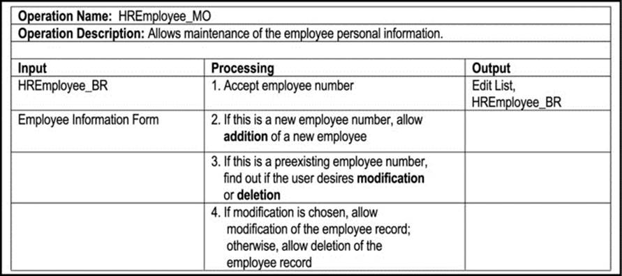
Figure 12-2. IPO Chart for a MAINTAIN Operation
12.4.2 Warnier Orr Diagram
In the Warnier-Orr approach, the operation is consistently broken down into constituent activities, in a hierarchical manner. Component activities are numbered in a manner similar to the sections of the chapters of this book. The basic idea is as shown in Figure 12-3.
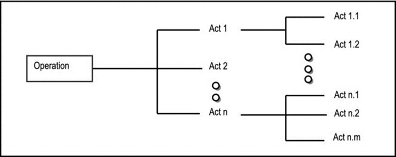
Figure 12-3. Illustration the Warnier-Orr Method
A Warnier-Orr diagram provides two main advantages:
· It shows the relationships among activities of an operation.
· If activities are logically arranged it can replace the flowchart/pseudo-code.
Disadvantages of the Warnier-Orr Diagram Are
· It does not explicitly show inputs to or outputs from an operation.
· It does not include explicit representation of logical decisions.
· The diagram can grow indefinitely, so that in the absence of a CASE tool that supports the technique, maintaining Warnier-Orr diagrams for system operations could be quite time consuming.
Although the technique might appear to have a function-oriented connotation, it is in fact also applicable in an object-oriented scenario. Figure 12-4 provides an example of a Warnier-Orr diagram for a MAINTAIN operation for employee records. The operation name (HREmployee_MO) is indicated in the first activity box. Still referring to the figure, the item HREmployee_BR may be implemented as an object type in an OO environment, or as a relational table in a relational database that is access by an appropriately constructed user interface (which may very well be based on an OO software development environment). This operation would form part of the user interface.
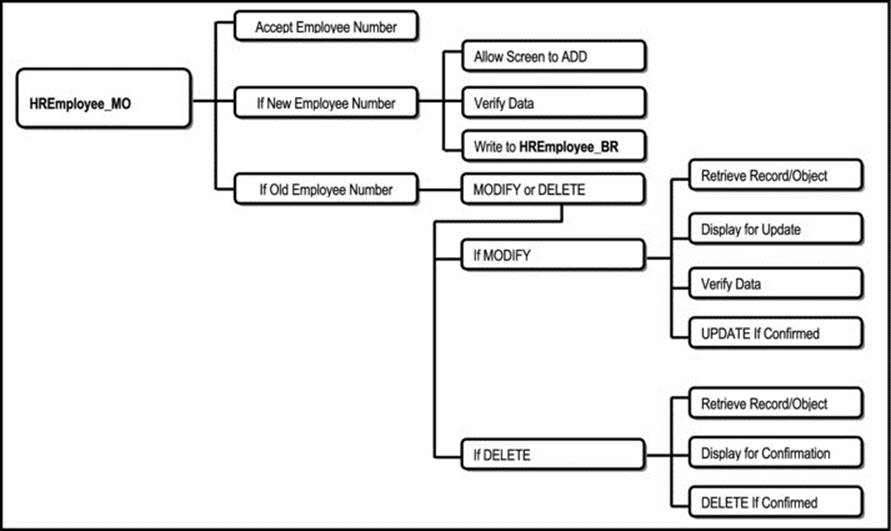
Figure 12-4. Warnier-Orr Diagram for a MAINTAIN Operation
12.4.3 UML Notations for Object Behavior
The unified modeling language (UML) employs a comprehensive set of notations for specifying the behavior of objects when using the object-oriented approach to software design. In conducting OBA, the UML facilitates the following techniques:
· Use-case Diagrams
· State Diagrams
· Activity Diagrams
· Sequence Diagrams and Collaboration Diagrams
State diagrams (also called finite state machines) were discussed in chapter 6. A full discussion of the other techniques is best deferred for your course in OOM. However, appendix 6 provides an overview. Please review figures 10-10 and 10-11 of chapter 10. In those figures, some of the information entities that would be found in the CUAIS project (for a generic college or university) were represented. One such entity (object type) was the Employee. The following figures (Figures 12-5 – 12-8) provide examples of a use-case diagram or a typical Employee object, a state diagram for a typical Employee object, (copied from chapter 6), an activity diagram for creating (i.e. adding) an Employee object, and a collaboration diagram for querying (i.e. inquiring on) an Employee object.
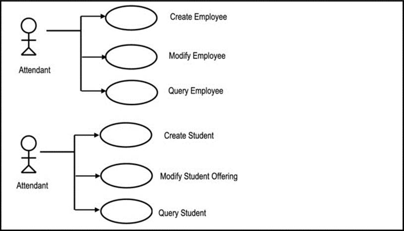
Figure 12-5. Use-case for Employee Processing and Student Processing
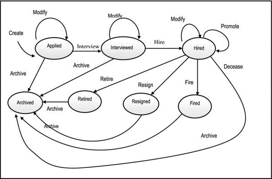
Figure 12-6. State Diagram for Employee Object
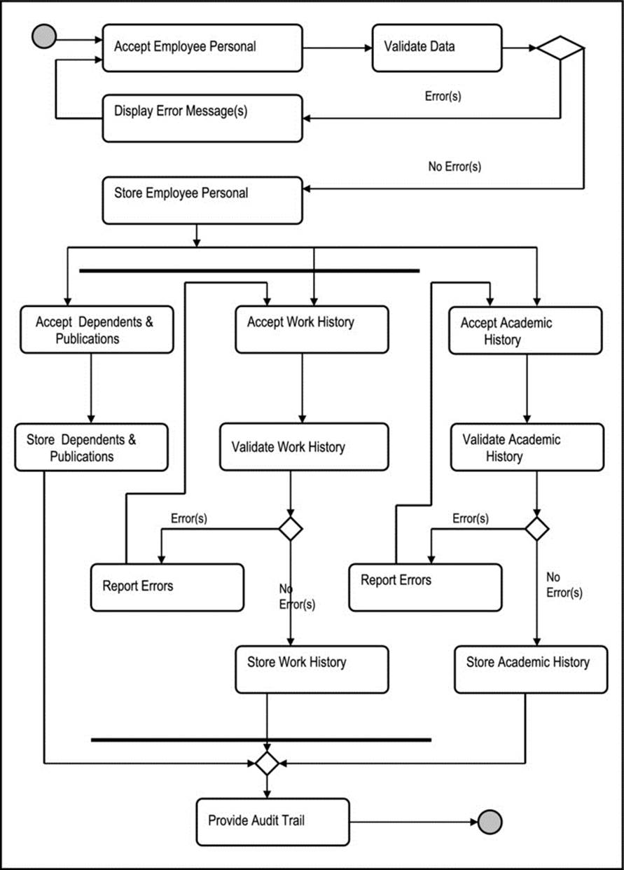
Figure 12-7. Activity Diagram for Adding Employee Information
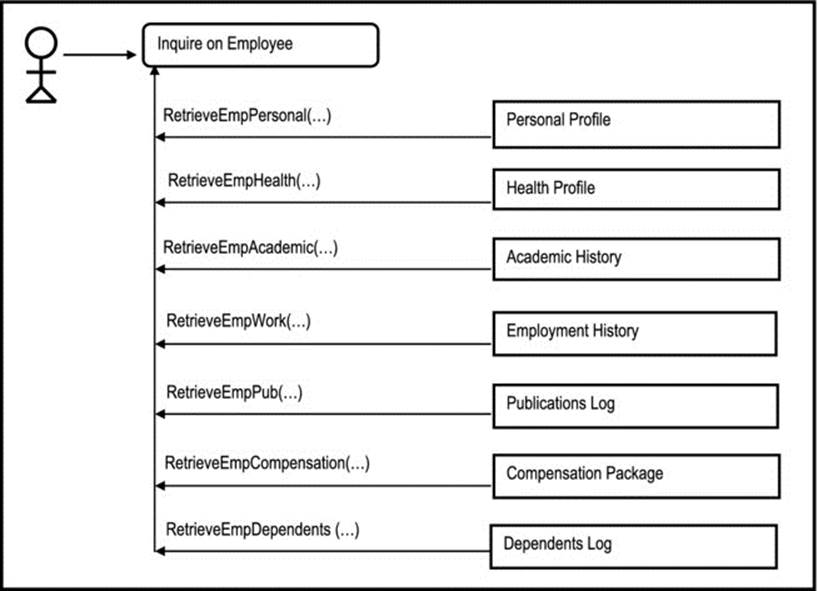
Figure 12-8. Collaboration Diagram for Inquiry on Employee Information
12.4.4 Extended Operation Specification
The extended operation specification (EOS) approach was developed by the current writer, and has been successfully used on various systems designed by him. In this approach the software engineer records important requirements about an operation in such a manner as to offset the disadvantages of the previously discussed methods.
The basic idea is to provide enough detail about the required operation, so that a programmer that pulls the spec should have little or no problem in writing the operation (program). The format recommended is shown in Figure 12-9. Observe that the specification also includes categorization information, which may be used during software development. The technique is applicable to both FOD and OOD.
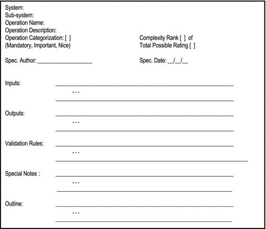
Figure 12-9. Components of the Extended Operation Specification
Note:
1. The required output formats and/or screen formats could be (and are usually) designed and attached.
2. Validation rules are itemized and special notes are itemized.
3. The outline could be in the form of a pseudo-code (as illustrated in the Figures 12-11 – 12-14), a flowcharts, a Warnier-Orr diagram, an IPO Chart, or an activity diagram.
Figure 12-10 provides an excerpt from the object/entity specification grid (O/ESG) of Chapter 10, repeated here for convenience; here, we shall concentrate on the Employee object type (entity). Figures 12-11 – 12-14 provide sample EOSs for an ADD operation, an UPDATE operation, a DELETE operation and an INQUIRE operation respectively.
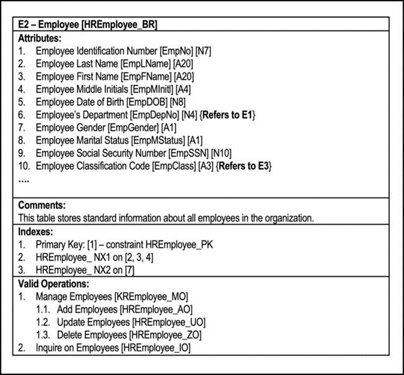
Figure 12-10. Sample Object/Entity Specification Grid for Employee
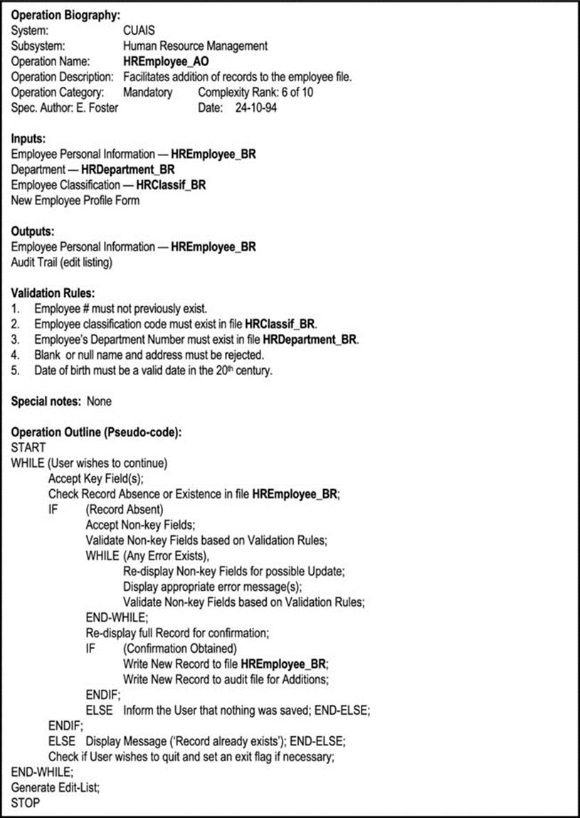
Figure 12-11. Sample EOS for ADD Operation
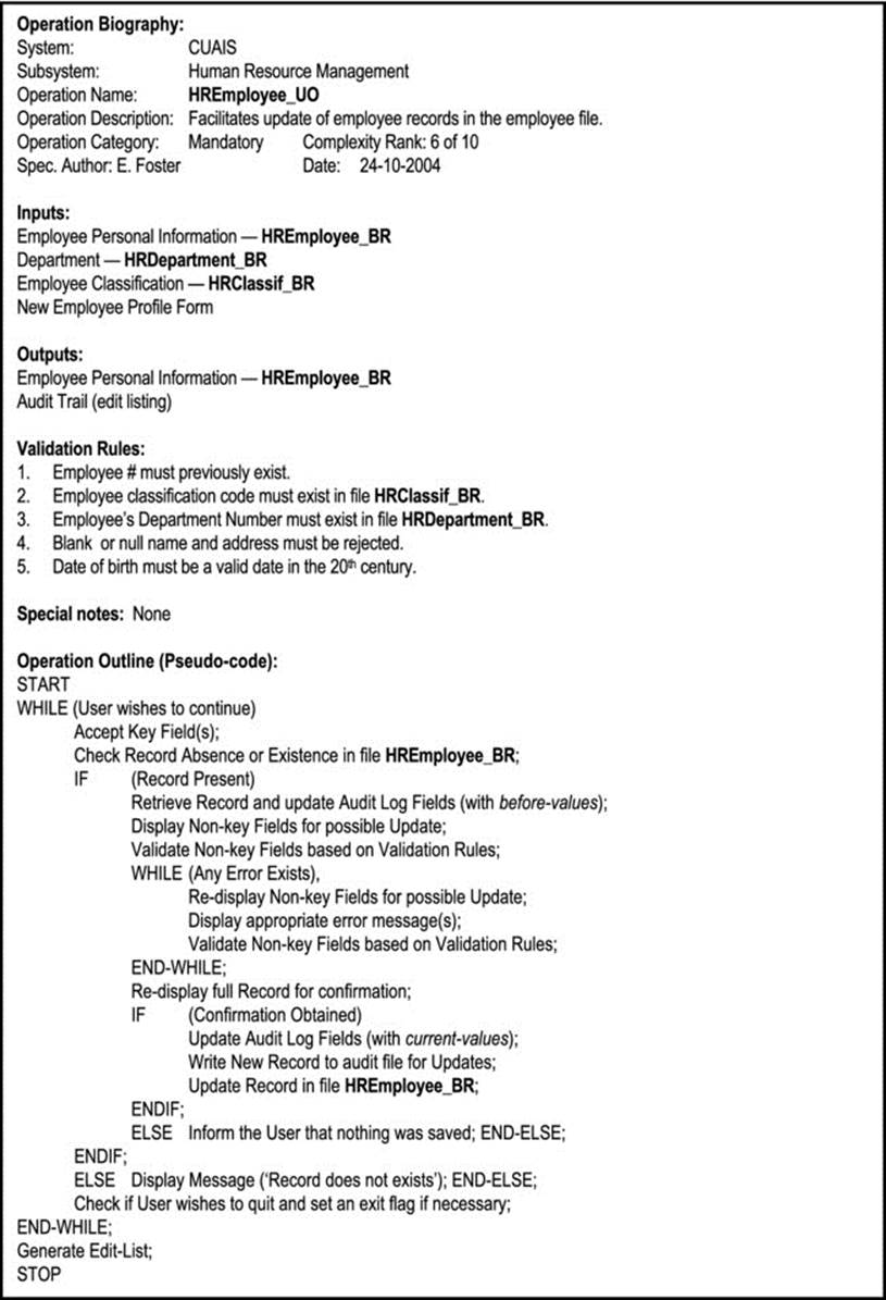
Figure 12-12. Sample EOS for UPDATE Operation
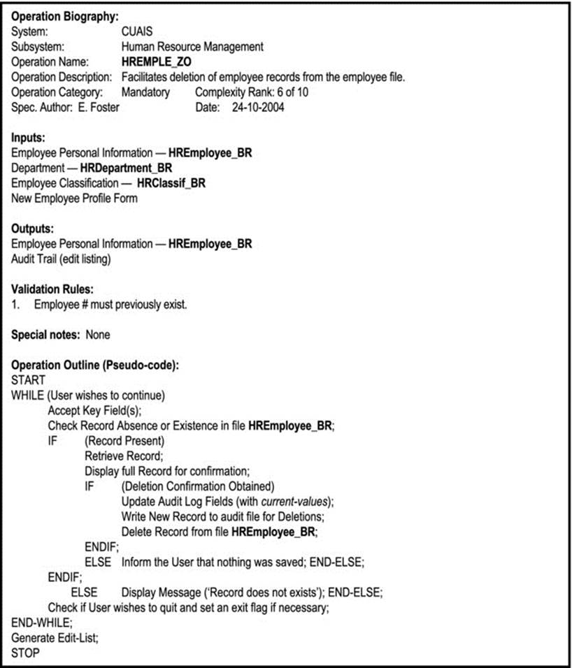
Figure 12-13. Sample EOS for DELETE Operation
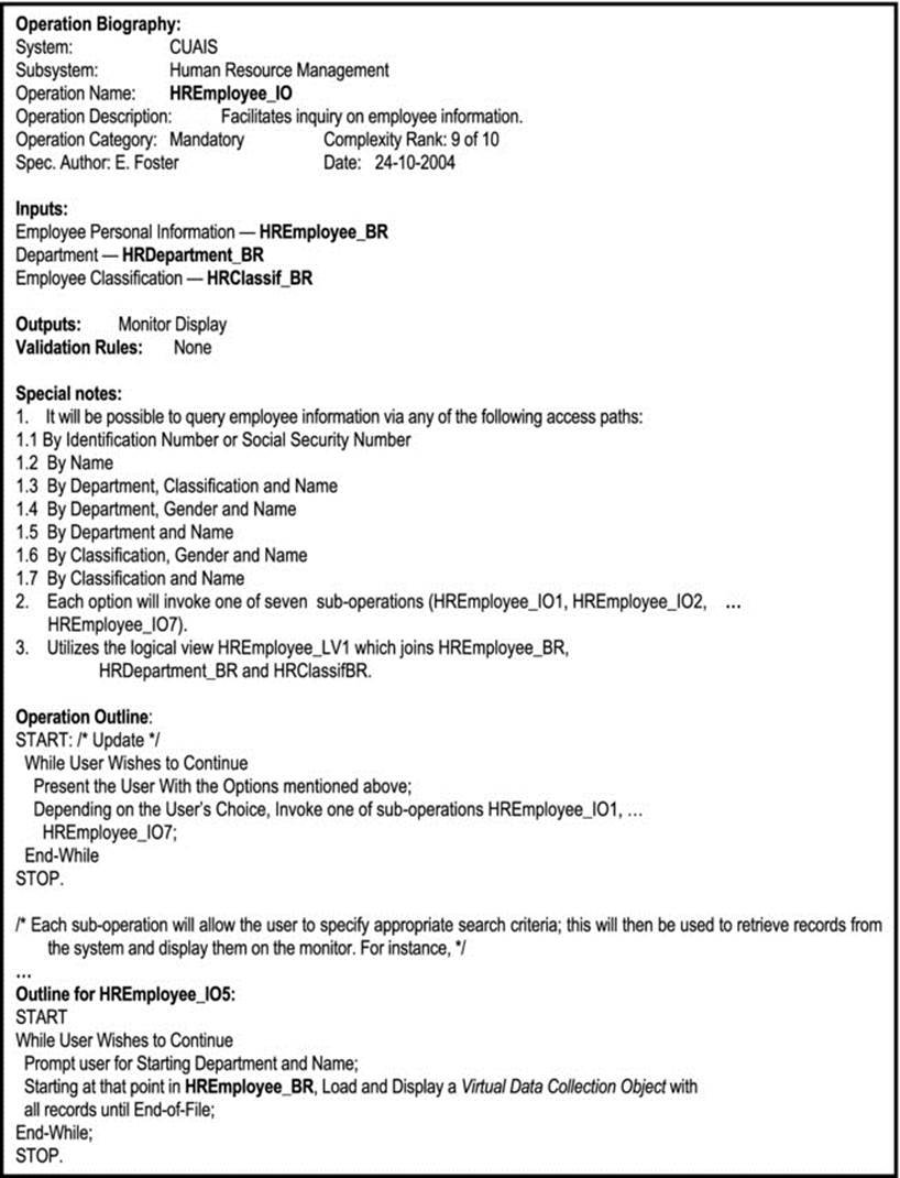
Figure 12-14. Sample EOS for INQUIRE Operation
Three additional points to note from the illustrations (Figures 12-11 – 12-14):
1. The algorithms for adding, modifying and deleting data items (records) have been standardized and can be used for different scenarios. How they are implemented will vary for different software development tools.
2. The term Virtual Data Collection Object, as used in Figure 12-14, refers to any user interface widget that may typically be employed by a RAD or CASE tool (for instance, in Delphi, we could us a DB-Grid or a DB-Image; in Team Developer, we could use a Child-Table).
3. The term logical view has also been introduced in Figure 12-14. A logical view is a virtual database object which stores an access path to data contained in persistent database tables. In the example, we have a join logical view, based on the fact that there is a relationship between E2 (HREmployee_BR) and E1 (HRDepartment_BR) on the one hand, and E2 (HREmployee_BR) and E3 (HRClassif_BR) on the other (see Figure 12-10 and review Figure 10-9 of Chapter 10). You will spend much more time working with logical views in your database systems course.
Among the advantages of EOS are the following:
· It allows the software engineer to pack all the relevant information about an operation into one spec so that development is easy.
· It provides information that allows the project manager to make intelligent work assignments during software development.
· Under the operation outline section, the software engineer has the flexibility of using a program flowchart, a pseudo-code, a Warnier-Orr diagram, or an activity diagram.
· Important information such as I/O requirements, categorizations, etc. can be included in the spec.
· The whole process of specifying an EOS for an operation can be automated by developing a software system for that purpose.
In terms of disadvantages of the EOS, no major drawback of the methodology has been identified so far. However, with time it is anticipated that constructive criticisms will inspire further refinement.
12.5 Formal Specifications
A formal specification of software is a specification that is expressed in a language whose syntax and semantics have been formally defined.
Formal specification methods have been developed and are widely used in software engineering. Several program description languages (PDLs) have been proposed and used in software engineering. Some examples are mentioned below:
· PSL — Problem Statement Language
· Ada PDL
· Z-specifications (pronounced zed specifications)
· Larch Specifications
· B Specifications
· Lotos Specifications
The prediction that by the twenty first century, a significant proportion of software systems would be developed by formal methods has not been realized, due to a number of reasons:
1. Successful informal methods such as structured methodologies and OO methodologies have been on the increase.
2. Market dynamics puts pressure on the software engineering industry to produce software at much faster rates than formal methods would allow.
3. Formal methods are not well suited for some scenarios, e.g. user interface development.
4. Formal methods provide limited scope for quality factors such as scalability and portability. To some extent, maintainability and flexibility are also negatively affected. As you are aware, these are crucial requirements for contemporary software.
One significant advantage of formal methods is that they force precise, unambiguous specification of software. Because of this, formal methods are widely used in areas of software engineering where precision is required. Two examples of such areas are hardware synthesis and compilation. However, to do justice to the field, further exploration of formal specifications is best treated in a course on formal methods.
12.6 Summary and Concluding Remarks
It’s time once more for us to summarize what we have covered in this chapter:
· Operations design is an integral part of the OBA process (assuming the OOD paradigm). The spin-off from operations design is a set of operation specifications: each operation has an operation specification that outlines the blueprint for the operation.
· Categorizing operations is very useful particularly during the development of the software system. Each operating can be categorized by giving consideration to its alignment with quality factors or importance to the software system, the level of importance of the operation, and its relative complexity.
· Each operation spec must have a unique name, followed by unambiguous guidelines that will help a programmer to easily write the actual operation.
· Informal methods of operations specifications include (but are not confined to) the following: traditional methods (program flow charts, pseudo-code, and IPO charts); Warnier-Orr diagrams; UML diagrams (use-case diagrams, state diagrams, activity diagrams, sequence diagrams, and collaboration diagrams); EOS formulations.
· Formal methods of operations specifications include (but are not confined to) PSL, ADA/PDL, Z-specifications, Larch specifications, B specifications and Lotos specifications.
Armed with the software development standards, architectural specification, the database specification, the user interface specification, and the operation specification, you are almost ready to embark on the actual software development with confidence. Bear in mind that if you are using an OO-CASE tool, actual design and development may be merged into one modeling phase, since many of the diagrams may be executable diagrams. Appendix 6 provides additional discussion and illustrations on OBA, and appendix 10 provides several examples of operation specifications (from the Inventory Management System of earlier mention). We still have a few design issues to cover, and these will be discussed in the next chapter.
12.7 Review Questions
1. How important is operations design? Explain how it affects the development of a software system.
2. Outline an approach for categorizing operations comprising a software system.
3. The Student entity would be an important component of the CUAIS project. It contains attributes StudentID, Name, Gender, DateOfBirth, Major, Dept#, among others. Each Student object has a unique identification number. The department (Dept#) to which a student is assigned must previously exist in the Department entity. Also, the student’s major must reside in the AcademicProgram entity. Gender must be male or female and DateOfBirth must be a valid date in the 20th or 21st century.
3a. Propose an O/ESG for the Student entity.
3b. Propose an EOS for the operation to allow addition of valid student records. Your outline may include a Warnier-Orr diagram, a pseudo code, or an activity diagram.
3c. Propose an EOS for an operation to allow users to run interactive query of student information.
3d. Propose a collaboration diagram for interactive query of student information.
4. Examine Figure 12-6 and thoroughly explain all the state transitions and the operations that trigger them.
5. Examine Figure 12-7 and thoroughly explain the behavior of the ADD Employee operation.
6. Examine Figure 12-8 and thoroughly explain it.
7. When is formal specification relevant? Give three examples of formal specification languages.
12.8 References and/or Recommended Reading
[Peters, 2000] Peters, James F. and Witold Pedrycz. Software Engineering: An Engineering Approach. New York, NY: John Wiley & Sons, 2000. See Chapter 5.
[Pfleeger, 2006] Pfleeger, Shari Lawrence. Software Engineering Theory and Practice 3rd ed. Upper Saddle River, NJ: Prentice Hall, 2006. See Chapter 4.
[Schach, 2005] Schach, Stephen R. Object-Oriented and Classical Software Engineering 6th ed. Boston, MA: McGraw-Hill, 2005. See Chapter 16.
[Sommerville, 2006] Sommerville, Ian. Software Engineering 8th ed. Boston, MA: Addison-Wesley, 2006. See Chapter 10.
[Van Vliet, 2000] Van Vliet, Hans. Software Engineering: Principles and Practice. New York, NY: John Wiley & Sons, 2000. See Chapter 15.
All materials on the site are licensed Creative Commons Attribution-Sharealike 3.0 Unported CC BY-SA 3.0 & GNU Free Documentation License (GFDL)
If you are the copyright holder of any material contained on our site and intend to remove it, please contact our site administrator for approval.
© 2016-2026 All site design rights belong to S.Y.A.