Software Engineering: A Methodical Approach (2014)
PART G. Appendices
Appendix 10. Design Specification for a Generic Inventory Management System
This appendix provides excerpts from a sample design specification (DS) for a generic Inventory Management System (IMS) that may be suitable for a small or medium sized organization. The document is a follow-up to the RS of appendix 9, and includes the following:
· System Overview
· Database Specification
· Operations Specification
· User Interface Specification
· Message and Help Specifications
· Summary and Concluding Remarks
A10.1 System Overview
A10.1.1 Problem Definition
See section A8.1 of Appendix 8.
A10.1.2 Proposed Solution
See section A8.2 of Appendix 8.
A10.1.3 System Architecture
The System will have five main components:
· Acquisitions Management Subsystem (Java or Delphi)
· Financial Management Subsystem (Java or Delphi)
· System Controls Subsystem
· Point of Sale Subsystem (POSS)
· Database Backbone (MySQL)
Figure A10-1 provides the information topology chart (ITC) and Figure A10-2 shows the object flow diagram (OFD). Notice that on the ITC there are additional entities added under the Controls Subsystem, compared to the diagram provided in Appendix 9. This represents a refinement of the ITC provided in the requirements specification.
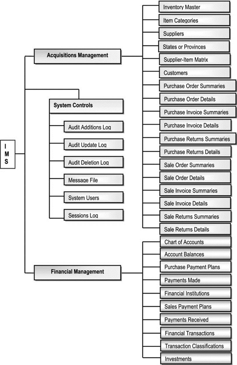
Figure A10-1. IMS Information Topology Chart
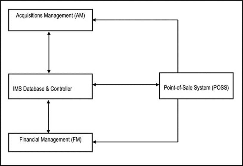
Figure A10-2. IMS Object Flow Diagram
A10.2 Database Specification
The database specification will proceed under the following captions:
· Introduction
· Acquisitions Management Subsystem
· Financial Management Subsystem
· System Controls Subsystem
A10.2.1 Introduction
The database specification of the system will be covered in this section. The methodology employed for database specification is the object/entity specification grid (O/ESG) developed by the current author. Following is a summary of the conventions used:
Each information entity referenced is identified by a reference code and a descriptive name.
· For each entity the attributes (data elements) to be stored are identified.
· The entities as presented, will easily transition into a set of normalized relations in a normalized relational database.
· Data elements that will be implemented as foreign keys, in the normalized relational database, are identified by comment in curly braces, specifying what entity they reference.
· For each attribute, the physical characteristics will be given (as described in the next section); the attributes implementation name will be indicated in square brackets; it will be indicated whether the attribute is a foreign key.
· Indexes (including primary key or candidate keys) to be defined on the entity are indicated.
· For each entity a comment describing the data to be stored is provided. Additionally, the entities implementation name is indicated in square brackets.
· Each operation defined on an entity will be given an implementation name, indicated in square brackets.
Naming of database objects will be very important for the following reasons:
· The database will host several objects. Without a proper naming convention, it will be extremely difficult to keep track of them.
· The naming convention will enable us to easily categorize database objects on sight.
Figure A10-3 provides the object naming convention for the project.
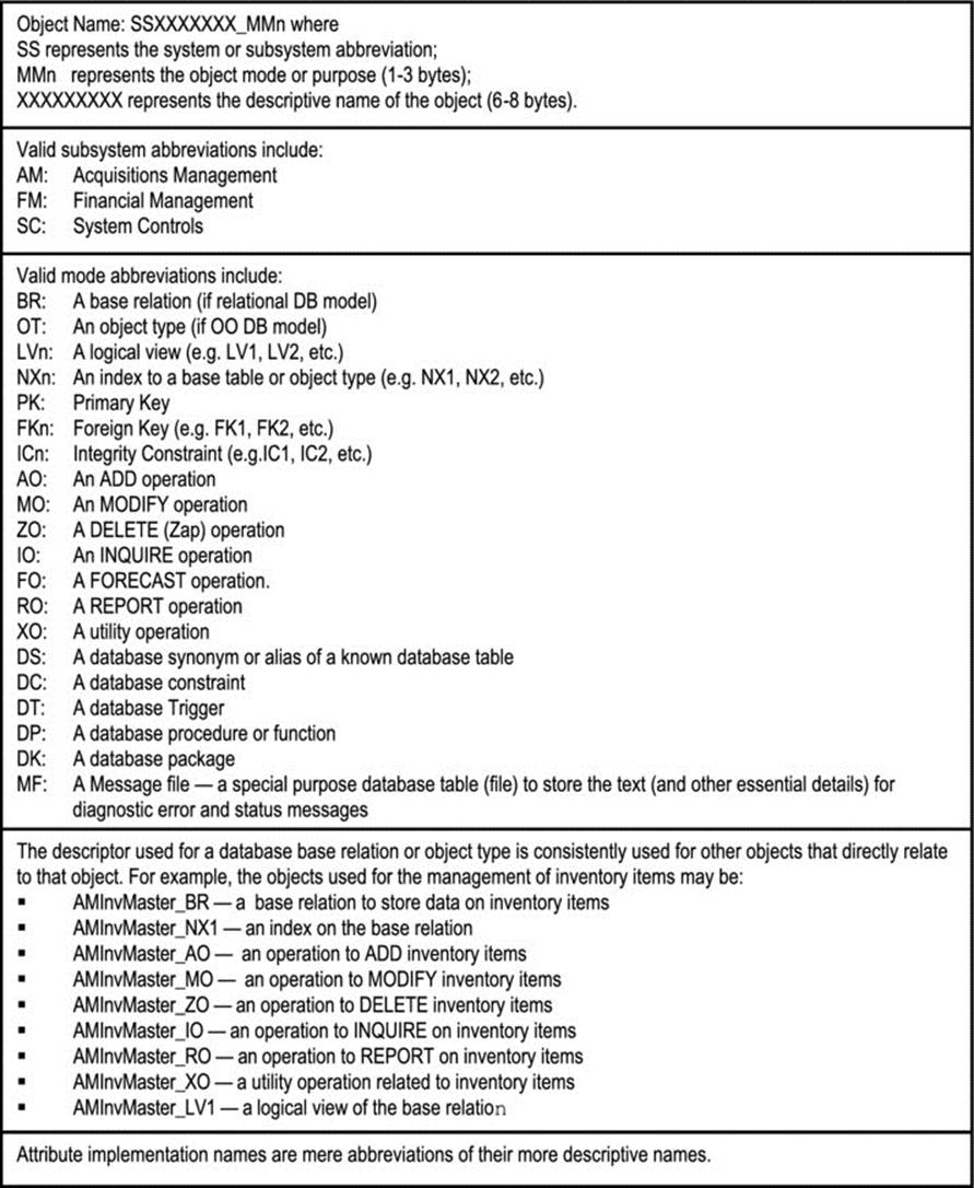
Figure A10-3. Object Naming Conventions
A10.2.2 Acquisitions Management Subsystem
Following is the O/ESG for each information entity comprising this subsystem (Figure A10-4):
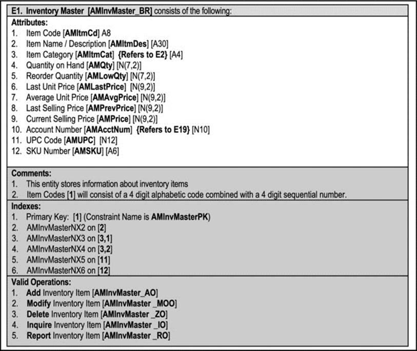
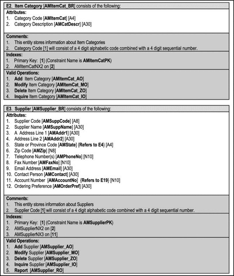
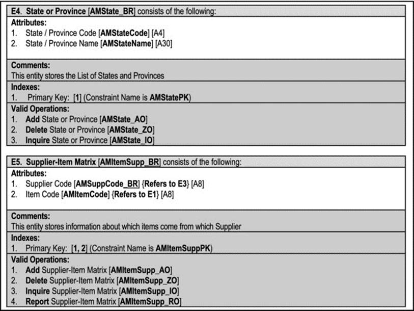
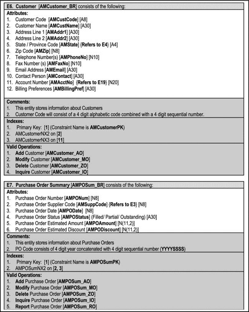
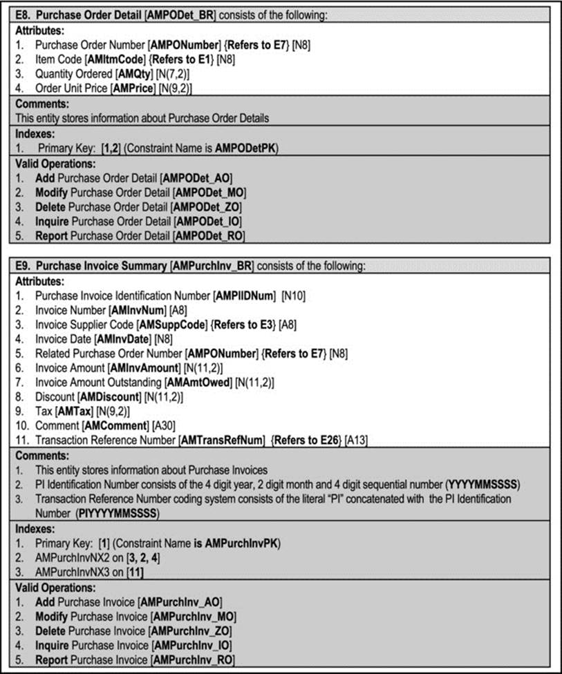
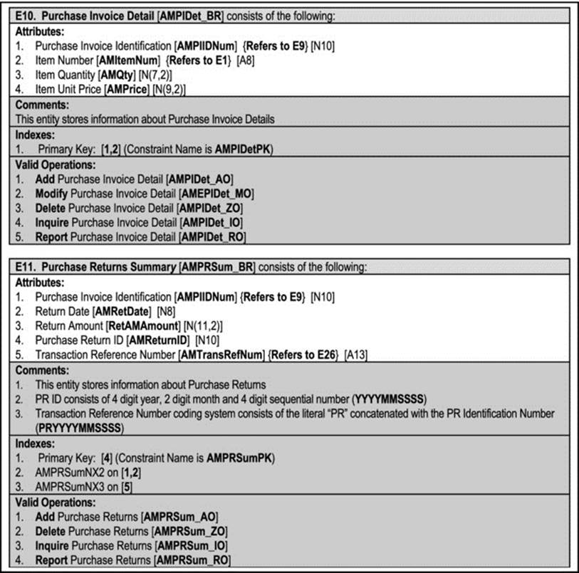
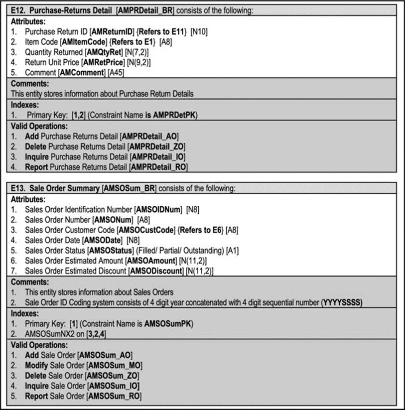
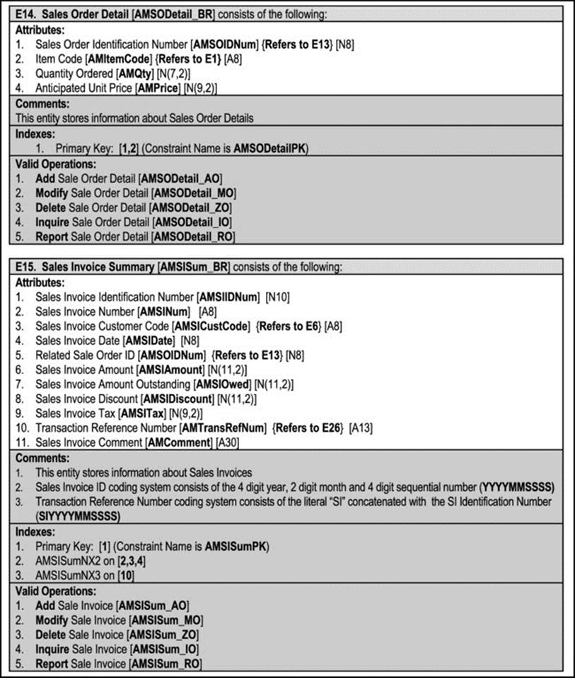
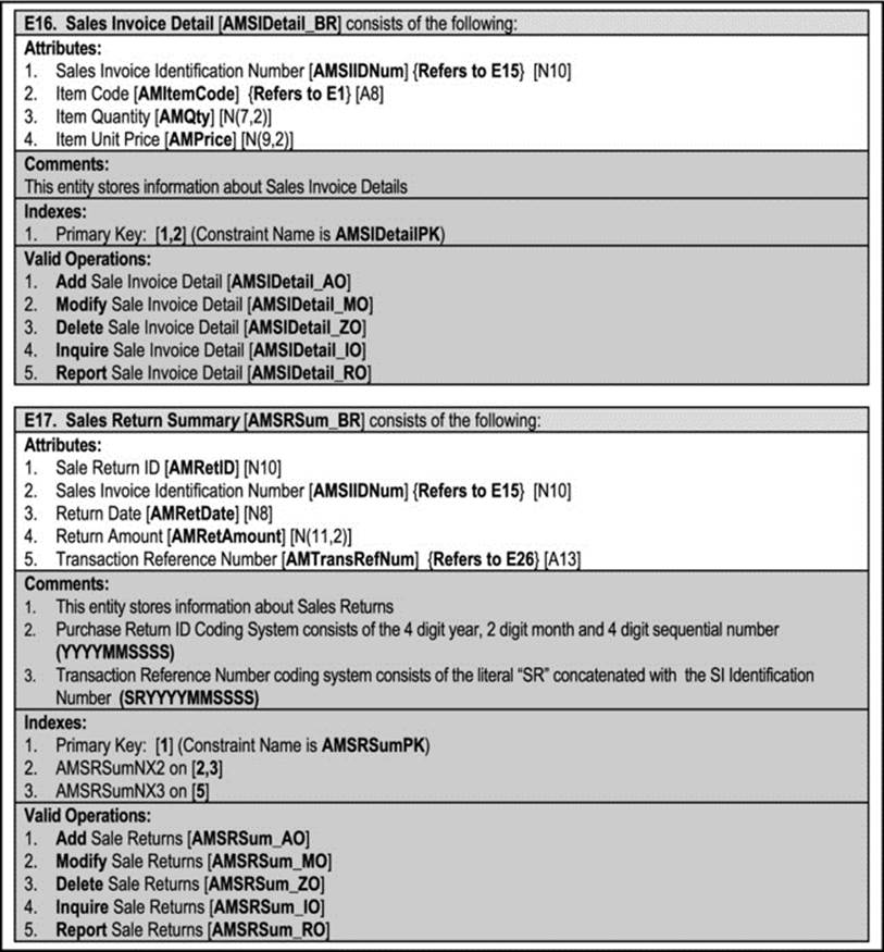
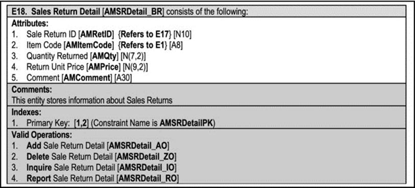
Figure A10-4. O/ESG for the Acquisitions Management Subsystem
A10.2.3 Financial Management Subsystem
Following is the O/ESG for each information entity comprising this subsystem (Figure A10-5):
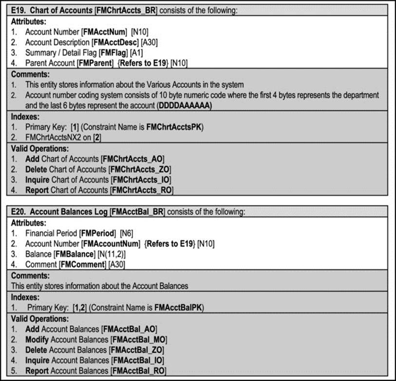
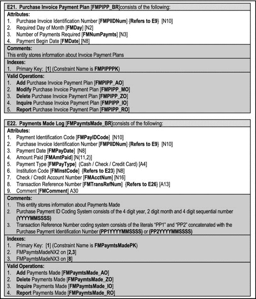
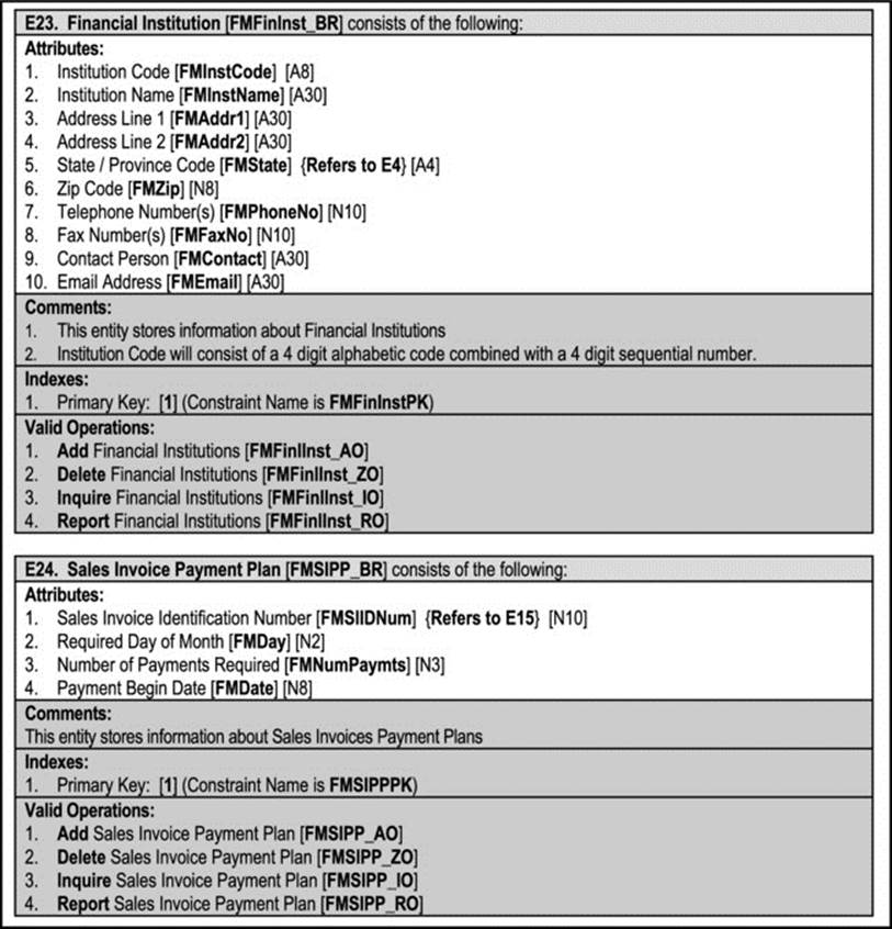
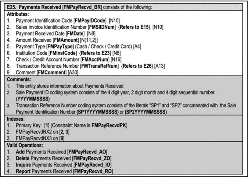
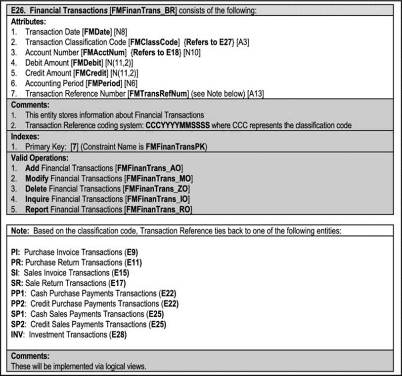
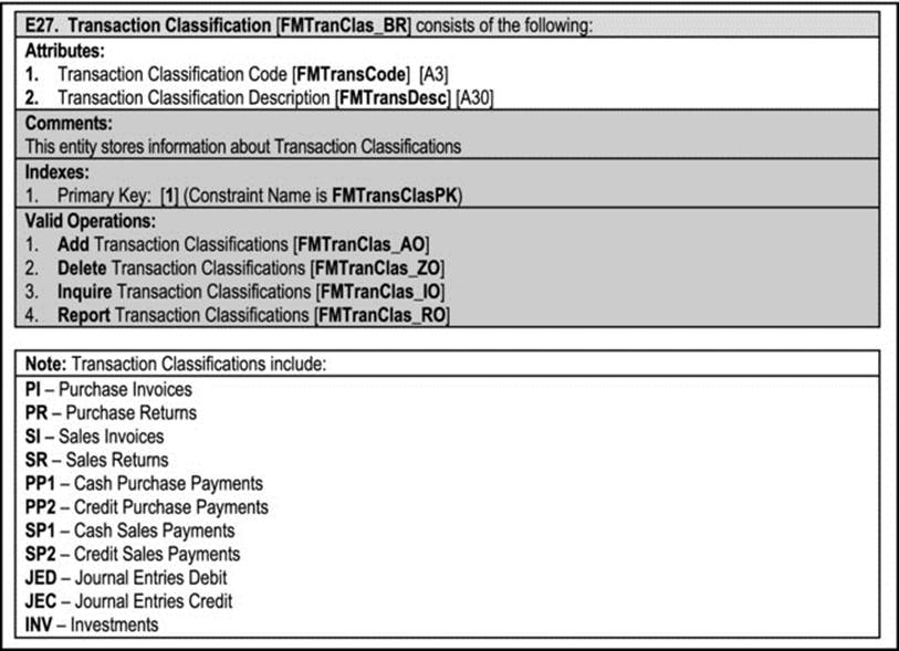
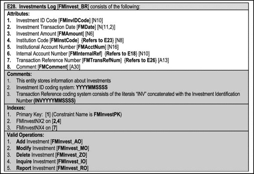
Figure A10-5. O/ESG for the Financial Management Subsystem
A10.2.4 Systems Control Subsystem
Following is the O/ESG for each information entity comprising this subsystem ( Figure A10-6):
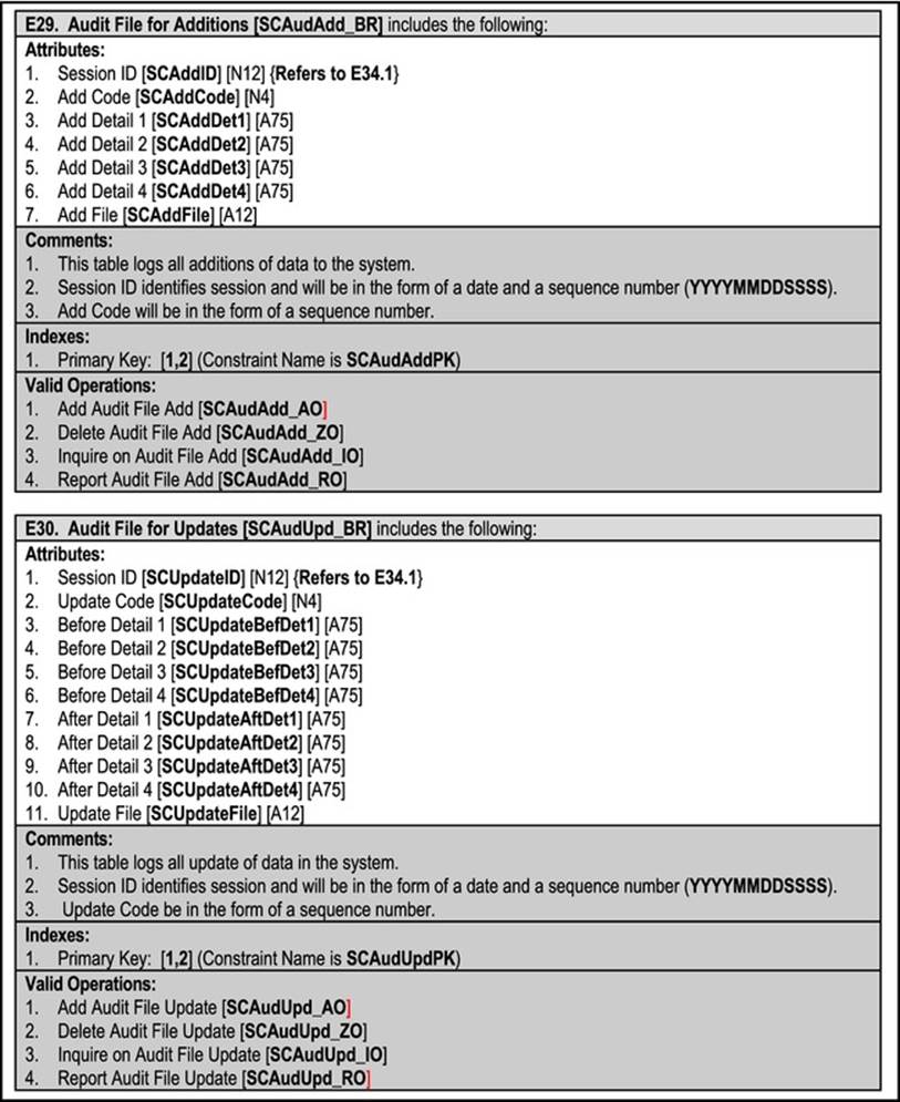
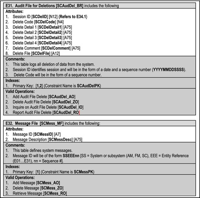
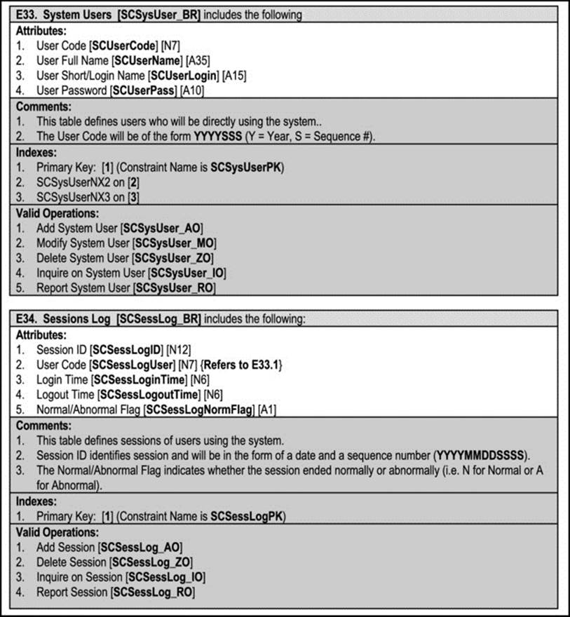
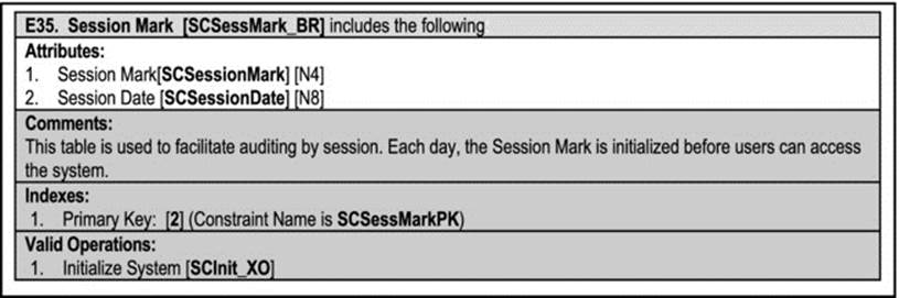
Figure A10-6. O/ESG for the System Controls Subsystem
A10.3 Operations Specification
In this section, operation specifications for selected operations in the system are provided. The algorithms needed for some of the operations (for different entities) are similar. Therefore, in the interest of brevity, instead of repeating the same pseudo code for these similar operations, the following generic operation outlines will be referenced. The section proceeds as follows:
· Generic Pseudo-codes
· Acquisitions Management Subsystem
· Financial Management Subsystem
· System Controls Subsystem
A10.3.1 Generic Pseudo-codes
Generic pseudo-codes are provided for the ADD operation, the MODIFY operation and the DELETE operation in Figure A10-7, A10-8 and A10-9 respectively.
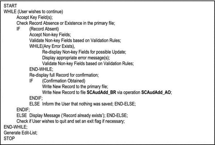
Figure A10-7. Generic ADD Pseudo-code
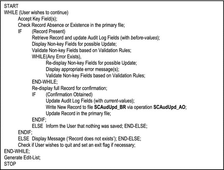
Figure A10-8. Generic MODIFY Pseudo-code
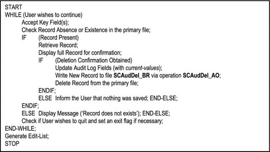
Figure A10-9. Generic DELETE Pseudo-code
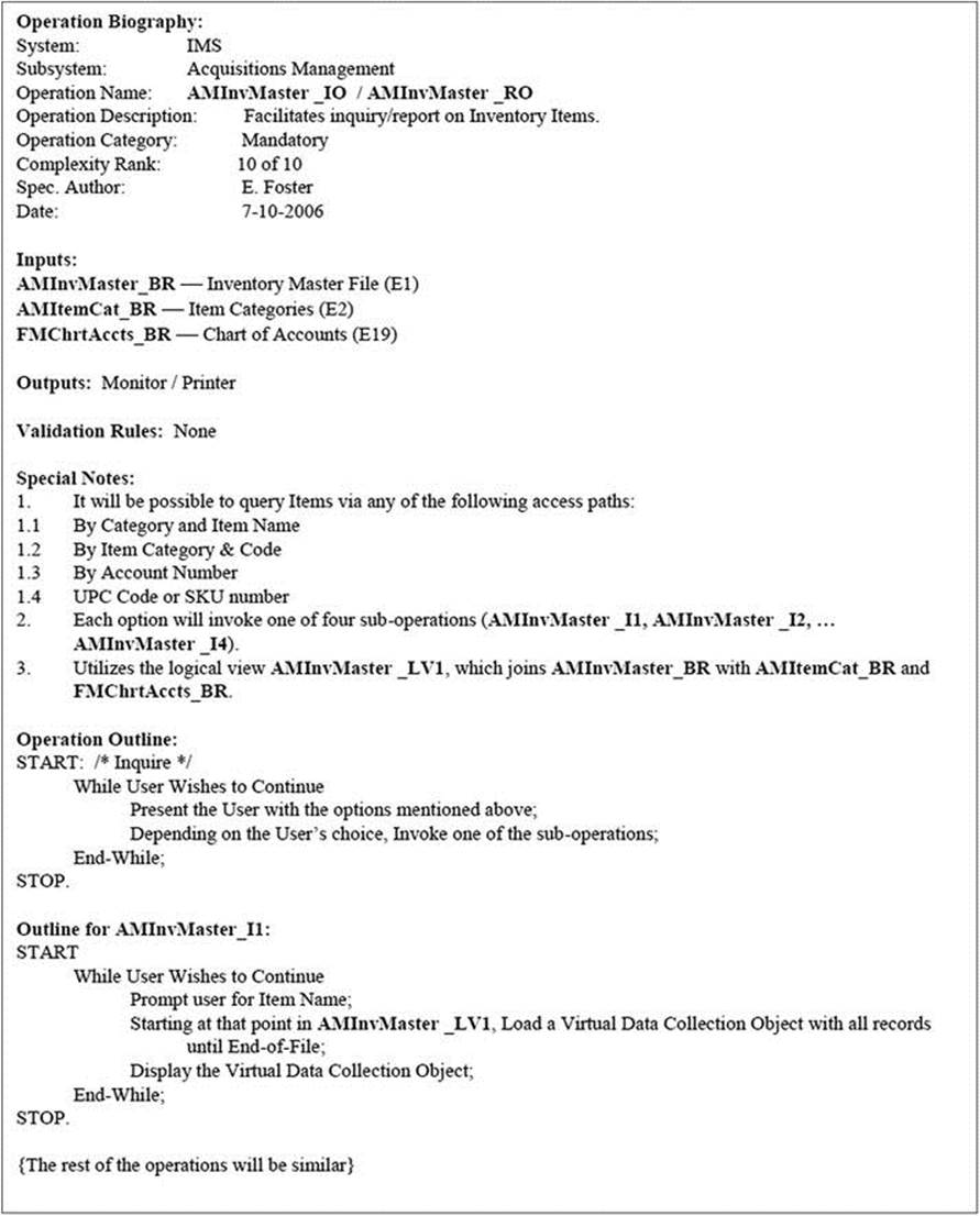
A10.3.2 Acquisitions Management Subsystem
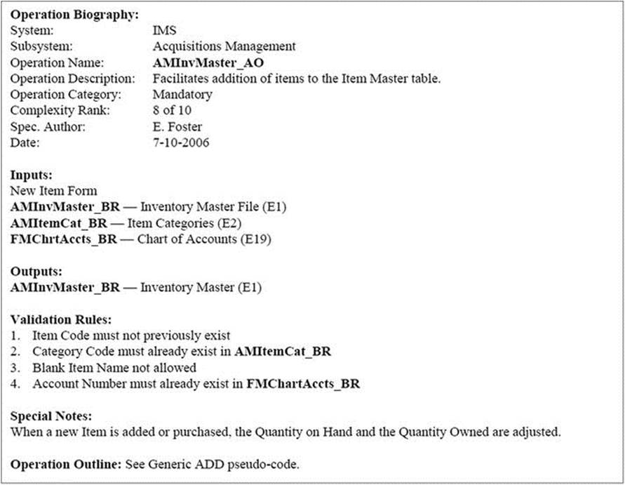
The operation specifications for operations in the Acquisitions Management Subsystem (AMS) follow:
E1_A: Add Inventory Items
E1_M: Modify Inventory Items
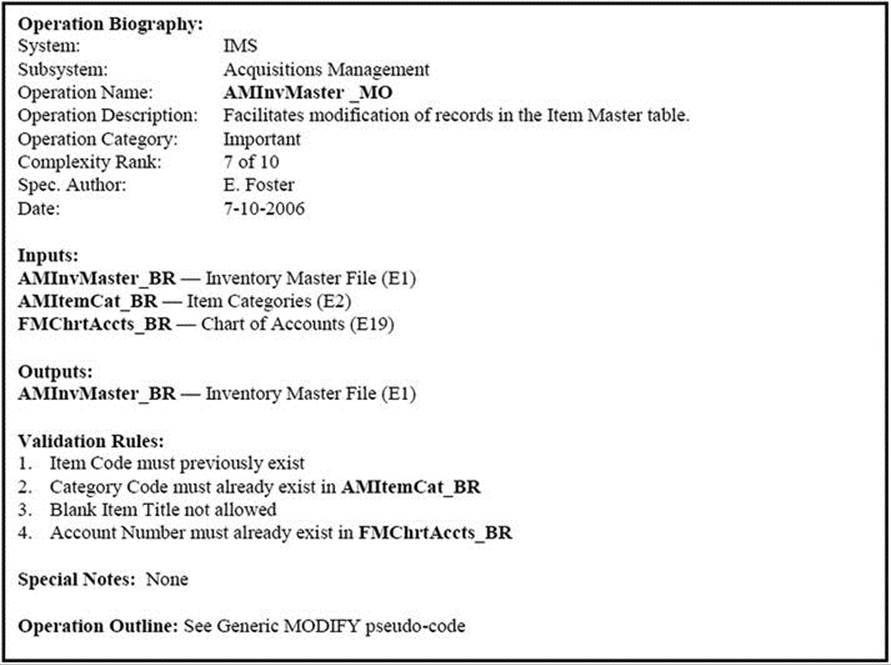
E1_Z: Delete Inventory Items
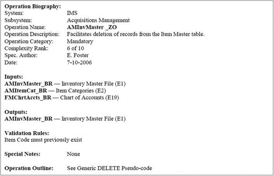
E1_I / E1_R: Inquiry/Report on Inventory Items
![]()
A10.3.3 Financial Management Subsystem
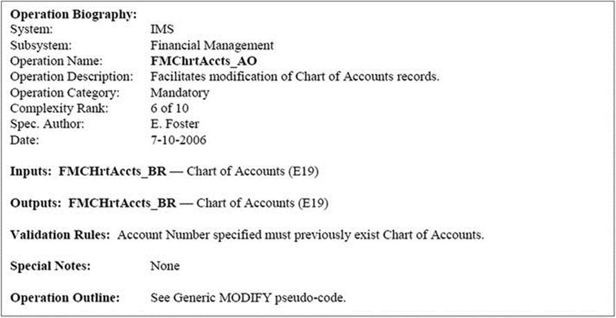
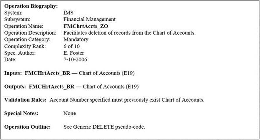
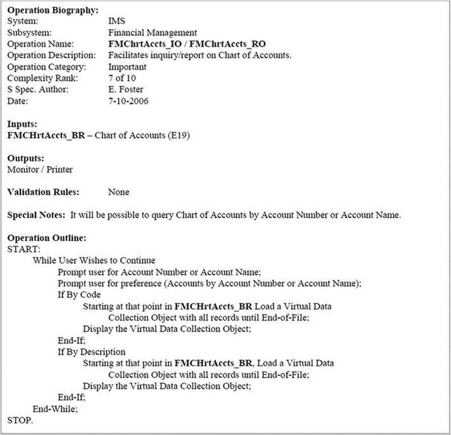
The operation specifications for operations in the Financial Management Subsystem (FMS) follow:
E19_A: Add Accounts to Chart of Accounts
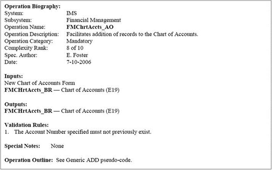
E19_M: Modify Accounts
E19_Z: Delete Accounts
E19_I / E19_R: Inquiry/Report on Chart of Accounts
![]()
A10.3.4 System Controls Subsystem
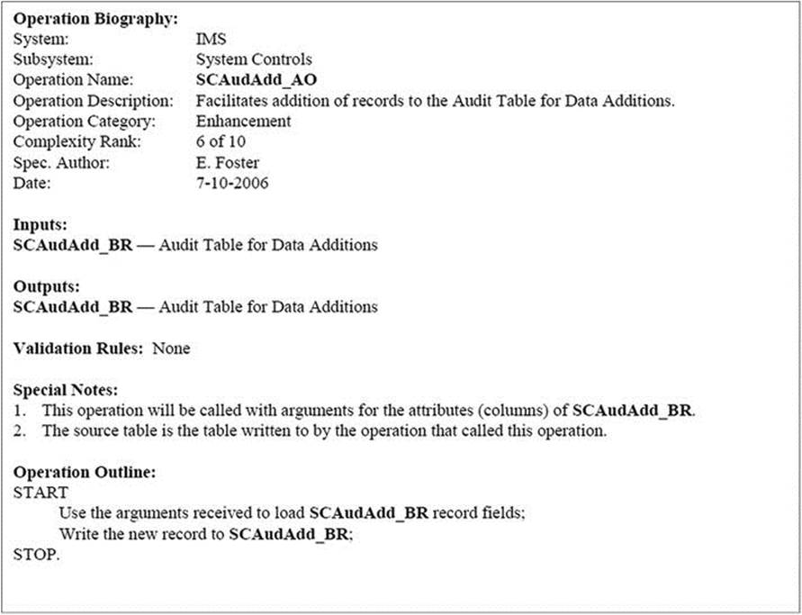
The operation specifications for operations in the System Controls Subsystem (SCS) follow:
E29_A: Add to the Audit Table for Data Additions
![]() Note This operation requires a different logic from the generic ADD operation.
Note This operation requires a different logic from the generic ADD operation.
E29_Z: Delete from the Audit Table for Data Additions
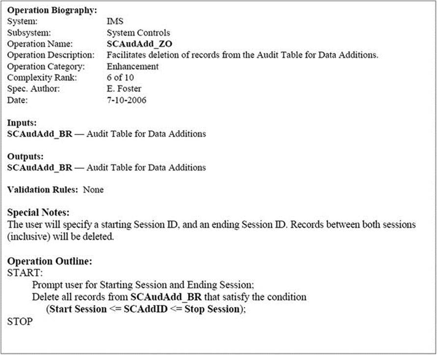
![]() Note This operation requires a different logic from the generic DELETE operation.
Note This operation requires a different logic from the generic DELETE operation.
E29_I / E29_R: Inquiry/Report on the Audit Table for Data Additions

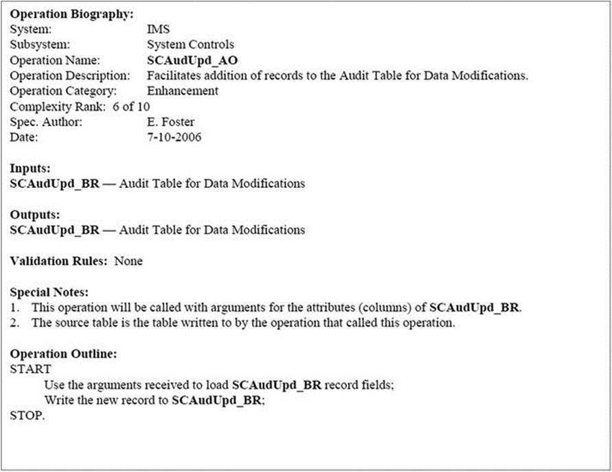
E30_A: Add to Audit Table for Data Modifications
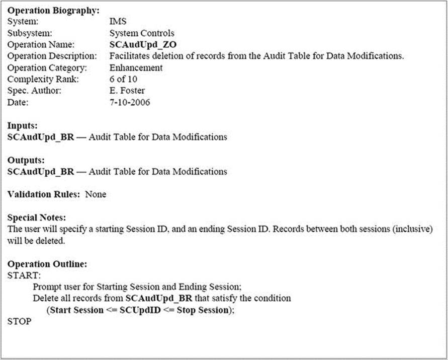
E30_Z: Delete from Audit Table for Data Modifications
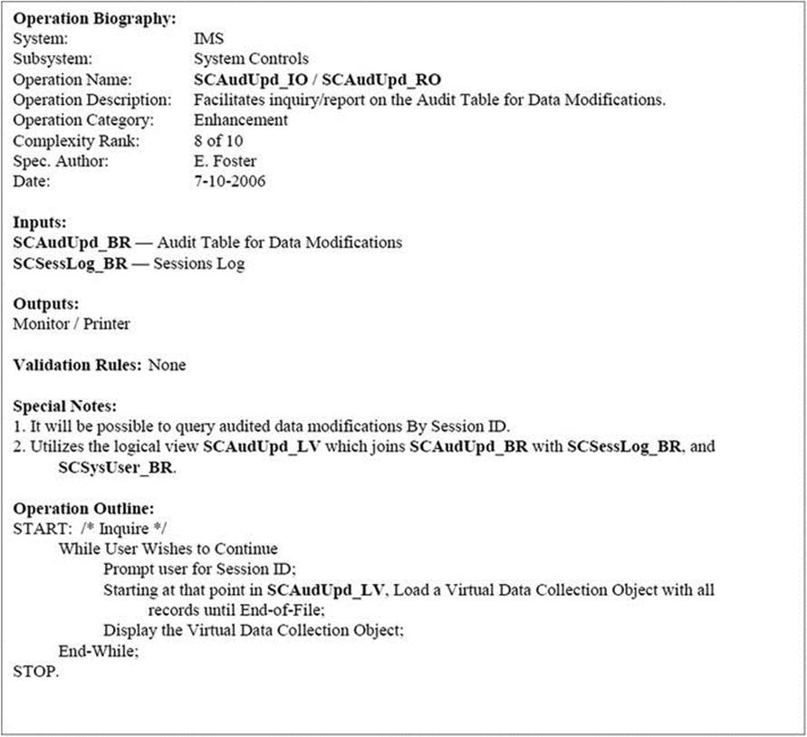
E30_I / E30_R: Inquiry/Report on Audit Table for Data Modifications
E31_A: Add to Audit Table for Data Deletions
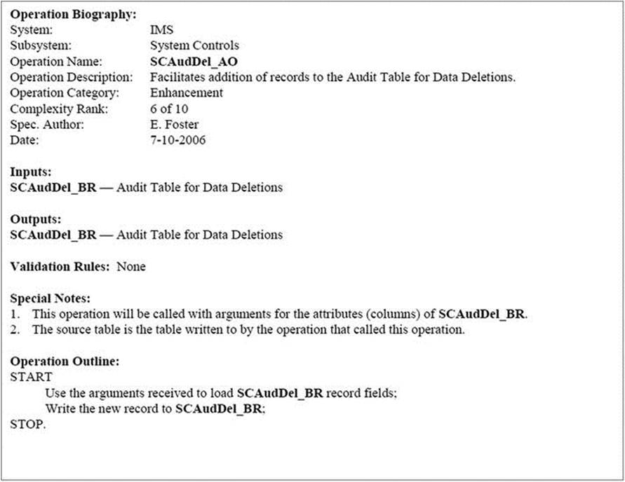
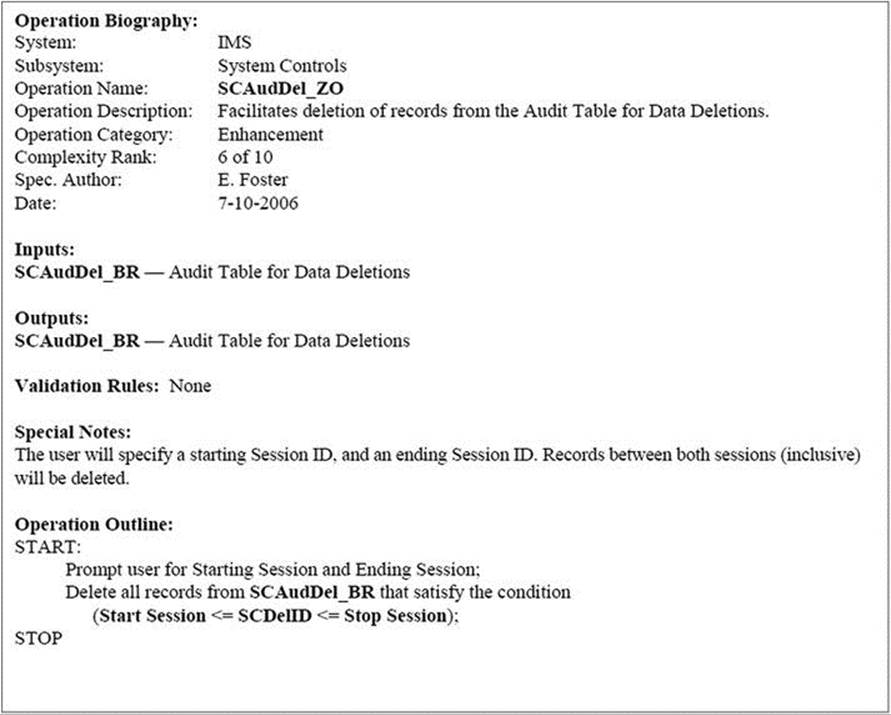
E31_Z: Delete from Audit Table for Data Deletions
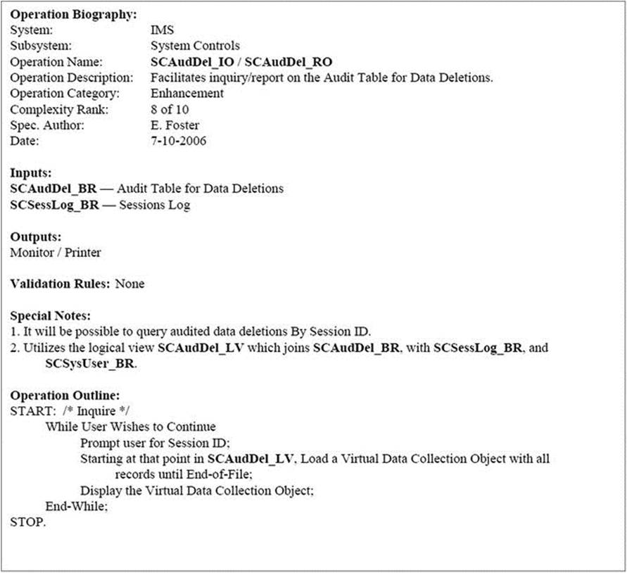
E31_I / E31_R: Inquiry/Report on Audit Table for Data Deletions
![]()
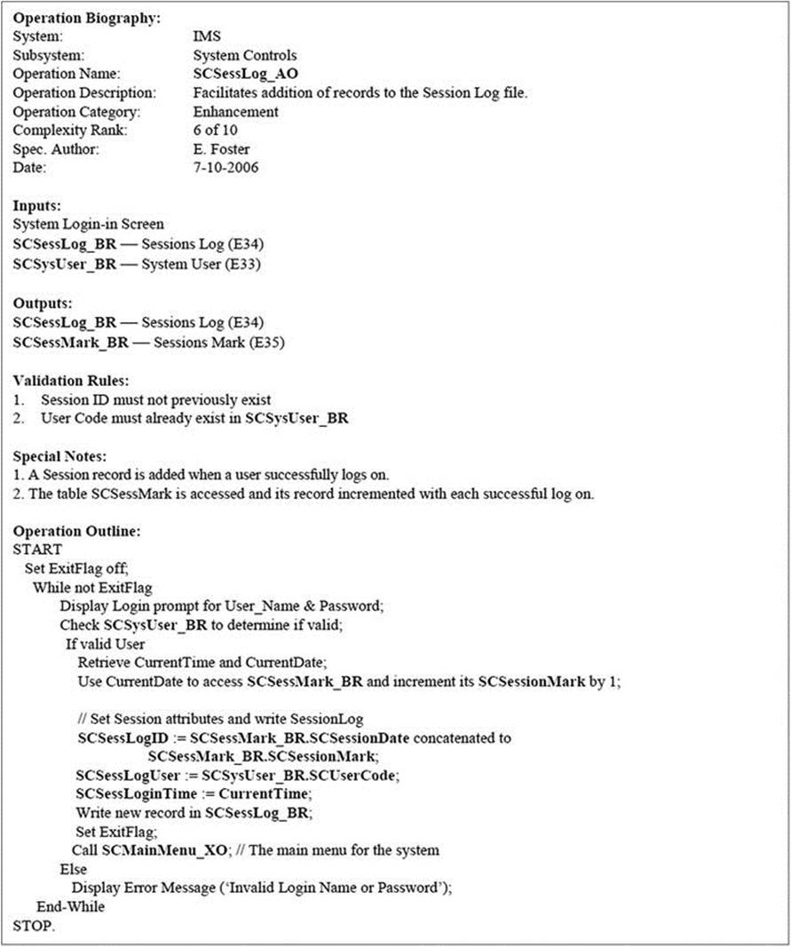
E34_A: Add Session Log Entry
E34_Z: Delete Sessions from Sessions Log
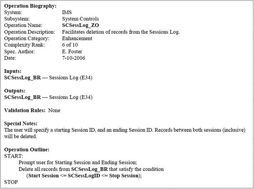
![]() Note Only authorized personnel must have access to this operation.
Note Only authorized personnel must have access to this operation.
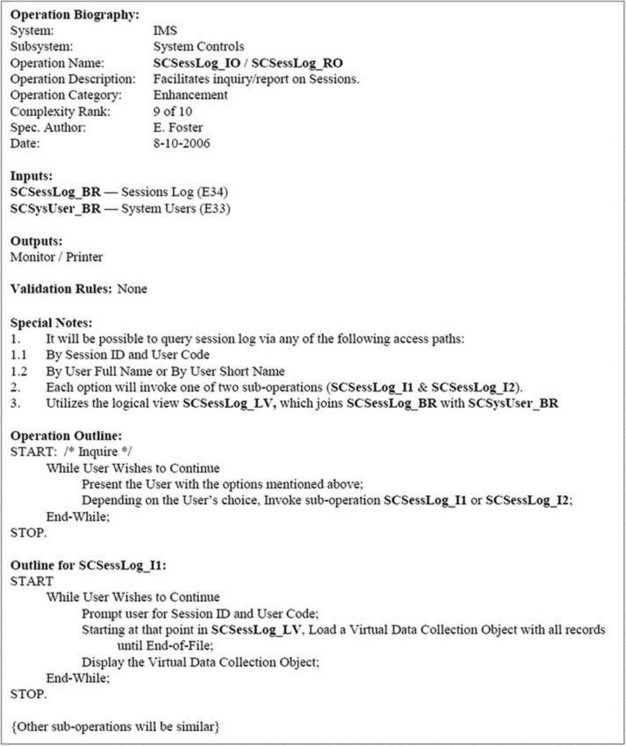
E34_I / E34_R: Inquiry/Report on Sessions
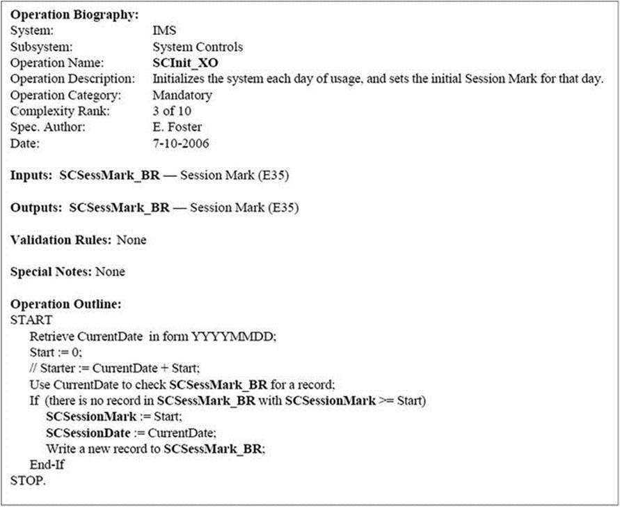
E35_X: System Initialization Operation:
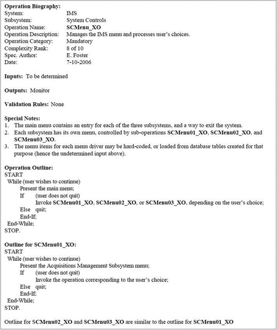
E0_X: System Main Menu Operation
A10.4 User Interface Specification
The user interface design is based on Schneiderman’s object-action interface (OAI) model for user interfaces. The real benefit of this approach is that it is consistent with the way people tend to think: People do not think about the functional intricacies of their daily activities; rather, they think about objects and what they desire to do with them. Because of the natural fit to the typical thought process on the job, user learning will be enhanced.
The menu system will be hierarchical, as represented in the user interface topology chart (UITC) of Figure A10-10. The user interface will be a GUI with the following features:
· At the Inventory management system (IMS):highest level, the main menu will consist of three options representing the three subsystems.
· For each subsystem, the menu options will point to each information entity managed in that subsystem.
· Any option taken from a subsystem menu will invoke a pop-up menu with the operations relevant to that particular information entity (object type).
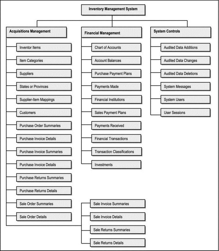
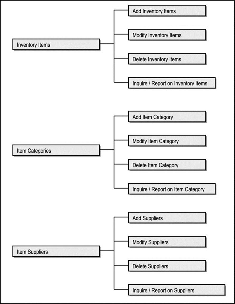
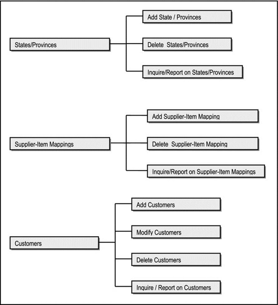
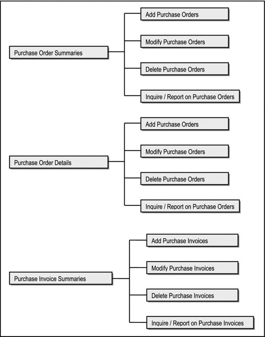
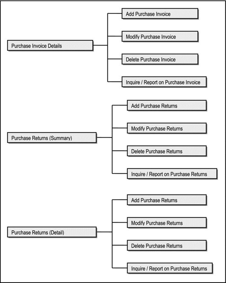
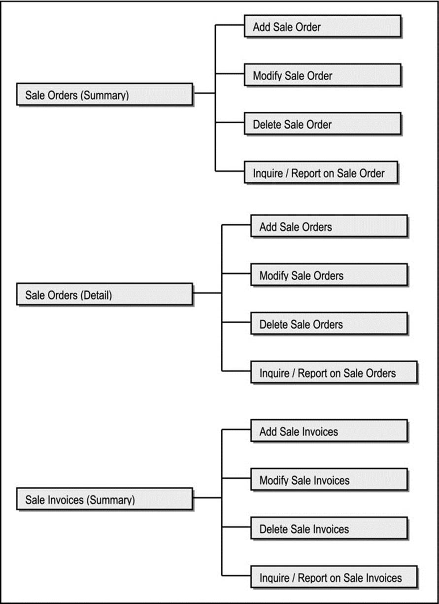
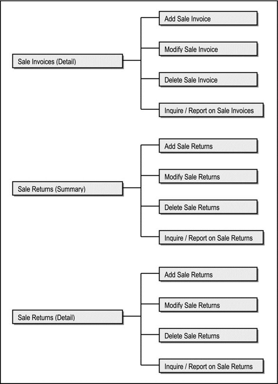
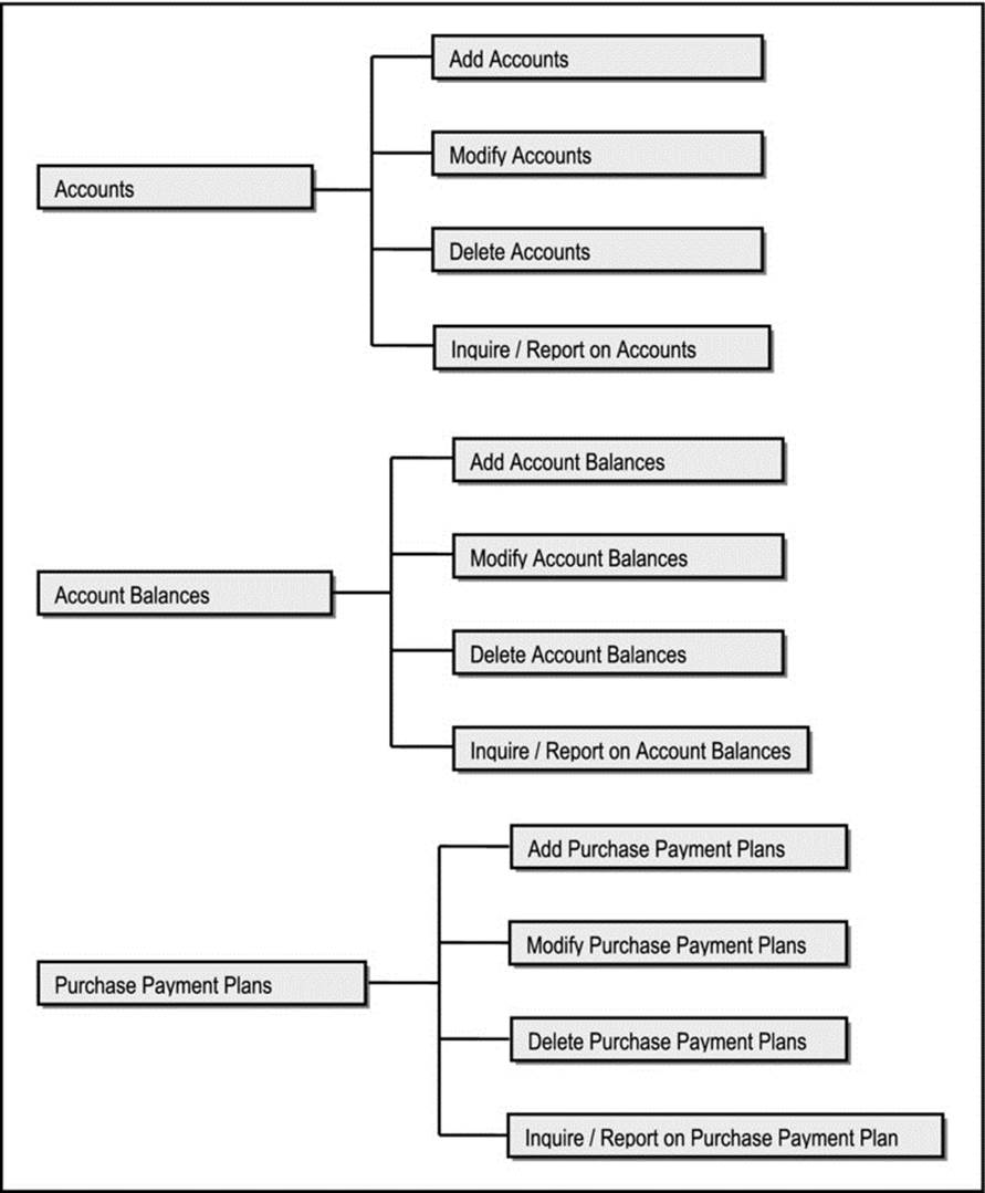
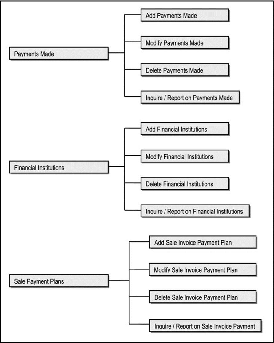
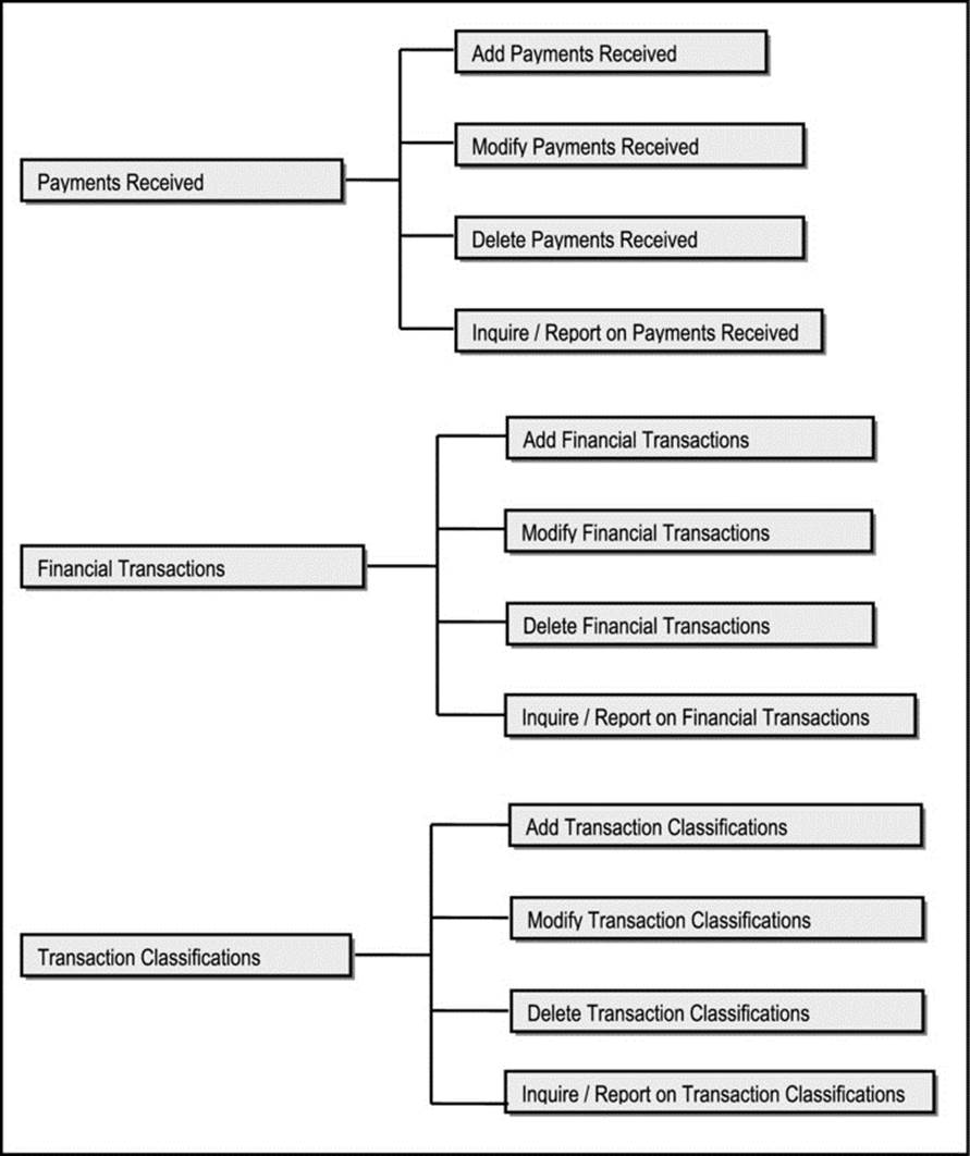
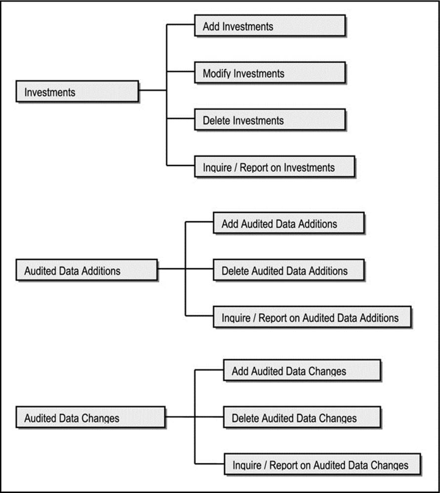
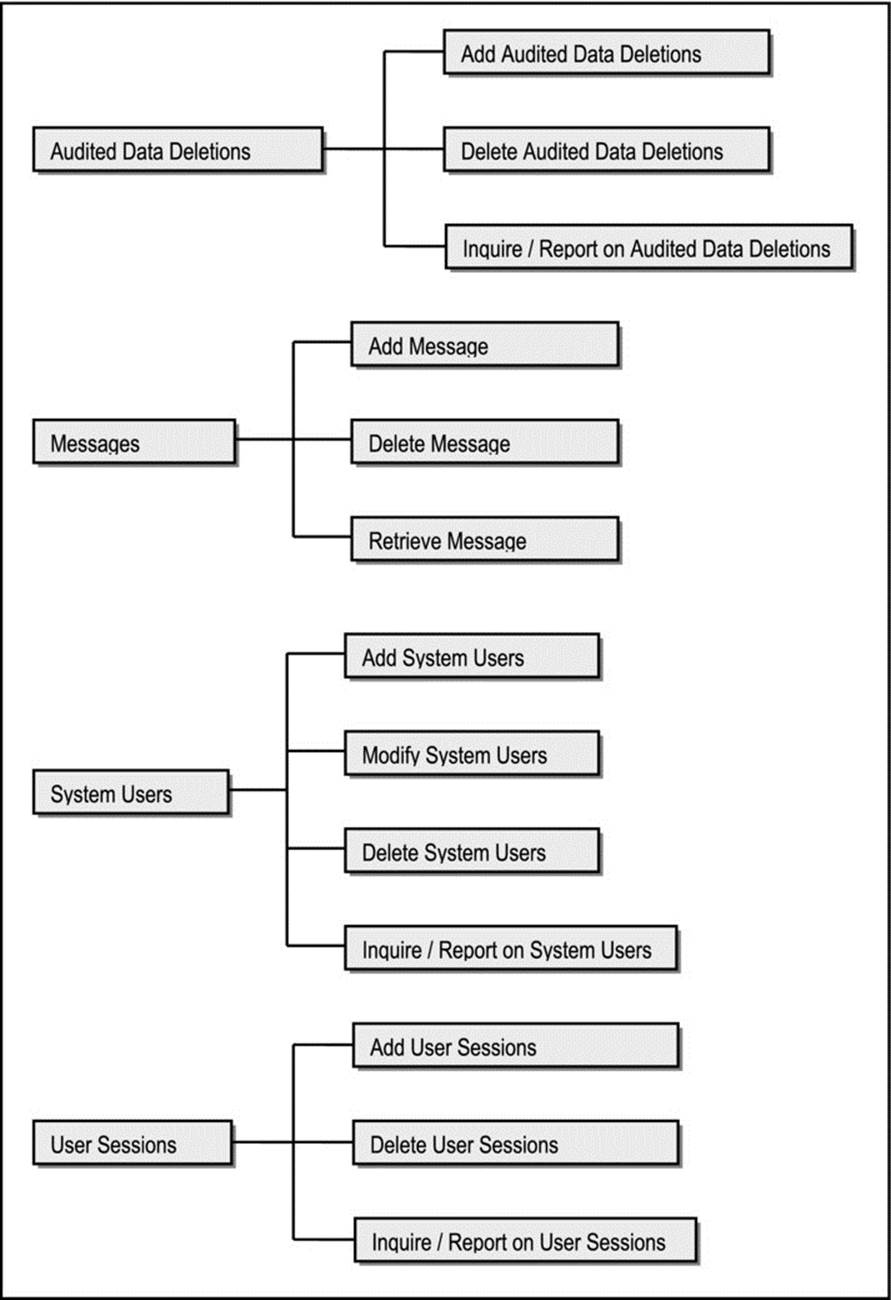
Figure A10-10. UITC for the IMS
This user interface can be easily implemented using an OO RAD tool such as Delphi or NetBeans. Moreover, it can be implemented in one of two ways:
· Static Approach: The options may be hard-coded into four menu operations — a main menu and one for each subsystem. For each option taken by the end-user, the appropriate operation would be invoked. This approach is simple but not very flexible. Whenever options are to be changed or new options added, the appropriate menu operation(s) have to be modified.
· Dynamic Approach: The options may be loaded into database tables created for that purpose. Each entry would be the option description along with the system name of the actual operation to be invoked. When the user selects an option, the corresponding operation for that option is invoked. The approach provides more flexibility to managers of the system: Menu changes (modifications or option additions) will not necessitate changes to the menu operations. Obviously, this approach requires a bit more intelligent programming effort.
![]() Note Even without OO RAD tools, the user interface prescribed here can still be employed to yield the same benefits.
Note Even without OO RAD tools, the user interface prescribed here can still be employed to yield the same benefits.
A10.5 Message and Help Specifications
This brief section addresses message design and help design.
A10.5.1 Message Specification
All user messages will be stored in a system-wide message file (as a database table) called SCMess_MF (see entity E32 of Figure A10-6). Unique codes will be given to each message so they can be accessed easier. Messages will be displayed in the form of pop-up messages.
A10.5.2 Help Specification
The system will host a hypermedia-based help system. Users will access the hypermedia help by clicking appropriate links until they get to the desired help they seek. Additionally, the help system will be organized according to the UITC, so that help will be provided operation-by-operation. As the system matures, the help system can be improved to include context-sensitivity.
A10.6 Summary and Concluding Remarks
This design specification has outlined the blueprint for an Inventory Management System that will be robust, and adaptable to any organization. It includes the following:
· An overview of the system, including problem definition, proposed solution, and system architecture. The overview includes an information topology chart (ITC) that identifies the key information entities in three sub-systems of the system — Acquisitions Management, Financial Management, and System Controls.
· Database specification that includes a set of design conventions, naming conventions, and an O/ESG for each of the information entities comprising the system in all three sub-systems.
· Operations specification that includes an EOS for each operation comprising the system in all three sub-systems.
· User interface specification that outlines menu hierarchy via a user interface topology chart (UITC).
· Message specification that outlines how system messages will be handled, and a help specification that outlines how the help system will be implemented.
Possible future enhancements include the following:
· Point-of-Sale Subsystem: This would basically provide a front-end that allows point-of-sale machines to be used. These machines would have to be programmed to interface with the system in a seamless manner.
· Just-in-Time Subsystem: This would require automating the re-order process. The idea is to trigger an automatic purchase order to a supplier for goods, once the re-order limit for that item has been reached.
· Refine the System Controls Subsystem: More features can be added to the System Controls Subsystem. For instance, a feature could be added that dynamically generates different menus for different users, depending on the features they have been authorized to access.
Despite these potential enhancements, this is a solid start. Now have fun with the development and implementation!