The Maker's Manual: A Practical Guide to the New Industrial Revolution 1st Edition (2015)
Part IV. Giving Life to Objects
Chapter 16. Arduino
Once upon a time, you could be considered an electrical wizard simply by creating a push-button electric doorbell for your house. As the field of electronics grew more complicated, hobby electronics also grew complicated. Soon hobbyists were making their own tube radios, then transistor radios, then their own televisions. In 1975, the field reached a peak of complexity, when hobbyists could even build their own desktop computer, the Altair. But that high point also marked the beginning of a serious dropoff in home hobby electronics. You didn’t need to know much electrical theory to wire up a doorbell, but building a computer required specialized knowledge in mathematics and physics. This was a high barrier that beginners had to overcome, and the learning curve was substantial, especially for people without specific technical competencies. Then, in the mid-2000s, things started to turn around...
What is Arduino?
Arduino (Figure 16-1) is a sort of small computer--simple, powerful, and versatile--which can interact with the surrounding physical world. At $25-$30 for the Arduino Uno, it’s very affordable. You can connect it to sensors (devices that give you information) and actuators (devices able to perform actions), and program it to follow rules and instructions that you set. For example, you can use Arduino to control a greenhouse: when the humidity level changes, Arduino can start or stop the ventilators to keep optimum conditions for your plants.
Arduino grew out of work done at the Interaction Design Institute Ivrea in Ivrea, Italy. Students there were building small interactive devices using a microcontroller called a Basic Stamp, which cost about $100. Eager to make interactive computing more affordable, educators and engineers Massimo Banzi, David Cuartielles, Gianluca Martino, and David Mellis created the open source Arduino microcontroller, which retails for about $30. Shortly after the creation of Arduino, Tom Igoe, a professor at the Interactive Telecommunications Program at New York University, joined the team.
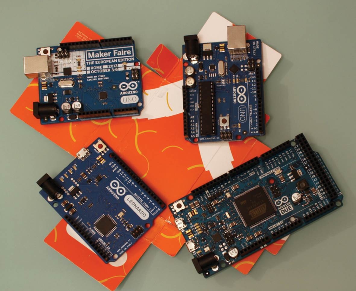
Figure 16-1. Some versions of Arduino, including the special edition for the Maker Faire.
To program Arduino’s behavior you need to write software using the Arduino Integrated Development Environment, or IDE. You can download this for free from the official website.
Beside interfacing with other physical components, Arduino can communicate with computer-run software, such as Processing and Python; you’ll see some examples of this kind of interaction in Chapter 18 and Chapter 19.
The Arduino board and its programming environment constitute a prototyping platform: you can plan and design around the Arduino, then decide to keep Arduino as the core of our project, or go with a custom designed solution. After all, an Arduino can do wonderful things, but if you find that you’re only use it to switch a light on, there are cheaper solutions.
One of best things about Arduino is that it is open source: all plans and instructions to make it are publicly available, so anyone could assemble their own board, or even improve it and adapt it to their needs. Another great advantage is that you can use the Arduino development environment with the Big Three operating systems: Windows, Macintosh, and Linux, making Arduino available to as many people as possible.
The software Structure
Arduino’s microcontroller--the “brains” of the board--is rather small as modern day computers go. It cannot handle large programs like word processors or web browsers. The programs you write--called “sketches” in Arduino parlance--will at most be a few screens long. The language in which you will write these sketches is a simplified version of the more complex C/C++, very similar to Processing, which itself is a simplified version of Java.
Sketches are divided in two separate sections: setup and loop. Setup runs once and handles the preparation for the program. For example, it might tell Arduino that the wire attached to pin number 9 is connected to a sensor, that the Arduino should output data to the serial port at a certain rate, or any other thing the Arduino needs to know before it gets to work. Loop comprises all the actions Arduino will carry out over and over and over, as long as it is supplied with power (for example, “Check the value detected by a sensor. If it is over a certain threshold, switch a light on. If it is under a certain threshold, turn the light off. Wait 10 seconds and start again”).
The sketch is stored in what is called “non-volatile” memory in the Arduino, which means that Arduino will remember it even after the power is turned off. When you restore power the next day, the next month, even the next year, Arduino will start carrying out its sketch: first the setup, once only, then the loop, indefinitely.
The Simplest Sketch
The simplest sketch (Example 16-1) doesn’t do anything at all. You can’t get any easier than this.
Example 16-1. An empty sketch
// lines starting with // are comments
void setup()
{
// here goes the initialization code
// it is carried out only once
}
void loop()
{
// here goes the main code
// it is carried out indefinitely
}
Not very interesting, is it? You can observe two things: first, whatever follows the characters // (double slash) is a comment and will be ignored; second, all setup and loop sections are marked by curly brackets: you’ll see that this is a way to group blocks of instructions.
Luckily, the development environment has many pre-made examples that show the various behaviors we can set up. Have a look at the Blink example (click File→Examples→01.Basics→Blink to load it, as shown in Figure 16-2.
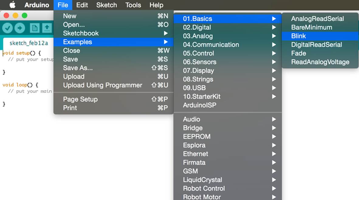
Figure 16-2. Where to find the “Blink” sketch
This sketch makes an LED on your board blink (see Figure 16-3); we’ll show a slightly modified version with its comments:
Example 16-2. Blinking an LED
void setup()
{
// actuator on pin 13 (specifically, an LED) we want to operate
pinMode(13, OUTPUT);
}
void loop()
{
// switch on the LED
digitalWrite(13, HIGH);
// wait one second--one thousand milliseconds
delay(1000);
// switch off the LED
digitalWrite(13, LOW);
// wait one second
delay(1000);
}
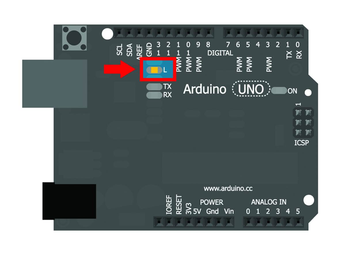
Figure 16-3. The LED mounted on the board is connected to pin 13.
Let’s look at the code. Probably the first thing you notice is that every instruction that is not a comment ends in a semicolon (;). This is because Arduino expects every instruction to know where it ends and the next one begins. The way Arduino does that is to separate the statements with a semicolon. Without the semicolon, the Arduino will refuse to try to make sense of the rest of the program.
As if this wasn’t enough, the Arduino is so meticulous that it recognizes the difference between upper and lower case. The command DigitalWrite is distinctly different from digitalWrite (the correct form), or even digitalwrite.
How to Upload a Sketch in Arduino
So, you’ve got the Blink sketch in your IDE. How do you get it into the Arduino hardware? Before uploading a program in Arduino, it needs to be verified: the development environment has to translate (compile) what we have written into a long series of 0s and 1s (difficult for humans to understand, yet perfectly clear for the hardware) and tell us whether it encountered an error doing so.
Before you verify the sketch, connect your Arduino to your computer using the appropriate USB cable (for example, with the UNO, it’s a USB A to B cable; with the Leonardo, a USB Micro cable). Next, click the Tools menu, and click Port, then select the port with the name of your Arduino board next to it (if there’s more than one listing for your Arduino, choose either one). Figure 16-4 shows this. The list may be quite long. After you’ve done that, click Tools→Board and choose your board type (such as Arduino Uno) from the menu. This configures the Arduino IDE to be able to connect to the Arduino (not needed until the next step) and also to use the verification settings appropriate for your model of Arduino.
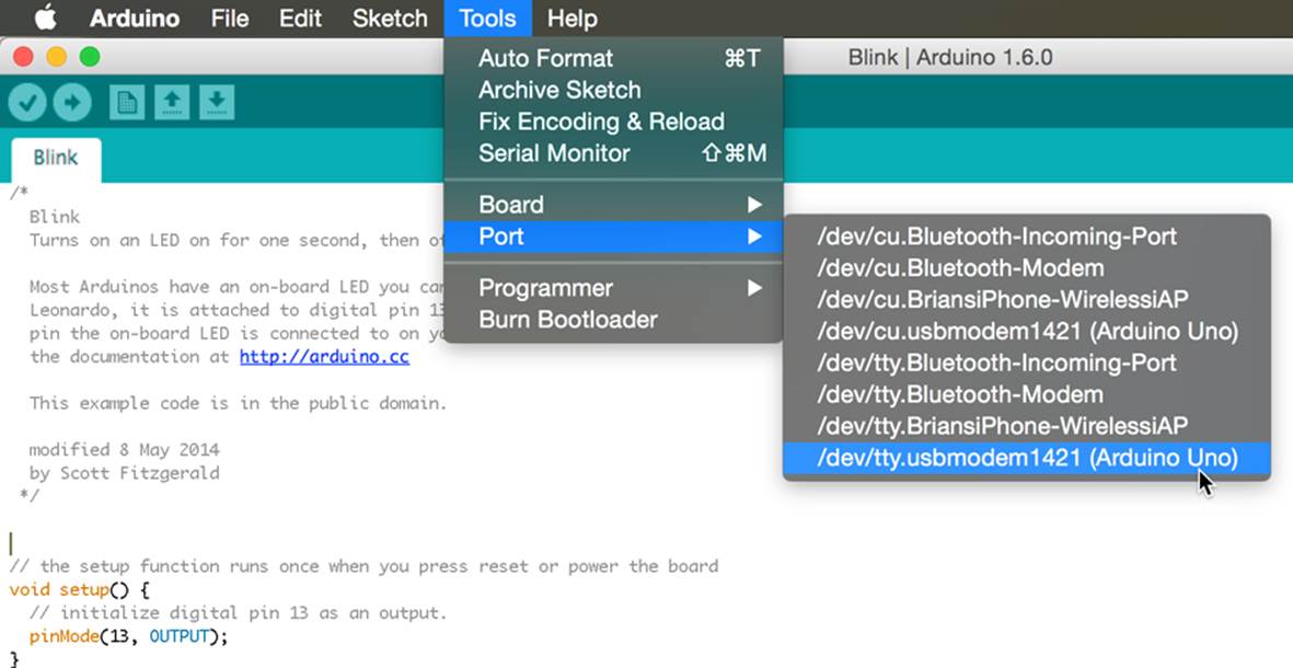
Figure 16-4. Choosing the right port
Now you’re ready to verify the sketch: click the Verify button as shown in Figure 16-5.
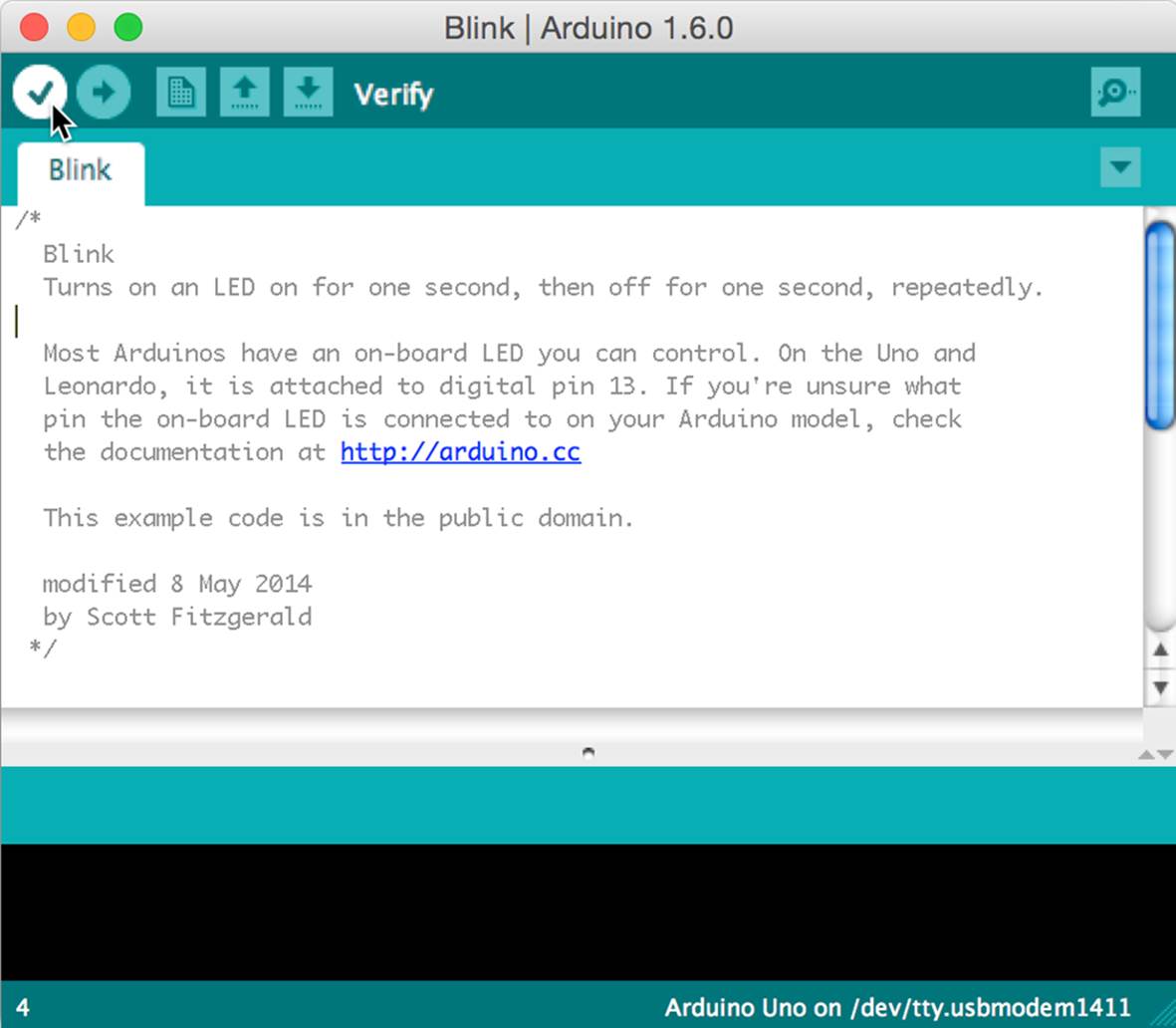
Figure 16-5. Verifying a sketch
Once you’ve verified your sketch, you can upload it to your Arduino. Click the Upload button, and your compiled sketch gets sent to the actual hardware, as shown in Figure 16-6.
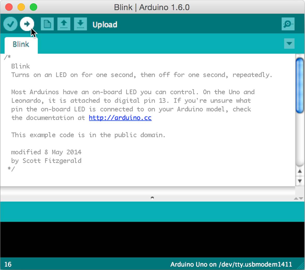
Figure 16-6. Uploading a sketch.
If everything goes well, you’ll see the LEDs shown in Figure 16-7 flash, indicating that the computer is transferring your compiled instructions to Arduino. After a few seconds you’ll see the LED on Arduino blink steadily.
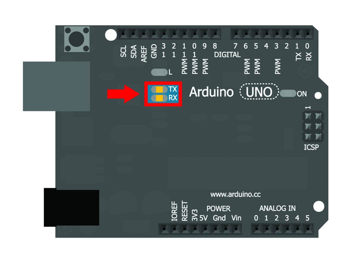
Figure 16-7. The TX and RX LEDs show your upload in action
In the next section, we’ll go into some more detail:
§ how to tell Arduino where you want to connect sensors and actuators, then
§ how to read the sensor values and tell the actuators what to do
Interacting with the Physical World
Let’s introduce the first simple commands that we can use to give our creations life.
Defining a Pin’s Behavior
On an Arduino board there are several pins; in Figure 16-8 you’ll see some of them highlighted, numbered from 0 to 13. These pins are all digital, only able to process 0 and 1, all or nothing. If they were water taps they could only be either fully open or fully closed.
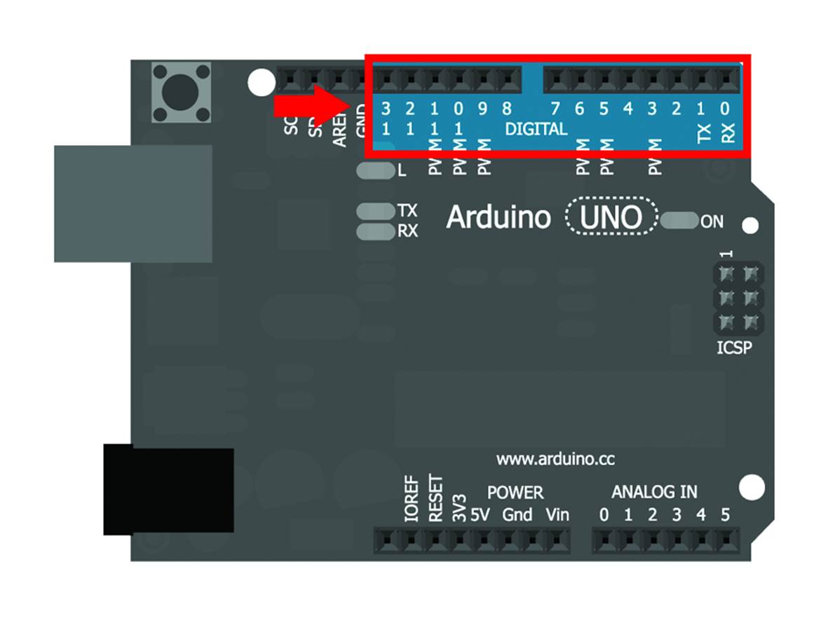
Figure 16-8. Digital pins of Arduino.
One of the advantages of a prototyping platform like Arduino is the ability to change the digital pins’ behavior and decide whether we want to use them as inputs or outputs. The instructions you need to put into the setup block for either is very easy. For example, to set pin number 13 as an output, all you need to do is to add the following code:
pinMode(13, OUTPUT);
Whereas if we want pin number 7 to act as an input, the instruction is:
pinMode(7, INPUT);
Basically, the pinMode command accepts two parameters: the first one determines which pin it will operate on, the second one tells whether the pin must be an input (INPUT) or an output (OUTPUT). If you declare a pin to be an input and then try to output data to it, or the other way round, the Arduino or the attached electronic might get damaged.
Shall We Switch It On?
If you have identified a pin as an output, you can “switch it on” or “switch it off” using the command digitalWrite. This function accepts two parameters: the first one is the pin that we want to operate on, the second one represents what you want it to do, i.e. whether any current will be let out from the pin or not. With digital pins, you can only switch it on or off, the tap is fully open or fully closed, no mid-way.
To “switch on” pin 13, you’d write:
digitalWrite(13, HIGH);
To “switch it off”, you’d write:
digitalWrite(13, LOW);
You see both these instructions in the Blink sketch. The LED on the board, connected to pin 13, switches on and off when the value of the second parameter is HIGH or LOW, respectively.
Not So Fast...
Sometimes you might want to slow the action down. You can add a pause into the execution of the instructions that Arduino follows. To do this, you can use the function delay, which needs a parameter indicating the number of milliseconds that the Arduino has to wait before carrying out the next instruction. For example, to tell Arduino to stop for one second, you need to write:
delay(1000);
You need to write 1000 instead of 1 because one thousand milliseconds equals one second. As usual, don’t forget the semicolon at the end. For a two and a half seconds pause, you’d write:
delay(2500);
Edit the Blink sketch to change the length of the delay, then verify and upload it; you’ll see the difference straight away when the LED blinks at a different rate than before.
Pardon Me, You Were Saying?
You now know how to have Arduino carry out an action, even if it is just switching on an LED. Now let’s teach this LED to switch on only in a certain condition: when you press a button. How can you do that? Let’s start by assembling the circuit. You’ll need the following to do this (everything listed here, with the exception of the Arduino Uno, is included in Maker Shed’s Mintronics Survival Pack):
§ One LED
§ One 220 ohm resistor
§ One 10 kilohm (aka 10K) resistor
§ A pushbutton
§ Assorted jumper wires
§ A mini breadboard
Start with the LED. Rather than using the onboard one (Figure 16-3), which is small, we’re using an external one. Look at Figure 16-9 to see how to set it up. Note that you’re connecting it across the gap in the breadboard, so you need wires both from GND and pin 13 to the breadboard, and another wire to bridge the gap to the LED’s negative lead. For the positive lead of the LED, you’re bridging the gap with a 220 ohm resistor to protect the LED and the Arduino from overcurrent. See “Resistors” for a refresher on working with resistors.
For the button, you also need to add a resistor, to protect the Arduino’s input pin and to make the input circuit more reliable. A 10 kilohm (10K) resistor will do. Take the resistor and use it to connect the column that the GND wire is in to the column that the button is in. Then, connect a wire from pin 7 to where the resistor meets the button as shown in Figure 16-9. Finally, connect the 5V pin to the button’s other lead as shown.
To set pin number 7 to input mode, you already know you have to write:
pinMode(7, INPUT);
But how do you know if the button is pressed or not? The function to find out if voltage on the pin is HIGH (pressed) or LOW (not pressed) is digitalRead. As with other functions, you have to specify which pin you want to read, in this case number 7:
digitalRead(7);
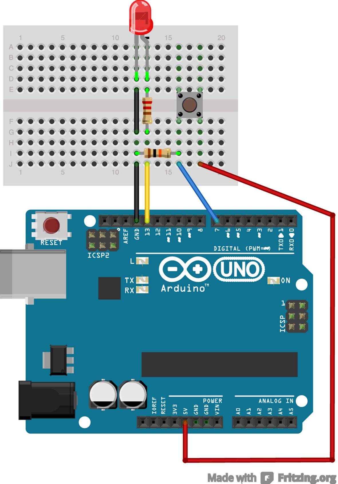
Figure 16-9. Using a button to switch an LED on
The digitalRead command is a little different from the functions you’ve seen so far, in that it returns a value: HIGH if there’s a voltage on the pin and LOW if not.
Where Do You Store Your Data?
What shall we do with the value that the digitalRead command returns? You can use it to set the value of a variable, which is kind of like a drawer with a name tag on it where you can put a value that you can check or edit every time you want. Let’s create a variable named read and give it the value returned by digitalRead. To do that, use the symbol = (the assignment operator):
int read = digitalRead(7);
What is that int in front of the name of the variable? It is a special term used to define what kind of data you’ll put in your “drawer”. In this case, you’re stating that the variable read will have an integer value (between -32,768 and 32,767). But... didn’t we say that digitalRead can only return HIGH or LOW? Right! These two values are constants, which you use to remember the meaning of the associated values. In the Arduino language there are many pre-defined constants: the values INPUT and OUTPUT, which you used to define the pin behavior, are constants. Arduino’s built-in constants are special constants called preprocessor macros, and we suggest you don’t use them (for consistency with Arduino programming style). If needed, you could write your own constants using a different method. You just need to put the term const in front of the statement you have already seen for variables:
const int RINGS_FOR_THE_ELVEN_KINGS = 3;
Conventionally, only upper case is used for constant names. This is in contrast to variables, which can change their value any time you want. Once you have defined a constant it remains, indeed, constant and unchanging.
You can choose the name of your variables and constants almost as you wish, as long as you stay with the characters A-Z, 0-9, and “_” (underscore), and avoid conflicts with other, already defined names. In order to improve the understanding of sketches you should choose meaningful names; while strange names such as AUF2RTX are valid, they’re not very meaningful, so you’d better avoid them.
What shall we write in our sketch? In the setup, you need to state that pin 7 is an input and 13 an output. You already know that you can write:
void setup()
{
pinMode(13, OUTPUT);
pinMode(7, INPUT);
}
However, in this way you would have to remember throughout the whole sketch that the LED is on pin 13 and the button is on pin 7. Thanks to the variables, you could write this instead:
int led = 13;
int button = 7;
void setup()
{
pinMode(led, OUTPUT);
pinMode(button, INPUT);
}
With this change you will be able to work out whether the button is pressed with a simple digitalRead(button); and switch on the LED by writing digitalWrite(led, HIGH);. Note that the variables have been defined outside the setup block: this is because if you declared the variables within the setup block, you could only use them in that block. This applies for all blocks; this idea is called visibility of variables or scope.
Normally, a computer executes all the instructions of the program, from start to finish, only once for the setup and continuously for the loop. Sometimes you want to modify this flow; for instance, you may want to see one action repeated several times or execute some of the instructions only upon certain conditions.
Only When I Say Go...
As we were saying, you want the light to switch on only if you are pressing the button. For this, you need to use a control structure. Let’s think about how that would work, using pseudo code (human-readable instructions that are structured like real computer code):
if this happens:
do that
The keyword you’d use to take action under a certain condition is if:
if (condition)
{
// list of commands to execute
// There can be many of them!
}
Conditions can be based on the reading you get from a sensor, the number of times you have already followed some instruction, the value of a variable, and much else. Notice that the actual condition to be checked is in parenthesis, and that there is no semicolon at the end of the line. After setting the condition, the action to be taken when the condition is true is set off by curly braces ({ and }). In this case, you want to verify whether the button is pressed or not, so you could write:
if (digitalRead(button) == HIGH)
{
// The code to switch on the LED
// would go here.
}
When Equals Is Not Equals:
You can see how, when you need to verify whether two quantities are equal, that you use the == sign (double equals). You need to be very careful, because a single equals sign is used to give a variable a value!
int tester;
void setup() {
tester = 0; // set tester equal to 5
}
void loop() {
// Some code that affects tester goes here.
if (tester == 5) // checks if tester is equal to 5
{
// do something
}
}
If you were to write if (tester = 5) instead of using ==, then tester would be set to 5 and the condition would always be true!,
In the sketch, if the button is not pressed, you want the light to stay off. To introduce an alternative behavior to be used when the condition is not verified, use the else block:
if (digitalRead(button) == HIGH)
{
// switch on the LED
}
else
{
// switch off the LED
}
The else block is not mandatory; many if statements you write will not have one.
We are getting closer to the goal... you have seen how to switch an LED on and off, so you know that you only need to write:
if (digitalRead(button) == HIGH)
{
digitalWrite(led, HIGH);
}
else
{
digitalWrite(led, LOW);
}
Because you want the Arduino to always keep doing this behavior, this part of the code will be put into the loop block. The complete code for this example is shown in Example 16-3.
Example 16-3. The LED only switches on when you press the button
int led = 13;
int button = 7;
void setup()
{
pinMode(led, OUTPUT);
pinMode(button, INPUT);
}
void loop()
{
if (digitalRead(button) == HIGH)
{
digitalWrite(led, HIGH);
}
else
{
digitalWrite(led, LOW);
}
}
Now all is left to do is to click the Verify button, then use the Upload button to send it to the Arduino and test the outcome of your efforts.
Congratulate yourself: you have made your first interactive prototype!
...even two, three times!
Suppose you want some instruction to be repeated a number of times. For example, you can try to have the LED flash three times each time you press the button. It will stay on for one second, and wait another second before blinking again. It is interesting to see how, in order to change the behavior of this prototype, that you don’t need to modify anything on the circuit and only need to edit the sketch. Isn’t this great? With what you have learnt so far, you are already able to do the necessary changes shown in Example 16-4.
Example 16-4. How to repeat instructions
int led = 13;
int button = 7;
void setup()
{
pinMode(led, OUTPUT);
pinMode(button, INPUT);
}
void loop()
{
if (digitalRead(button) == HIGH)
{
// first time
digitalWrite(led, HIGH);
delay(1000);
digitalWrite(led, LOW);
delay(1000);
// second time
digitalWrite(led, HIGH);
delay(1000);
digitalWrite(led, LOW);
delay(1000);
// third time
digitalWrite(led, HIGH);
delay(1000);
digitalWrite(led, LOW);
delay(1000);
}
else
{
digitalWrite(led, LOW);
}
}
Verify and upload the sketch to check that everything works as you expect. Done? Great. What if, instead of having the LED flashing three times, you wanted it to blink five times? Or ten? Or twenty? You could of course copy the lines that correspond to the blinking for as many times as you need, but it wouldn’t be very practical. Moreover, what if you wanted the LED to blink for a number of times that was contingent upon something else? You need to place the blinking routine into a structure that will repeat the blinking a variable number of times.
In these cases, loops help. To execute a group of instructions for a fixed number of times, a special keyword is used, the for loop. You may remember seen for loops from back when we were working with OpenSCAD in Chapter 11. Arduino’s loops are similar in structure as shown inExample 16-5.
Example 16-5. Syntax of the for loop
int numberOfRepetitions = 10;
for (int i = 0; i < numberOfRepetitions; i++)
{
// the list of commands to be repeated goes here
}
You put three pieces of information in the heading of a for loop:
1. A counter, i.e. a variable that keeps track of how many times you have already executed the instruction block inside the loop. You also have to specify the initial value to start counting with. In this example, you can write this first information as int i = 0;
2. A condition, to know when the loop can stop. In this case, the condition is i< numberOfRepetitions, where numberOfRepetitions is a variable that has already been given the value 10. The cycle goes on loop repeats until the condition becomes true;
3. A way to increase the counter. In this example we have used i++, which is an abbreviated way to say i = i + 1.
The three parts of a for loop are placed within parenthesis and are separated by semicolons. Basically, the loop works as follows:
1. Set the initial value of the counter;
2. Verify the value of the counter;
3. If the counter value meets the condition (i.e. the counter value is lower than the comparison value), the instructions block is executed; if not, the cycle ends
4. Increase the value of the counter and go back to point 2.
Typically, counters use variables with very short names, such as i, j, or k. Nothing keeps you from choosing longer names, yet it is not very practical and doesn’t have any added value. In this example, in order to have the LED blinking ten times, you’d use the modified loop() function shown in Example 16-6.
Example 16-6. Repeating instructions without being masochists
void loop()
{
// check if the button is pressed
if (digitalRead(button) == HIGH)
{
for (int i = 0; i < 10; i++) // Begin the for loop
{
digitalWrite(led, HIGH);
delay(1000);
digitalWrite(led, LOW);
delay(1000);
} // Close the for loop
} // close the if block
else
{ // the button is not pressed
digitalWrite(led, LOW);
} //close the else block
} //close the loop
When the cycle is finished, the loop block starts again, and so on until you switch the power off. For practice, try to change the code to make the LED blink twenty times with an interval of a tenth of a second.
You can count in other ways: you can count backwards, decreasing the value of the counter by using i--, which is an abbreviated way of saying i=i-1. You could even skip some count values, for example by counting by two. The increment statement in the loop, in this case, would be i = i+2.
Beyond Digital
Until now, you have only used digital values: on or off, open or closed, 1 or 0. However, the real world is not only black or white; it is all the shades between. Analog sensors (like the potentiometers you saw in “Trimmers and Potentiometers”) provide results in these shades between black and white. There are many other sensors which can read values along this range of possibilities and help Arduino make decisions based on them.
I Fully Half Agree
The pins you saw in the previous section can only read digital signals. Luckily (or better, thanks to a specific and sensible design choice), on Arduino there are also pins capable of reading analog values: all pins from A0 to A5, shown in Figure 16-10.
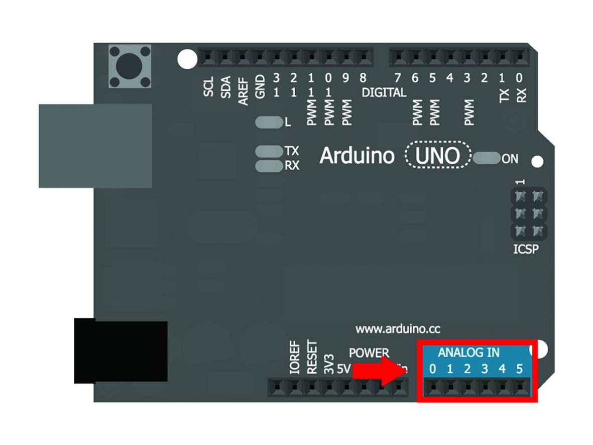
Figure 16-10. The analog input pins of Arduino.
These pins can only be used as inputs, so you don’t need to configure them in the setup block of our sketches. Try, for example, to connect a variable resistor to one of these inputs, as shown in Figure 16-11. Note that the center lead of the potentiometer and the wire that connects to it are both on the other side of the gap from all the other leads.
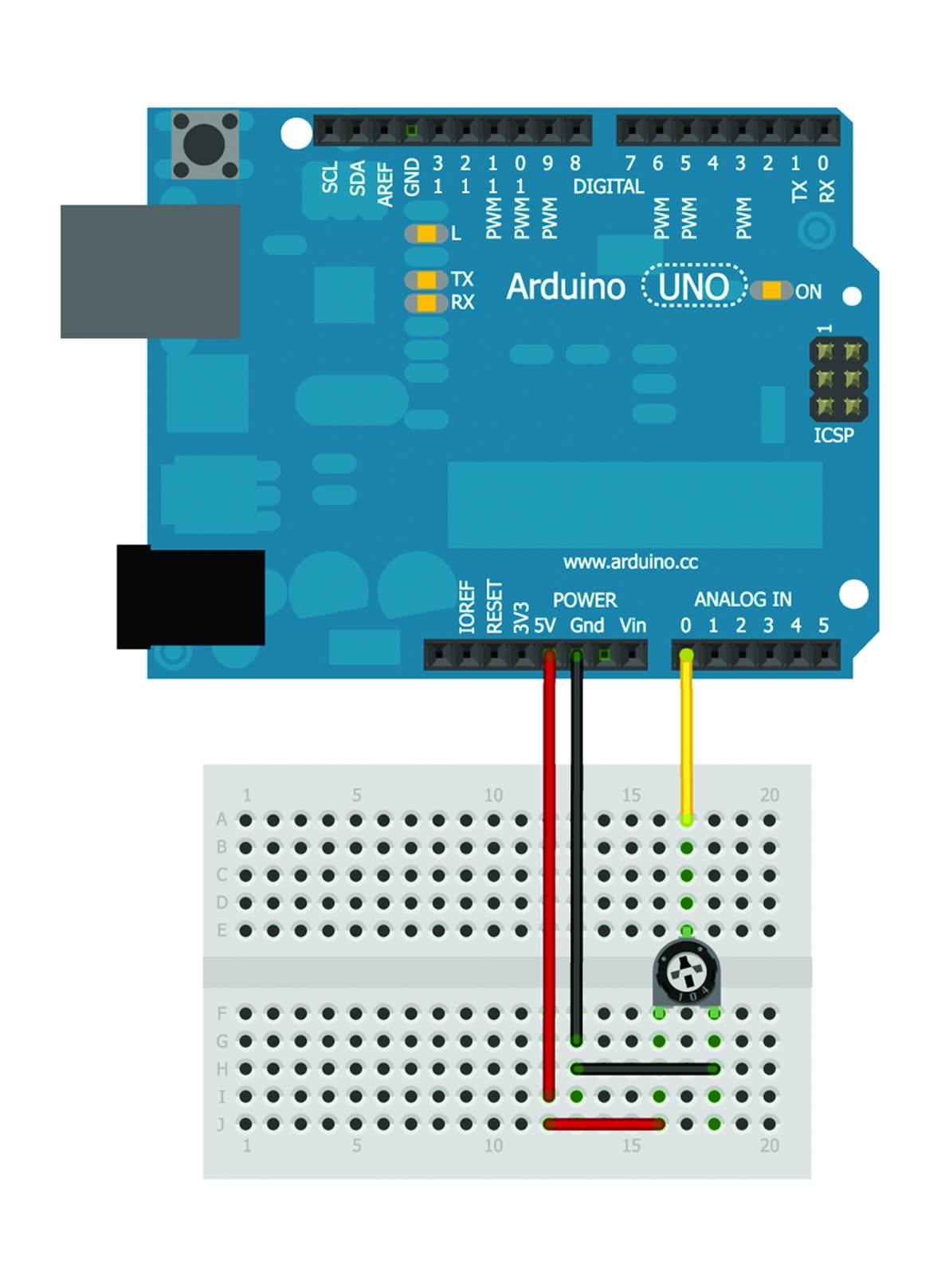
Figure 16-11. A variable resistor connected to an analog pin.
A potentiometer or trimmer is a device that changes its resistance by rotating a knob, exactly like an early volume control. To read the value of this and other analog inputs, you use the analogRead instruction, similar to the corresponding digitalRead, yet analogRead is capable of returning a value between 0 and 1023. Of course, you can store this value in a variable:
int analogValue = analogRead(A0);
How can you use this kind of value? For example, you could change the frequency that the LED blinks at (instead of a trimmer, you could use a proximity sensor and have the LED signaling the approach of a potential danger with increasing intensity). You can connect an LED to pin 13 as before and write the code that corresponds to the behavior you are interested in.
We’re cheating here by not including a resistor between the LED and one of the Arduino pins. Although this technically is stressful on the LED and the Arduino’s pin, we’ve never broken an Arduino doing this. Earlier Arduino models had a built-in resistor on pin 13 (in newer models, that resistor is shunted off to the onboard LED), so we blame this on a habit we picked up in the old days and just haven’t shaken off.
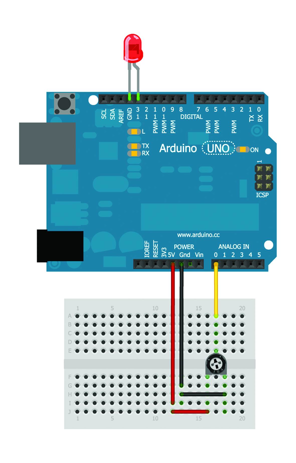
Figure 16-12. an LED and a trimmer ready for use.
You already know how to do everything you need, so you just need to combine what you have learned so far. To show that there’s an LED on pin 13, you’ll write:
int led = 13;
void setup()
{
pinMode(led, OUTPUT);
}
To change the frequency, you need to place the delay between one instruction and the next one stored in a variable, which takes the value read by the trimmer:
interval = analogRead(A0);
The complete listing of the sketch is shown in Example 16-7.
Example 16-7. Using a trimmer to change the delay of a blinking LED
int led = 13;
int interval = 1000;
void setup()
{
pinMode(led, OUTPUT);
}
void loop()
{
interval = analogRead(A0);
digitalWrite(led, HIGH);
delay(interval);
digitalWrite(led, LOW);
delay(interval);
}
Verify and upload the sketch, then try to vary the frequency which the LED blinks at by operating the trimmer or potentiometer knob. When using a variable resistor like this, it helps to set a threshold, i.e. a value below which you don’t want anything to change, as shown in Example 16-8.
Example 16-8. Ignoring all values below a certain threshold
int led = 13;
int interval = 1000;
int threshold = 250;
void setup()
{
pinMode(led, OUTPUT);
}
void loop()
{
interval = analogRead(A0);
if (interval <= threshold)
{
interval = threshold;
}
digitalWrite(led, HIGH);
delay(interval);
digitalWrite(led, LOW);
delay(interval);
}
At first, we define variables: led represents which pin the LED is connected to, interval determines the frequency the LED will blink at, initially equal to 1000, and threshold is the value below which the system behavior doesn’t change.
In the setup, the only thing you need to do is to set the LED pin as an output.
In the loop, you first read the value (analogRead(A0)): if it is less than or equal to the threshold (interval <= threshold), you set the interval variable to the threshold value (interval = threshold). If, on the contrary, the read value is above the threshold, you don’t need to change anything (you just leave the interval at the value you read from analogRead), so there is no else block. Then you make the LED blink.
I Want to Shout It to the World!
The frequency which the LED blinks at gives us an indication of the value the sensor has read. How could you find out the exact value? One possible solution--the simplest one--is to use the serial monitor, a tool built into the Arduino IDE, which allows you to monitor activity on the Arduino’s serial port. How is it used? It’s like being on the phone with a friend: you first have to dial the number and call. In a similar way, to be able and use the serial port on Arduino you have to use the Serial.begin command in the sketch setup:
void setup()
{
Serial.begin(9600);
}
The parameter 9600 indicates the speed that you intend to communicate on the serial port, in this case 9600 bits per second. To write to the serial port, use the Serial.println instruction, where you specify the desired text as a parameter. Basically, it is the equivalent of talking into the phone receiver (anachronistic, yet romantic). A simple sketch for writing the trimmer value to the serial port, keeping the same circuit as in the previous example, is shown in Example 16-9.
Example 16-9. Printing the values read by a trimmer
void setup()
{
Serial.begin(9600);
}
void loop()
{
Serial.println(analogRead(A0));
delay(1000);
}
You have introduced a one-second delay to avoid having too many readings, which would make it harder to understand what is happening. This simple process of writing on the serial port allows Arduino to communicate with the rest of the world and will be very useful for future projects. As for now, we are happy to see the data value that was read. Verify and upload the sketch; then, to open the serial monitor, click the magnifier icon on the top right of the development environment, select Serial Monitor from the Tools menu (Figure 16-13) or press the shortcut key Control-Shift-M (Windows, Linux) or Command-Shift-M (Mac).
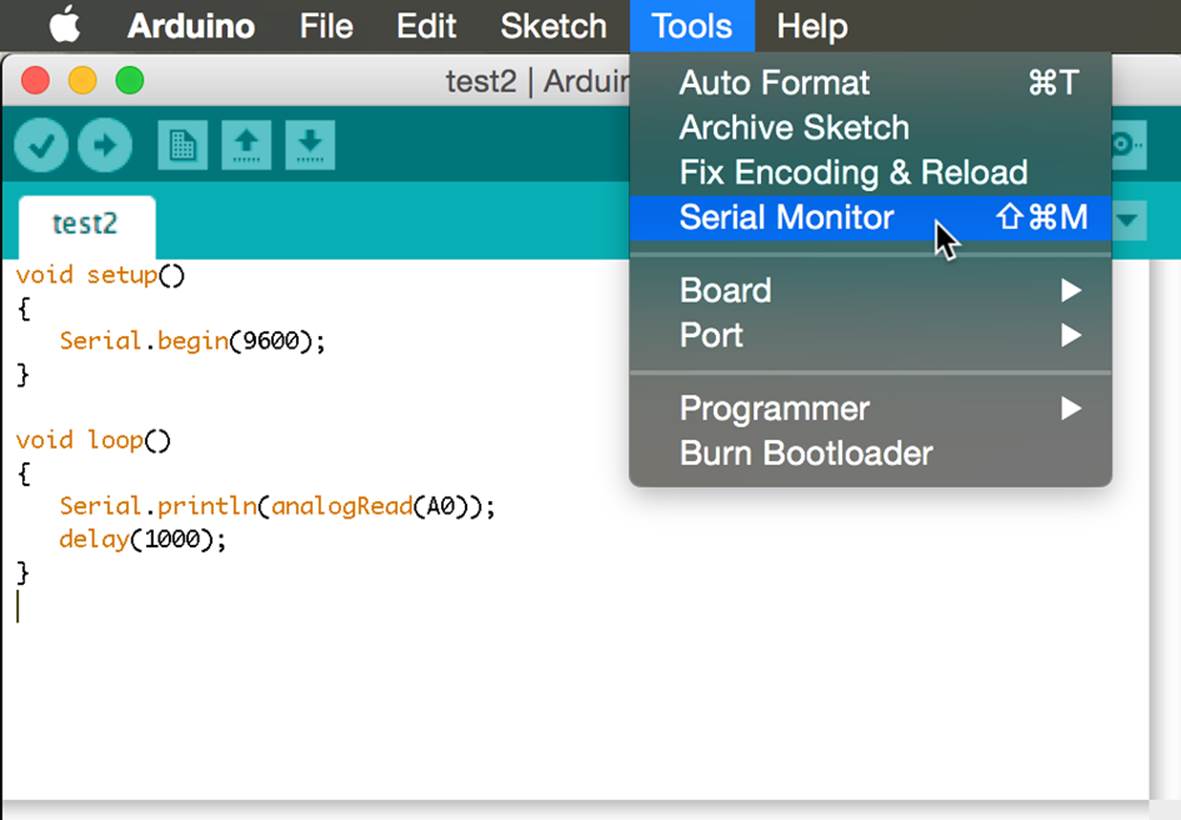
Figure 16-13. Opening the serial monitor.
Once open, the serial monitor will display all the readings it receives from the Arduino. (Figure 16-14).
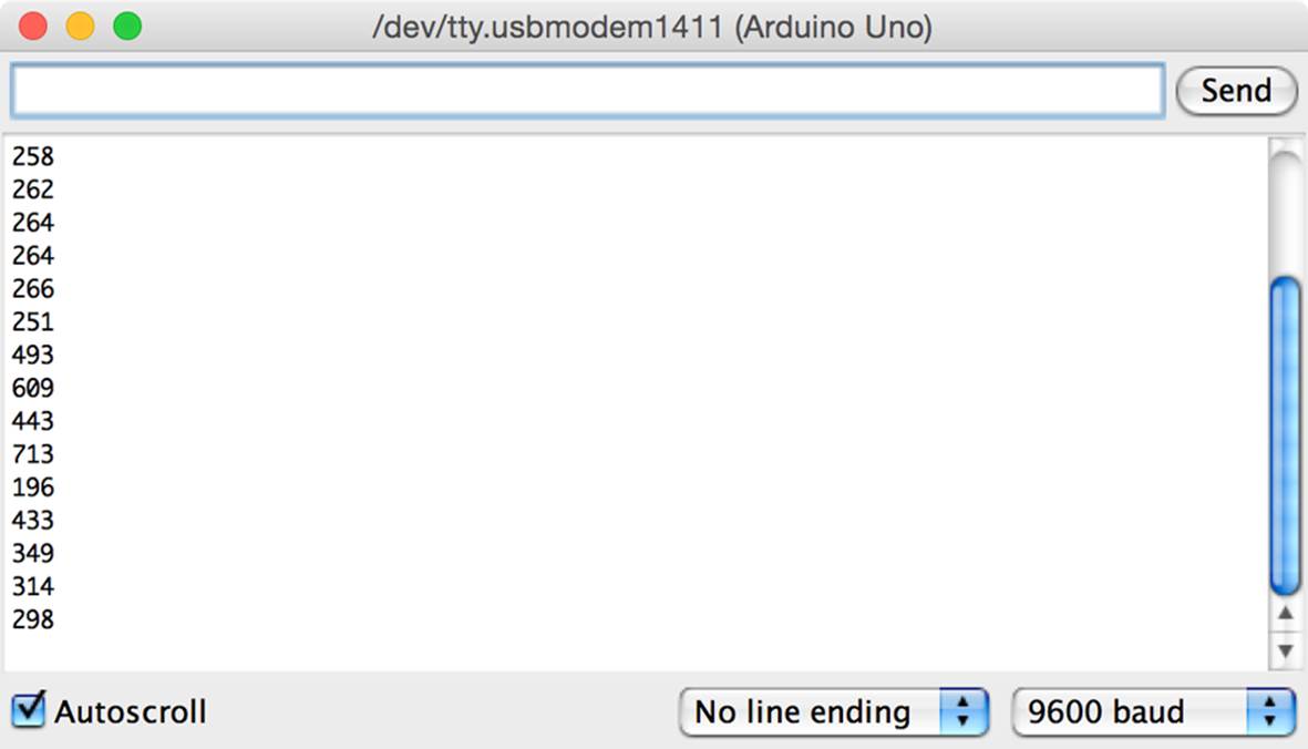
Figure 16-14. Values on the serial monitor.
PWM is Not a Rock Band
Since you can read analog values with the analogRead instruction, you may wonder if there’s a corresponding analogWrite function and how you might use it. As you guessed, this function exists; you need to find out on which pins we can use it. Most of Arduino’s pins are digital only, and the few analog pins are input only. But if you look very carefully at Arduino’s digital pins, you can see a few of them are marked with the letters PWM, which is an acronym for Pulse-Width Modulation. (On some Arduino models, these pins are simply marked with a tilde ~, which roughly looks like the waveform of an analog signal). These pins are firmly digital, yet under the right circumstances they can “pretend” to be analog.
These pins allow you to adjust the intensity of the outgoing signal: as if, rather than having a tap fully open or fully closed, you could decide how open it should be and adjust the water outflow. This is a very useful behavior if you need to operate particular devices like motors, for which you can adjust the rotation speed, or LEDs, for which you can adjust the brightness. How does this work?
It is basically the same idea at the basis of traditional film projectors, which project 24 frames per second:
§ if you only project black frames, the perceived image will be black;
§ if you only project white frames, the perceived image will be white;
§ if you alternate white and black frames, the perceived image will be grey. If you adjust the ratio, say, with two black frames for one white frame, the image will be dark grey. If the ratio is swapped, with two white frames for one black frame, the image will be a lighter grey.
The Arduino allows not just 24, but 256 shades, where at a value of 128, the output is right in the middle. The syntax you need to use if we want to output 128 to pin 9, is:
analogWrite(9, 128);
The first parameter is the pin that concerns us, the second one is the analog value you want to simulate. The analogWrite(9, 0) command corresponds to digitalWrite(9, LOW), whereas analogWrite(9, 255) is equals to digitalWrite(9, HIGH). Figure 16-15 shows the representation of a PWM signal.
You can use this property to fade an LED up and out, by varying its intensity. First, you need to prepare a circuit where the LED is connected to a PWM pin, such as number pin 9 (Figure 16-16).
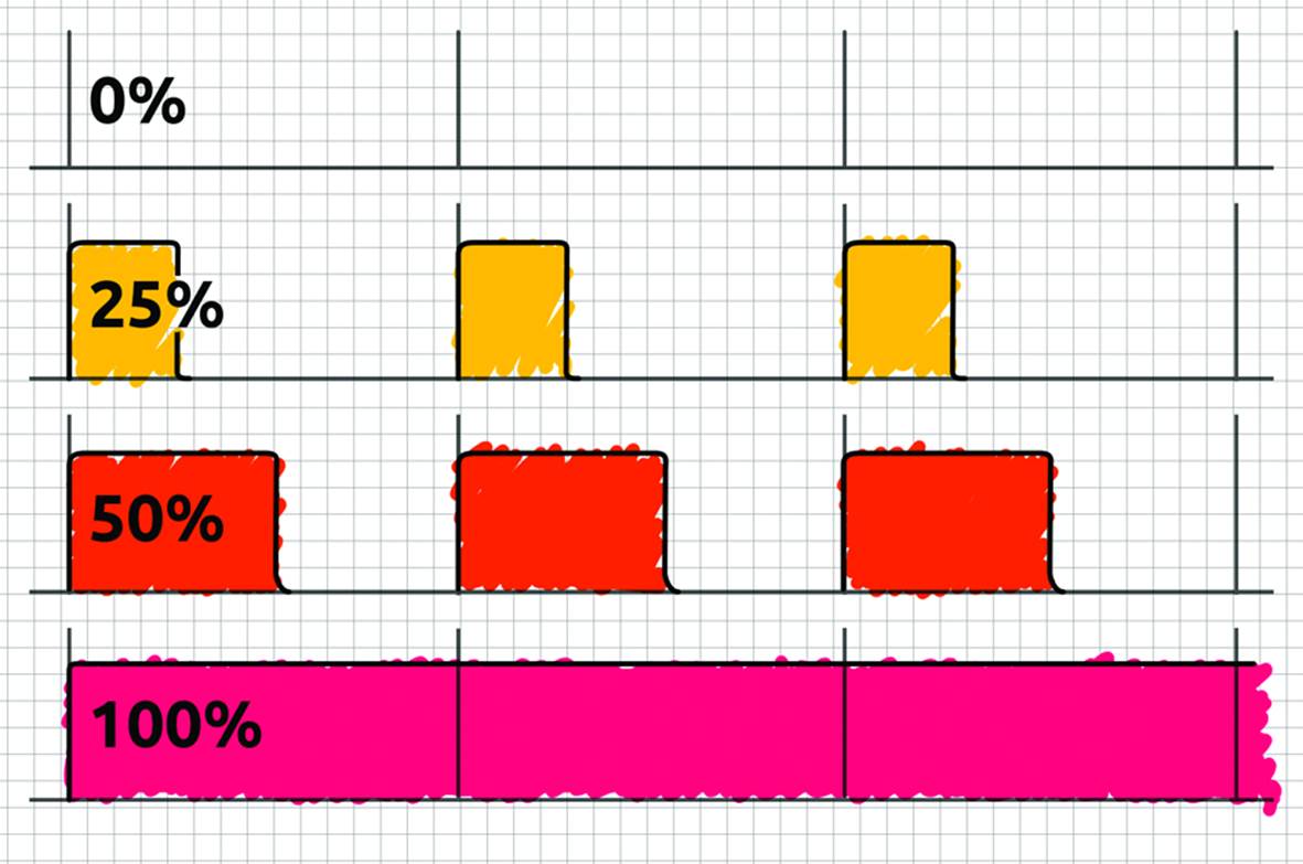
Figure 16-15. Representation of different possible PWM cycles.
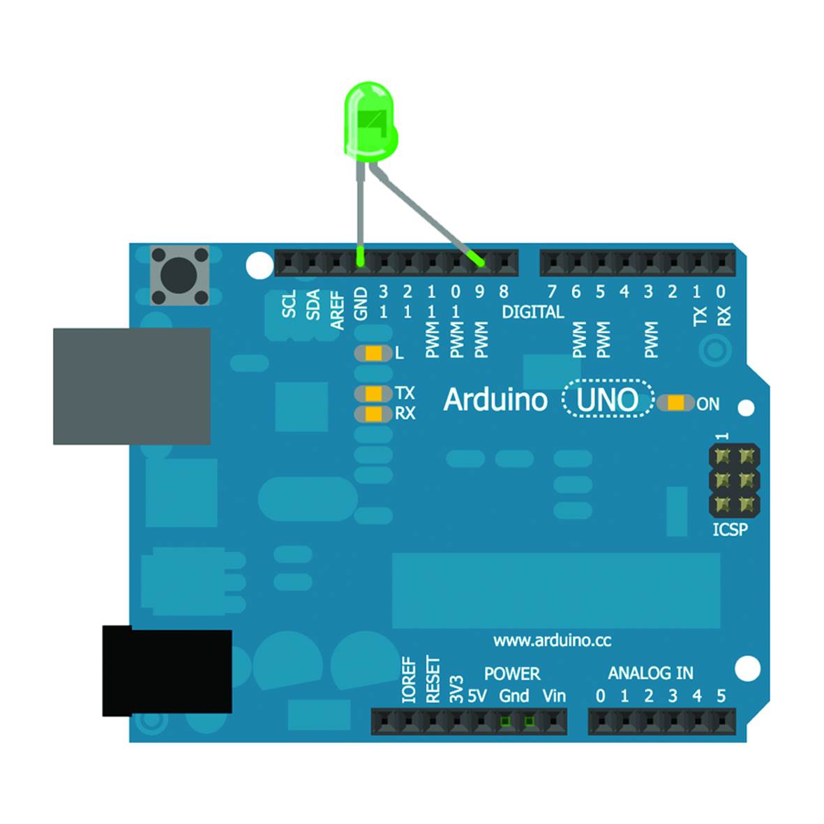
Figure 16-16. An LED connected to a PWM pin.
That pin must be identified as an output in the sketch setup:
int led = 9;
void setup()
{
pinMode(led, OUTPUT);
}
In the loop, you need to start with an intensity value of zero and take it to the maximum (255). For this, you can use a cycle within the main loop block where the counter is also used to denote the LED intensity:
for (int i = 0; i <= 255; i++)
{
analogWrite(led, i);
delay(10);
}
To fade it out you set a similar process, decreasing the counter:
for (int i = 255; i >= 0; i--)
{
analogWrite(led, i);
delay(10);
}
The complete listing of this example is shown in Example 16-10.
Example 16-10. An LED that gradually fades in, up, and out
int led = 9;
void setup()
{
pinMode(led, OUTPUT);
}
void loop()
{
for (int i = 0; i <= 255; i++)
{
analogWrite(led, i);
delay(10);
}
for (int i = 255; i >= 0; i--)
{
analogWrite(led, i);
delay(10);
}
}
If you need any help while writing an Arduino sketch, try the online reference. To view it, click Help on the menu, then Reference.
Some Exercises to Try
Let’s close the chapter with a few things you should try on your own:
1. Make a circuit and a sketch where one LED blinks and another one switches on and off gradually, in the same cycle. When the first LED is on, the second slowly ramps up its brightness; when the second LED arrives at the maximum brightness, the first LED gets turned off, and the second fades out again. Repeat.
2. Make a circuit and a sketch in which you make an LED blink or fade in and out by pressing a button. One press makes the LED fade, two presses makes the LED blink.
3. Make a circuit and a sketch where you can fade an LED in and out through a trimmer or potentiometer, using a maximum of ten possible brightness values. Note: bear in mind the range of values of input (0-1023) and output (0-255) analog signals! A small hint: the map function, which you can find in the online reference, might help;
4. Add a trimmer to the circuit in the previous exercise and edit the sketch so that the delay varies depending on the trimmer value. Plan a minimum delay of 50 milliseconds and a maximum of two and a half seconds.