Learning Internet of Things (2015)
Chapter 8. Creating Protocol Gateways
In the previous chapter, we learned the benefits of creating applications using the Internet of Things (IoT) platform. In this chapter, we will show you how such a platform can be used to bridge different protocols so that devices and applications in different networks that use different protocols can communicate with each other. There may be many reasons why you would need to bridge between protocols in IoT. A few of them are listed here:
· To include services and devices to talk to other services and devices using other protocols if you're interconnecting systems
· To extend the reach of systems and networks to include areas where different protocols are required
· If you're building services using third-party devices
· If you're building devices that third-party services might want to use
· If you're creating an architecture for distributed and open networks for smart buildings or smart cities
· To allow interconnectivity of consumer electronics for IoT
· To enhance the overall interoperability on the Internet
In this chapter, you will learn:
· The benefits of using a good abstraction model for IoT
· How to integrate protocols into such an abstraction model
· How to bridge multiple protocols in real time using an abstraction model
We will show the basics of how the Clayster.Meterig.CoAP module was developed, which is available in the ClaysterSmall platform distribution and introduced in the previous chapter. We will do this in a parallel project called CoapGateway whose source code can be downloaded for free.
Tip
All of the source code presented in this book is available for download. Source code for this chapter and the next can be downloaded here:
https://github.com/Clayster/Learning-IoT-Gateway
Understanding protocol bridging
Consider the problem of creating a simple bridge between two protocols, say XMPP and CoAP introduced in the previous chapters. For a device that communicates through XMPP to be able to interact with a device that uses CoAP, a bridge needs to be inserted in between. This bridge would need to be able to translate requests made using XMPP to a request made using CoAP, then translate the CoAP response back to an XMPP response. In the same way, if a CoAP device wants to request something from an XMPP device, the bridge would need to translate the CoAP request into an XMPP request and then translate the XMPP response back to a CoAP response. It is easy to see we need a pair of translators from one protocol to the other and vice versa.
However, what happens if we want to introduce a third protocol, say MQTT, into the picture? In this case, three pairs of protocol translators would be required: CoAP and XMPP, MQTT and XMPP, and CoAP and MQTT. Another complexity arises with the introduction of MQTT. What happens when protocols do not support the same semantics? CoAP and XMPP support the request/response and event subscription patterns, while XMPP and MQTT support the publish/subscribe pattern. MQTT does not support the request/response and event subscription patterns. How should these differences be handled? One way to handle these patterns in MQTT is for the gateway to buffer the latest reported values and report them immediately if requested, as if the device had supported the corresponding patterns. Another important pattern not supported by MQTT is the point-to-point asynchronous messaging pattern.
Note
Note that some patterns available for these different protocols might be similar, but not equal. The event subscription pattern, for instance, differs from the topic subscription pattern in that it allows clients to subscribe individually to events using individual event triggers. The topic subscription pattern does not support individual event triggers, and the subscribers will have to be contented with the triggers defined by the publisher regardless of the application.
If we want to handle four protocols by including HTTP support, we would need six different protocol translation pairs. Out of these, five protocols would require 10 protocol translation pairs, six protocols would require 15 pairs, seven would require 21 pairs, and so on. In general, if N protocols are supported, N(N – 1)/2 protocol translation pairs would have to be supported. Each time you add support for a protocol, the work becomes more difficult. It is clear that this approach quickly becomes impractical and unsupportable. This can be understood well with the help of the following diagram:
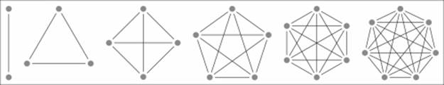
Protocol translation pairs grow as O(N2) without the abstraction model
Using an abstraction model
It is quickly realized that building a protocol gateway by implementing translation pairs between protocols directly is very inefficient and difficult to maintain. A more fruitful path is to use a common abstraction model suitable for IoT and the translation of operations between different protocols. If such an abstraction model is used, translation pairs only need to translate between a given protocol and the abstraction model. This method is more efficient when it comes to implementation and quality assurance than direct translation if more than three different protocols are supported. While translating between two different protocols, you simply need to translate to the common abstraction model first and then use the second translation pair to translate from the abstraction model to the corresponding protocol.
Apart from shortening the development time drastically, a good abstraction model also helps in other ways. It can be used by internal services and administrative processes to administer and communicate with devices regardless of the protocol being used underneath. The CoapGateway project uses the abstraction model provided by the Clayster platform, which was introduced in the previous chapter. As such, it can be used to bridge the CoAP protocol with any other protocol hosted by the platform. Since theClaysterSmall distribution already has support for XMPP through the Clayster.Metering.Xmpp module and MQTT through the Clayster.Metering.Mqtt module, our new CoapGateway project can be used to bridge the CoAP, XMPP, and MQTT protocols. This can be seen in the following diagram:
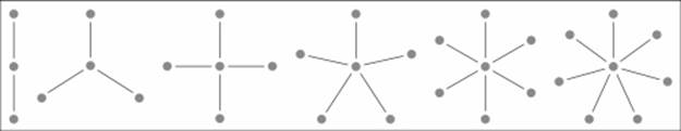
Protocol translation pairs grow as O(N) using an intermediary abstraction model
Note
What is a good abstraction model? The challenging part is to create an abstraction model that is not too concrete. A concrete model might allow you to unknowingly paint yourself into a corner from where you would not be able to move later. This happens when you realize that you need to do something you've never done before, something that is not supported because the model is not sufficiently general. Another challenge is of course to avoid over-abstracting the model, which would make it difficult to use.
Abstraction models will be the point where IoT platforms will distinguish themselves over time. Which platform allows developers to do more over time, taking into consideration that it is not known today what will be developed in the future? Who can provide the most fruitful abstraction model for IoT?
The Clayster IoT platform is based on 20 years of experience in the fields of M2M and IoT; hence, its abstraction model has evolved over time and is easy to use, powerful, and supports a wide range of different use cases. By studying its abstraction model, you are better equipped to determine which platforms suits your long-term requirements.
The basics of the Clayster abstraction model
To understand the implementation of the CoAP protocol bridge in the CoapGateway project, it's important to understand the abstraction model used by Clayster, defined in Clayster.Library.Abstract. To create a protocol bridge, we only need to implement the actual translation between CoAP operations and the abstraction model since the platform does the rest for us.
Understanding editable data sources
In Clayster, you can store objects in the object database, as we have demonstrated earlier. But to manage large quantities of objects in a localized environment, you need to synchronize them across multiple clients and servers in a cluster, import and export them, and so on; this means that more than simple data persistence is required.
For this reason, the basic abstraction model in Clayster starts with a data abstraction model, which defines how configurable data is managed in the system. Data is stored in editable data sources, and each data source is derived from the EditableDataSource class. The keyword "editable" here means the contents can be managed dynamically from both services and management tools, as long as sufficient privileges are granted.
Most data sources in Clayster either store data in editable XML files (EditableXmlFileDataSource) or maintain data in only the memory (EditableInMemoryDataSource), even though developers can easily develop their own types of editable data sources if they wish to.
The system maintains a set of published data sources that can be managed by external tools and services (EditableDataSources). This set is ordered into a tree structure of data sources where each node references a data source (EditableDataSourceReference), as shown in the following diagram:
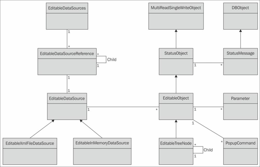
The basic data abstraction model in Clayster
Understanding editable objects
Data in editable data sources comprises editable objects (EditableObject). If a data source contains a single object, it is said to be singular. Flat data sources contain a possibly ordered linear set of objects. However, most data sources contain objects structured into tree structures where each node in the tree is represented by a specialized version of the editable object (EditableTreeNode).
Each editable object is also a status object (StatusObject), an object that maintains a state and a set of status messages (StatusMessage) that are persisted in the object database (DBObject). These status messages can have different life cycles and levels and be of different types, such as informational, warning, error, and exception messages. They can be signed by different operators and are synchronized across the server cluster if available.
Each status object is also an object that can be used in a multithreaded and multiuser environment (MultiReadSingleWriteObject). Through methods in this class, editable objects can be safely managed in an environment where multiple services and users simultaneously work with them, without risking loss of data or inconsistent behavior.
Each editable object has two sets (possible empty) of parameters (Parameter) that control its behavior. One set is used to define the object behavior on the platform side. This set is referred to as the object properties. These properties are synchronized between all the clients and servers in the cluster. The second set is used to configure functionality in any underlying hardware or backend that corresponds to the object. This set is referred to as configurable parameters.
Note
There are many different types of parameters supported by the platform. Each one is managed by a separate class and derived from the Parameter class. They can be found in the Clayster.Library.Abstract.ParameterTypes namespace.
Editable objects can also publish a (possibly empty) set of pop-up commands of different types. There can be simple commands, parameterized commands, and parameterized queries. These context-sensitive commands as well as all the properties, configurable parameters, editable objects, and data sources are available in the management tools, such as Clayster Management Tool (CMT) introduced in the previous chapter, as long as user privileges permit them to.
Using common data sources
Apart from developing services for Clayster, we can control Clayster's functionality by providing new classes of editable objects for existing data sources. This is particularly the case when creating protocol gateways. For this reason, we will provide a short introduction to some of the pre-existing data sources available in Clayster, which might come in handy. You might already be familiar with some of these sources from the previous chapter.
The Users data source contains User objects that correspond to user accounts that can log in to the system. Each user is assigned a role, represented by a Role object in the Roles data source. Each Role object in turn is assigned a set of privileges, and each privilege is represented by a Privilege object in the Privileges data source. This data source is formed as a tree structure of Privilege objects, making it possible for roles to be assigned with all the branches of privileges.
Everything related to communication with devices and processing of sensor data is organized into data sources in the Metering category. The Topology source contains all the devices and how they are connected. The Unit Conversion source contains all unit categories and corresponding units and information about how to convert between compatible units. The Jobs source contains jobs (for instance, readout or report jobs) that can be executed once or regularly. The Groups source allows the logical and geospatial structuring of devices, as opposed to the Topology source that specifies the physical connection structure. Sensor data (or Fields) can be processed by processors defined in the Field Processors data source. They can be stored or otherwise processed through field sinks defined in the Field Sinks data source. Fields can also be imported into the system through objects defined in the Field Imports data source.
Overriding key properties and methods
While creating new editable object classes, you first need to choose an appropriate class to derive your new class from. Since most of the operational functionality is already provided by the platform, all you need to do is override some key properties and methods to provide the information the system needs to have in order to handle objects of the new class properly. You don't need to register created classes anywhere. It's sufficient to declare a class, and the system will automatically find it and be able to use it according to the information provided in these properties and methods.
Following is a brief description of a few central properties and methods that are of interest to us.
Controlling structure
The TagName and Namespace properties are used during serialization and deserialization to identify the class that corresponds to the serialized object. The GetDisplayableTypeName() method can be used to provide a localized human-readable name for the class. TheGetIconResourceName() method can be used to associate the class with one or more icons, depending on the object states. The CanBeAddedTo() and CanTakeNewNode()methods can be used to control where the objects of the corresponding class can appear in a tree structure.
Publishing properties
Object properties are published and managed using a set of four methods. Implementing these four methods will automatically provide support for all the more advanced functions available in the system. These methods are only called when the object has been locked appropriately, corresponding to the operation being performed. So there is no need to worry about multiple threads accessing the object simultaneously in these methods. The GetParametersLocked() method is used to retrieve a set of available parameters. This set will contain sufficient localized metainformation about the properties to be able to provide the end users with a dialog to edit the properties. The GetParameterValueLocked() and SetParameterLocked()methods are used to get and set individual parameter values, while the GetParameterNamesLocked() method can be used to retrieve a list of the available property names.
Publishing commands
All editable objects can publish commands that can be executed either manually or in automation operations. The GetPopupCommands() method returns a set of available commands on an object. Depending on the type of command, different methods are called to execute them. The simplest type of command, one that does not take any parameters, is executed through calls to the ExecuteSimplePopupCommand() method. All other commands require parameters. These parameters are returned from calls to theGetParametersForCommand() method. If it is a normal parameterized command, it is then executed by calling the ExecuteParameterPopupCommand() method. A third type of command, a parameterized query, is executed through calls to the ExecuteParameterPopupQuery()method. These query commands return data to the client asynchronously. This data can be sequences of tabular data, images, or other types of objects.
Handling communication with devices
The Topology data source contains a set of editable objects that are derived from the Node class defined in Clayster.Library.Meters. This class defines common properties and methods that are used to read and configure the corresponding devices.
Reading devices
A node corresponds to a readable device if the IsReadable property returns true. If this is the case, anybody with the correct privileges can request to read the node. This is done by calling the RequestReadout() method. When it is time to read the node, theProcessReadoutRequest() method is called. Who calls this method depends on the hierarchy of nodes in the topology. But it can be assumed a thread has been allocated somewhere if the readout is performed synchronously and that it is now processing the readout request. The corresponding node will be in a read state when this happens, which prohibits any changes to its properties.
Configuring devices
If a device can be written to or configured, the IsWritable property should return true. If it is, anybody (with the corresponding privileges) can request to configure the node accordingly by calling the RequestConfiguration() method. A set of available configurable parameters is returned from the GetConfigurableParametersLocked() method. The IsValidConfiguration() method is called to check whether a corresponding parameter name and value pair is valid. Finally, when a parameter is to be written to the device, theProcessConfiguration() method is called. As in the case of reading the device, the node will be in a read state when this call occurs, and depending on the node hierarchy, a thread will be allocated to execute the method accordingly.
Understanding the CoAP gateway architecture
The CoapGateway architecture is simple and straightforward. The following illustration shows the available classes and their internal relationships. Classes that are colored off-white are defined in Clayster.Library.Abstract. The yellow/orange colored classes are defined in Clayster.Library.Meters and provide the basic functionality for the Topology data source. The blue classes are defined in Clayster.Library.Internet, and in our case, they provide us with communication capabilities. We have used these classes in our previous chapters. The green and pink classes are defined in our CoapGateway project. The color green represents structural nodes, while pink represents classes performing concrete work. All these classes are defined in the .cs files with the same name in the downloadable source code.
To add support for CoAP to the Clayster platform, you need to begin by adding a CoapPort object to the root of the topology. This object performs the actual communication and can also receive incoming requests. It uses a CoapTopologyBridge CoAP resource to publish the available nodes in the topology regardless of the protocol being used. Also, it is accessible by a user account that needs to be provided on the network using the CoAP protocol. This class translates CoAP requests to our common abstraction model and returns CoAP responses to these requests.
The other direction (sending CoAP requests and interpreting CoAP responses) is handled by the CoapServer class and any child nodes added to it. This class is added to the CoapPort class and is derived from IpNode, which provides an IP address and port number property. It is in turn derived from ThreadNode, which provides the execution context for the node and all its children. It also publishes a Scan command that can be evoked to scan the device for available resources. The architecture of the CoAP gateway is shown in the following diagram:
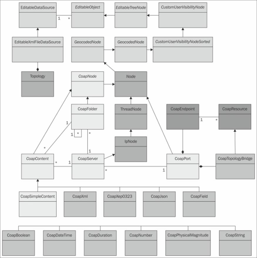
Architecture of the CoAP gateway project
Objects of the CoapServer class accept any number of CoapFolder objects as children. Both CoapServer and CoapFolder objects accept objects that are derived from CoapContent, which means they are resources that can be read. There are simple content resources that report a single data field and complex resources that report sets of fields. Here, you can add any type of class you want to handle different content types.
The existing classes provide a starting point and show how to perform such a translation. The following image shows how the topology can be ordered to read our CoAP sensor created in the Chapter 4, The CoAP Protocol. Since XMPP is supported by the server, all these devices will now automatically be available on the XMPP network as well. The other direction also holds true. Any XMPP devices available in the topology will be available using CoAP as well.
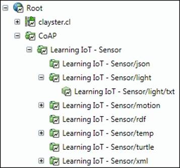
Example topology view of our CoAP sensor
Summary
In this chapter, we introduced how the abstraction models in the IoT service platforms can be used to create protocol gateways. In the next and final chapter, we will discuss security and interoperability in IoT.