Unity in Action: Multiplatform game development in C# with Unity 5 (2015)
Part 1. First steps
Chapter 2. Building a demo that puts you in 3D space
This chapter covers
· Understanding 3D coordinate space
· Putting a player in a scene
· Writing a script that moves objects
· Implementing FPS controls
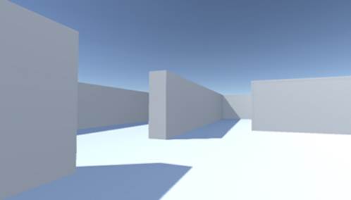
Chapter 1 concluded with the traditional “Hello World!” introduction to a new programming tool; now it’s time to dive into a nontrivial Unity project, a project with interactivity and graphics. You’ll put some objects into a scene and write code to enable a player to walk around that scene. Basically, it’ll be Doom without the monsters (something like what figure 2.1 depicts). The visual editor in Unity enables new users to start assembling a 3D prototype right away, without needing to write a lot of boilerplate code first (for things like initializing a 3D view or establishing a rendering loop).
Figure 2.1. Screenshot of the 3D demo (basically, Doom without the monsters)
It’s tempting to immediately start building the scene in Unity, especially with such a simple (in concept!) project. But it’s always a good idea to pause at the beginning and plan out what you’re going to do, and this is especially important right now because you’re new to the process.
2.1. Before you start...
Unity makes it easy for a newcomer to get started, but let’s go over a couple of points before you build the complete scene. Even when working with a tool as flexible as Unity, you do need to have some sense of the goal you’re working toward. You also need a grasp of how 3D coordinates operate or you could get lost as soon as you try to position an object in the scene.
2.1.1. Planning the project
Before you start programming anything, you always want to pause and ask yourself, “So what am I building here?” Game design is a huge topic unto itself, with many impressively large books focused on how to design a game. Fortunately for our purposes, you only need a brief outline of this simple demo in mind in order to develop a basic learning project. These initial projects won’t be terribly complex designs anyway, in order to avoid distracting you from learning programming concepts; you can (and should!) worry about higher-level design issues after you’ve mastered the fundamentals of game development.
For this first project you’ll build a basic FPS (first-person shooter) scene. There will be a room to navigate around, players will see the world from their character’s point of view, and the player can control the character using the mouse and keyboard. All the interesting complexity of a complete game can be stripped away for now in order to concentrate on the core mechanic: moving around in a 3D space. Figure 2.2 depicts the roadmap for this project, basically laying out the mental checklist I built in my head:
Figure 2.2. Roadmap for the 3D demo
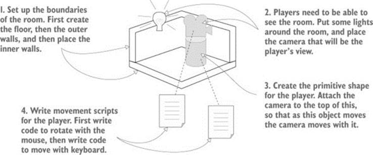
1. Set up the room: create the floor, outer walls, and inner walls.
2. Place the lights and camera.
3. Create the player object (including attaching the camera on top).
4. Write movement scripts: rotate with the mouse and move with the keyboard.
Don’t be scared off by everything in this roadmap! It sounds like there’s a lot in this chapter, but Unity makes it easy. The upcoming sections about movement scripts are so extensive only because we’ll be going through every line to understand all the concepts in detail. This project is a first-person demo in order to keep the art requirements simple; because you can’t see yourself, it’s fine for “you” to be a cylindrical shape with a camera on top! Now you just need to understand how 3D coordinates work, and it will be easy to place everything in the visual editor.
2.1.2. Understanding 3D coordinate space
If you think about the simple plan we’re starting with, there are three aspects to it: a room, a view, and controls. All of those items rely on you understanding how positions and movements are represented in 3D computer simulations, and if you’re new to working with 3D graphics you might not already know that stuff.
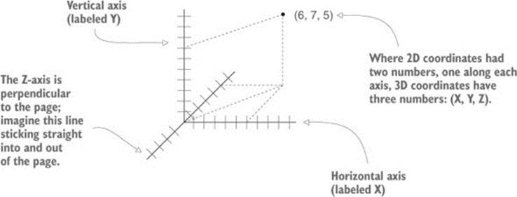
It all boils down to numbers that indicate points in space, and the way those numbers correlate to the space is through coordinate axes. If you think back to math class, you’ve probably seen and used X- and Y-axes (see figure 2.3) for assigning coordinates to points on the page, which is referred to as a Cartesian coordinate system.
Figure 2.3. Coordinates along the X- and Y-axes define a 2D point.

Two axes give you 2D coordinates, with all points in the same plane. Three axes are used to define 3D space. Because the X-axis goes along the page horizontally and the Y-axis goes along the page vertically, we now imagine a third axis that sticks straight into and out of the page, perpendicular to both the X and Y axes. Figure 2.4 depicts the X-, Y-, and Z-axes for 3D coordinate space. Everything that has a specific position in the scene will have XYZ coordinates: position of the player, placement of a wall, and so forth.
Figure 2.4. Coordinates along the X-, Y-, and Z-axes define a 3D point.
In Unity’s Scene view you can see these three axes displayed, and in the Inspector you can type in the three numbers to position an object. Not only will you write code to position objects using these three-number coordinates, but you can also define movements as a distance to move along each axis.
Left-handed vs. right-handed coordinates
The positive and negative direction of each axis is arbitrary, and the coordinates still work no matter which direction the axes point. You simply need to stay consistent within a given 3D graphics tool (animation tool, game development tool, and so forth).
But in almost all cases X goes to the right and Y goes up; what differs between different tools is whether Z goes into or comes out of the page. These two directions are referred to as “left-handed” or “right-handed”; as this figure shows, if you point your thumb along the X-axis and your index finger along the Y-axis, then your middle finger points along the Z-axis.
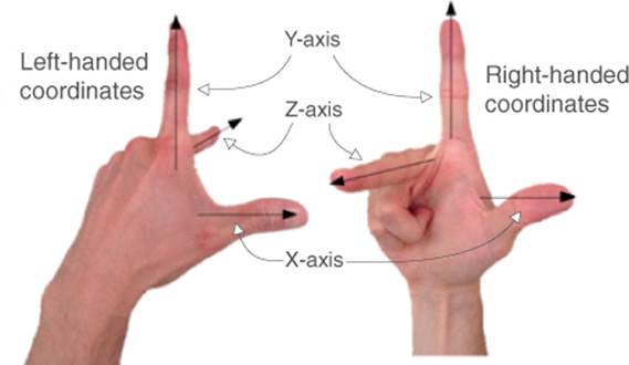
The Z-axis points in a different direction on the left hand versus the right hand.
Unity uses a left-handed coordinate system, as do many 3D art applications. Many other tools use right-handed coordinate systems (OpenGL, for example), so don’t get confused if you ever see different coordinate directions.
Now that you have a plan in mind for this project and you know how coordinates are used to position objects in 3D space, it’s time to start building the scene.
2.2. Begin the project: place objects in the scene
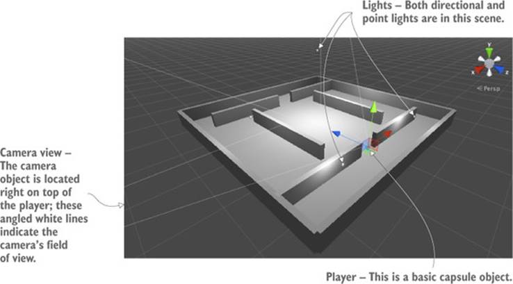
All right, let’s create and place objects in the scene. First you’ll set up all the static scenery—the floor and walls. Then you’ll place lights around the scene and position the camera. Last you’ll create the object that will be the player, the object to which you’ll attach scripts to walk around the scene. Figure 2.5 shows what the editor will look like with everything in place.
Figure 2.5. Scene in the Editor with floor, walls, lights, a camera, and the player
Chapter 1 showed how to create a new project in Unity, so you’ll do that now. Remember: Choose File > New Project and then name your new project in the window that pops up. After creating the new project, immediately save the current empty default scene, because the project doesn’t have any Scene file initially. The scene starts out empty, and the first objects to create are the most obvious ones.
2.2.1. The scenery: floor, outer walls, inner walls
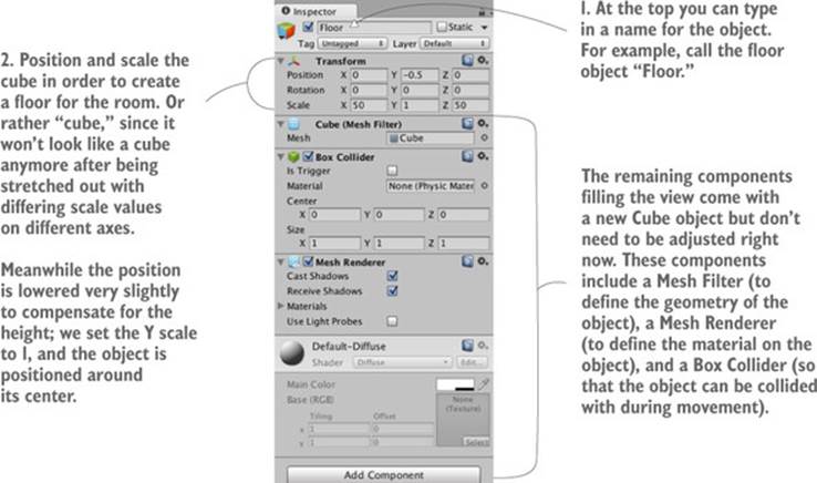
Select the GameObject menu at the top of the screen, and then hover over 3D Object to see that drop-down menu. Select Cube to create a new cube object in the scene (later we’ll use other shapes like Sphere and Capsule). Adjust the position and scale of this object, as well as its name, in order to make the floor; figure 2.6 shows what values the floor should be set to in the Inspector (it’s only a cube initially, before you stretch it out).
Figure 2.6. Inspector view for the floor
Note
The numbers for position can be any units you want, as long as you’re consistent throughout the scene. The most common choice for units is meters and that’s what I generally choose, but I also use feet sometimes and I’ve even seen other people decide that the numbers are inches!
Repeat the same steps in order to create outer walls for the room. You can create new cubes each time, or you can copy and paste existing objects using the standard shortcuts. Move, rotate, and scale the walls to form a perimeter around the floor, as shown in figure 2.5. Experiment with different numbers (for example, 1, 4, 50 for scale) or use the transform tools first seen in section 1.2.2 (remember that the mathematical term for moving and rotating in 3D space is “transform”).
Tip
Also recall the navigation controls so that you can view the scene from different angles or zoom out for a bird’s-eye view. If you ever get lost in the scene, press F to reset the view on the currently selected object.
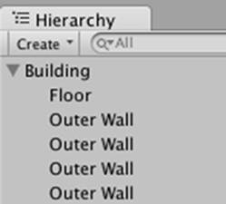
The exact transform values the walls end up with will vary depending on how you rotate and scale the cubes in order to fit, and on how the objects are linked together in the Hierarchy view. For example, in figure 2.7 the walls are all children of an empty root object, so that the Hierarchy list will look organized. If you need an example to copy working values from, download the sample project and refer to the walls there.
Figure 2.7. The Hierarchy view showing the walls and floor organized under an empty object
Tip
Drag objects on top of each other in the Hierarchy view to establish linkages. Objects that have other objects attached are referred to as parent; objects attached to other objects are referred to as children. When the parent object is moved (or rotated or scaled), the child objects are transformed along with it.
Tip
Empty game objects can be used to organize the scene in this way. By linking visible objects to a root object, their Hierarchy list can be collapsed. Be warned: before linking any child objects to it, you want to position the empty root object at 0, 0, 0 to avoid any positioning oddities later.
What is GameObject?
All scene objects are instances of the class GameObject, similar to how all script components inherit from the class MonoBehaviour. This fact was more explicit with the empty object actually named GameObject but is still true regardless of whether the object is named Floor, Camera, or Player.
GameObject is really just a container for a bunch of components. The main purpose of GameObject is so that MonoBehaviour has something to attach to. What exactly the object is in the scene depends on what components have been added to that GameObject. Cube objects have a Cube component, Sphere objects have a Sphere component, and so on.
Once the outer walls are in place, create some inner walls to navigate around. Position the inner walls however you like; the idea is to create some hallways and obstacles to walk around once you write code for movement.
Now the scene has a room in it, but without any lights the player won’t be able to see any of it. Let’s take care of that next.
2.2.2. Lights and cameras
Typically you light a 3D scene with a directional light and then a series of point lights. First start with a directional light; the scene probably already has one by default, but if not then create one by choosing GameObject > Light and selecting Directional Light.
Types of lights
You can create several types of light sources, defined by how and where they project light rays. The three main types are point, spot, and directional.
Point lights are a kind of light source where all the light rays originate from a single point and project out in all directions, like a lightbulb in the real world. The light is brighter up close because the light rays are bunched up.
Spot lights are a kind of light source where all the light rays originate from a single point but only project out in a limited cone. No spot lights are used in the current project, but these lights are commonly used to highlight parts of a level.
Directional lights are a kind of light source where all the light rays are parallel and project evenly, lighting everything in the scene the same way. This is like the sun in the real world.
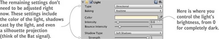
The position of a directional light doesn’t affect the light cast from it, only the rotation the light source is facing, so technically you could place that light anywhere in the scene. I recommend placing it high above the room so that it intuitively feels like the sun and so that it’s out of the way when you’re manipulating the rest of the scene. Rotate this light and watch the effect on the room; I recommend rotating it slightly on both the X- and Y-axes to get a good effect. You can see an Intensity setting when you look in the Inspector (see figure 2.8). As the name implies, that setting controls the brightness of the light. If this were the only light, it’d have to be more intense, but because you’ll add a bunch of point lights as well, this directional light can be pretty dim, like 0.6 Intensity.
Figure 2.8. Directional light settings in the Inspector
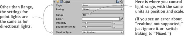
As for point lights, create several using the same menu and place them around the room in dark spots in order to make sure all the walls are lit. You don’t want too many (performance will degrade if the game has lots of lights), but one near each corner should be fine (I suggest raising them to the tops of the walls), plus one placed high above the scene (like a Y of 18) to give some variety to the light in the room. Note that point lights have a setting for Range added to the Inspector (see figure 2.9). This controls how far away the light reaches; whereas directional lights cast light evenly throughout the entire scene, point lights are brighter when an object is closer. The point lights lower to the floor should have a range around 18, but the light placed high up should have a range of around 40 in order to reach the entire room.
Figure 2.9. Point light settings in the Inspector
The other kind of object needed in order for the player to see the scene is a camera, but the “empty” scene already came with a main camera, so you’ll use that. If you ever need to create new cameras (such as for split-screen views in multiplayer games), Camera is another choice in the same GameObject menu as Cube and Lights. The camera will be positioned around the top of the player so that the view appears to be the player’s eyes.
2.2.3. The player’s collider and viewpoint
For this project, a simple primitive shape will do to represent the player. In the GameObject menu (remember, hover over 3D Object to expand the menu) click Capsule. Unity creates a cylindrical shape with rounded ends; this primitive shape will represent the player. Position this object at 1.1 on the Y-axis (half the height of the object, plus a bit to avoid overlapping the floor). You can move the object on X and Z wherever you like, as long as it’s inside the room and not touching any walls. Name the object Player.
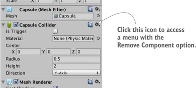
In the Inspector you’ll notice that this object has a capsule collider assigned to it. That’s a logical default choice for a capsule object, just like cube objects had a box collider by default. But this particular object will be the player and thus needs a slightly different sort of component than most objects. Remove the capsule collider by clicking the gear icon toward the top-right of that component, shown in figure 2.10; that will display a menu that includes the option Remove Component. The collider is a green mesh surrounding the object, so you’ll see the green mesh disappear after deleting the capsule collider.
Figure 2.10. Removing a component in the Inspector
Instead of a capsule collider we’re going to assign a character controller to this object. At the bottom of the Inspector there’s a button labeled Add Component; click that button to open a menu of components that you can add. In the Physics section of this menu you’ll find Character Controller; select that option. As the name implies, this component will allow the object to behave like a character.
You need to complete one last step to set up the player object: attaching the camera. As mentioned in the earlier section on floors and walls, objects can be dragged onto each other in the Hierarchy view. Drag the camera object onto the player capsule to attach the camera to the player. Now position the camera so that it’ll look like the player’s eyes (I suggest a position of 0, 0.5, 0). If necessary, reset the camera’s rotation to 0, 0, 0 (this will be off if you rotated the capsule).
You’ve created all the objects needed for this scene. What remains is writing code to move the player object.
2.3. Making things move: a script that applies transforms
To have the player walk around the scene, you’ll write movement scripts attached to the player. Remember, components are modular bits of functionality that you add to objects, and scripts are a kind of component. Eventually those scripts will respond to keyboard and mouse input, but first just make the player spin in place. This beginning will teach you how to apply transforms in code. Remember that the three transforms are Translate, Rotate, and Scale; spinning an object means changing the rotation. But there’s more to know about this task than just “this involves rotation.”
2.3.1. Diagramming how movement is programmed
Animating an object (such as making it spin) boils down to moving it a small amount every frame, with the frames playing over and over. By themselves transforms apply instantly, as opposed to visibly moving over time. But applying the transforms over and over causes the object to visibly move, just like a series of still drawings in a flipbook. Figure 2.11 diagrams how this works.
Figure 2.11. The appearance of movement: cyclical process of transforming between still pictures
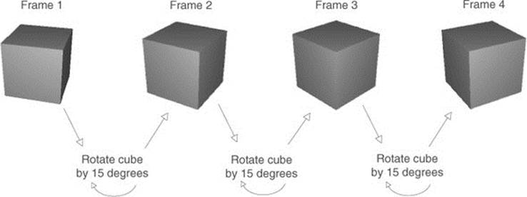
Recall that script components have an Update() method that runs every frame. To spin the cube, add code inside Update() that rotates the cube a small amount. This code will run over and over every frame. Sounds pretty simple, right?
2.3.2. Writing code to implement the diagram
Now let’s put in action the concepts just discussed. Create a new C# script (remember it’s in the Create submenu of the Assets menu), name it Spin, and write in the code from the following listing (don’t forget to save the file after typing in it!).
Listing 2.1. Making the object spin
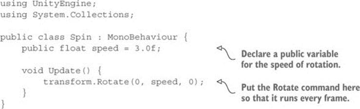
To add the script component to the player object, drag the script up from the Project view and drop it onto Player in the Hierarchy view. Now hit Play and you’ll see the view spin around; you’ve written code to make an object move! This code is pretty much the default template for a new script plus two new added lines, so let’s examine what those two lines do.
First there’s the variable for speed added toward the top of the class definition. There are two reasons for defining the rotation speed as a variable: one is the standard “no magic numbers” programming rule, and the second reason is specific to how Unity displays public variables. Unity does something handy with public variables in script components, as described in the following tip.
Tip
Public variables are exposed in the Inspector so that you can adjust the component’s values after adding a component to a game object. This is referred to as “serializing” the value, because Unity saves the modified state of the variable.
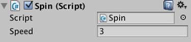
Figure 2.12 shows what the script component looks like in the Inspector. You can type in a new number, and then the script will use that value instead of the default value defined in the code. This is a handy way to adjust settings for the component on different objects, working within the visual editor instead of hardcoding every value.
Figure 2.12. The Inspector displaying a public variable declared in the script
The second line to examine from listing 2.1 is the Rotate() method. That’s inside Update() so that the command runs every frame. Rotate() is a method of the Transform class, so it’s called with dot notation through the transform component of this object (as in most object-oriented languages, this.transform is implied if you type transform). The transform is rotated by speed degrees every frame, resulting in a smooth spinning movement. But why are the parameters to Rotate() listed as (0, speed, 0) as opposed to, say, (speed, 0, 0)?
Recall that there are three axes in 3D space, labeled X, Y, and Z. It’s fairly intuitive to understand how these axes relate to positions and movements, but these axes can also be used to describe rotations. Aeronautics describes rotations in a similar way, so programmers working with 3D graphics often use a set of terms borrowed from aeronautics: pitch, yaw, and roll. Figure 2.13 illustrates what these terms mean; pitch is rotation around the X-axis, yaw is rotation around the Y-axis, and roll is rotation around the Z-axis.
Figure 2.13. Illustration of pitch, yaw, and roll rotation of an aircraft
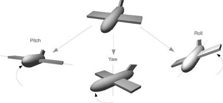
Given that we can describe rotations around the X-, Y-, and Z-axes, that means the three parameters for Rotate() are X, Y, and Z rotation. Because we only want the player to spin around sideways, as opposed to tilting up and down, there should only be a number given for the Y rotation, and just 0 for X and Z rotation. Hopefully you can guess what will happen if you change the parameters to (speed, 0, 0) and then play it; try that now!
There’s one other subtle point to understand about rotations and 3D coordinate axes, embodied in an optional fourth parameter to the Rotate() method.
2.3.3. Local vs. global coordinate space
By default, the Rotate() method operates on what are called local coordinates. The other kind of coordinates you could use are global. You tell the method whether to use local or global coordinates using an optional fourth parameter by writing either Space.Self or Space.World like so:
Rotate(0, speed, 0, Space.World)
Refer back to the explanation about 3D coordinate space, and ponder these questions: Where is (0, 0, 0) located? What direction is the X-axis pointed in? Can the coordinate system itself move around?
It turns out that every single object has its own origin point, as well as its own direction for the three axes, and this coordinate system moves around with the object. This is referred to as local coordinates. The overall 3D scene also has its own origin point and its own direction for the three axes, and this coordinate system never moves. This is referred to as global coordinates. Thus, when you specify local or global for the Rotate() method, you’re telling it whose X-, Y-, and Z-axes to rotate around (see figure 2.14).
Figure 2.14. Local vs. global coordinate axes
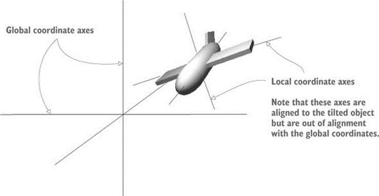
If you’re new to 3D graphics, this is somewhat of a mind-bending concept. The different axes are depicted in figure 2.14 (notice how “left” to the plane is a different direction than “left” to the world) but the easiest way to understand local and global is through an example.
First, select the player object and then tilt it a bit (something like 30 for X rotation). This will throw off the local coordinates, so that local and global rotations will look different. Now try running the Spin script both with and without Space.World added to the parameters; if it’s too hard for you to visualize what’s happening, try removing the spin component from the player object and instead spin a tilted cube placed in front of the player. You’ll see the object rotating around different axes when you set the command to local or global coordinates.
2.4. Script component for looking around: MouseLook
Now you’ll make rotation respond to input from the mouse (that is, rotation of the object this script is attached to, which in this case will be the player). You’ll do this in several steps, progressively adding new movement abilities to the character. First the player will only rotate side to side, and then the player will only rotate up and down. Eventually the player will be able to look around in all directions (rotating horizontally and vertically at the same time), a behavior referred to as mouse-look.
Given that there will be three different types of rotation behavior (horizontal, vertical, and both), you’ll start by writing the framework for supporting all three. Create a new C# script, name it MouseLook, and write in the code from the next listing.
Listing 2.2. MouseLook framework with enum for the Rotation setting
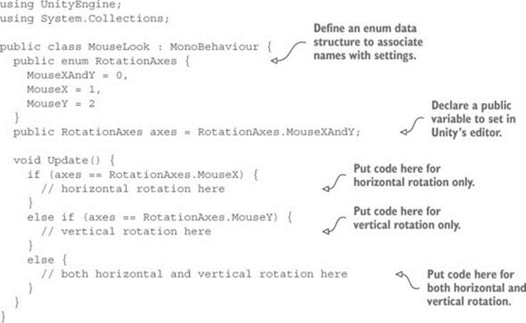
Notice that an enum is used to choose horizontal or vertical rotation for the Mouse-Look script. Defining an enum data structure allows you to set values by name, rather than typing in numbers and trying to remember what each number means (is 0 horizontal rotation? Is it 1?). If you then declare a public variable typed to that enum, that will display in the Inspector as a drop-down menu (see figure 2.15), which is useful for selecting settings.
Figure 2.15. The Inspector displays public enum variables as a drop-down menu.
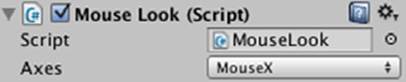
Remove the Spin component (the same way you removed the capsule collider earlier) and attach this new script to the player object instead. Use the Axes menu to switch between code branches while working through the code. With the horizontal/vertical rotation setting in place, you can fill in code for each branch of the conditional.
2.4.1. Horizontal rotation that tracks mouse movement
The first and simplest branch is horizontal rotation. Start by writing the same rotation command you used in listing 2.1 to make the object spin. Don’t forget to declare a public variable for the rotation speed; declare the new variable after axes but before Update(), and call the variablesensitivityHor because speed is too generic a name once you have multiple rotations involved. Increase the value of the variable to 9 this time because that value needs to be bigger once the code starts scaling it (which will be soon). The adjusted code should look like the following listing.
Listing 2.3. Horizontal rotation, not yet responding to the mouse
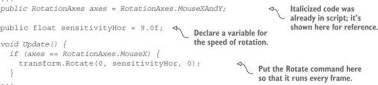
If you play the script now, the view will spin around just like before (only a lot faster, because the Y rotation is 9 instead of 3). The next step is to make the rotation react to mouse movement, so let’s introduce a new method: Input.GetAxis(). The Input class has a bunch of methods for handling input devices (such as the mouse) and the method GetAxis() returns numbers correlated to the movement of the mouse (positive or negative, depending on the direction of movement). GetAxis() takes the name of the axis desired as a parameter, and the horizontal axis is called Mouse X.
If you multiply the rotation speed by the axis value, the rotation will respond to mouse movement. The speed will scale according to mouse movement, scaling down to zero or even reversing direction. The Rotate command now looks like the next listing.
Listing 2.4. Rotate command adjusted to respond to the mouse
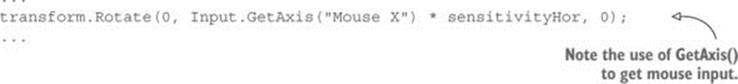
Hit Play and then move the mouse around. As you move the mouse from side to side, the view will rotate from side to side. That’s pretty cool! The next step is to rotate vertically instead of horizontally.
2.4.2. Vertical rotation with limits
For horizontal rotation we’ve been using the Rotate() method, but we’ll take a different approach with vertical rotation. Although that method is convenient for applying transforms, it’s also kind of inflexible. It’s only useful for incrementing the rotation without limit, which was fine for horizontal rotation, but vertical rotation needs limits on how much the view can tilt up or down. The following listing shows the vertical rotation code for MouseLook; a detailed explanation of the code will come right after.
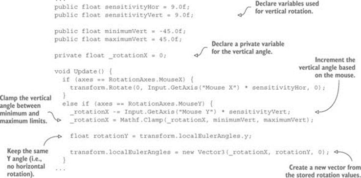
Listing 2.5. Vertical rotation for MouseLook
Set the Axes menu of the MouseLook component to vertical rotation and play the new script. Now the view won’t rotate sideways, but it’ll tilt up and down when you move the mouse up and down. The tilt stops at upper and lower limits.
There are several new concepts in this code that need to be explained. First off, we’re not using Rotate() this time, so we need a variable (called _rotationX here, because vertical rotation goes around the X-axis) in which to store the rotation angle. The Rotate() method increments the current rotation, whereas this code sets the rotation angle directly. In other words, it’s the difference between saying “add 5 to the angle” and “set the angle to 30.” We do still need to increment the rotation angle, but that’s why the code has the -= operator: to subtract a value from the rotation angle, rather than set the angle to that value. By not using Rotate() we can manipulate the rotation angle in various ways aside from only incrementing it. The rotation value is multiplied by Input.GetAxis() just like in the code for horizontal rotation, except now we ask for Mouse Y because that’s the vertical axis of the mouse.
The rotation angle is manipulated further on the very next line. We use Mathf.Clamp() to keep the rotation angle between minimum and maximum limits. Those limits are public variables declared earlier in the code, and they ensure that the view can only tilt 45 degrees up or down. TheClamp() method isn’t specific to rotation, but is generally useful for keeping a number variable between limits. Just to see what happens, try commenting out the Clamp() line; now the tilt doesn’t stop at upper and lower limits, allowing you to even rotate completely upside down! Clearly, viewing the world upside down is undesirable; hence the limits.
Because the angles property of transform is a Vector3, we need to create a new Vector3 with the rotation angle passed in to the constructor. The Rotate() method was automating this process for us, incrementing the rotation angle and then creating a new vector.
Definition
A vector is multiple numbers stored together as a unit. For example, a Vector3 is 3 numbers (labeled x, y, z).
Warning
The reason why we need to create a new Vector3 instead of changing values in the existing vector in the transform is because those values are read-only for transforms. This is a common mistake that can trip you up.
Euler angles vs. quaternion
You’re probably wondering why the property is called localEulerAngles and not localRotation. First you need to know about a concept called quaternions.
Quaternions are a different mathematical construct for representing rotations. They’re distinct from Euler angles, which is the name for the X-, Y-, Z-axes approach we’ve been taking. Remember the whole discussion of pitch, yaw, and roll? Well, that method of representing rotations is Euler angles. Quaternions are...different. It’s hard to explain what quaternions are, because they’re an obscure aspect of higher math, involving movement through four dimensions. If you want a detailed explanation, try reading the document found here:
www.flipcode.com/documents/matrfaq.html#Q47
It’s a bit easier to explain why quaternions are used to represent rotations: interpolating between rotation values (that is, going through a bunch of in-between values to gradually change from one value to another) looks smoother and more natural when using quaternions.
To return to the initial question, it’s because localRotation is a quaternion, not Euler angles. Unity also provides the Euler angles property to make manipulating rotations easier to understand; the Euler angles property is converted to and from quaternion values automatically. Unity handles the harder math for you behind the scenes, so you don’t have to worry about handling it yourself.
There’s one more rotation setting for MouseLook that needs code: horizontal and vertical rotation at the same time.
2.4.3. Horizontal and vertical rotation at the same time
This last chunk of code won’t use Rotate() either, for the same reason: the vertical rotation angle is clamped between limits after being incremented. That means the horizontal rotation needs to be calculated directly now. Remember, Rotate() was automating the process of incrementing the rotation angle (see the next listing).
Listing 2.6. Horizontal and vertical MouseLook
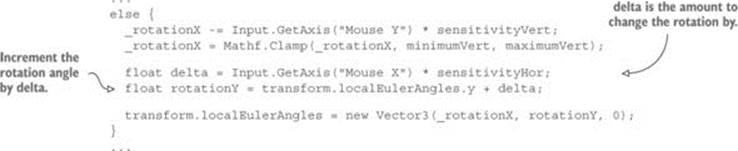
The first couple of lines, dealing with _rotationX, are exactly the same as in the last section. Just remember that rotating around the object’s X-axis is vertical rotation. Because horizontal rotation is no longer being handled using the Rotate() method, that’s what the delta androtationY lines are doing. Delta is a common mathematical term for “the amount of change,” so our calculation of delta is the amount that rotation should change. That amount of change is then added to the current rotation angle to get the desired new rotation angle.
Finally, both angles, vertical and horizontal, are used to create a new vector that’s assigned to the transform component’s angle property.
Disallow physics rotation on the player
Although this doesn’t matter quite yet for this project, in most modern FPS games there’s a complex physics simulation affecting everything in the scene. This will cause objects to bounce and tumble around; this behavior looks and works great for most objects, but the player’s rotation needs to be solely controlled by the mouse and not affected by the physics simulation.
For that reason, mouse input scripts usually set the freezeRotation property on the player’s Rigidbody. Add this Start() method to the MouseLook script:
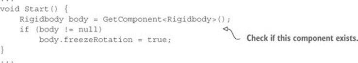
(A Rigidbody is an additional component an object can have. The physics simulation acts on Rigidbodies and manipulates objects they’re attached to.)
In case you’ve gotten lost on where to make the various changes and additions we’ve gone over, the next listing has the full finished script. Alternatively, download the example project.
Listing 2.7. The finished MouseLook script
using UnityEngine;
using System.Collections;
public class MouseLook : MonoBehaviour {
public enum RotationAxes {
MouseXAndY = 0,
MouseX = 1,
MouseY = 2
}
public RotationAxes axes = RotationAxes.MouseXAndY;
public float sensitivityHor = 9.0f;
public float sensitivityVert = 9.0f;
public float minimumVert = -45.0f;
public float maximumVert = 45.0f;
private float _rotationX = 0;
void Start() {
Rigidbody body = GetComponent<Rigidbody>();
if (body != null)
body.freezeRotation = true;
}
void Update() {
if (axes == RotationAxes.MouseX) {
transform.Rotate(0, Input.GetAxis("Mouse X") * sensitivityHor, 0);
}
else if (axes == RotationAxes.MouseY) {
_rotationX -= Input.GetAxis("Mouse Y") * sensitivityVert;
_rotationX = Mathf.Clamp(_rotationX, minimumVert, maximumVert);
float rotationY = transform.localEulerAngles.y;
transform.localEulerAngles = new Vector3(_rotationX, rotationY, 0);
}
else {
_rotationX -= Input.GetAxis("Mouse Y") * sensitivityVert;
_rotationX = Mathf.Clamp(_rotationX, minimumVert, maximumVert);
float delta = Input.GetAxis("Mouse X") * sensitivityHor;
float rotationY = transform.localEulerAngles.y + delta;
transform.localEulerAngles = new Vector3(_rotationX, rotationY, 0);
}
}
}
When you run the new script, you’re able to look around in all directions while moving the mouse. Great! But you’re still stuck in one place, looking around as if mounted on a turret. The next step is moving around the scene.
2.5. Keyboard input component: first-person controls
Looking around in response to mouse input is an important part of first-person controls, but you’re only halfway there. The player also needs to move in response to keyboard input. Let’s write a keyboard controls component to complement the mouse controls component; create a new C# script called FPSInput and attach that to the player (alongside the MouseLook script). For the moment set the MouseLook component to horizontal rotation only.
Tip
The keyboard and mouse controls explained here are split up into separate scripts. You don’t have to structure the code this way, and you could have everything bundled into a single “player controls” script, but a component system (such as the one in Unity) tends to be most flexible and thus most useful when you have functionality split into several smaller components.
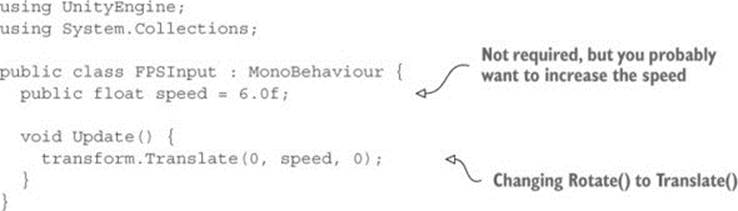
The code you wrote in the previous section affected rotation only, but now we’ll change the object’s position instead. As shown in listing 2.8, refer back to the rotation code from before we added mouse input; type that into FPSInput, but change Rotate() to Translate(). When you hit Play, the view slides up instead of spinning around. Try changing the parameter values to see how the movement changes (in particular, try swapping the first and second numbers); after experimenting with that for a bit, you can move on to adding keyboard input.
Listing 2.8. Spin code from the first listing, with a couple of minor changes
2.5.1. Responding to key presses
The code for moving according to key presses (shown in the following listing) is similar to the code for rotating according to the mouse. The GetAxis() method is used here as well, and in a very similar way. The following listing demonstrates how to use that command.
Listing 2.9. Positional movement responding to key presses
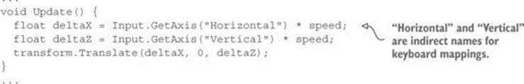
As before, the GetAxis() values are multiplied by speed in order to determine the amount of movement. Whereas before the requested axis was always “Mouse something,” now we pass in either Horizontal or Vertical. These names are abstractions for input settings in Unity; if you look in the Edit menu under Project Settings and then look under Input, you’ll find a list of abstract input names and the exact controls mapped to those names. Both the left/right arrow keys and the letters A/D are mapped to Horizontal, whereas both the up/down arrow keys and the letters W/S are mapped to Vertical.
Note that the movement values are applied to the X and Z coordinates. As you probably noticed while experimenting with the Translate() method, the X coordinate moves from side to side and the Z coordinate moves forward and backward.
Put in this new movement code and you should be able to move around by pressing either the arrow keys or WASD letter keys, the standard in most FPS games. The movement script is nearly complete, but we have a few more adjustments to go over.
2.5.2. Setting a rate of movement independent of the computer’s speed
It’s not obvious right now because you’ve only been running the code on one computer (yours), but if you ran it on different machines it’d run at different speeds. That’s because some computers can process code and graphics faster than others. Right now the player would move at different speeds on different computers because the movement code is tied to the computer’s speed. That is referred to as frame rate dependent, because the movement code is dependent on the frame rate of the game.
For example, imagine you run this demo on two different computers, one that gets 30 fps (frames per second) and one that gets 60 fps. That means Update() would be called twice as often on the second computer, and the same speed value of 6 would be applied every time. At 30 fps the rate of movement would be 180 units/second, and the movement at 60 fps would be 360 units/second. For most games, movement speed that varies like this would be bad news.
The solution is to adjust the movement code to make it frame rate independent. That means the speed of movement is not dependent on the frame rate of the game. The way to achieve this is by not applying the same speed value at every frame rate. Instead, scale the speed value higher or lower depending on how quickly the computer runs. This is achieved by multiplying the speed value by another value called deltaTime, as shown in the next listing.
Listing 2.10. Frame rate independent movement using deltaTime
...
void Update() {
float deltaX = Input.GetAxis("Horizontal") * speed;
float deltaZ = Input.GetAxis("Vertical") * speed;
transform.Translate(deltaX * Time.deltaTime, 0, deltaZ * Time.deltaTime);
}
...
That was a simple change. The Time class has a number of properties and methods useful for timing, and one of those properties is deltaTime. Because we know that delta means the amount of change, that means deltaTime is the amount of change in time. Specifically, deltaTime is the amount of time between frames. The time between frames varies at different frame rates (for example, 30 fps is a deltaTime of 1/30th of a second), so multiplying the speed value by deltaTime will scale the speed value on different computers.
Now the movement speed will be the same on all computers. But the movement script is still not quite done; when you move around the room you can pass through walls, so we need to adjust the code further to prevent that.
2.5.3. Moving the CharacterController for collision detection
Directly changing the object’s transform doesn’t apply collision detection, so the character will pass through walls. To apply collision detection, what we want to do instead is use CharacterController. CharacterController is a component that makes the object move more like a character in a game, including colliding with walls. Recall that back when we set up the player, we attached a CharacterController, so now we’ll use that component with the movement code in FPSInput (see the following listing).
Listing 2.11. Moving CharacterController instead of Transform
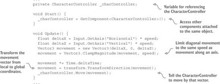
This code excerpt introduces several new concepts. The first concept to point out is the variable for referencing the CharacterController. This variable simply creates a local reference to the object (code object, that is—not to be confused with scene objects); multiple scripts can have references to this one CharacterController instance.
That variable starts out empty, so before you can use the reference you need to assign an object to it for it to refer to. This is where GetComponent() comes into play; that method returns other components attached to the same GameObject. Rather than pass a parameter inside the parentheses, you use the C# syntax of defining the type inside angle brackets, <>.
Once you have a reference to the CharacterController, you can call Move() on the controller. Pass in a vector to that method, similar to how the mouse rotation code used a vector for rotation values. Also similar to how rotation values were limited, use Vector3.ClampMagnitude() to limit the vector’s magnitude to the movement speed; the clamp is used because otherwise diagonal movement would have a greater magnitude than movement directly along an axis (picture the sides and hypotenuse of a right triangle).
But there’s one tricky aspect to the movement vector here, and it has to do with local versus global, as we discussed earlier for rotations. We’ll create the vector with a value to move, say, to the left. That’s the player’s left, though, which may be a completely different direction from theworld’s left. That is, we’re talking about left in local space, not global space. We need to pass a movement vector defined in global space to the Move() method, so we’re going to need to convert the local space vector into global space. Doing that conversion is extremely complex math, but fortunately for us Unity takes care of that math for us, and we simply need to call the method TransformDirection() in order to, well, transform the direction.
Definition
Transform used as a verb means to convert from one coordinate space to another (refer back to section 2.3.3 if you don’t remember what a coordinate space is). Don’t get confused with the other definitions of transform, including both the Transform component and the action of moving the object around the scene. It’s sort of an overloaded term, because all these meanings refer to the same underlying concept.
Test playing the movement code now. If you haven’t done so already, set the Mouse-Look component to both horizontal and vertical rotation. You can look around the scene fully and fly around the scene using keyboard controls. This is pretty great if you want the player to fly around the scene, but what if you want the player walking around on the ground?
2.5.4. Adjusting components for walking instead of flying
Now that collision detection is working, the script can have gravity and the player will stay down against the floor. Declare a gravity variable and then use that gravity value for the Y-axis, as shown in the next listing.
Listing 2.12. Adding gravity to the movement code
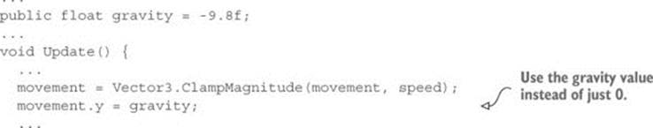
Now there’s a constant downward force on the player, but it’s not always pointed straight down, because the player object can tilt up and down with the mouse. Fortunately everything we need to fix that is already in place, so we just need to make some minor adjustments to how components are set up on the player. First set the Mouse-Look component on the player object to horizontal rotation only. Next add the MouseLook component to the camera object, and set that one to vertical rotation only. That’s right; you’re going to have two different objects responding to the mouse!
Because the player object now only rotates horizontally, there’s no longer any problem with the downward force of gravity being tilted. The camera object is parented to the player object (remember when we did that in the Hierarchy view?), so even though it rotates vertically independently from the player, the camera rotates horizontally along with the player.
Polishing the finished script
Use the RequireComponent() method to ensure that other components needed by the script are also attached. Sometimes other components are optional (that is, code that says “If this other component is also attached, then...”), but sometimes you want to make the other components mandatory. Add the method to the top of the script in order to enforce that dependency and give the required component as a parameter.
Similarly, if you add the method AddComponentMenu() to the top of your scripts, that script will be added to the component menu in Unity’s editor. Tell the command the name of the menu item you want to add, and then the script can be selected when you click Add Component at the bottom of the Inspector. Handy!
A script with both methods added to the top would look something like this:
using UnityEngine;
using System.Collections;
[RequireComponent(typeof(CharacterController))]
[AddComponentMenu("Control Script/FPS Input")]
public class FPSInput : MonoBehaviour {
...
Listing 2.13 shows the full finished script. Along with the small adjustments to how components are set up on the player, the player can walk around the room. Even with the gravity variable being applied, you can still use this script for flying movement by setting Gravity to 0 in the Inspector.
Listing 2.13. The finished FPSInput script
using UnityEngine;
using System.Collections;
[RequireComponent(typeof(CharacterController))]
[AddComponentMenu("Control Script/FPS Input")]
public class FPSInput : MonoBehaviour {
public float speed = 6.0f;
public float gravity = -9.8f;
private CharacterController _charController;
void Start() {
_charController = GetComponent<CharacterController>();
}
void Update() {
float deltaX = Input.GetAxis("Horizontal") * speed;
float deltaZ = Input.GetAxis("Vertical") * speed;
Vector3 movement = new Vector3(deltaX, 0, deltaZ);
movement = Vector3.ClampMagnitude(movement, speed);
movement.y = gravity;
movement *= Time.deltaTime;
movement = transform.TransformDirection(movement);
_charController.Move(movement);
}
}
Congratulations on building this 3D project! We covered a lot of ground in this chapter, and now you’re well-versed in how to code movement in Unity. As exciting as this first demo is, it’s still a long way from being a complete game. After all, the project plan described this as a basic FPS scene, and what’s a shooter if you can’t shoot? So give yourself a well-deserved pat on the back for this chapter’s project, and then get ready for the next step.
2.6. Summary
In this chapter you learned that
· 3D coordinate space is defined by X-, Y-, and Z-axes.
· Objects and lights in a room set the scene.
· The player in a first-person scene is essentially a camera.
· Movement code applies small transforms repeatedly in every frame.
· FPS controls consist of mouse rotation and keyboard movement.