Unity in Action: Multiplatform game development in C# with Unity 5 (2015)
Part 2. Getting comfortable
You’ve built your first game prototypes in Unity, so now you’re ready to stretch yourself by tackling some other game genres. At this point the rhythms of working within Unity should feel familiar: create a script with such and such function, drag this object to that slot in the Inspector, and so forth. You’re not tripping over details of the interface so much anymore, which means the remaining chapters don’t need to rehash the basics.
Let’s run through a succession of additional projects that will progressively teach you more and more about developing games in Unity.
Chapter 5. Building a Memory game using Unity’s new 2D functionality
This chapter covers
· Displaying 2D graphics in Unity
· Making objects clickable
· Loading new images programmatically
· Maintaining and displaying state using UI text
· Loading levels and restarting the game
Up to now we’ve been working with 3D graphics. But you can also work with 2D graphics in Unity, so in this chapter you’ll build a 2D game to learn about that. We’re going to develop the classic children’s game Memory: we’ll display a grid of card backs, reveal the card front when it’s clicked, and score matches. These mechanics cover the basics you need to know in order to develop 2D games in Unity.
Although Unity originated as a tool for 3D games, it’s used often for 2D games as well. Recent versions of Unity (starting with version 4.3, released near the end of 2013) have added the ability to display 2D graphics, but even before then 2D games were already being developed in Unity (especially mobile games that took advantage of Unity’s cross-platform nature). In prior versions of Unity, game developers required a third-party framework (such as 2D Toolkit from Unikron Software) to emulate 2D graphics within Unity’s 3D scenes. Eventually the core editor and game engine were modified to incorporate 2D graphics, and this chapter will teach you about that newer functionality.
The 2D workflow in Unity is more or less the same as the workflow to develop a 3D game: import art assets, drag them into a scene, and write scripts to attach to the objects. The primary kind of art asset in 2D graphics is called a sprite.
Definition
Sprites are 2D images displayed directly on the screen, as opposed to images displayed on the surface of 3D models (that is, textures).
You can import 2D images into Unity as sprites in much the same way you can import images as textures (see chapter 4). Technically these sprites will be objects in 3D space, but they’ll be flat surfaces all oriented along the Z-axis. Because they’ll all face the same direction, you can point the camera straight at the sprites and players will only be able to discern their movements along the X- and Y-axes (that is, two dimensions).
In chapter 2 we discussed the coordinate axes: having three dimensions adds a Z-axis perpendicular to the X- and Y-axes you were already familiar with. Two dimensions are just those X- and Y-axes (that’s what your teacher was talking about in math class!).
5.1. Setting everything up for 2D graphics
We’re going to create the classic game of Memory. For those unfamiliar with this game, a series of cards will be dealt out facedown. Every card will have a matching card located somewhere else, but the player can’t tell what the various cards are. The player can turn over two cards at a time, attempting to find matching cards; if the two cards chosen aren’t a match, they’ll flip back and then the player can guess again.
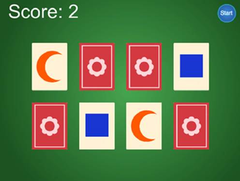
Figure 5.1 shows a mockup of the game we’re going to build; compare this to the roadmap diagram from chapter 2.
Figure 5.1. Mockup of what the Memory game will look like
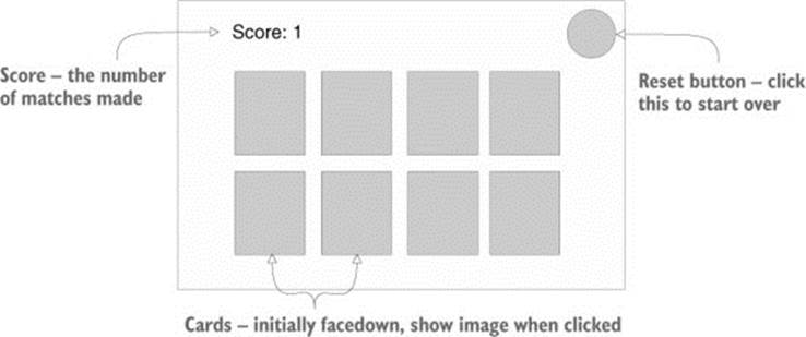
Note that the mockup this time depicts exactly what the player will see (whereas the mockup for a 3D scene depicted the space around the player and then where the camera went for the player to see through). Now that you know what we’ll be building, it’s time to get to work!
5.1.1. Preparing the project
The first step is to gather up and display graphics for our game. In much the same way as building the 3D demo previously, you want to start the new game by putting together the minimum set of graphics for the game to operate, and after that’s in place you can start programming the functionality.
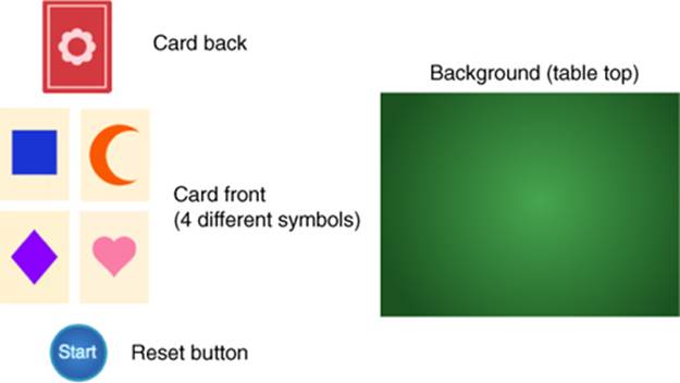
That means we’ll need to create everything depicted in figure 5.1: card backs for hidden cards, a series of card fronts for when they turn over, a score display in one corner, and a reset button in the opposite corner. We also need a background for the screen, so all together our art requirements sum up to figure 5.2.
Figure 5.2. Art assets required for the Memory game
Tip
As always, a finished version of the project, including all necessary art assets, can be downloaded from www.manning.com/hocking, this book’s website. You can copy the images from there to use in your own project.
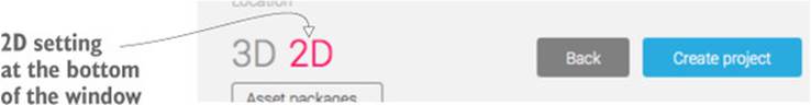
Gather together the needed images, and then create a new project in Unity. In the New Project window that comes up you’ll notice a couple of buttons at the bottom (shown in figure 5.3) that let you switch between 2D and 3D mode. In previous chapters we’ve worked with 3D graphics, and because that’s the default value we haven’t been concerned with this setting. In this chapter, though, you’ll want to switch to 2D mode when creating a new project.
Figure 5.3. Create new projects in either 2D or 3D mode with these buttons.
2D Editor mode and 2D Scene view
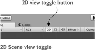
The 2D/3D setting for new projects adjusts two different settings within Unity’s editor, both of which you can adjust manually later if you wish. Those two settings are the 2D Editor mode and the 2D Scene view. The 2D Scene view controls how the scene is displayed within Unity; toggle the 2D button along the top of the Scene view.
You set 2D Editor mode by opening the Edit menu and selecting Editor from the Project Settings drop-down menu. Within those settings you’ll see the Default Behavior Mode setting with selections for either 3D or 2D.
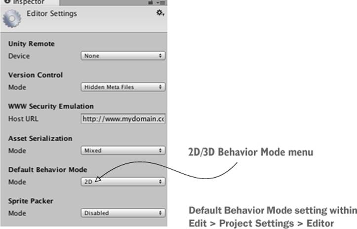
Setting the editor to 2D mode causes imported images to be set to Sprite; as you saw in chapter 4, normally images import as textures. 2D Editor mode also causes new scenes to lack the default 3D lighting setup; this lighting doesn’t harm 2D scenes, but it’s unnecessary. If you ever need to remove it manually, delete the directional light that comes with new scenes and turn off the skybox in the lighting window (click the tiny circle icon for a file picker and choose None from the list).
With the new project for this chapter created and set for 2D, we can start putting our images into the scene.
5.1.2. Displaying 2D images (aka sprites)
Drag all the image files into the Project view to import them; make sure the images are imported as sprites and not textures. (This is automatic if the editor is set to 2D. Select an asset to see its import settings in the Inspector.) Now drag the table_top sprite (our background image) up from the Project view into the empty scene, and then save the scene. As with mesh objects, in the Inspector there’s a Transform component for the sprite; type 0, 0, 5 to position the background image.
Tip
Another import setting to take note of is Pixels-To-Units. Because Unity was previously a 3D engine that recently had 2D graphics grafted in, one unit in Unity isn’t necessarily one pixel in the image. You could set the Pixels-To-Units setting to 1:1 but I recommend leaving it at the default of 100:1 (because the physics engine doesn’t work properly at 1:1, and the default is better for compatibility with others’ code).
Animated sprites
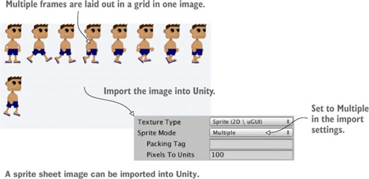
Although we’re going to use only still images for this project, 2D games commonly have animated sprites. Animated sprites are created by drawing each of the frames of the animation and then displaying the frames in sequence within Unity.
The multiple frames can be imported as separate images, but games usually have all the frames of animation laid out on a single image, called a sprite sheet. Sprite sheets can be generated automatically by Unity, or they can be created using a tool like Texture Packer (see appendix B). When importing a sprite sheet, set Sprite Mode to Multiple in the Sprite settings.
The sprite sheet will still appear in the Project view as a single asset, but if you click the arrow on the asset it’ll expand out and show all the individual sprites. Instead of dragging sprites into the scene one at a time, you can select a bunch to drag in together.
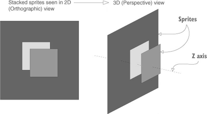
The 0 for X and Y position are straightforward (this sprite will fill the entire screen, so you want it at the center), but that 5 for Z position might seem odd. For 2D graphics, shouldn’t only X and Y matter? Well, X and Y are the only coordinates that matter for positioning the object on the 2D screen; Z coordinates still matter for stacking objects on top of each other, though. Lower Z values are closer to the camera, so sprites with lower Z values are displayed on top of other sprites (refer to figure 5.4). Accordingly, the background sprite should have the highest Z value. We’ll set our background to a positive Z position, and then give everything else a 0 or negative Z position.
Figure 5.4. How sprites stack along the Z-axis
Other sprites will be positioned with values up to two decimal places because of the Pixels-To-Units setting mentioned earlier. A ratio of 100:1 means that 100 pixels in the image are 1 unit in Unity; put another way, 1 pixel is .01 units. But before we put any more sprites into the scene, let’s set up the camera for this game.
Creating atlases using Sprite Packer
As mentioned in the sidebar “Animated Sprites,” you can have multiple sprites laid out in a single image. The image is usually called a sprite sheet when multiple frames of a single 2D animation are combined into one, but the more general term for multiple images combined into one is anatlas.
Sprite sheets are useful in order to keep frames of animation together, but sprite atlases are also often used for still images. That’s because atlases can optimize the performance of sprites in two ways: 1) by reducing the amount of wasted space in images by packing them tightly, and 2) by reducing the draw calls of the video card (every new image that’s loaded causes a bit more work for the video card).
Sprite atlases can be created using external tools (switch to Multiple in the Sprite settings) and that approach certainly will work. But Unity includes a Sprite Packer that will pack together multiple sprites automatically. To use this feature, enable Sprite Packer in Editor settings (found under Edit > Project Settings). Now write a name in Packing Tag option when looking at the Import settings of a sprite image; Unity will pack together sprites with the same packing tag into one atlas. For more information, look at Unity’s documentation:
http://docs.unity3d.com/Manual/SpritePacker.html
5.1.3. Switching the camera to 2D mode
Now let’s adjust settings on the main camera in the scene. You might think that because the Scene view is set to 2D, what you see in Unity is what you’ll see in the game. Somewhat non-intuitively, though, that isn’t the case.
Warning
Whether or not the Scene view is set to 2D has nothing to do with the camera view in the running game.
It turns out that regardless of whether the Scene view is set to 2D mode, the camera in the game is set independently. This can be handy in many situations so that you can toggle the Scene view back to 3D in order to work on certain effects within the scene. This disconnect does mean that what you see in Unity isn’t necessarily what you see in the game, and it can be easy for beginners to forget this.
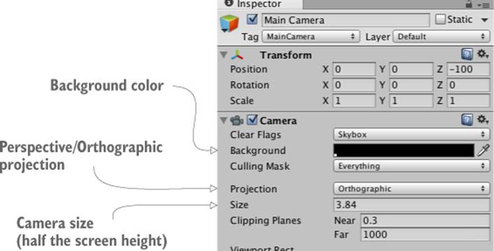
The most important camera setting to adjust is Projection. The camera projection is probably already correct because you created the new project in 2D mode, but this is still important to know about and worth double-checking. Select the camera in Hierarchy to show its settings in the Inspector, and then look for the Projection setting (see figure 5.5). For 3D graphics the setting should be Perspective, but for 2D graphics the camera projection should be Orthographic.
Figure 5.5. Camera settings to adjust for 2D graphics
Definition
Orthographic is the term for a flat camera view that has no perspective apparent. This is the opposite of a Perspective camera, where closer objects appear larger and lines recede into the distance.
Although the Projection mode is the most important camera setting for 2D graphics, there are a few other settings for us to adjust as well. Next we’ll look at Size; that setting is under Projection. The camera’s orthographic size determines the size of the camera view from the center of the screen up to the top of the screen. In other words, set Size to half the pixel dimensions of the screen you want. If you later set the resolution of the deployed game to the same pixel dimensions, you’ll get pixel-perfect graphics.
Definition
Pixel-perfect means one pixel on the screen corresponds to one pixel in the image (otherwise, the video card will make the images subtly blurry while scaling up to fit the screen).
For example, let’s say you want a pixel-perfect 1024x768 screen. That means the camera height should be 384 pixels. Divide that by 100 (because of the pixels-to-units scale) and you get 3.84 for the camera size. Again, that math is SCREEN_SIZE / 2 / 100f (f as in float, rather than anint value). Given that the background image is 1024x768 (select the asset to check its dimensions), then clearly this value of 3.84 is what we want for our camera.
The two remaining adjustments to make in the Inspector are the camera’s background color and Z position. As mentioned previously for sprites, higher Z positions are further away into the scene. Thus the camera should have a pretty low Z position; set the position of the camera to 0, 0, -100. The camera’s background color should probably be black; the default color is blue, and that’ll look odd displayed along the sides if the screen is wider than the background image (which is likely). Click the color swatch next to Background and set the color picker to black.
Now save the scene as Scene and hit Play; you’ll see the Game view filled with our tabletop sprite. As you saw, getting to this point wasn’t completely obvious (again, that’s because Unity was a 3D game engine that recently had 2D graphics grafted in). But the tabletop is completely bare, so our next step is to put a card on the table.
5.2. Building a card object and making it react to clicks
Now that the images are all imported and ready to use, let’s build the card objects that form the core of this game. In Memory, all the cards are initially face down, and they’re only face up temporarily when you choose a pair of cards to turn over. To implement this functionality, we’re going to create objects that consist of multiple sprites stacked on top of one another. Then we’ll write code that makes the cards reveal themselves when clicked with the mouse.
5.2.1. Building the object out of sprites
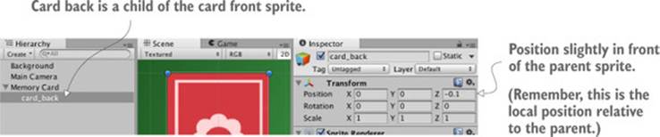
Drag one of the card images into the scene. Use one of the card fronts, because you’ll add a card back on top to hide the image. Technically the position right now doesn’t matter, but eventually it will matter so you may as well position the card at -3, 1, 0. Now drag the card_back sprite into the scene. Make this new sprite a child of the previous card sprite (remember, in the Hierarchy drag the child object onto the parent object) and then set its position to 0, 0, -.1 (Keep in mind that this position is relative to the parent, so this means “Put it at the same X Y but move it closer on Z.”)
Tip
Instead of the Move, Rotate, and Scale tools that we used in 3D, in 2D mode we use a single manipulation tool called the Rect Tool. In 2D mode this tool is selected automatically, or you can click the rightmost navigation button in the top-left corner of Unity. With this tool active, click and drag objects to do all three operations (move/rotate/scale) in two dimensions.
With the card back in place as depicted in figure 5.6, the graphics are in place for a reactive card that can be revealed.
Figure 5.6. Hierarchy linking and position for the card back sprite
5.2.2. Mouse input code
In order to respond when the player clicks on them, the card sprites need to have a collider component. New sprites don’t have a collider by default, so they can’t be clicked on. We’re going to attach a collider to the root card object, but not to the card back, so that only the card front and not the card back will receive mouse clicks. To do this, select the root card object in Hierarchy (don’t click the card in the scene, because the card back is on top and you’ll select that part instead) and then click the Add Component button in the Inspector. Select Physics 2D (not Physics, because that system is for 3D physics and this is a 2D game), and then choose a box collider.
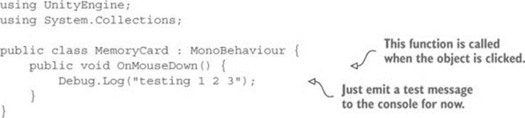
Besides a collider, the card needs a script in order to be reactive to the player clicking on it, so let’s write some code. Create a new script called MemoryCard.cs and attach this script to the root card object (again, not the card back). The following listing shows the code that makes the card emit debug messages when clicked.
Listing 5.1. Emitting debug messages when clicked
Tip
If you’re not in this habit yet, organizing your assets into separate folders is probably a good idea; create folders for scripts and drag files within the Project view. Just be careful to avoid the special folder names Unity responds to: Resources, Plugins, Editor, and Gizmos. Later in the book we’ll go over what some of these special folders do, but for now avoid naming any folders with those words.
Nice, we can click on the card now! Just like Update(), OnMouseDown() is another function provided by MonoBehaviour, this time responding when the object is clicked on. Play the game and watch messages appear in the console. But this only prints to the console for testing; we want the card to be revealed.
5.2.3. Revealing the card on click
Rewrite the code to match what’s shown in the next listing (the code won’t run quite yet but don’t worry).
Listing 5.2. Script that hides the back when the card is clicked
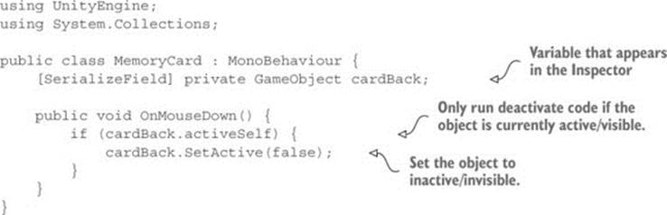
There are two key additions to the script: a reference to an object in the scene, and the SetActive() method that deactivates that object. The first part, the reference to an object in the scene, is similar to what we’ve done in previous chapters: mark the variable as serialized, and then drag the object from Hierarchy over to the variable in the Inspector. With the object reference set, the code will now affect the object in the scene.
The second key addition to the code is the SetActive command. That command will deactivate any GameObject, making that object invisible. If we now drag card_back in the scene to this script’s variable in the Inspector, when you play the game the card back disappears when you click the card. Hiding the card back will reveal the card front; we’ve accomplished yet another important task for the Memory game! But this is still only one card, so now let’s create a bunch of cards.
5.3. Displaying the various card images
We’ve programmed a card object that initially shows the card back but reveals itself when clicked. That was a single card, but the game needs a whole grid of cards, with different images on most cards. We’ll implement the grid of cards using a couple concepts seen in previous chapters, along with some new concepts you haven’t seen before. Chapter 3 included both the notions of 1) using an invisible SceneController component and 2) instantiating clones of an object. This time the SceneController will apply different images to different cards.
5.3.1. Loading images programmatically
There are four card images in the game we’re creating. All eight cards on the table (two for each symbol) will be created by cloning the same original, so initially all cards will have the same symbol. We’ll have to change the image on the card in the script, loading different images programmatically.
To examine how images can be assigned programmatically, let’s write some simple test code (that will be replaced later) to demonstrate the technique. First add the code from the following listing to the MemoryCard script.
Listing 5.3. Test code to demonstrate changing the sprite image
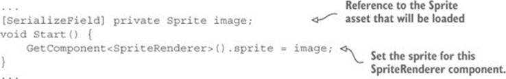
After you save this script, the new image variable will appear in the Inspector because it has been set as serialized. Drag a sprite up from the Project view (pick one of the card images, and not the same as the image already in the scene) and drop it on the Image slot. Now run the scene, and you’ll see the new image on the card.
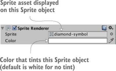
The key to understanding this code is to know about the SpriteRenderer component. You’ll notice in figure 5.7 that the card back object has just two components, the standard Transform component on all objects in the scene, and a new component called Sprite Renderer. This component makes it a sprite object and determines which sprite asset will be displayed. Note that the first property in the component is called Sprite and links to one of the sprites in the Project view; the property can be manipulated in code, and that’s precisely what this script does.
Figure 5.7. A sprite object in the scene has the SpriteRenderer component attached to it.
As it did with CharacterController and custom scripts in previous chapters, the GetComponent() method returns other components on the same object, so we use it to reference the SpriteRenderer object. The sprite property of SpriteRenderer can be set to any sprite asset, so this code sets that property to the Sprite variable declared at the top (which we filled with a sprite asset in the editor).
Well, that wasn’t too hard! But it’s only a single image; we have four different images to use, so now delete the new code from listing 5.3 (it was only a quick demonstration of how the technique works) to prepare for the next section.
5.3.2. Setting the image from an invisible SceneController
Recall in chapter 3 how we created an invisible object in the scene to control spawning objects. We’re going to take that approach here as well, using an invisible object to control more abstract features that aren’t tied to any specific object in the scene. First create an empty GameObject (remember, select menu GameObject > Create Empty). Then create a new script SceneController.cs in the Project view, and drag this script asset onto the controller GameObject. Before writing code in the new script, first add the contents of the next listing to the MemoryCard script instead of what you saw in listing 5.3.
Listing 5.4. New public methods in MemoryCard.cs
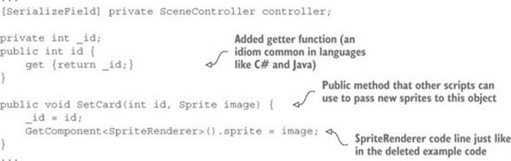
The primary change from previous listings is that we’re now setting the sprite image in SetCard() instead of Start(). Because that’s a public method that takes a sprite as a parameter, you can call this function from other scripts and set the image on this object. Note that SetCard() also takes an ID number as a parameter, and the code stores that number. Although we don’t need the ID quite yet, soon we’ll write code that compares cards for matches, and that comparison will rely on the IDs of the cards.
Note
Depending on what programming languages you’ve used in the past, you may not be familiar with the concept of “getters” and “setters.” Long story short, those are functions that run when you attempt to access the property associated with them (for example, retrieving the value ofcard.id). There are multiple reasons to use getters and setters, but in this case the id property is read-only because there’s only a function to get the value and not set it.
Lastly, note that the code has a variable for the controller; even as SceneController starts cloning card objects to fill the scene, the card objects also need a reference back to the controller to call its public methods. As usual, when the code references objects in the scene, drag the controller object in Unity’s editor to the variable slot in the Inspector. Do this once for this single card and all of the copies to come later will have the reference as well.
With that additional code now in MemoryCard, write the code from the next listing in SceneController.
Listing 5.5. First pass at SceneController for the Memory game
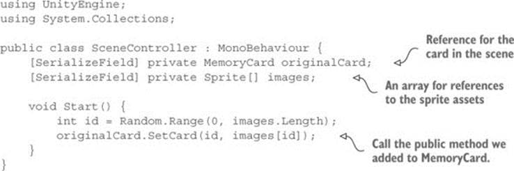
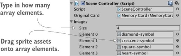
For now this is a short snippet to demonstrate the concept of manipulating cards from SceneController. Most of this should already be familiar to you (for example, in Unity’s editor, drag the card object to the variable slot in the Inspector), but the array of images is new. As shown in figure 5.8, in the Inspector you can set the number of elements. Type in 4 for the array length, and then drag the sprites for card images onto the array slots. Now these sprites can be accessed in the array, like any other object reference.
Figure 5.8. The filled-in array of sprites
Incidentally, we used the Random.Range() method in chapter 3, so hopefully you recall that. The exact boundary values didn’t matter there, but this time it’s important to note that the minimum value is inclusive and may be returned, whereas the return value is always below the maximum.
Hit Play to run this new code. You’ll see different images being applied to the revealed card each time you run the scene. The next step is to create a whole grid of cards, instead of just one.
5.3.3. Instantiating a grid of cards
SceneController already has a reference to the card object, so now you’ll use the Instantiate() method (see the next listing) to clone the object numerous times, like spawning objects in chapter 3.
Listing 5.6. Cloning the card eight times and positioning in a grid
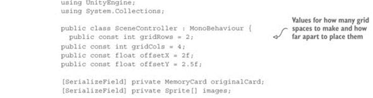
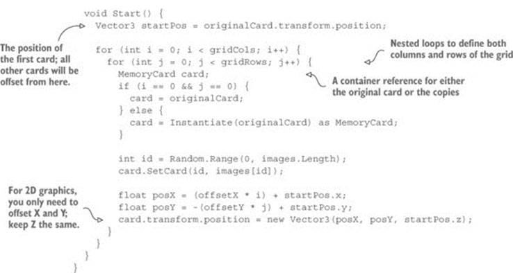
Although this script is much longer than the previous listing, there’s not a lot to explain because most of the additions are straightforward variable declarations and math. The oddest bit of this code is probably the if/else statement that begins if (i == 0 && j == 0). What that conditional does is either choose the original card object for the first grid slot or clone the card object for all other grid slots. Because the original card already exists in the scene, if you copied the card at every iteration of the loop you’d end up with one too many cards in the scene. The cards are then positioned by offsetting them according to the number of iterations through the loop.
Tip
Just as when moving 3D objects, 2D objects can be moved by manipulating transform.position to different points on the screen, and this position could be incremented repeatedly in Update(). But as you saw when moving the first-person player, collision detection isn’t applied when adjusting transform.position directly. To move 2D objects with collision detection, you’ll probably want to adjust rigidbody2D.velocity after assigning Physics2D components.
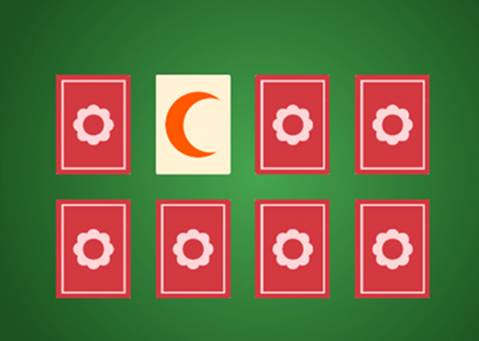
Run the code now and a grid of eight cards will be created (as depicted in figure 5.9). The last step in preparing the grid of cards is to organize them into pairs, instead of them being random.
Figure 5.9. The grid of eight cards that are revealed when you click on them
5.3.4. Shuffling the cards
Instead of making every card random, we’ll define an array of all the card IDs (numbers 0 through 3 twice, for a pair of each card) and then shuffle that array. We’ll then use this array of card IDs when setting cards, rather than making each one random. The following listing shows the code.
Listing 5.7. Placing cards from a shuffled list
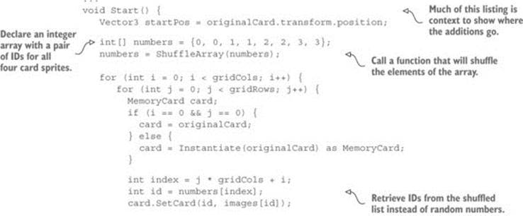
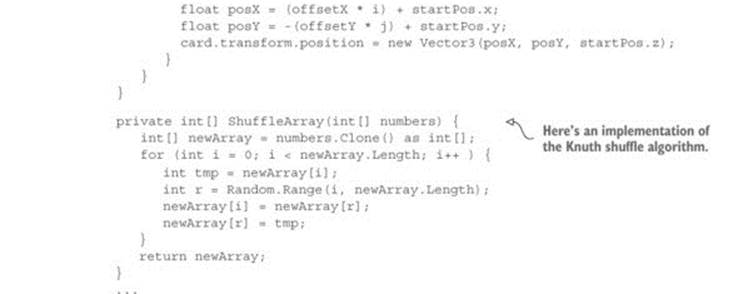
Now when you hit Play the grid of cards will be a shuffled assortment that reveals exactly two of each card image. The array of cards was run through the Knuth (also known as Fisher-Yates) shuffle algorithm, a simple yet effective way of shuffling the elements of an array. This algorithm loops through the array and swaps every element of the array with a randomly chosen other array position.
You can click on all the cards to reveal them, but the game of Memory is supposed to proceed in pairs; a bit more code is needed.
5.4. Making and scoring matches
The last step in making a fully functional Memory game is checking for matches. Although we now have a grid of cards that are revealed when clicked, the various cards don’t affect each other in any way. In the game of Memory, every time a pair of cards is revealed we should check to see if the revealed cards match.
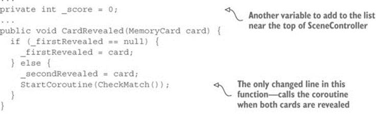
This abstract logic—checking for matches and responding appropriately—requires that cards notify SceneController when they’ve been clicked. That requires the additions to SceneController.cs shown in the next listing.
Listing 5.8. SceneController, which must keep track of revealed cards
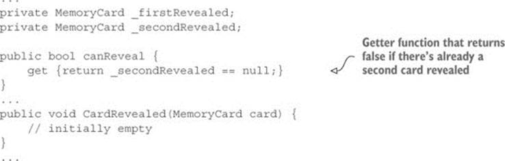
The CardRevealed() method will be filled in momentarily; we needed the empty scaffolding for now to refer to in MemoryCard.cs without any compiler errors. Note that there is a read-only getter again, this time used to determine whether another card can be revealed; the player can only reveal another card when there aren’t already two cards revealed.
We also need to modify MemoryCard.cs to call the (currently empty) method in order to inform SceneController when a card is clicked. Modify the code in MemoryCard.cs according to the following listing.
Listing 5.9. MemoryCard.cs modifications for revealing cards
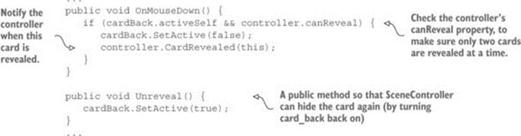
If you were to put a debug statement inside CardRevealed() in order to test the communication between objects, you’d see the test message appear whenever you click a card. Let’s first handle one revealed card.
5.4.1. Storing and comparing revealed cards
The card object was passed into CardRevealed(), so let’s start keeping track of the revealed cards. Write the code from the following listing.
Listing 5.10. Keeping track of revealed cards in SceneController
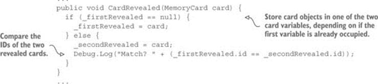
The listing stores the revealed cards in one of the two card variables, depending on whether the first variable is already occupied. If the first variable is empty, then fill it; if it’s already occupied, fill the second variable and check the card IDs for a match. The debug statement prints eithertrue or false in the console.
At the moment the code doesn’t respond to matches—it only checks for them. Now let’s program the response.
5.4.2. Hiding mismatched cards
We’ll use coroutines again because the reaction to mismatched cards should pause to allow the player to see the cards. Refer back to chapter 3 for a full explanation of coroutines; long story short, using a coroutine will allow us to pause when checking for a match. The next listing shows more code for you to add to SceneController.
Listing 5.11. SceneController, which either scores matches or hides missed matches
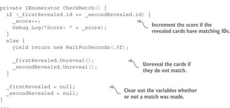
First add a _score value to track; then launch a coroutine to CheckMatch() when a second card is revealed. In that coroutine there are two code paths, depending on whether the cards match. If they do match, the coroutine doesn’t pause; the yield command gets skipped over. But if the cards don’t match, the coroutine pauses for half a second before calling Unreveal() on both cards, hiding them again. Finally, whether or not a match was made, the variables for storing cards are both nulled out, paving the way for revealing more cards.
When you play the game, mismatched cards will display briefly before hiding again. There are debug messages when you score matches, but we want the score displayed as a label on the screen.
5.4.3. Text display for the score
Displaying information to the player is half of the reason for a UI in a game (the other half is receiving input from the player; UI buttons are discussed in the next section).
Definition
UI stand for user interface. Another closely related term is GUI (graphical user interface), which refers to the visual part of the interface, such as text and buttons, and which is what a lot of people mean when they say UI.
Unity has multiple ways to create text displays. One way is to create a 3D text object in the scene. This is a special mesh component, so first create an empty object to attach this component to. From the GameObject menu, choose Create Empty. Then click the Add Component button and choose Mesh > Text Mesh.
Note
That name, 3D text, might sound incompatible with a 2D game, but don’t forget that this is technically a 3D scene that looks flat because it’s being seen through an orthographic camera. That means we can put 3D objects into the 2D game if we want—they’re just displayed in a flat perspective.
Position this object at -4.75, 3.65, -10; that’s 475 pixels to the left and 365 pixels up, putting it in the top-left corner, and nearer to the camera so that it’ll appear on top of other game objects. In the Inspector, look for the Font setting toward the bottom; click the little circle button to bring up a file selector, and then pick the Arial font that’s available. Enter Score: as the Text setting. Correct positioning also requires Upper Left for the Anchor setting (this controls how letters expand out as they’re typed), so change this if needed. By default the text appears blurry, but that’s easily fixed by adjusting the settings shown in figure 5.10.
Figure 5.10. Inspector settings for a text object to make the text sharp and clear
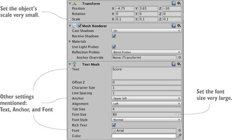
If we imported a new TrueType font into the project we could use that instead, but for our purposes the default font is fine. Oddly enough, a bit of size adjustment is needed to make the default text sharp and clear. First set the TextMesh component’s Font Size setting to a very large value (I used 80). Now scale the object down to be very small (like .1, .1, 1). Increasing Font Size added a lot of pixels to the text displayed, and scaling the object compressed those pixels into a smaller space.
Manipulating this text object requires just a few adjustments in the scoring code (see the next listing).
Listing 5.12. Displaying the score on a text object
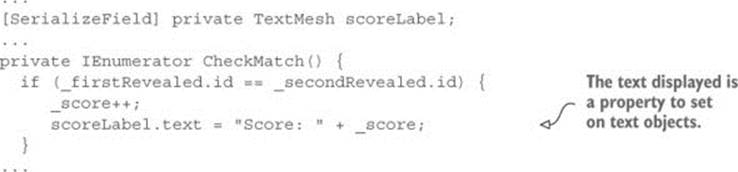
As you can see, text is a property of the object that you can set to a new string. Drag the text in the scene to the variable you just added to SceneController, and then hit Play. Now you should see the score displayed while you play the game and make matches. Huzzah, the game works!
5.5. Restart button
At this point the Memory game is fully functional. You can play the game, and all the essential features are in place. But this playable core is still lacking the overarching functionality that players expect or need in a finished game. For example, right now you can play the game only once; you need to quit and restart in order to play again. Let’s add a control to the screen so that players can start the game over without having to quit.
This functionality breaks down into two tasks: create a UI button, and reset the game when that button is clicked. Figure 5.11 shows what the game will look like with the restart button.
Figure 5.11. Complete Memory game screen, including the Start button
Neither task is specific to 2D games, by the way; all games need UI buttons, and all games need the ability to reset. We’ll go over both topics to round out this chapter.
5.5.1. Programming a UIButton component using SendMessage
First place the button sprite in the scene; drag it up from the Project view. Give it a position like 4.5, 3.25, -10; that will place the button in the top-right corner (that’s 450 pixels to the right and 325 pixels up) and move it nearer to the camera so that it’ll appear on top of other game objects. Because we want to be able to click on this object, give it a collider (just as with the card object, select Add Component > Physics 2D > Box Collider).
Note
As alluded to in the previous section, Unity provides multiple ways to create UI displays, including an advanced UI system introduced in the most recent versions of Unity. For now we’ll build the single button out of standard display objects. The next chapter will teach you about the advanced UI functionality; the UI for both 2D and 3D games is ideally built with that system.
Now create a new script called UIButton.cs and assign that script (shown in the following listing) to the button object.
Listing 5.13. Code to make a generic and reusable UI button
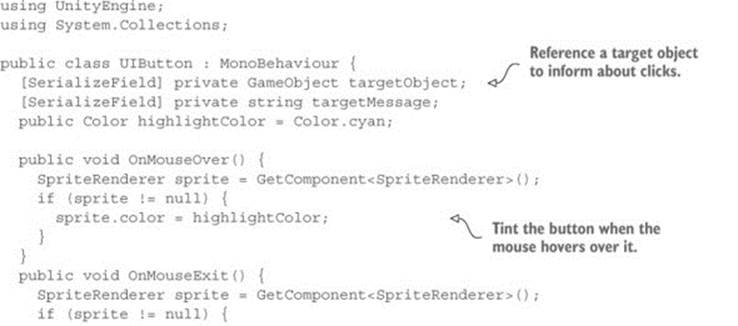
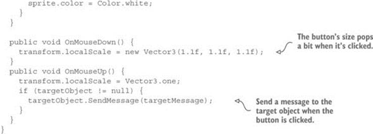
The majority of this code happens inside a series of OnMouseSomething functions; like Start() and Update(), these are a series of functions automatically available to all script components in Unity. MouseDown was mentioned back in section 5.2.2, but all these functions respond to mouse interactions if the object has a collider; MouseOver and MouseExit are a pair of events used for hovering the mouse cursor over an object: MouseOver is the moment when the mouse cursor first moves over an object, and MouseExit is the moment when the mouse cursor moves away. Similarly, MouseDown and MouseUp are a pair of events for clicking the mouse. MouseDown is the moment when the mouse button is physically pressed, and MouseUp is the moment when the mouse button is released.
You can see that this code tints the sprite when the mouse hovers over it and scales the sprite when it’s clicked on. In both cases you can see that the change (in color or scale) happens when the mouse interaction begins, and then the property returns to default (either white or scale 1) when the mouse interaction ends. For scaling, the code uses the standard transform component that all GameObjects have. For tint, though, the code uses the SpriteRenderer component that sprite objects have; the sprite is set to a color that’s defined in Unity’s editor through a public variable.
In addition to returning the scale to 1, SendMessage() is called when the mouse is released. SendMessage() calls the function of the given name in all components of that GameObject. Here the target object for the message, as well as the message to send, are both defined by serialized variables. This way, the same UIButton component can be used for all sorts of buttons, with the target of different buttons set to different objects in the Inspector.
Normally when doing object-oriented programming in a strongly typed language like C#, you need to know the type of a target object in order to communicate with that object (for example, to call a public method of the object, like calling target-Object.SendMessage() itself). But scripts for UI elements may have lots of different types of targets, so Unity provides the SendMessage() method to communicate specific messages with a target object even if you don’t know exactly what type of object it is.
Warning
Using SendMessage() is less efficient for the CPU than calling public methods on known types (that is, using object.SendMessage("Method") versus component.Method()) so only use SendMessage() when it’s a big win in terms of making the code simpler to understand and work with. As a general rule of thumb, that will only be the case if there could be lots of different types of objects receiving the message; in situations like that, the inflexibility of inheritance or even interfaces will hinder the game development process and discourage experimentation.
With this code written, wire up the public variables in the button’s Inspector. The highlight color can be set to whatever you’d like (although the default cyan looks pretty good on a blue button). Meanwhile, put the SceneController object in the target object slot, and then type Restart as the message.
If you play the game now, there’s a Reset button in the top-right corner that changes color in response to the mouse, and it makes a slight visual “pop” when clicked on. But an error message was emitted when you clicked the button; in the console you’ll see an error about there not being a receiver for the Restart message. That’s because we haven’t written a Restart() method in SceneController, so let’s add that next.
5.5.2. Calling LoadLevel from SceneController
The SendMessage() from the button attempts to call Restart() in the Scene-Controller, so let’s add that (see the next listing).
Listing 5.14. SceneController code that reloads the level
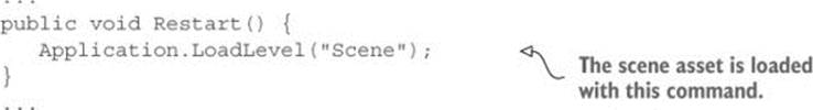
You can see the one thing Restart() does is call Application.LoadLevel(). That command loads a saved scene asset (that is, the file created when you click Save Scene in Unity). Pass the method the name of the scene you want to load; in my case the scene was saved with the nameScene, but if you used a different name, pass that to the method instead.
Hit Play to see what happens. Reveal a few cards and make a few matches; if you then click the Reset button, the game starts over, with all cards hidden and a score of 0. Great, just what we wanted!
As the name LoadLevel() implies, this method can load different levels. But what exactly happens when a level loads, and why does this reset the game? What happens is that everything from the current level (all objects in the scene, and thus all scripts attached to those objects) is flushed from memory, and then everything from the new scene is loaded. Because the “new” scene in this case is the saved asset of the current scene, everything is flushed from memory and then reloaded from scratch.
Tip
You can mark specific objects to exclude from the default memory flush when a level is loaded. Unity provides the DontDestroyOnLoad() method to keep an object around in multiple scenes; we’ll use this method on parts of the code architecture in later chapters.
Another game successfully completed! Well, “completed” is a relative term; you could always implement more features, but everything from the initial plan is done. Many of the concepts from this 2D game apply to 3D games as well, especially the checking of game state and loading levels. Time to switch gears yet again and move away from this Memory game and on to new projects.
5.6. Summary
In this chapter you’ve learned that
· Displaying 2D graphics in Unity uses an orthographic camera.
· For pixel-perfect graphics, the camera size should be half the screen height.
· Clicking on sprites requires that you first assign 2D colliders to them.
· New images for the sprites can be loaded programmatically.
· UI text can be made using 3D text objects.
· Loading levels resets the scene.