Blender Cycles: Materials and Textures Cookbook, Third Edition (2015)
Chapter 9. Special Materials
In this chapter, we will cover the following recipes:
· Using Cycles volume materials
· Creating a cloud volumetric material
· Creating a "fire and smoke" shader
· Creating a shadeless material in Cycles
· Creating a fake immersion effect material
· Creating a fake volume light material
Introduction
In this final chapter, we are going to see some special materials, that is, materials that can be used for special effects or for situations where very realistic results are not required, for example, creation of volumetric effects (fire, smoke, mist, volumetric light, and so on) and special materials to obtain peculiar results (shadeless images, alpha backgrounds, and so on).
Using Cycles volume materials
In all the recipes we have seen so far, Cycles used the Surface input socket and (very rarely) the Displacement input socket for the bump effects of the Material Output node to make the renderings. Assigning colors or textures to the surface of an object clearly means that interaction between a ray of light and an object happens only at the surface level of the object, and until this surface doesn't show what should be inside, that's OK. The surface attribute is enough for a realistic rendering.
Things get more complex when there is a need to show what's inside an object, for example, water inside a glass container, smoke and clouds in a thick atmosphere, and so on.
Usually, these are effects that require the use of the volume attribute more than the surface attribute to be effectively rendered.
So, in the first recipes of this chapter, we are going to see the use of the Volume input socket of the Material Output node. Rather than covering a specific material, this recipe is more of a "tour" to show the possibilities related to the Volume shader assigned to a mesh object. Have a look at the following screenshot:
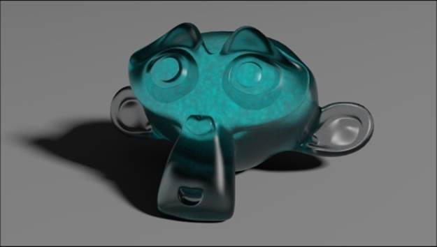
A glass Suzanne containing some kind of liquid
Getting ready
Start Blender and open the 9931OS_09_start.blend file, with the usual Suzanne object leaning on a Plane, a mesh-light Emitter, and the Camera.
1. Go to the Render window, and under the Sampling subpanel, set Samples for Preview to 50 and for Render to 100. Switch Pattern from Sobol to Correlated Multy-Jitter.
2. Still in the Render window, go to the Volume Sampling subpanel, and under the Heterogeneous item, set the Step Size value to 0.25. The default value is 0.10. Increasing this will make the rendering of volumes less accurate but faster, and lowering it will result in the opposite.
How to do it...
First, let's see the Volume applied to our usual Suzanne mesh primitive by performing the following steps:
1. Move the mouse to the Camera view and press Shift + Z to switch the Viewport Shading mode to Rendered.
2. Make sure that you have the Suzanne_unwrapped object selected, and click on the New button in the Node Editor toolbar, or in the Material window under the main Properties panel.
3. In the Node Editor window, press Ctrl and click and drag a line onto the link connecting the Diffuse BSDF shader to the Material Output node to cut it away. Because nothing is connected to the Material Output node sockets, in the Camera view, theSuzanne object turns pitch black as shown in the following screenshot:
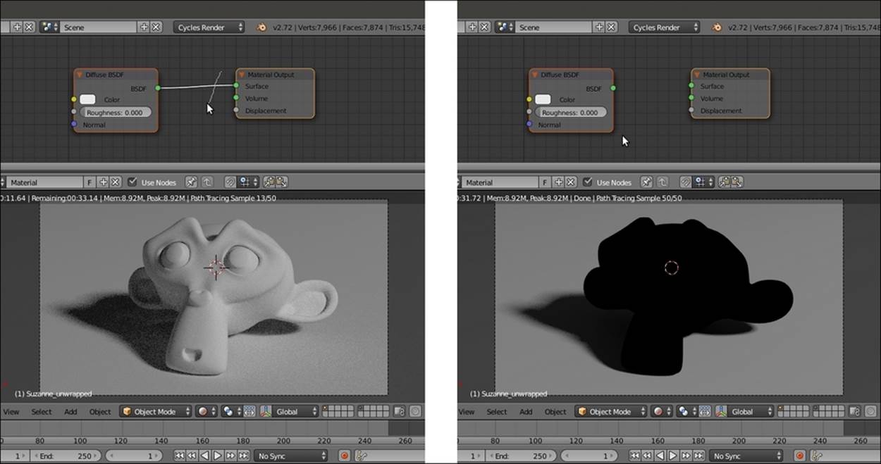
The Diffuse shader connected and disconnected from the Material Output node
4. Select and delete the Diffuse BSDF shader node. Still in the Node Editor window, add a Volume Scatter node (press Shift + A and navigate to Shader | Volume Scatter) and connect its output to the Volume input socket of the Material Output node.
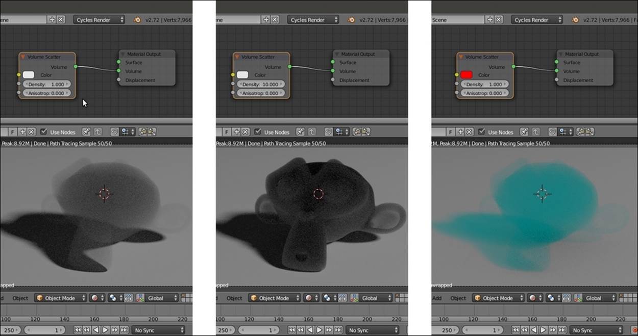
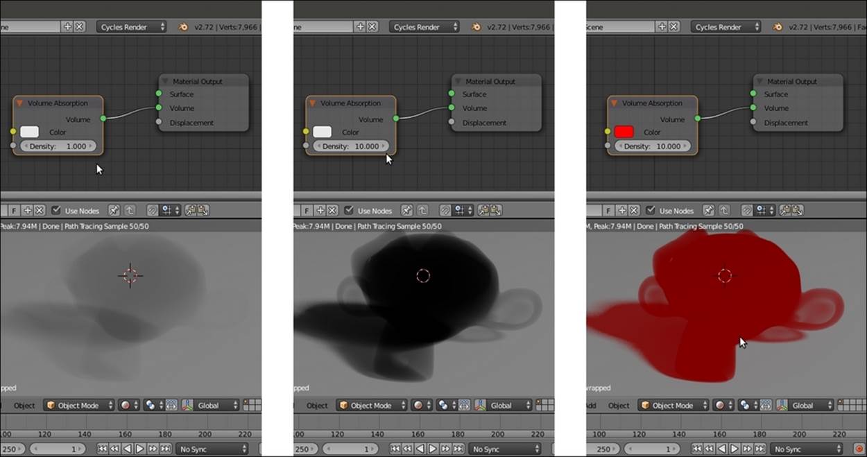
Different effects of the Volume Scatter node obtained by changing density and color
5. Try to increase the Density value to 10.000, either in the node interface in the Node Editor window, or in the slot under the Volume subpanel in the main Properties panel. Suzanne's volume looks more solid, as shown in the middle of the preceding screenshot.
6. Change the Density value back to the default 1.000 and change the Color values of the Volume Scatter node for R to 1.000, G to 0.000, and B to 0.000 (a red color). The Suzanne object now appears as complementary colored smoke (on the right side of the preceding screenshot) because light is scattered (note that the shadow on the Plane gets the same color).
7. Add a Glass BSDF shader (press Shift + A and navigate to Shader | Glass BSDF) and connect its output to the Surface input socket of the Material Output node. Set the IOR value to 1.440 and the Roughness value to 0.100.
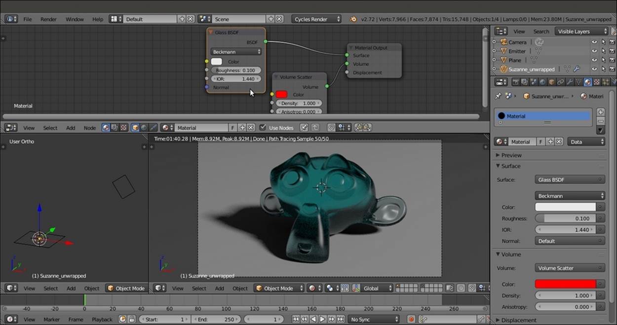
Adding a glassy envelope to the bluish, scattered glassy volume
8. Now you have to temporarily remove the connection of the Glass BSDF shader node to the Surface input socket of the Material Output node, take back the RGB value and set it to 0.800 for the Color of the Volume Scatter node.
9. Add a Texture Coordinate node (press Shift + A and navigate to Input | Texture Coordinate), a Voronoi Texture node (press Shift + A and navigate to Texture | Voronoi Texture), and a Math node (press Shift + A and navigate to Converter | Math).
10. Connect the Object output of the Texture Coordinate node to the Vector input socket of the Voronoi Texture node, and the Fac output of this node to the first Value input socket of the Math node. Set the second Value to 10.000, set Operation to Multiply, and connect its output to the Density input socket of the Volume Scatter node as shown in the following screenshot:
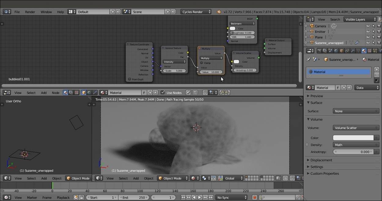
The Density value of the Volume Scatter node driven by a Voronoi texture output
11. Add a ColorRamp node (press Shift + A and go to | Converter | ColorRamp) and paste it between the Voronoi Texture and the Math nodes. Move the black color stop to position 0.195 and the white color stop to position 0.100 as shown in the following screenshot:
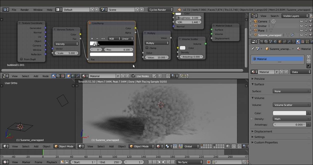
Enhancing the contrast of the texture output
12. Set the Voronoi Texture node's Scale value to 11.500, and reconnect the Glass BSDF shader node output to the Surface input socket of the Material Output node. Change the Color values of the Volume Scatter node for R to 1.000, G to 0.000, and B to0.000 as shown in the following screenshot:
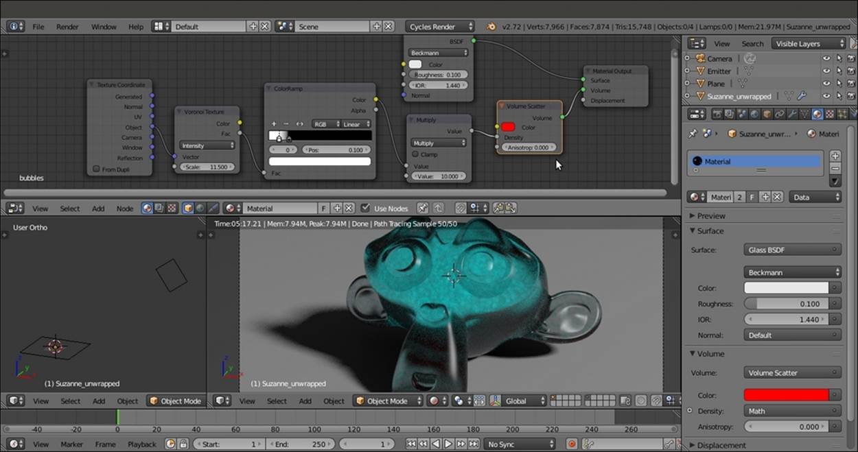
The previously cloudy volume covered with a glass surface
13. Rename the material as Bubbles and save the file by naming it 9931OS_09_volume.blend. Have a look at the following screenshot:
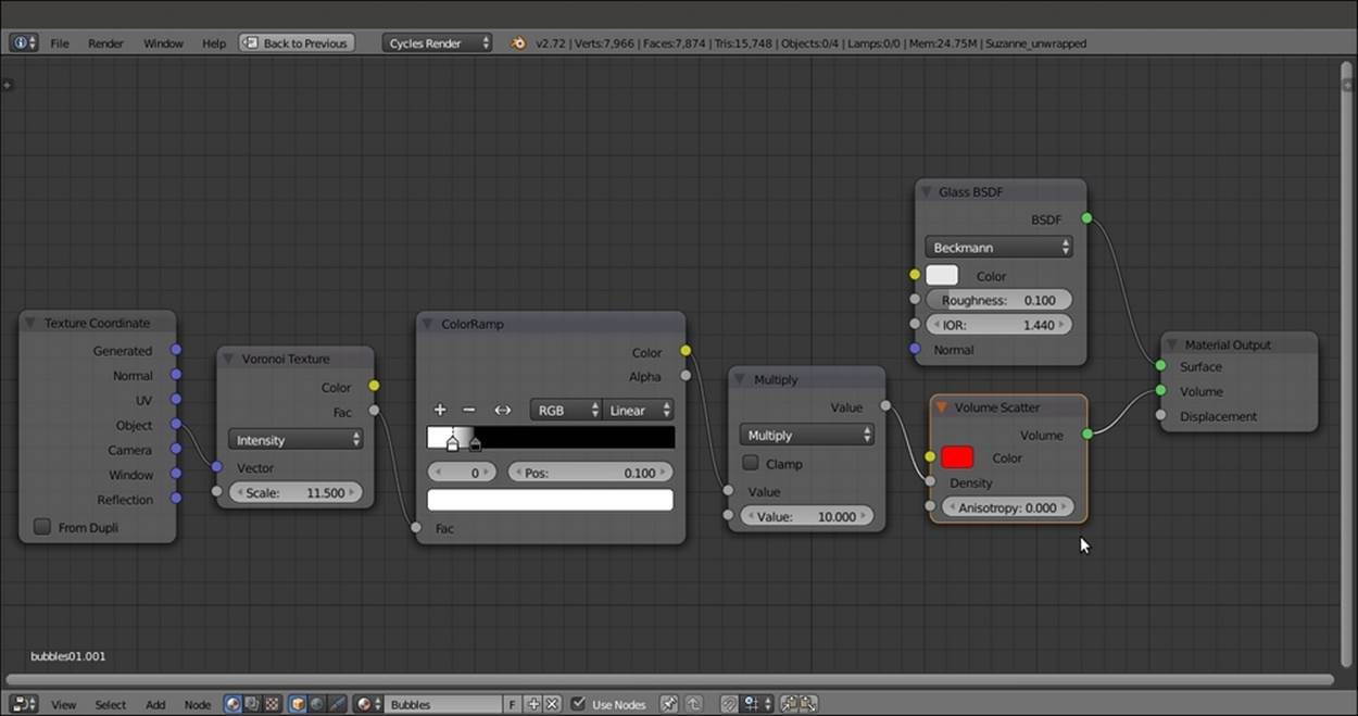
The overall network for the combined surface and volume material
So, for the previous material named Bubbles, we used the Volume Scatter node. What about the Volume Absorption node?
14. In the Node Editor toolbar, enable fake user for the Bubbles material, and click on the X icon button to delink the datablock. Then click on the New button.
15. Delete the Diffuse BSDF shader node and add a Volume Absorption node (press Shift + A and navigate to Shader | Volume Absorption). Then connect it to the Volume input socket of the Material Output node.
16. To make a comparison with the Volume Scatter node, raise the Density value of the Volume Absorption node to 10.000 and set the Color values for R to 1.000, G to 0.000, and B to 0.000. Have a look at the following screenshot:
Different effects of the Volume Absorption node
17. Add a Texture Coordinate node (press Shift + A and navigate to Input | Texture Coordinate), a Voronoi Texture node (press Shift + A and navigate to Texture | Voronoi Texture), two Math nodes (press Shift + A and navigate to Converter | Math), and aGlass BSDF shader (press Shift + A and navigate to Shader | Glass BSDF).
18. Connect the Object output of the Texture Coordinate node to the Vector input socket of the Voronoi Texture node, and the Fac output of this node to the first Value input socket of the first Math node. Set the second Value to 0.100, set Operation to Less Than, and connect its output to the first Value input socket of the second Math node. Set the second Value to 12.800 and the Operation to Multiply.
19. Connect the output of this Multiply-Math node to the Density input socket of the Volume Absorption node, and rename the material as algae. Here is a screenshot for your reference:
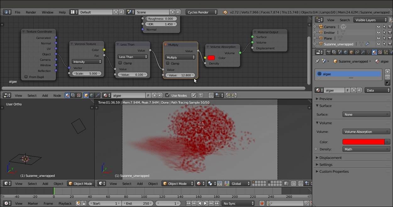
The density of the Volume Absorption node driven by the Voronoi Texture output
20. Set the Scale value of the Voronoi Texture node to 3.500, change the Color of the Volume Absorption node for R 0.045, G 0.800, and B 0.113, and connect the output of the Glass BSDF shader node to the Surface input socket of the Material Output node. Set the IOR value to 1.440 and the Roughness value to 0.100 as shown in the following screenshot:
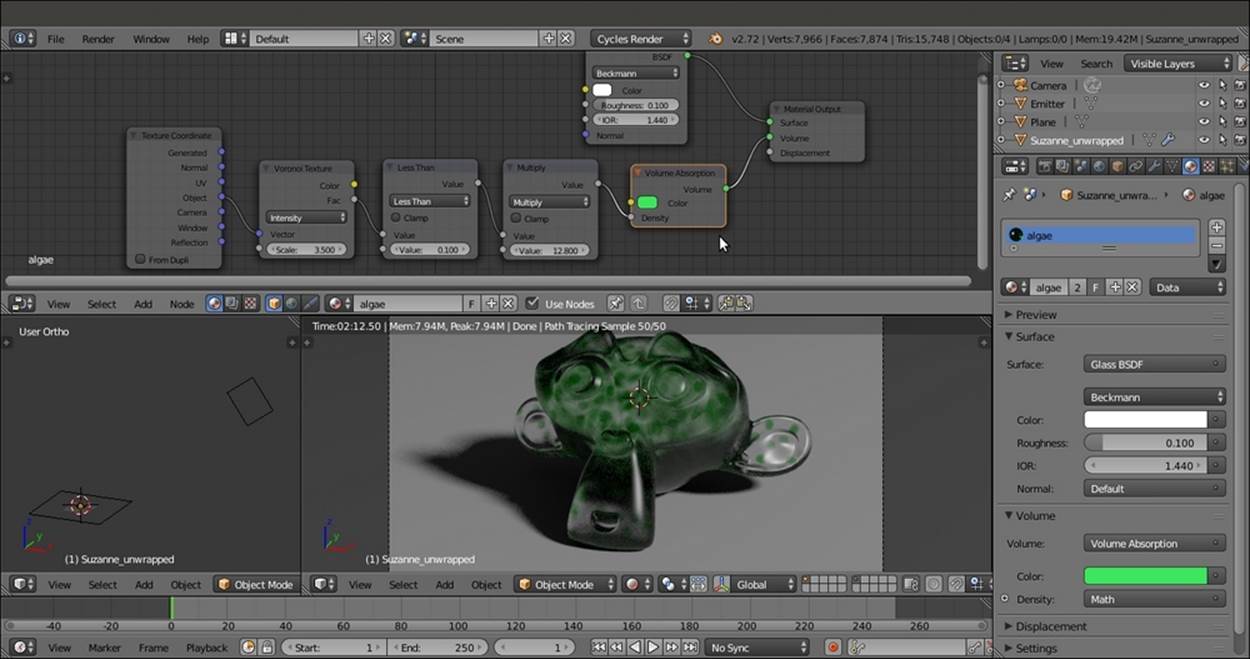
Different colors and a glass cover for the absorption volumetric material
21. In the Node Editor toolbar, enable fake user for the algae material, and then click on the 2 icon (Display number of users for this data) to create a duplicate of the material, named algae.001.
22. Rename the material as emitting_volume and substitute the Volume Absorption node with an Emission node (press Shift + A and go to | Shader | Emission). Connect the output of the Multiply-Math node to the Color input socket, and set the Strengthvalue to 0.050.
23. Disable the visibility of the sixth scene layer to hide the Emitter mesh-light, and go to the Render window. In the Light Paths subpanel, enable both the Reflective Caustics and Refractive Caustics items. Here is a screenshot for your reference:
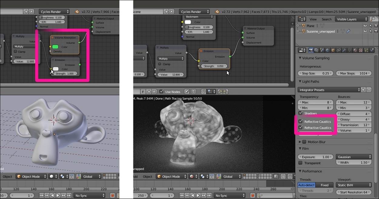
Substituting the Volume Absorption node with an Emission node as the volume material
24. Enable fake user for the emitting_volume material and save the file.
How it works...
In this tour recipe, we saw the three shaders used for the volumetric attribute of a material in Cycles, that is, the Volume Scatter, Volume Absorption, and Emission shaders (we have already seen the Emission shader the previous chapters, and it is commonly used in Lamps and mesh-lights).
The Volume Scatter and Absorption shaders do exactly what their names say, as we saw in the examples. If we give them a color other than black, gray, or white, the Volume Scatter shader returns a complementary hue, while the Volume Absorption shader returns the same hue we set up.
About the Density value, remember that the higher the value, the more particles inside the volume. This allows for simulation of very light and rarefied vapors or very dense clouds of smoke, where the material looks almost solid.
There's more...
A Volume can be associated not only with objects but also with the World. This allows for several effects, for example, mist, or the famous God's rays. They are obtained by simply scattering light in the air of a Spot lamp.
The setup is really simple and intuitive: a Volume Scatter node connected to the Volume input socket of the World Output node. Have a look at the following screenshot:
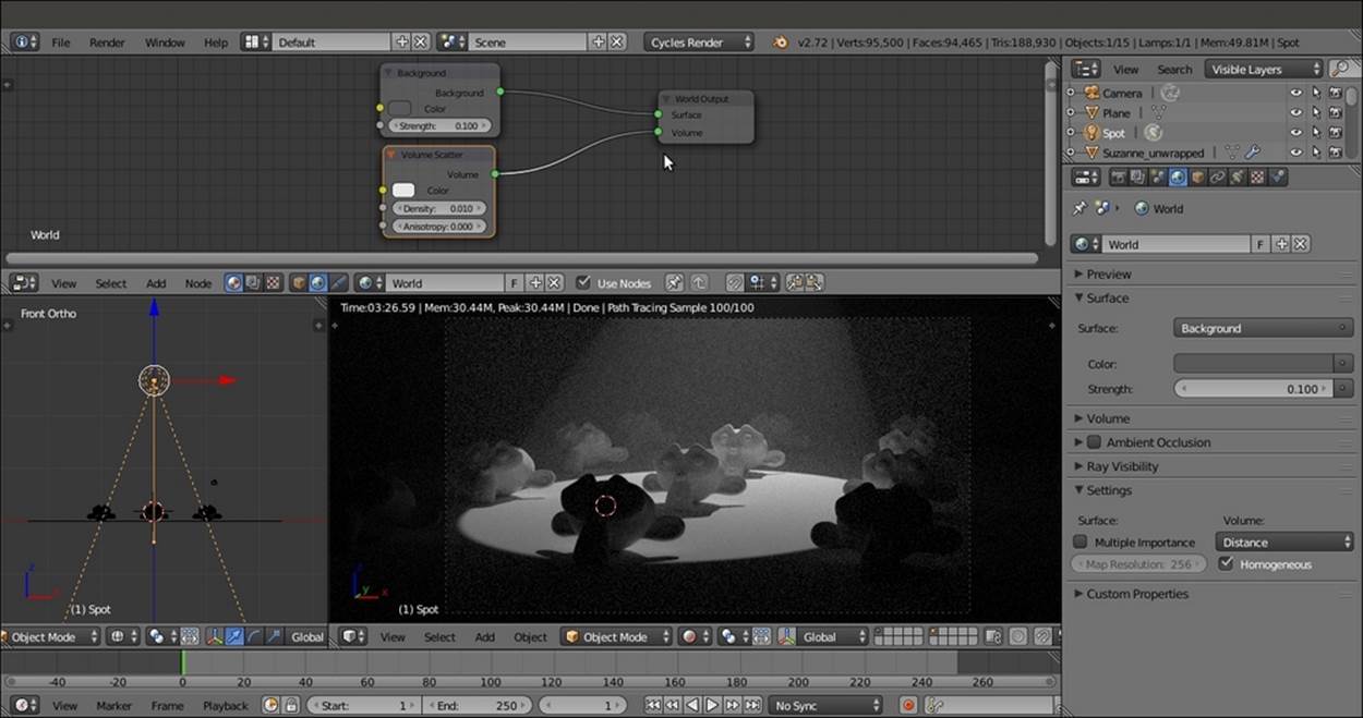
The cone of a Spot lamp visible through the ambient volume material
The Density value of the Volume Scatter node in this case is set very low (0.010) to allow the light of the Spot lamp to shine through.
Open the 9931OS_09_volume_ambient.blend file to have a look.
See also
· http://wiki.blender.org/index.php/Doc:2.6/Manual/Render/Cycles/Materials/Volume
Creating a cloud volumetric material
The natural consequence of a volumetric material is (quite obviously) clouds.
A simple way to create clouds in Cycles is by modeling the desired shape and then assigning an appropriate volumetric material. In the following screenshot, you can see this method applied to the usual Suzanne mesh:
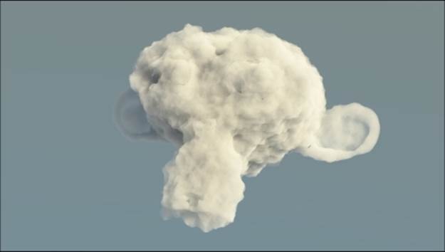
The volumetric Suzanne cloud as it appears in the final rendering
Getting ready
Start Blender and open the 9931OS_09_cloud_start.blend file, where there is the Suzanne_cloud object with two Emitter mesh-lights and a bright World set with a Sky Texture.
1. Go to the Object modifiers window and raise the Subdivisions level of the Subdivision Surface modifier from 2 to 3 for both Preview and Render.
2. Assign a new Subdivision Surface modifier. Set the Subdivisions level to 2.
3. Assign a Displace modifier. Click on the Show texture in texture tab button to the right of the New button to switch to the Texture window.
4. Click on the New button under the Displace item, then click on the Type slot to switch from Image or Movie to Clouds. Set the Size to 0.35 and the Depth to 3.
5. Go back to the Object modifiers window and click on the Vertex Group slot to select the rest item. Then set the Strength value to 0.400.
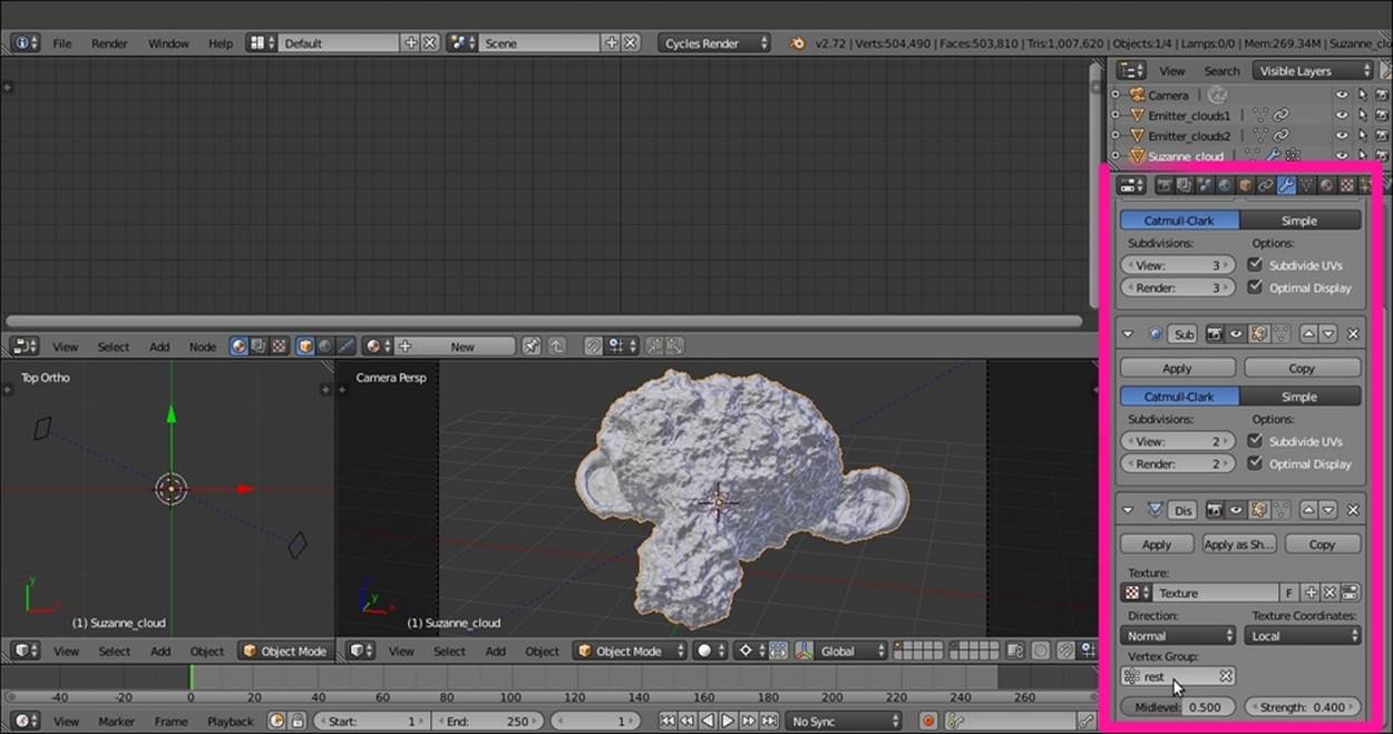
The displaced Suzanne cloud seen in the Solid Viewport Shading mode and the assigned modifiers in the main properties panel to the right
How to do it...
After creating the cloud shape, let's make a start on the material:
1. Ensure that the Suzanne_cloud object is still selected, and click on the New button in the Node Editor toolbar or in the Material window under the main Properties panel.
2. In the Node Editor window, select and delete the Diffuse BSDF shader node.
3. Add a Volume Scatter node (press Shift + A and navigate to Shader | Volume Scatter), a Volume Absorption node (press Shift + A and navigate to Shader | Volume Absorption), and an Add Shader node (press Shift + A and navigate to Shader | Add Shader).
4. Connect the output of the Volume Absorption node to the first Shader input socket of the Add Shader node, and the Volume Scatter output to the second Shader input socket. Connect the output of the Add Shader node to the Volume input socket of theMaterial Output node.
5. Add a Mix Shader node (press Shift + A and navigate to Shader | Mix Shader) and paste it between the Add Shader node and the Material Output node. Connect the output of the Volume Scatter node to the second Shader input socket of the Mix Shadernode. Set the Fac value to 0.700.
6. Add a Value node (press Shift + A and navigate to Input | Value) and an RGB node (press Shift + A and navigate to Input | RGB). Connect the Value output to both the Density input sockets of the Volume Absorption and Volume Scatter nodes. Set the input value to 5.000.
7. Connect the output of the RGB node to the Color input sockets of the Volume Absorption and Volume Scatter nodes. Set the color values for R to 0.890, G to 0.866, and B to 0.832.
8. Under the Material windows, go to the Settings subpanel and enable the Homogeneous item.
9. Go to the Scene window, and under the Color Management subpanel, enable the Use Curves item. Then click on the curves window to create a new control point. Set its coordinates as X to 0.67206 and Y to 0.88125. Click again to create a new control point, and set the coordinates as X to 0.31579 and Y to 0.46875. Have a look at the following screenshot:
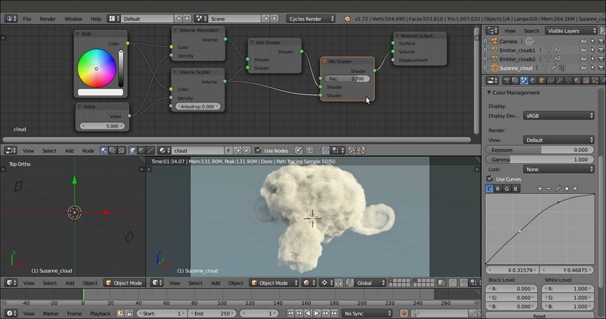
The Rendered preview of the Suzanne cloud and the material network in the Node Editor window
How it works...
Most of the effect of this material is because of the Displace modifier deforming the Suzanne mesh in order to resemble the shape of a Suzanne cloud. The material itself is simply a combination of the Volume Scatter and the Volume Absorption shader, first added by the Add Shader node and then with a Mix Shader node to further control the mixing of the scattering in the whole shader.
The Vertex Group, rest, selected in the Displace modifier slot is simply a group with lower weight going towards the ears, because they are quite thin, and the displacement we're using can easily cause bad mesh intersections.
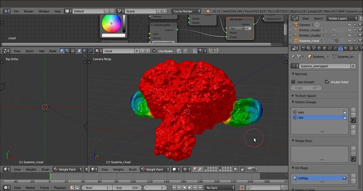
The Rest Vertex Group visible in the Weight Paint mode
In the last step, we enabled curves for the Color Management to obtain a brighter and more contrasted rendering of the cloud against the sky.
Creating a fire and smoke shader
In this recipe, we are going to see one of the most exciting effects we can obtain in Cycles—a fire and smoke simulation effect:
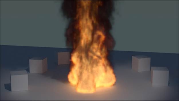
The fire and smoke shader as it appears in the final rendering when assigned to the Suzanne mesh
Getting ready
Start Blender and open the 9931OS_09_fire_smoke_start.blend file, where there is the Suzanne_unwrapped object leaning on a Plane and surrounded by five small Cubes, a Spot lamp, the Camera, and a medium-intensity World with a Sky Texture.
1. Go to the Render window, and under the Sampling subpanel, set the Preview samples to 50 and the Render samples to 100. Then go to the Dimensions subpanel and set the End Frame to 80. Under the Light Paths subpanel, enable the Reflective andRefractive Caustics items.
How to do it...
Let's start by creating the smoke simulation by a shortcut:
1. Select the Suzanne_unwrapped object, click on the Object item in the 3D viewport toolbar to go to Quick effects, and select the Quick Smoke item. Alternatively, press the spacebar, and in the search window, start typing Quick. Then select the Quick Smoke item from the menu as shown in the following screenshot:
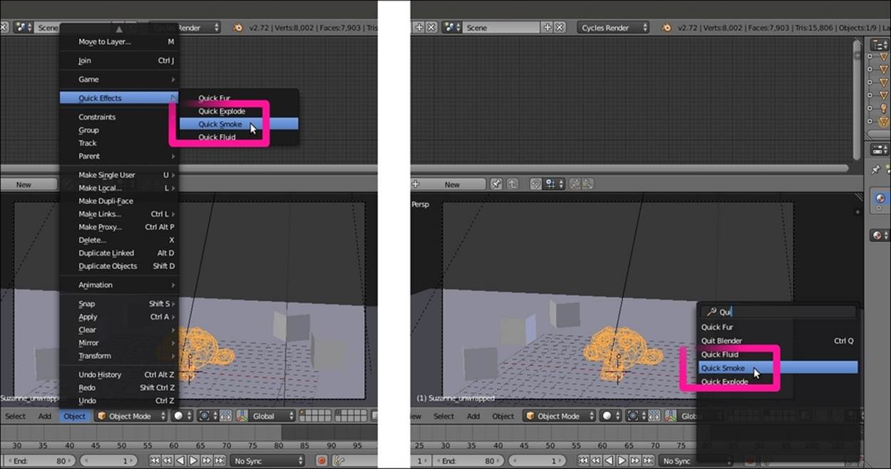
The Quick Effects menu
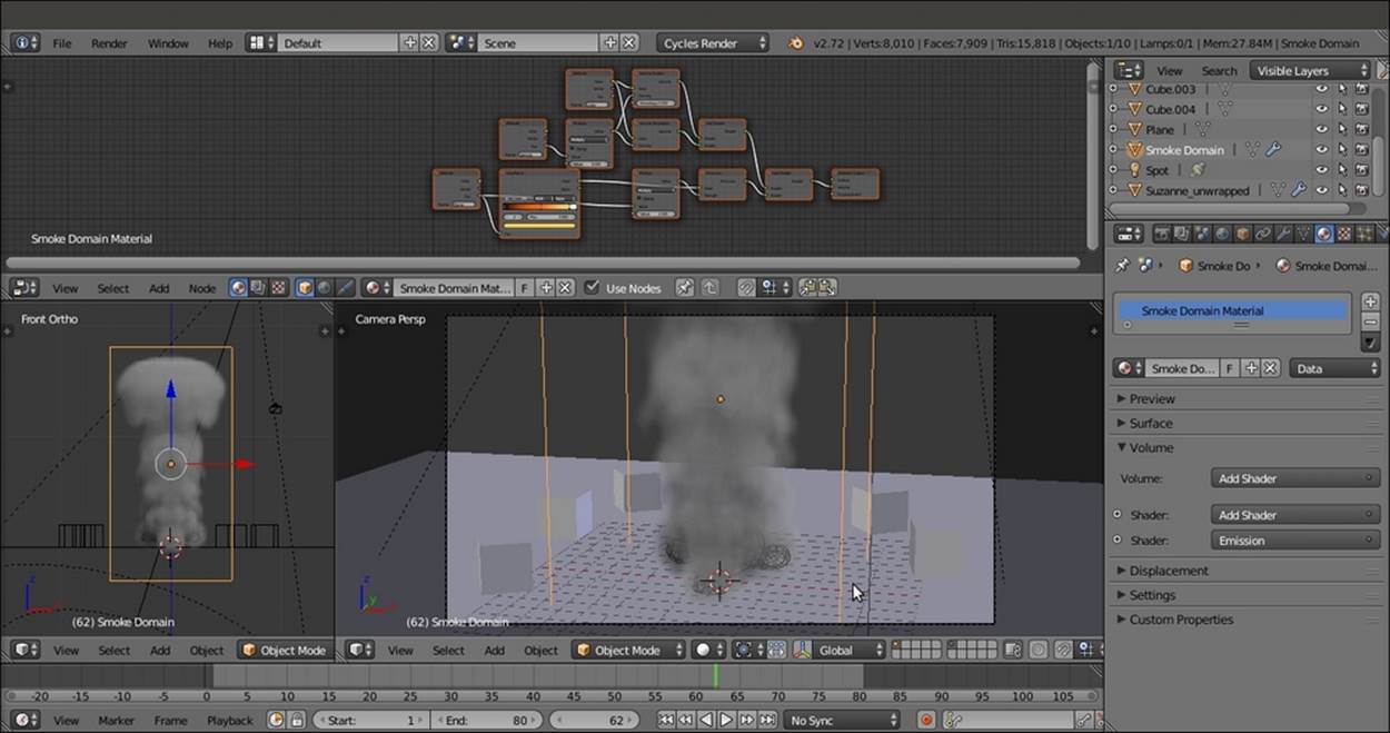
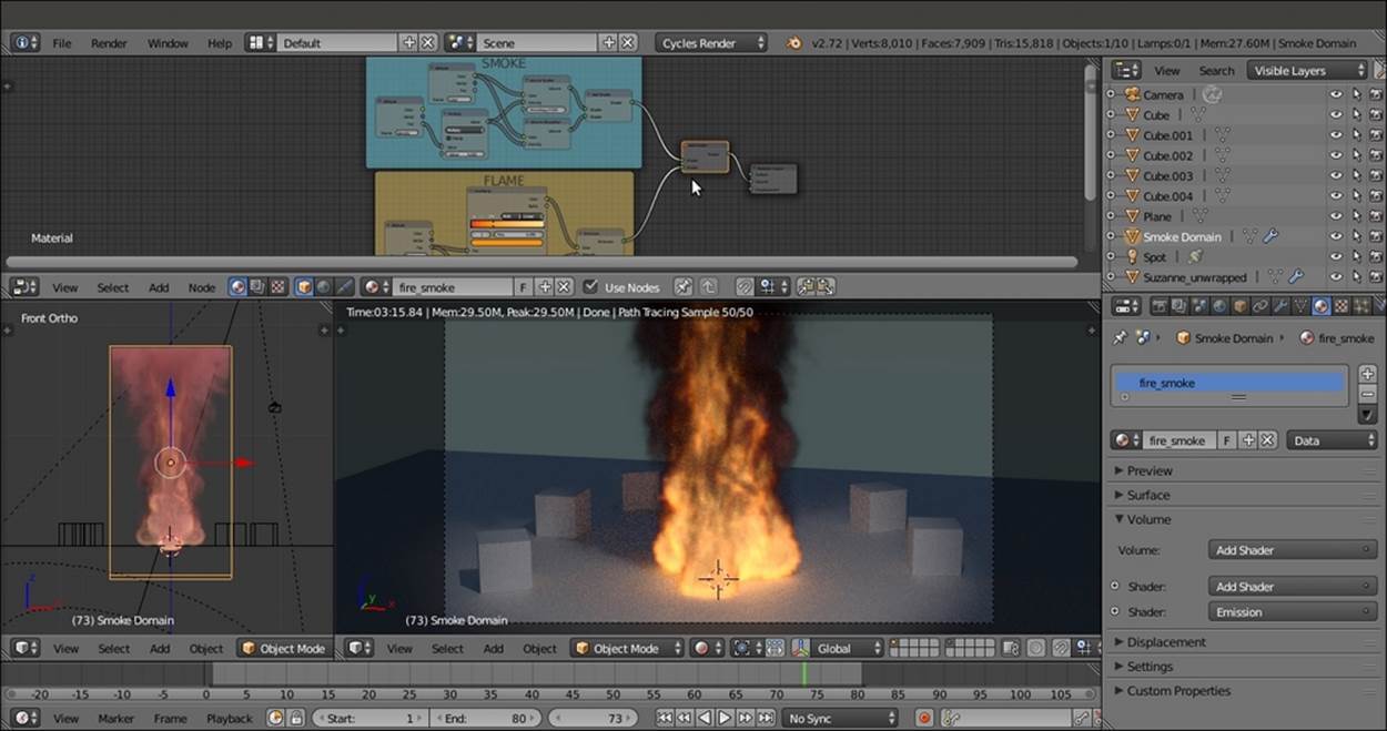
2. A Smoke Domain (the selected wire box around the Suzanne object) with a prepared fire/smoke material (Smoke Domain Material) is automatically set up on the selected object, and when you press the Play button in the Player Control on the Timelinetoolbar, the smoke simulation starts. Have a look at the following screenshot:
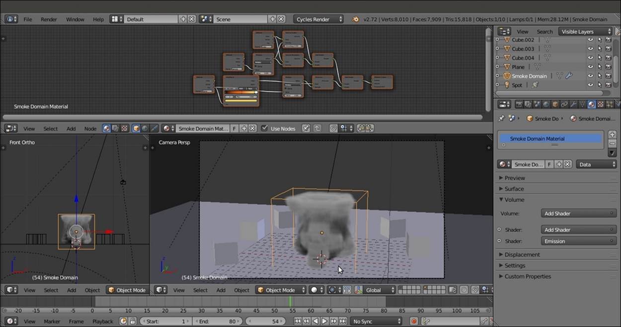
The smoke simulation: in the upper Node Editor window, the material being automatically created by the Quick Effects tool
3. Go back to frame 1 and scale the Smoke Domain to a larger size on the global z axis such that its top goes out of the Camera frame boundary. Scale it by 3.000 (press S, enter digit 3.000, then press Enter). Then move it 5 units upwards.
4. Go to the Physics window, and under the Smoke subpanel, set the Divisions value to 64. Then go to the Smoke Flames subpanel and set the Speed value to 2.00000, Smoke to 0.50000, and Vorticity to 1.00000. Restart the Play button to recalculate the cache. Have a look at the following screenshot:
The smoke simulation inside a bigger domain box
5. As all the 80 frames have been cached, go to the Physics window, and under the Smoke Cache subpanel, click on the Current Cache to Bake button.
6. Enable the Smoke Adaptive Domain and the Smoke High Resolution subpanels. Leave the default settings as they are.
7. With the mouse arrow in the Camera view, press Shift + Z to switch to the Rendered viewport shading mode. Have a look at the following screenshot:
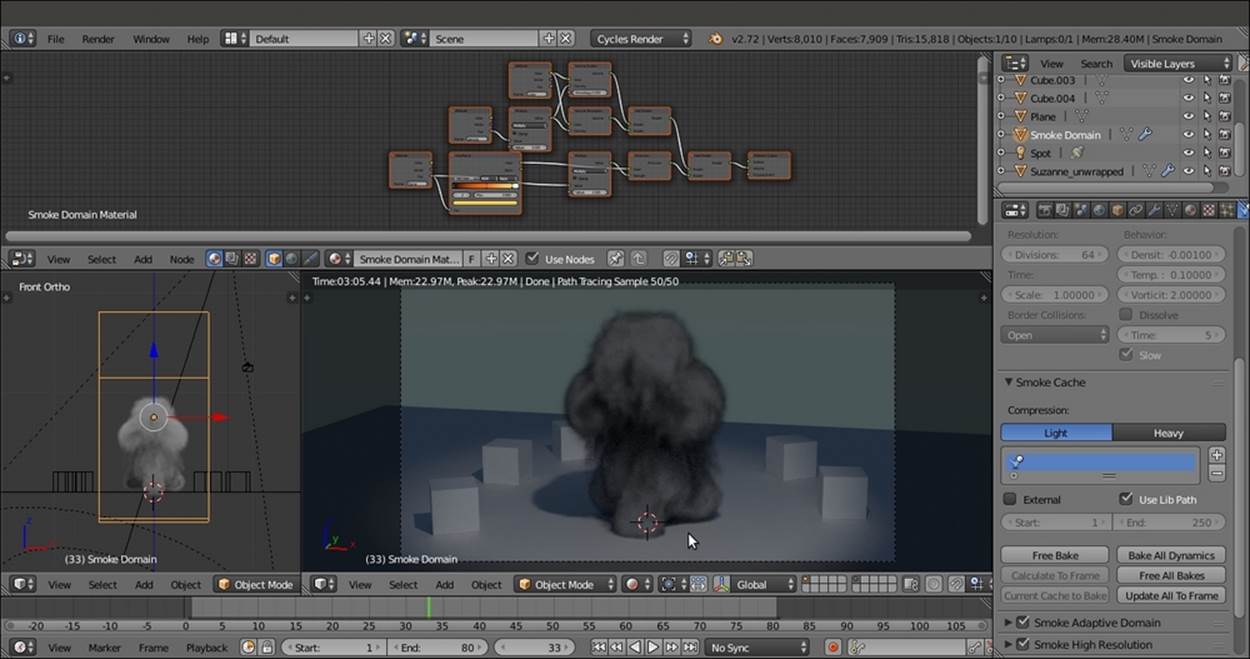
The smoke simulation seen in the Rendered preview
In the Rendered preview (be careful that the smoke is not supported by GPU yet), we can see the dark grey smoke, but what about the fire?
8. In the Physics window, under the Smoke Cache subpanel, click on the Free All Bakes button.
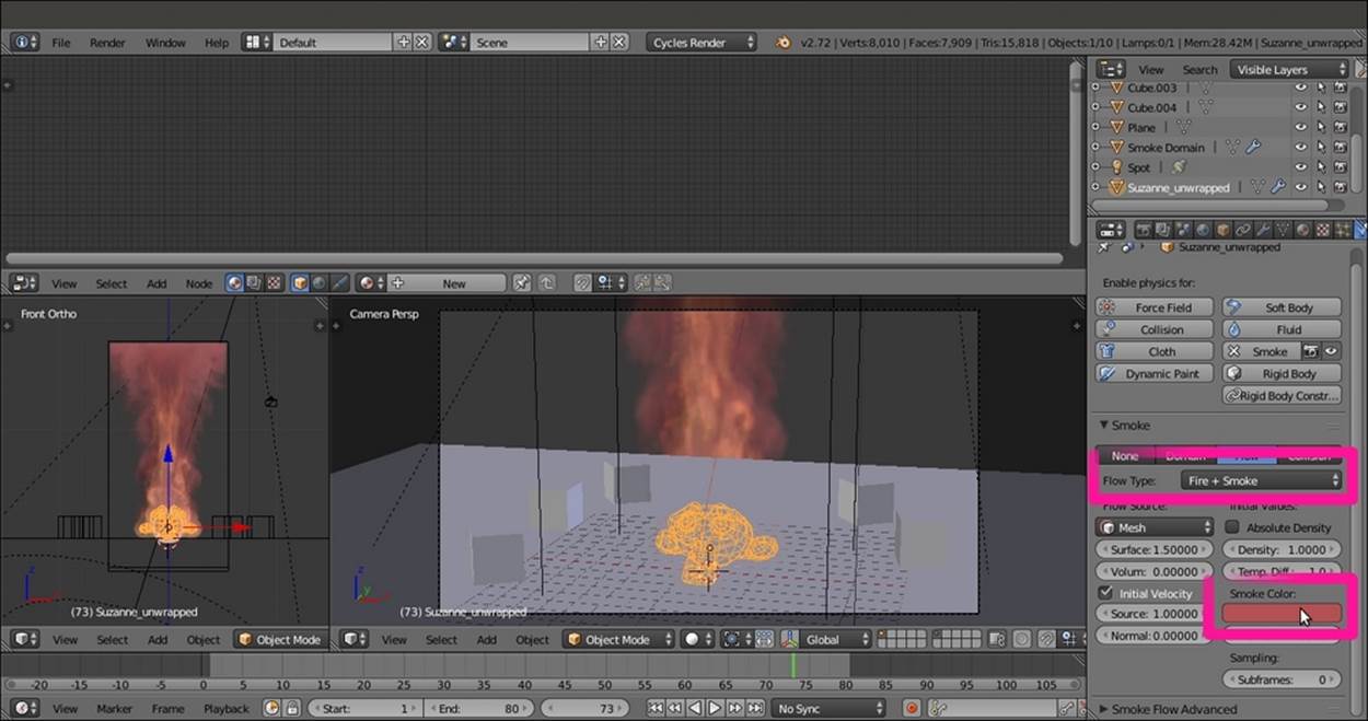
9. Go to the Outliner to select the Suzanne_unwrapped item. Then go to the Physics window again. Under the Smoke subpanel, click on the Flow Type slot and switch from Smoke to Fire + Smoke. Then click on the Smoke Color slot and change the color values for R to 0.700, G to 0.317, and B to 0.335. Have a look at the following screenshot:
10. Reselect the Smoke Domain object and click on the Play button to cache the smoke simulation again, this time with reddish smoke and also the fire. Then click on the Current Cache to Bake button again.
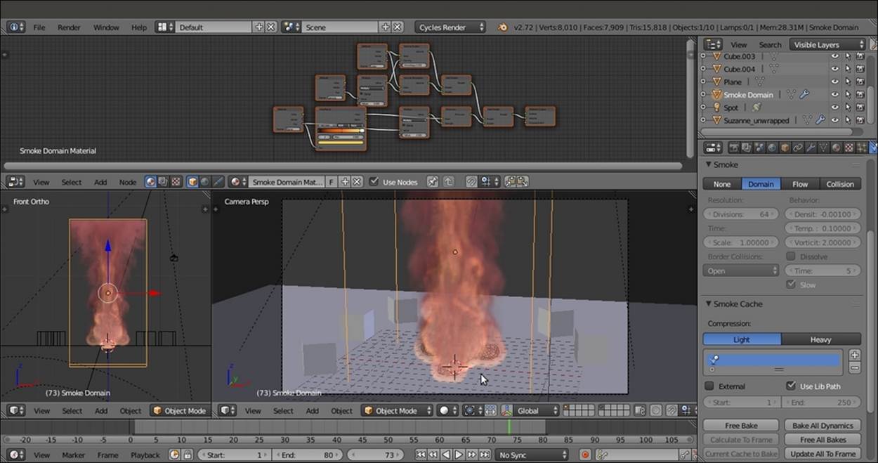
The new smoke (and fire) simulation
But this is a Cookbook about materials, so let's put aside the smoke simulation settings and concentrate on the material. To better understand how this works, let's delete the ready-made material and create a new material from scratch.
11. In the Node Editor toolbar, press Shift and click on the X button to unlink the Smoke Domain Material. Set the users to zero.
Now, setting the Camera view shading mode to Rendered shows only the Smoke Domain box as a solid object because no material is assigned to the simulation.
12. Click on the New button in the Node Editor window toolbar. Delete the Diffuse BSDF shader node and add a Volume Scatter node (press Shift + A and navigate to Shader | Volume Scatter). Connect it to the Volume input socket of the Material Outputnode.
13. Add an Attribute node (press Shift + A and navigate to Input | Attribute) and connect its Fac output to the Density input socket of the Volume Scatter node. In the Name field of the Attribute node, write density.
14. Add a Math node (Shift + A | Converter | Math), set the Operation to Multiply, and paste it between the Attribute and the Volume Scatter nodes. Set the second Value to 5.000.
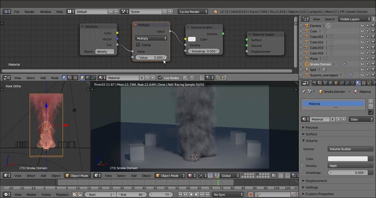
Building the smoke density after deleting the default Quick Effects material
15. Press Shift + D to duplicate the Attribute node, connect the duplicated node's output to the Color input socket of the Volume Scatter node. In the Name field, write color.
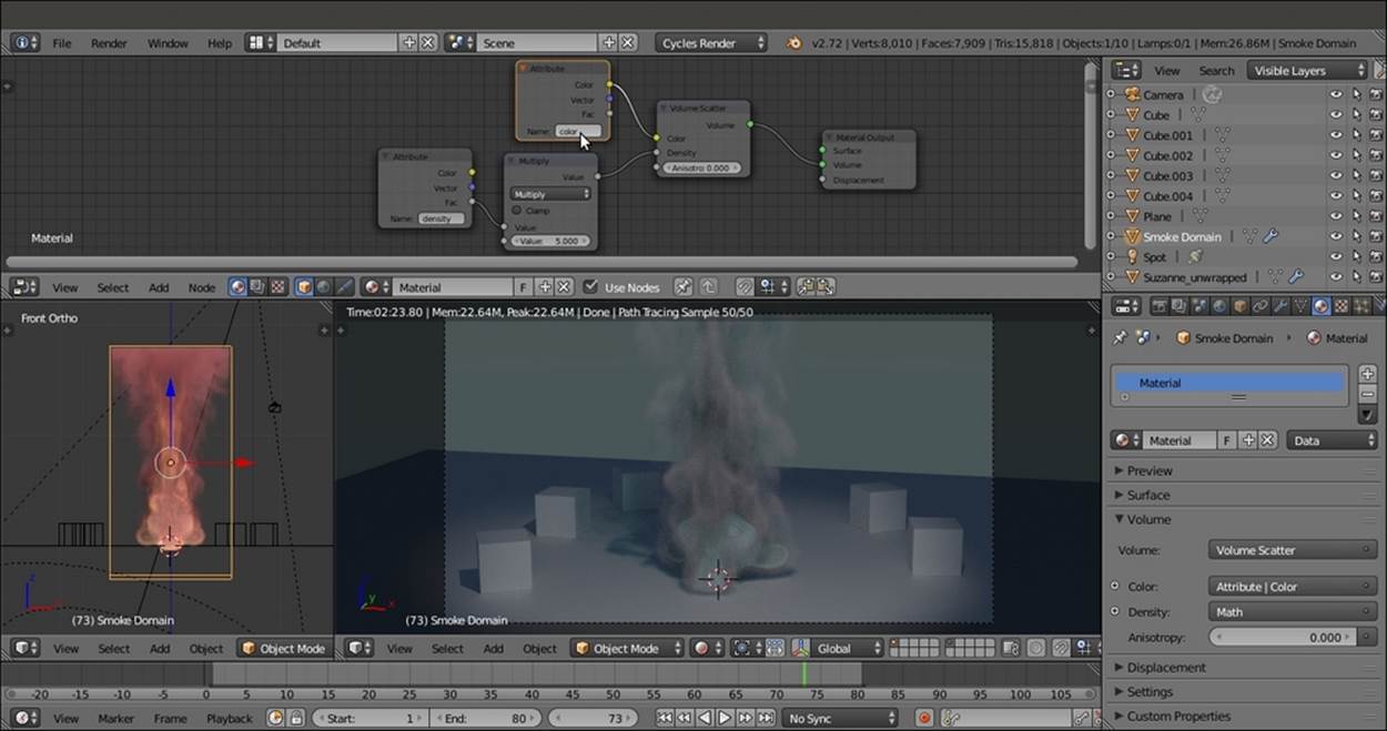
The smoke color
As you can see in the rendered preview, the smoke gets a bluish coloration, with the complementary color (orange) getting scattered.
1. Add a Volume Absorption node (Shift + A | Shader | Volume Absorption) and an Add Shader node (Shift + A | Shader | Add Shader). Paste the Add Shader node between the Volume Scatter and the Material Output nodes. Then connect the Volume Absorption output to the second Shader input socket of the Add Shader node.
2. Connect the Color output of the Color-Attribute node to the Color input socket of the Volume Absorption node, and the output of the Multiply node to the Density input socket of the Volume Absorption node as shown in the following screenshot:
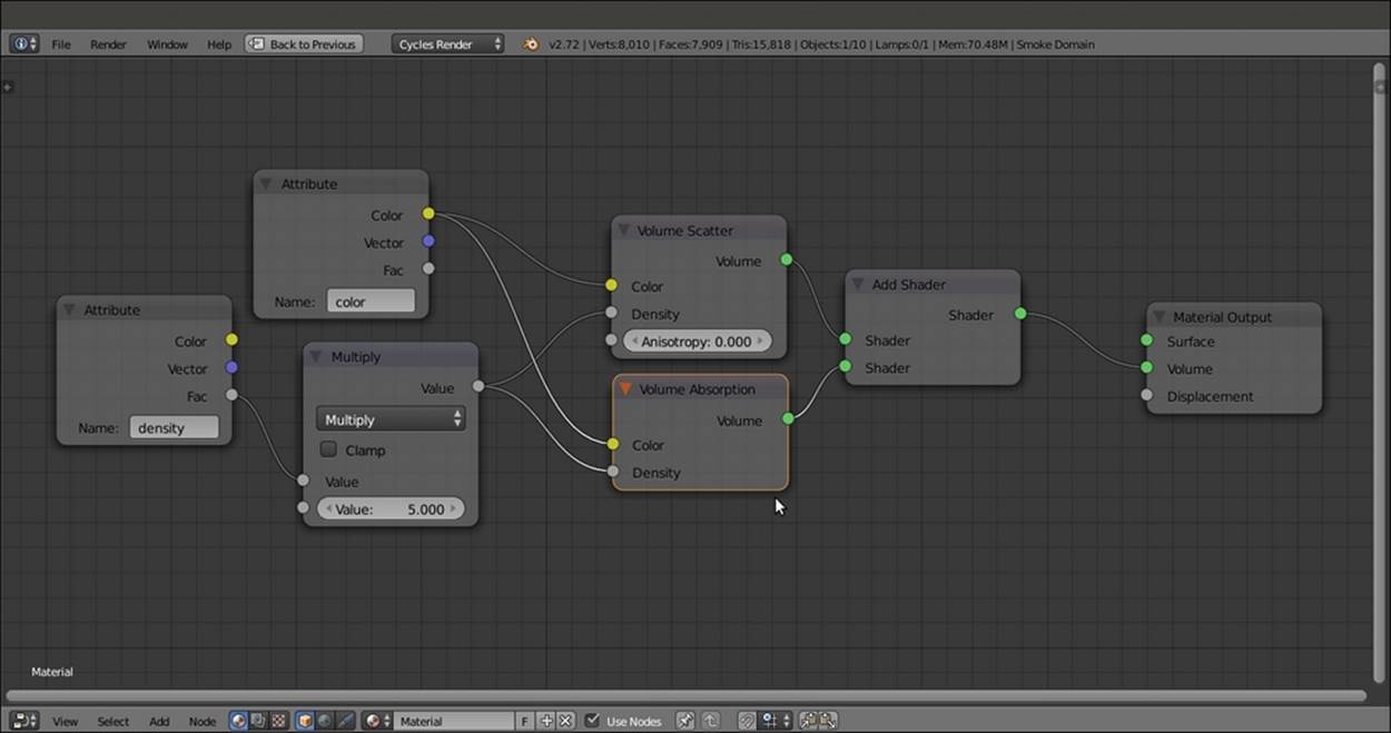
The complete smoke network
3. Parent all of these nodes, except the Material Output node, to a Frame. Label it as SMOKE.
4. Duplicate or add a new Attribute node, and in the Name field, write flame. Add an Emission shader (press Shift + A and navigate to Shader | Emission) and connect the Fac output to both the Strength and the Color input sockets of the Emission shader node.
5. Add a ColorRamp (Shift + A | Converter | ColorRamp) and paste it between the Attribute output and the Color input socket of the Emission node. Set the black color stop values for R to 1.000, G to 0.000, and B to 0.010. Then set the white color stop values for R to 1.000, G to 0.724, and B to 0.224. Add a new color stop and move it to the 0.290 position. Set the color values for R to 1.000, G to 0.280, and B to 0.000.
6. Add a Math node and paste it between the Attribute output and the Strength input socket of the Emission node. Set the Operation to Multiply and the second Value to 5.000.
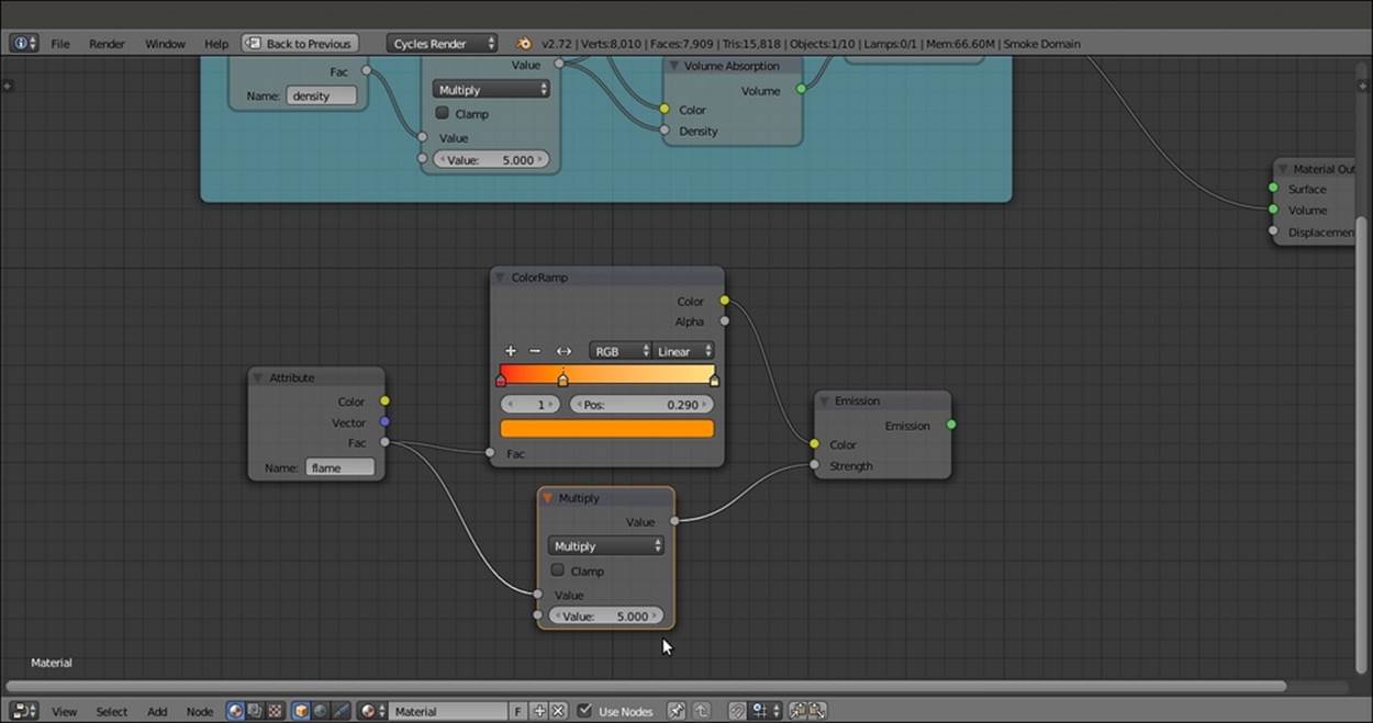
Starting to build the fire shader
7. Parent these four nodes to a new Frame labeled as FLAME.
8. Add an Add Shader node (press Shift + A and navigate to Shader | Add Shader) and paste it between the output of the Add Shader inside the SMOKE frame and the Material Output. Connect the output of the Emission shader inside the FLAME frame to the second Shader input socket of the last Add Shader node.
Smoke and fire shaders added
9. Rename the material as fire_smoke and save the file as 9931OS_09_fire_smoke_final.blend.
How it works...
Considering that we basically used the default settings for the fire and smoke simulation, the result was pretty good. To find out more about the different settings and types of smoke, take a look at the links provided in the See also section of this chapter.
We used the Quick Effects menu to let Blender automatically set up the smoke simulation for us. The steps usually involved are as follows:
· For the simulation domain, set an object that defines the bounds of the simulation volume. In our case, it was the Smoke Domain box in the wireframe viewport shading mode. It could be scaled, moved, or rotated if necessary.
· For the flow, set an object that determines where the smoke will be produced from, that is, the Suzanne_unwrapped object.
· Assign a material to the smoke. In our case, it was the automatically created Smoke Domain Material, which we then remade as the fire_smoke material.
· Bake the simulation by computing the cache for the required frames and then clicking on the Current Cache to Bake button.
· Save the blend file.
The fire_smoke material we set in the Node Editor is made exactly as shown in the previous volume recipes of this chapter. It consists of all the three shader nodes that can be used for a Volume: the Volume Scatter, the Volume Absorption and the Emissionshaders, driven by the flame, density and color attributes we wrote in the Name field of the Attribute nodes and coming from the smoke simulation.
See also
· http://wiki.blender.org/index.php/Doc:2.6/Manual/Physics/Smoke
· https://cgcookie.com/blender/lessons/02-cycles-fire-and-smoke/
· http://www.blendernation.com/2014/04/14/rendering-smoke-and-fire-in-cycles/
Creating a shadeless material in Cycles
In this recipe, we will create a shadeless material, which is a material that behaves as self-illuminated but does not actually emit any light on the nearby objects.
In the following screenshot, we can see the difference between a Plane with a shadeless material and a Plane with an emitting material:
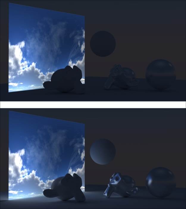
A shadeless Plane and an emitting Plane in comparison
At the top, the cloudy sky image is perfectly self-illuminated and visible, but it's neither affecting the Spheres or the Suzannes nor the floor Plane (nevertheless slightly visible because of a low intensity World).
This is the reason a shadeless material is perfect for backdrop elements mapped on Planes (or more often on unwrapped half-spheres called domes) to simulate skies, clouds, and even distant trees. It can also simulate forests and mountains in the background of a scene.
In Blender Internal, obtaining a shadeless material is very simple. Enabling the appropriate item in the material panel is enough. In Cycles, there are two methods to obtain this effect: one based on the material and the other based on the Ray Visibility subpanel in the Object window, under the main Properties panel.
Getting ready
Start Blender and open the 9931OS_09_start.blend file. Then follow these steps:
1. Go to the Render window, and under the Sampling subpanel, set the Samples to 50 for Preview and 100 for Render.
2. Set the Camera view to the Rendered shading mode by pressing Shift + Z with the mouse arrow in the viewport.
3. Go to the World window and set the Background strength to 0.200.
4. Go to Outliner and select the Emitter object. In the Node Editor window, set the Strength of the Emission shader node to 0.100.
5. Select the Plane object, and in the Material window under the main Properties panel to the right, replace the Diffuse BSDF shader with a Glossy BSDF shader node. Switch the Distribution of this node from GGX to Beckmann and set the Roughnessvalue to 0.200.
6. Select the Suzanne_unwrapped object and click on the New button in the Node Editor window toolbar, or in the Material window under the main Properties panel to the right.
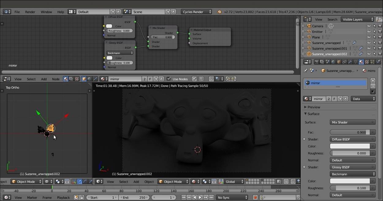
7. With the mouse arrow in the bottom-left corner of the 3D window, press the 7 key in the numeric keypad to switch to the Top Ortho view. Press Shift + D to duplicate the Suzanne mesh, and move it to the left of the scene. Rotate it to accommodate it close to the original mesh. Click on the 2 button to the side of the Material datablock in the Node Editor window toolbar to make it single-user.
8. In the Material window, switch the Diffuse BSDF node with a Mix Shader node. In the first Shader slot, select a Diffuse BSDF node, and in the second Shader slot, select a Glossy BSDF shader node. Set the Glossy distribution to Beckmann, theRoughness value to 0.100, and the Fac value of the Mix Shader node to 0.900. Rename the material as mirror.
9. Press Shift + D to duplicate the mirror Suzanne mesh, and move it to the right of the scene, close to the original mesh.
The three Suzannes on the floor Plane in the dark
How to do it...
Let's start with the first method, based on the material:
1. Select the original Suzanne_unwrapped mesh, which is in the middle, and click on the New button in the Node Editor window toolbar. In the Material window, switch the Diffuse BSDF shader with an Emission shader. Add an Image Texture node (pressShift + A and navigate to Texture | Image Texture) and connect its Color output to the Color input socket of the Emission node.
2. In the Rendered Camera view, the original Suzanne mesh is emitting pink light on the scene. Pink is the default color that Blender uses to tell us that we haven't loaded an image texture yet.
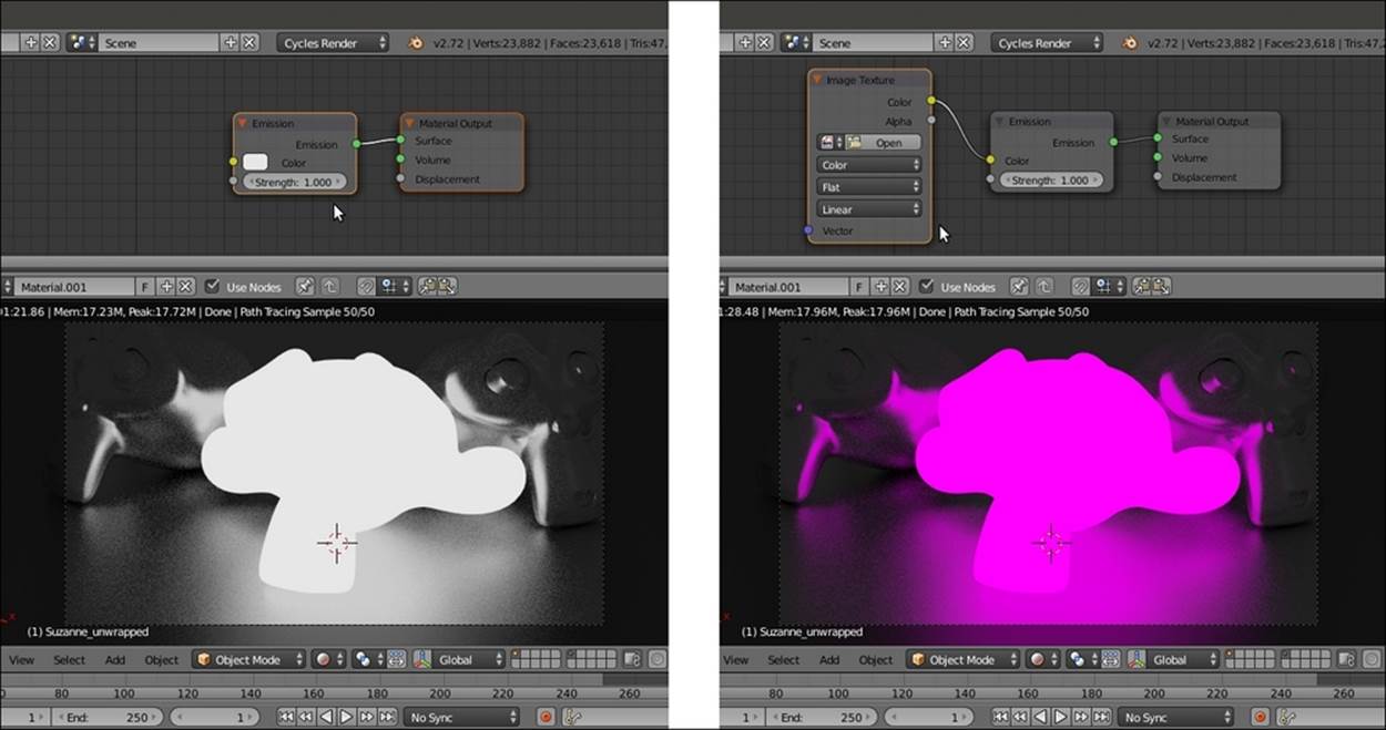
Suzanne emitting light and the texture being missing
3. Click on the Open button of the Image Texture node, browse to the textures folder, and load the teddybear.png image (which was used in Chapter 8, Creating Organic Materials).
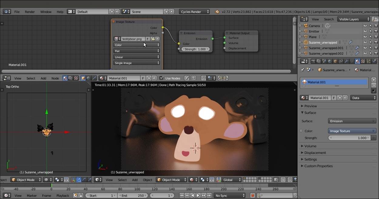
Suzanne with the UV-mapped texture
4. In the Node Editor window, add a Mix Shader node (press Shift + A and navigate to Shader | Mix Shader) and paste it between the Emission node and the Material Output node.
5. Add a Light Path node (press Shift + A and navigate to Input | Light Path) and connect its Is Camera Ray output to the Fac input socket of the Mix Shader node. The Suzanne mesh turns totally black (no material) but still lights the scene based on theteddybear.png image's values.
6. Switch the connection of the Emission node from the first Shader input socket of the Mix Shader node to the second Shader input socket.
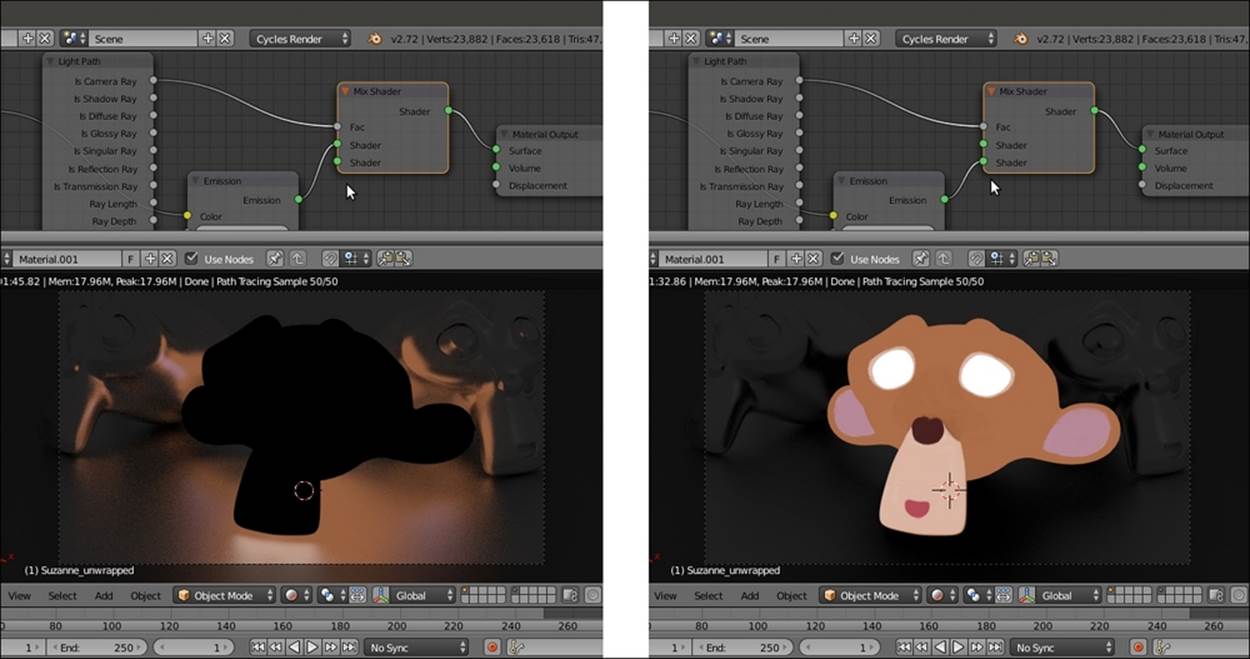
Inverting the order of the connections in the Mix Shader node
At this point, the shadeless Suzanne is still affecting the surrounding objects. It's reflected as a black object by the floor and by the mirror Suzannes. In fact, the output of the first empty input socket of the Mix Shader node is a black color because there is no material at all.
To prevent the shadeless Suzanne from getting reflected, follow these steps:
1. Add a Transparent shader node (press Shift + A and navigate to Shader | Transparent BSDF) and connect it to the first Shader input socket of the Mix Shader node.
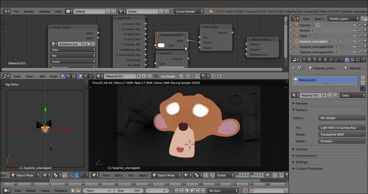
The totally shadeless Suzanne
2. Rename the material as shadeless and save the file as 9931OS_09_shadeless.blend.
How it works...
Thanks to the Is Camera Ray output of the Light Path node, all the light rays from the Camera that directly hit the Suzanne mesh are rendered with the Emission material brightness (because this material has a value equal to 1, which is due to its connection to the second Shader socket of the Mix Shader node). For the other kind of rays (reflected, transmitted, and so on, first socket = 0 value) there is no emitting material coming from the Suzanne mesh. Actually, there is initially no material at all, and this gives a black, reflected Suzanne. Following this, to avoid the black reflections, a Transparent BSDF shader has been connected to the first socket of the Mix Shader node.
There's more...
The second method to obtain a shadeless object is as follows:
1. Starting from the preceding file, select the Suzanne mesh, and in the toolbar of the Node Editor window, click on the F button on the right side of the material name data block to assign a fake user (this is to keep the material saved in the blend file even if not assigned to anything). Then click on the X icon (to unlink the datablock).
2. Now click on the New button to create a new material. In the Material window under the Properties panel, switch the Diffuse BSDF with an Emission shader node.
3. In the Node Editor window, add an Image Texture node (press Shift + A and navigate to Texture | Image Texture) and connect its Color output to the Color input socket of the Emission shader.
4. Click on the Open button on the Image Texture node to load the teddybear.png image texture.
At this point, we are at the same stage as step 2 of the first method. We have created a light emission material based on the image texture mapped on the Suzanne mesh.
5. Now go to the Object window under the main Properties panel to the right of the screen. In the Ray Visibility subpanel (usually the last at the bottom) uncheck the Diffuse, Glossy, Transmission, Volume Scatter and Shadow items.
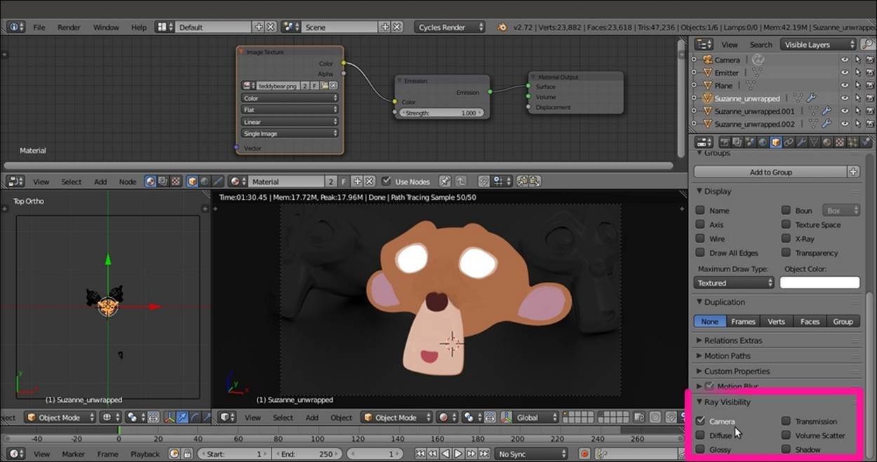
The shadeless Suzanne obtained through the Ray Visibility subpanel
So basically, only the Camera item is active now. Simple, quick, and effective!
Creating a fake immersion effect material
In this recipe, we will create a material to give the effect of an object immersed in a substance becoming more and more opaque as the depth increases, for example, murky water.
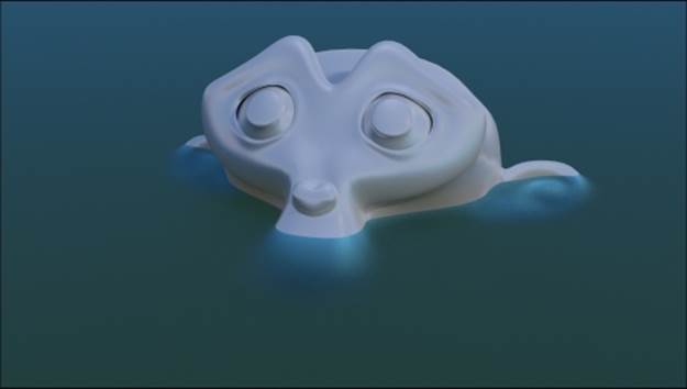
The murky water effect as it appears in the final rendering
Getting ready
Start Blender and open the 9931OS_09_start.blend file. Then follow these steps:
1. Go to the World window and click on the little dotted square on the right side of the color slot. From the menu, select Sky Texture. Then set the Strength value to 0.500.
2. Select the Plane, rename it as water, and move the Location value of Z to 1.17000. Then press Shift + D to duplicate it, rename it as bed, and move the Location value of Z to -2.00000.
How to do it...
Let's go ahead and create the different materials:
1. Go to the Material window and select the Suzanne_unwrapped mesh. In the Node Editor window toolbar, click on the New button, and rename the material as (simply) Suzanne. In the Material window under the main Properties panel, switch the Diffuse BSDF shader with a Mix Shader node. In the first Shader slot, select a Diffuse BSDF shader node, and in the second Shader slot, select a Glossy BSDF shader node.
2. Set the Glossy distribution to Beckmann and the Roughness value to 0.100. Then set the Fac value of the Mix Shader node to 0.600.
3. Select the bed Plane and click on the New button in the Node Editor window toolbar. Rename the material as bed.
4. In the Material window, switch the Diffuse BSDF shader with an Emission shader node. Set the Color values for R to 0.800, G to 0.659, and B to 0.264. Then set the Strength value to 0.100.
5. Select the water Plane and click on the New button in the Node Editor window toolbar. Rename the material as water.
6. In the Material window, switch the Diffuse BSDF shader with a Mix Shader node. In the first Shader slot, select a Glass BSDF shader node, and in the second Shader slot, select a Transparent BSDF node.
7. Set the Glass BSDF node's Roughness value to 0.600 and the IOR to value 1.333. Then set the Color values for R to 0.185, G to 0.611, and B to 0.800.
8. Add a Light Path node (press Shift + A and navigate to Input | Light Path) and a ColorRamp node (press Shift + A and navigate to Converter | ColorRamp). Connect the Ray Length output to the Fac input socket of the ColorRamp and invert the position of the black-and-white color stops (that is, move the black color stop to the extreme right and the white color stop to the extreme left of the slider).
9. Connect the ColorRamp output to the Fac input socket of the Mix Shader node.
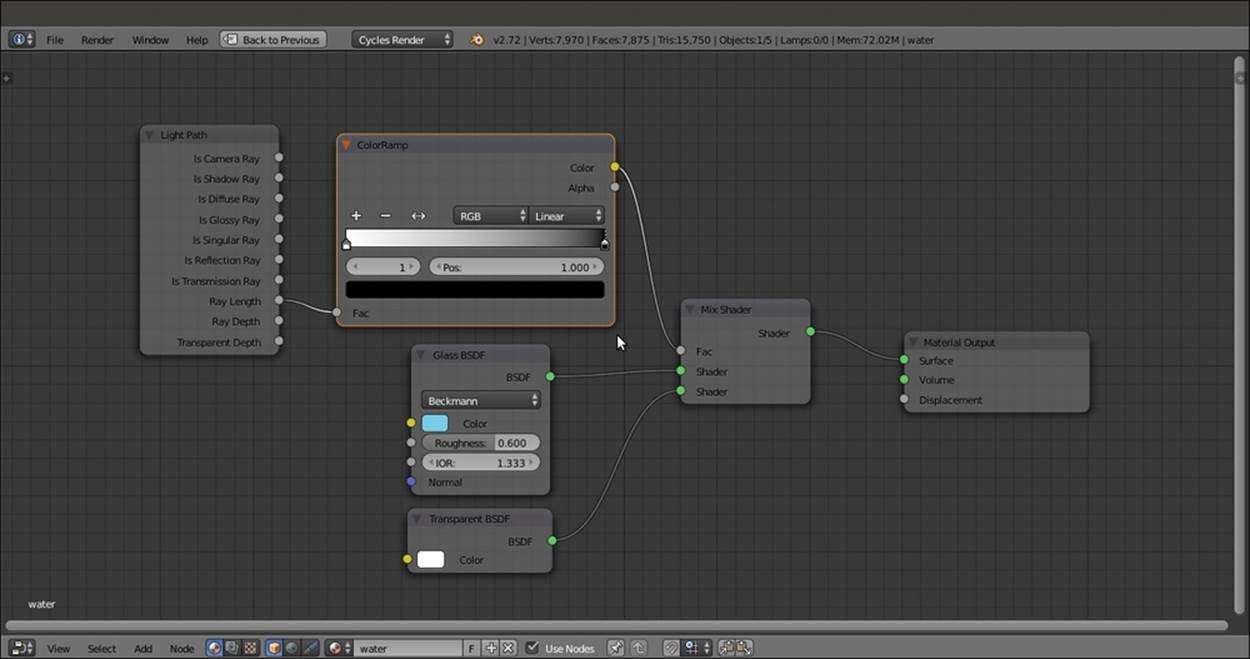
The murky water material network
How it works...
The effect happening on the water material is due to the Ray Length output, which returns the length of the light rays passing through an object, thus giving the thickness of that object. In our case, the distance from the water mesh surface to the far distance (from the Camera point of view, because the light rays originate from the Camera).
The gradient of the ColorRamp is mapped on the length of this Ray Length output (also clamped and inverted by the same ColorRamp node), connected to the Fac input socket of the Mix Shader node in order to work as a stencil map to smoothly blend the amount of the Glass shader with the amount of the Transparent BSDF shader node.
Thus, the transition from the Transparent shader to the Glass shader returns the impression of a volume of water becoming murkier as the distance of the object from the surface increases.
Creating a fake volume light material
In this recipe, we will create a material to fake the typical effect of a cone of light visible when passing through the dust suspended in the air, or falling from the sky on a cloudy day (the so-called God's rays) different from the real volumetric effect described in theThere's more section of the Using Cycles volume materials recipe. This is a fake—just a mesh and not a real light to be used for the scene. Therefore, a matching Lamp must be set for the real lighting, as shown in the already made blend file.
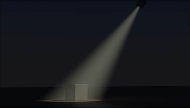
The fake volume cone of light as it appears in the final rendering
Getting ready
Start Blender and open the 9931OS_09_volumelight_start.blend file, where there is a scene set with a ground Plane, a Cube, the volumetric cone mesh (volume_light), a spot mesh object (spot_mesh), and an effective Spot lamp parented to the volume_light. The Spot lamp cone follows the shape of the volume_light, and its purpose is to light the Cube leaning on the ground Plane.
The volume light objects also have a brief animation of 98 frames. To see it, move the Time Cursor inside the Timeline window; to point the cone of light to the Cube, go to frame 81.
How to do it...
Let's go ahead with creating the light cone material:
1. Select the volume_light object and click on the New button in the Node Editor window toolbar, or in the Material window under the main Properties panel to the right. Rename the material as volume_light.
2. In the Material window, switch the Diffuse BSDF shader node with a Mix Shader node. Label it as Mix Shader1.
3. In the first Shader slot of the Mix Shader1 node, select a new Mix Shader node. Label it as Mix Shader2. In the second Shader slot, select a Transparent BSDF shader node.
4. Go to the Mix Shader2 node, and in the first Shader slot, select a Mix Shader node again (Mix Shader3). Connect the output of the Transparent BSDF node to the second Shader slot of the Mix Shader2 node.
5. Go to the Mix Shader3 node, and in the first Shader slot, select one more Mix Shader node (label it Mix Shader4). Connect the output of the Transparent BSDF node to the second Shader slot.
6. Go to the Mix Shader4 node, and in the first Shader slot, select one Emission node. Connect the output of the Transparent BSDF node to the second Shader slot of the Mix Shader4 node.
7. Set the color values of the Emission node for R to 0.769, G to 0.800, and B to 0.592. Then set the Fac value of Mix Shader4 to 0.800.
8. Add a Layer Weight node (press Shift + A and navigate to Input | Layer Weight) and connect its Facing output to the Fac input socket of the Mix Shader3 node. Set the Blend value to 0.900.
9. Add a ColorRamp node (press Shift + A and navigate to Converter | ColorRamp) and connect its color output to the Fac input socket of the Mix Shader2 node. Set the Interpolation to B-Spline and move the black color stop to position 0. Then move the white color stop to the extreme left.
10. Add a Value node (press Shift + A and navigate to Input | Value), label it as Intensity, and connect it to the Fac input socket of the Mix Shader1 node. Set the value to 0.400.
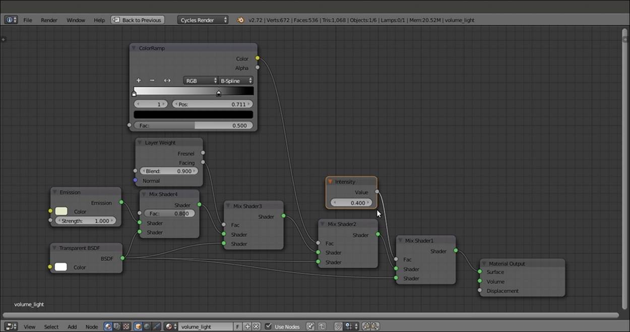
The entire material network
11. Save the file as 9931OS_09_volumelight_final.blend.
How it works...
The effect of light blending with the night is obtained by the various factors of blending of the Mix Shader nodes that cause the mixing of the Emission shader with the Transparent shader. The purpose of connecting the Value node to the Fac input of the Mix Shader1 node is to establish the intensity of the fake volumetric light. A value of 1.000 turns it off completely (be careful not to go beyond 1.000, otherwise the cone mesh will show up as a dark silhouette). On the contrary, values towards 0.000 (or even negative values) make it appear more and more intense.
Be careful with this simulation because being a mesh emitting light, it can produce strange and unrealistic effects if not carefully planned. Suppose you go to frame 62 and start the rendering. Then you will see that the volumetric cone mesh is intersecting the Cube even in those areas where a real light would create shadows.
See also
Since Cycles has been added to Blender, many artists have posted screenshots and tests for almost every possible kind of material. Especially on the Blender Artists forum, you will find a plethora of data and will discover different (and often better) ways to create the same materials that you have seen in this Cookbook.
Now it's up to you to create new, amazing materials and renderings that no one can avoid staring at. Blend on!
All materials on the site are licensed Creative Commons Attribution-Sharealike 3.0 Unported CC BY-SA 3.0 & GNU Free Documentation License (GFDL)
If you are the copyright holder of any material contained on our site and intend to remove it, please contact our site administrator for approval.
© 2016-2026 All site design rights belong to S.Y.A.