Blender Cycles: Materials and Textures Cookbook, Third Edition (2015)
Chapter 8. Creating Organic Materials
In this chapter, we will cover the following topics:
· Creating an organic-looking shader with procedurals
· Creating a wasp-like chitin material with procedural textures
· Creating a beetle-like chitin material with procedural textures
· Creating tree shaders – the bark
· Creating tree shaders – the leaves
· Creating a layered human skin material in Cycles
· Creating fur and hair
· Creating a gray alien skin with procedurals
Introduction
Following on from the natural materials we have seen in Chapter 3, Creating Natural Materials in Cycles, and in Chapter 5, Creating Complex Natural Materials in Cycles, it's now time to take a look at organic shaders.
Once again, while building the materials, we tried to use only the Cycles procedural textures. In several cases, this hasn't been the case by the way: on one side, because it hasn't been possible, and on the other side, because image maps usually work better than procedurals.
In any case, procedurals have often been added to the shader to refine the details or to add a natural-looking randomness to a pattern that repeats too much.
Creating an organic-looking shader with procedurals
In this recipe, we will create a sort of organic, disgusting-looking material, as shown in the following screenshot:
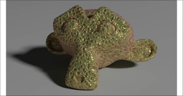
The disgusting organic material as it appears in the final rendering
Getting ready
Start Blender and open the 9931OS_08_start.blend file, where there is an already set scene with an unwrapped Suzanne primitive object leaning on a Plane, an Emitter mesh-light, and a Camera.
Go to the Render window, and in the Sampling subpanel, change Pattern from Sobol to Correlated Multi-Jitter.
How to do it...
Let's go straight to the material creation by using the following steps:
1. Click on the New button in the Node Editor window toolbar or in the Material window under the main Properties panel and rename the new material Organic.
2. In the Material window, switch the Diffuse BSDF shader with a Mix Shader node, and label it as Mix Shader2. In the first Shader input socket, select a Mix Shader node and label it as Mix Shader1, and in the second one, select an Add Shader node.
3. Go to the Mix Shader1 node, and in the first Shader input socket, load a Diffuse BSDF node, and in the second one, load a Glossy BSDF node. Change the Glossy BSDF shader node's Distribution to Ashikhmin-Shirley, and set the Roughness value to0.100.
4. Add a Subsurface Scattering node (press Shift + A and navigate to Shader | Subsurface Scattering). Set the Falloff value to Gaussian, the Scale value to 0.060, and the Radius values to 4.000, 2.000, and 1.000 (top to bottom).
5. Connect the Mix Shader1 output to the first Shader input socket of the Add Shader node, and the output of the Subsurface Scattering node to the second Shader input socket of the Add Shader node.
6. Add a Layer Weight node (press Shift + A and navigate to Input | Layer Weight) and connect its Facing output to the Fac input socket of the Mix Shader2 node. Set the Blend value to 0.100.
7. Add a Fresnel node (press Shift + A and navigate to Input | Fresnel) and connect its output to the Fac input socket of the Mix Shader1 node. Set the IOR value to 5.950 as shown in the following screenshot:

The basic shader nodes
8. Add a Texture Coordinate node (press Shift + A and navigate to Input | Texture Coordinate), a Mapping node (press Shift + A and navigate to Vector | Mapping), and a Voronoi Texture node (press Shift + A and navigate to Texture | Voronoi Texture). Connect the Object output of the Texture Coordinate node to the Vector input socket of the Mapping node, and the output of this to the Vector input of the Voronoi Texture node. Set the Scale value of the Mapping node to 1.500 for the three axes.
9. Add three ColorRamp nodes (press Shift + A and navigate to Converter | ColorRamp) and label them as ColorRamp1, ColorRamp2, and ColorRamp3. Connect the Color output of the Voronoi Texture node to the Fac input sockets of the three ColorRamp nodes.
10. In the ColorRamp1 node, set Interpolation to B-Spline, the black color stop to the 0.400 position, and the white color stop to the 0.700 position. In the ColorRamp2 node, set Interpolation to B-Spline as well. Leave the black color stop at the 0.000 position, and move the white color stop to the 0.300 position. In the ColorRamp3 node, set Interpolation to Cardinal, leave the black color stop at the 0.000 position, and move the white color stop to the 0.805 position.
11. Add a MixRGB node (press Shift + A and navigate to Color | MixRGB), set Blend Type to Add and the Fac value to 1.000, and then connect the Color output of the ColorRamp1 node to the Color1 input socket, and the Color output of the ColorRamp2node to the Color2 input socket.
12. Press Shift + D to duplicate the Add node and change Blend Type of the duplicate to Multiply. Connect the output of the Add node to the Color1 input socket, and the Color output of the ColorRamp3 node to the Color2 input socket.
13. Add a Bump node (press Shift + A and navigate to Vector | Bump) and connect the output of the Multiply node to the Height input socket of the Bump node. Connect the Normal output of this to the Normal input sockets of the Diffuse BSDF, Glossy BSDF, and Subsurface Scattering nodes. Enable the Invert option on the Bump node, as shown in the following screenshot:
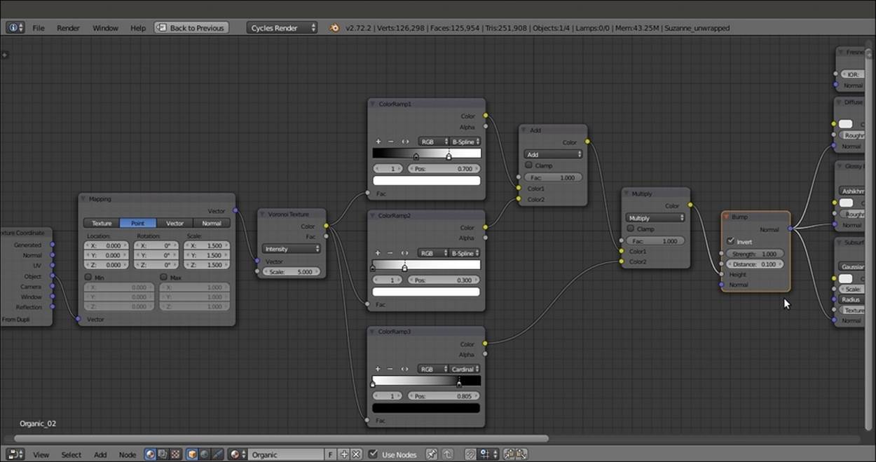
The Bump node
14. Now, box-select (press the B key) the Texture Coordinate node and the Mapping nodes, and move them to the left to make room for new nodes.
15. Add a MixRGB node (press Shift + A and navigate to Color | MixRGB) and label it as Vector_deform. Paste it between the Mapping and Voronoi Texture nodes.
16. Add a Noise Texture node (press Shift + A and navigate to Texture | Noise Texture), connect to its Vector input socket the Mapping node output, and set the Scale value to 7.200. Connect the Noise Texture node's Color output to the Color2 input socket of the Vector_deform node. Set the Fac value of the Vector_deform node to 0.080, as shown in the following screenshot:
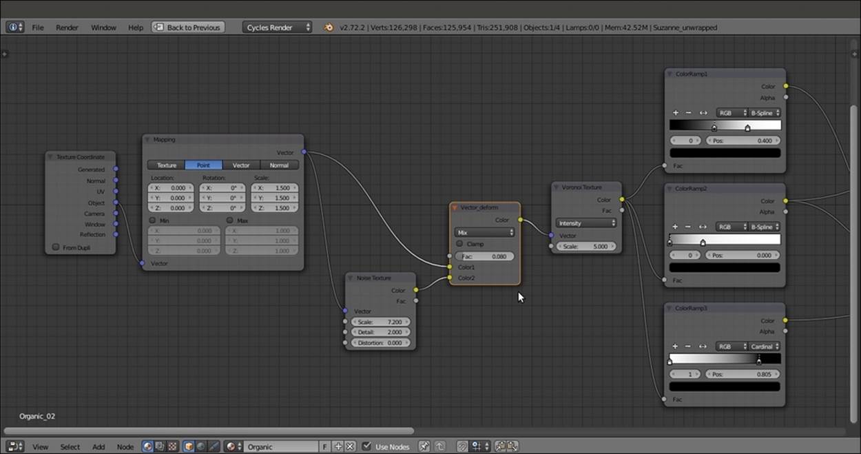
Deforming the mapping coordinates of the bump textures through a procedural noise
17. Add an RGB node (press Shift + A and navigate to Input | RGB) and a new MixRGB node (press Shift + A and navigate to Color | MixRGB). Label the MixRGB node
18. as Color_Diffuse.
19. Press Shift + D to duplicate the Color_Diffuse node and label the duplicate as Color_Glossy.
20. Connect the Color_Diffuse node's output to the Color input socket of the Diffuse BSDF shader node, and the Color_Glossy node's output to the Color input socket of the Glossy BSDF shader node.
21. Connect the output of the RGB node to the Color1 input sockets of both the Color_Diffuse and Color_Glossy nodes. Connect the RGB node also to the Color input socket of the Subsurface Scattering node.
22. Press Shift + D to duplicate the Color_Diffuse node, set Blend Type of the duplicate to Multiply, and label it as Multiply_Diffuse; then, paste it between the Color_Diffuse and Diffuse BSDF shader nodes.
23. Connect the Color output of the ColorRamp2 node to the Color2 input socket of the Multiply_Diffuse node. Set the Fac value of this to 0.770.
24. Go to the Color_Diffuse node and set the Fac value to 0.830, and change the Color2 value of R to 0.315, G to 0.500, and B to 0.130.
25. Go to the Color_Glossy node and set the Fac value to 0.770, and change the Color2 values of R to 0.860, G to 0.611, and B to 0.203.
26. Go to the RGB node and set the Color values for R to 0.900, G to 0.123, and B to 0.395, as shown in the following screenshot:
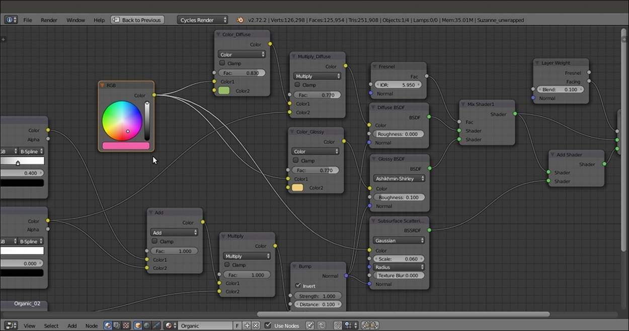
Adding the color nodes
27. Save the file as 9931OS_organic.blend.
How it works...
· From step 1 to 7, we built a shader that is very similar to the shaders that we have already seen for SSS_materials.
· From step 8 to 13, we built the bump pattern by using a single Voronoi Texture node tuned through three ColorRamp nodes with different settings.
· From step 14 to 16, we added, through the very low value of a MixRGB node, the values of a Noise Texture node to the vector of the Voronoi Texture node to obtain a less regular pattern.
· From step 17 to 25, we built the color pattern by establishing a base color by the RGB node and introducing a variation through the MixRGB nodes connected to the Color input sockets of the shader components. Note that the base pink color set in the RGBnode goes straight to the SSS node. The MixRGB varied greenish color is multiplied by one of the bump outputs and then goes to the diffuse component of the shader, while the varied yellowish color is for the glossy component instead.
Creating a wasp-like chitin material with procedural textures
In this recipe, we will create a material similar to chitin (the characteristic substance of the exoskeletons of insects) colored with a yellow and black pattern like a wasp, as shown in the following screenshot:
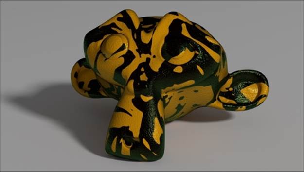
The insect wasp-like material as it appears in the final rendering
Getting ready
Start Blender and open the 9931OS_08_start.blend file, where there is an already set scene with an unwrapped Suzanne primitive object leaning on a Plane, an Emitter mesh-light, and a Camera.
Go to the World window and enable the Ambient Occlusion item with the Factor value 0.10.
How to do it...
Let's start immediately with the material creation using the following steps:
1. Click on the New button in the Node Editor window toolbar or in the Material window under the main Properties panel to the right, and rename the new material chitin_wasp.
2. Now, in the Material window, switch the Diffuse BSDF shader with a Mix Shader node, and label it as Mix Shader2. In the first Shader slot, select a new Mix Shader node. In the second one, select a Glossy BSDF shader node. Label the new Mix Shadernode as Mix Shader1, and the Glossy BSDF node as Glossy BSDF_2.
3. Go to the Mix Shader1 node, and in the first Shader slot, select a Diffuse BSDF shader, and in the second one, select a new Glossy BSDF shader node. Label the latter as Glossy BSDF_1, and set its Roughness value to 0.100 and Distribution to Beckmann, and change the Color value for R to 0.039, G to 0.138, and B to 0.046.
4. Set the Glossy BSDF_2 node's Roughness value to 0.040 and Distribution to Beckmann, and change its Color values for R to 0.500, G to 0.440, and B to 0.086. Set the Fac value of the Mix Shader2 node to 0.025.
5. Add a Layer Weight node (press Shift + A and navigate to Input | Layer Weight) and connect its Facing output to the Fac input socket of the Mix Shader1 node. Leave the Blend value as 0.500, as shown in the following screenshot:
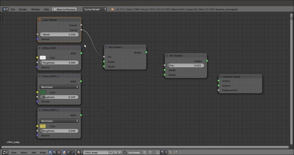
The nodes for the base shader
6. Add a Texture Coordinate node (press Shift + A and navigate to Input | Texture Coordinate) and a Mapping node (press Shift + A and navigate to Vector | Mapping). Connect the UV output of the Texture Coordinate node to the Vector input of theMapping node. Label the latter as Mapping1.
7. Add a Voronoi Texture node (press Shift + A and navigate to Texture | Voronoi Texture) and a Noise Texture node (press Shift + A and navigate to Texture | Noise Texture). Connect the Mapping1 node's Vector output to their Vector input sockets. Set the Scale values of both the texture nodes to 300.000 and then label the Noise Texture node as Noise Texture1.
8. Add a Bump node (press Shift + A and navigate to Vector | Bump) and connect the Color output of the Voronoi Texture node to the Height input socket of the Bump node. Connect the Normal output of this node to the Normal input sockets of the Diffuse BSDF node and both Glossy BSDF shader nodes. Set the Bump node's Strength value to 0.500.
9. Add a ColorRamp node (press Shift + A and navigate to Converter | ColorRamp), label it as ColorRamp1, and paste it between the Voronoi Texture node and the Bump node. Set Interpolation to Ease and move the white color stop to the 0.059 position.
10. Add a Math node (press Shift + A and navigate to Converter | Math), set Operation to Multiply, and connect the Fac output of the Noise Texture1 node to the first Value input socket of the Math node. Set the second Value to 0.100 and connect the Valueoutput to the Displacement input socket of the Material Output node, as shown in the following screenshot:
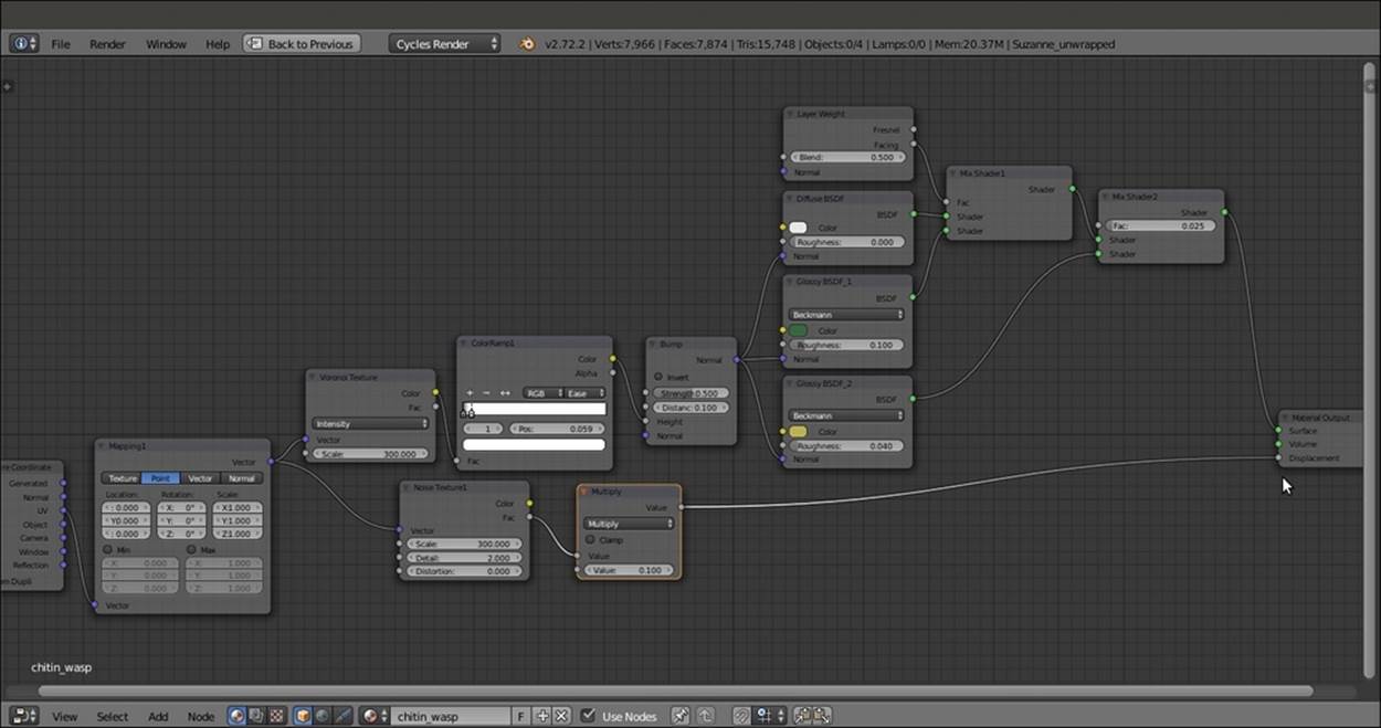
Textures connected either as per the shader bump and the total bump to the Displacement input socket of the Material Output node
11. Add a new Mapping node (press Shift + A and navigate to Vector | Mapping), label it as Mapping2, and connect the UV output of the Texture Coordinate node to its Vector input socket. Set the Rotation value for Y to 90° and the Rotation value of Z to 45°. Set the Scale value for all three axes to 5.000.
12. Add a Noise Texture node (press Shift + A and navigate to Texture | Noise Texture) and a ColorRamp node (press Shift + A and navigate to Converter | ColorRamp). Label them as Noise Texture2 and ColorRamp2.
13. Connect the output of the Mapping2 node to the Vector input socket of the Noise Texture2 node, and the Fac output of this node to the Fac input socket of ColorRamp2. Connect the output of this node to the Color input socket of the Diffuse BSDF shader node.
14. Go to the Noise Texture2 node and set the Scale and Distortion values to 2.000. Go to the ColorRamp2 node and set Interpolation to Constant, select the white color stop, and change the Color values for R to 1.000, G to 0.429, and B to 0.000.
15. Click on the + icon button to add new color stops until you have eight color stops almost evenly spaced along the slider (that is: color stop 0 at the 0.000 position, 1 at the 0.125 position, 2 at the 0.250 position, then 0.357, 0.491, 0.626, 0.745, and 0.886).
16. Select the last color stop, put the mouse pointer on the color slider, and press Ctrl + C to copy the yellow color; then, select the color stops numbered 1, 3, and 5, and paste the color (press Ctrl + V) so as to have a slider subdivided in eight parts, four black and four yellow, as shown in the following screenshot:
The color pattern connected to the diffuse component
How it works...
· From step 1 to 5, we built the basic shader using two Glossy BSDF shaders with different colors to mimic a color shifting in the specularity areas.
· From step 6 to 10, we built the chitin bump, assigning the pores to the per-shader bump but a general noise pattern to the displacement output (which, in this case, still works as a simple bump).
· From step 11 to 16, we built a simple and random wasp-colored pattern; obviously, this can be changed and modified as you prefer, and actually should also be used on a more appropriate model; in this case, it would be better to make use of a painted color texture map to build a more appropriate and symmetrical color pattern.
Creating a beetle-like chitin material with procedural textures
In this recipe, we will create a material similar to iridescent chitin (found in some kinds of beetles), as shown in the following screenshot:
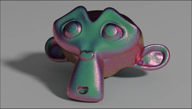
The beetle chitin-like material as it appears in the final rendering
Getting ready
Start Blender and open the 9931OS_08_start.blend file, where there is an already set scene with an unwrapped Suzanne primitive object leaning on a Plane, an Emitter mesh-light, and a Camera.
Go to the World window and enable the Ambient Occlusion option with the Factor value as 0.10.
How to do it...
Let's start immediately with the material creation using the following steps:
1. Click on the New button in the Node Editor window's toolbar or in the Material window under the main Properties panel to the right, and rename the new material as chitin_beetle.
2. Now, in the Material window, switch the Diffuse BSDF shader with a Mix Shader node and label it as Mix Shader2. In the first Shader slot, select a new Mix Shader node; in the second Mix Shader node, select a Glossy BSDF shader node. Label the newMix Shader node as Mix Shader1, and the Glossy BSDF one as Glossy BSDF_2.
3. Go to the Mix Shader1 node, and in the first Shader slot, select a Diffuse BSDF shader, and in the second one, select a new Glossy BSDF shader node; label this node as Glossy BSDF_1 and set its Roughness value to 0.200 and Distribution to Beckmann, and change the Color values for R to 1.000, G to 0.000, and B to 0.562.
4. Set the Glossy BSDF_2 node's Roughness value to 0.100 and Distribution to Beckmann, and change its Color values for R to 0.800, G to 0.574, and B to 0.233.
5. Add a Layer Weight node (press Shift + A and navigate to Input | Layer Weight), label it as Layer Weight1, and connect its Facing output to the Fac input socket of the Mix Shader2 node. Leave the Blend value at 0.500.
6. Add a second Layer Weight node (press Shift + A and navigate to Input | Layer Weight), label it as Layer Weight2, and connect its Facing output to the Fac input socket of the Mix Shader1 node. Leave the Blend value at 0.800, as shown in the following screenshot:
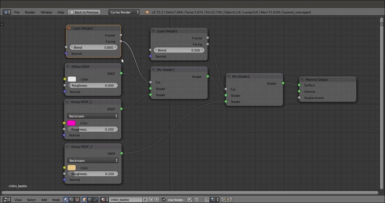
The shader part of the material
7. Add a Texture Coordinate node (press Shift + A and navigate to Input | Texture Coordinate) and a Mapping node (press Shift + A and navigate to Vector | Mapping). Connect the UV output of the Texture Coordinate node to the Vector input of theMapping node.
8. Add a Voronoi Texture node (press Shift + A and navigate to Texture | Voronoi Texture) and a Noise Texture node (press Shift + A and navigate to Texture | Noise Texture); connect the Mapping output to their Vector input sockets. Set the Scale values of both the texture nodes to 300.000.
9. Add a Bump node (press Shift + A and navigate to Vector | Bump) and connect the Color output of the Voronoi Texture node to the Height input socket of the Bump node; connect the Normal output of this node to the Normal input sockets of Diffuse BSDF and of both the Glossy BSDF shader nodes. Set the Bump node's Strength value to 0.500.
10. Add a ColorRamp node (press Shift + A and navigate to Converter | ColorRamp) and paste it between the Voronoi Texture node and the Bump node. Set Interpolation to Ease and move the white color stop to the 0.059 position.
11. Add a Math node (press Shift + A and navigate to Converter | Math), set Operation to Multiply, and label it as Multiply1; connect the Fac output of the Noise Texture node to the first Value input socket of the Math node. Set the second Value to 0.075 and connect the Value output to the Displacement input socket of the Material Output node, as shown in the following screenshot:
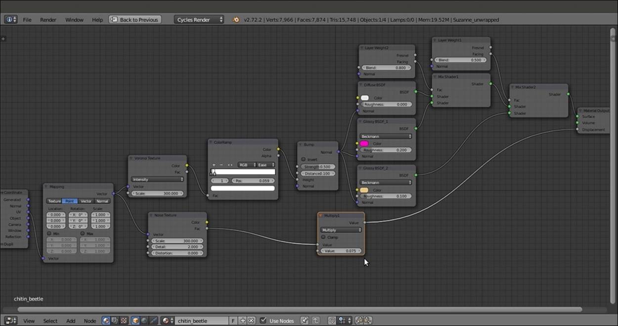
The bump is both "per shader" and as "total" bump (as in the previous wasp material recipe)
12. Add a new Layer Weight node (press Shift + A and navigate to Input | Layer Weight), two Math nodes (press Shift + A and navigate to Converter | Math), and a Hue Saturation Value node (press Shift + A and navigate to Color | Hue/Saturation); label the new Layer Weight node as Layer Weight3.
13. Connect the Facing output of the Layer Weight3 node to the first Value input socket of one of the Math nodes; set its Operation to Multiply and the second Value to 0.700, and label it as Multiply2.
14. Connect the Multiply2 node's output to the first Value input socket of the second Math node, and the output of this node to the Hue input socket of the Hue Saturation Value node; connect the output of this node to the Color input socket of the Diffuse BSDFshader node.
15. Change the Hue Saturation Value node's Color values for R to 0.103, G to 0.500, and B to 0.229, and just for this example, leave the other values as they are, as shown in the following screenshot:
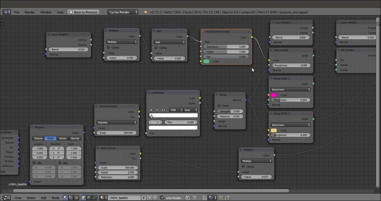
Adding the final diffuse color
How it works...
· The introductory steps of this shader work almost the same as for the chitin_wasp material, that is, the basic shader from step 1 to 6 and the chitin bump from step 7 to 11.
· From step 12 to 15, we build the color component coming from the Hue Saturation Value node, and thanks to the combination of the Layer Weight3 and Math nodes, this appears mainly in the mesh faces perpendicular to the point of view, sliding in the other spectrum colors on the facing-away mesh sides, basically behaving as a sort of Fresnel effect. The addition of the Hue Saturation Value node allows for further color tweaking.
Creating tree shaders – the bark
There are several different ways to make trees in a 3D package: starting from the simpler low-poly objects, such as the billboards used in video games (simple planes mapped with tree images on a transparent background), to middle complex objects where a trunk mesh is attached to a foliage mass made of little alpha textured planes, each one representing a leaf or even a twig, to more complex and heavy meshes, where every little branch and leaf is actually modeled.
In case you need them, you can find several free tree models in the Blender format and also their billboard versions at http://yorik.uncreated.net/greenhouse.html.
For this two-part tree shader recipe, we will instead use a model coming from the many environment assets of the CG short Big Buck Bunny, the second open movie produced by the Blender Foundation. All the movie assets are free to be downloaded, distributed, and reused even for commercial projects because the short is licensed under the Creative Commons Attribution 3.0 license (refer to its official website at http://creativecommons.org/licenses/by/3.0/).
The general shape of the tree and the leaves is pretty toyish. This is because they are elements that have been drawn to match the toon style of the furry characters, but it's actually perfectly suited for our demonstration purposes. The final rendered tree from Big Buck Bunny is shown in the following screenshot for your reference:
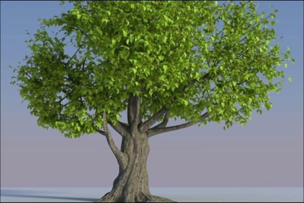
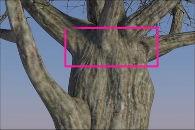
The final rendered tree from Big Buck Bunny
The tree model is composed of several parts: on the first layer, there are the tree_trunk, the tree_branch, and the tree_branches meshes, and on the second layer are the leaves, made by a single leaf object dupliverted on the tiny faces of the leaves_dupliobject. (That is, the leaf_tobeswitched object is parented to the leaves_dupli object, and then, in the Object window and under the Duplication subpanel, the Faces duplication method has been selected, the Scale item checked, and the Inherit Scale value set to 1110.000. This way, the leaf_tobeswitched object is instanced on the leaves_dupli object's many faces according to their location, rotation, and scale.)
On the 11th layer, there are three leaf objects with three different levels of detail: a simple flat Plane, a subdivided and curved Plane, and a modeled leaf. Their presence is only to supply the low, middle, and high resolution mesh data. By selecting theleaf_tobeswitched object and by going to the Object data window, it is possible to switch between the leaf_generic_low, leaf_generic_mid, and leaf_generic_hi foliage levels of detail.
In the first part of this two-part recipe, we will create the material for the bark, as shown in the following screenshot:
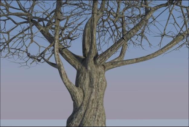
The bark material
Getting ready
Start Blender and open the 9931OS_08_tree_start.blend file. For this recipe, deactivate the second layer, and in Outliner, select the tree_trunk object.
How to do it...
Let's start by creating the bark material using the following steps:
1. Click on the New button in the Node Editor window toolbar or in the Material window, and rename the material as bark.
2. Still in the Material window, switch the Diffuse BSDF shader with a Mix Shader node, and label it as Mix Shader_bark1. In the first Shader slot, select a Diffuse BSDF shader node, and in the second one, select a Glossy BSDF shader node; then, label them as Diffuse_bark1 and Glossy_bark1. Set the Glossy_bark distribution to Beckmann, the Roughness value to 0.800, and the Mix Shader_bark1 node's Fac value to 0.200.
3. Add a Texture Coordinate node (press Shift + A and navigate to Input | Texture Coordinate), a Mapping node (press Shift + A and navigate to Vector | Mapping), and an Image Texture node (press Shift + A and navigate to Texture | Image Texture); label the last two as Mapping1 and Bark_color1.
4. Connect the UV output of the Texture Coordinate node to the Vector input socket of the Mapping1 node, and the output of this node to the Vector input socket of the Bark_color1 node. Connect the Color output of the Bark_color1 node to the Color input sockets of both the Diffuse_bark1 and Glossy_bark1 shader nodes.
5. Click on the Open button of the Bark_color1 node, browse to the textures folder, and load the bark_color_tile.png image.
6. Press Shift + D to duplicate the Bark_color1 node, label it as Bark_normal1, and connect the Mapping1 node output to its Vector input socket. Make the image datablock single-user by clicking on 2, which appears on the right side of the image name. Click on the Open Image button (the one with the folder icon), browse again to the textures folder, and load the bark_norm_tile.png image. Set Color Space to Non-Color Data.
7. Add a Normal Map node (press Shift + A and navigate to Vector | Normal Map), label it as Normal Map1, and connect the Color output of the Bark_normal1 node to the Color input socket of the Normal Map1 node, and then set the Strength value to 2.000. Click on the UV Map for tangent space maps button upwards of the Strength one and select UVMap (the trunk mesh has two different sets of UV coordinates, which we'll see later).
8. Connect the Normal output of the Normal Map1 node to the Normal input sockets of both the Diffuse_bark1 and the Glossy_bark1 shader nodes, as shown in the following screenshot:
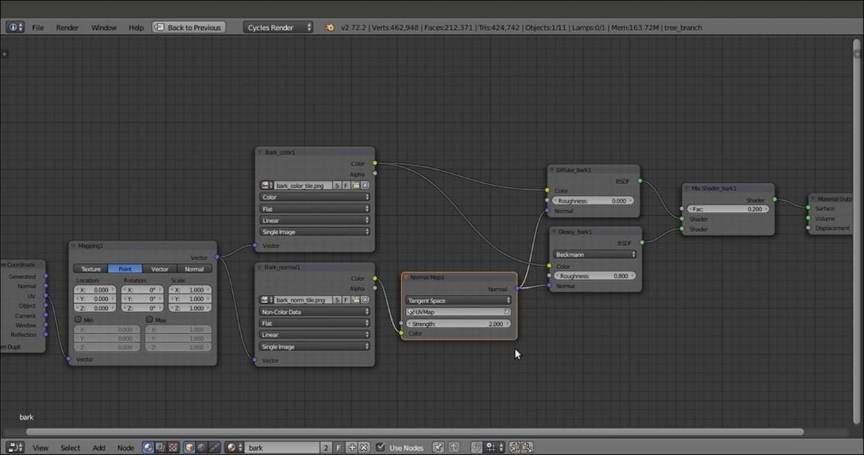
The basic bark material that uses a normal map
9. Now, box-select (press the B key and then draw a rectangle) all the nodes except for the Texture Coordinate and Material Output nodes and press Shift + D duplicate them. Move them down and change their labels by substituting the 1 suffix with 2. Connect the UV output of the Texture Coordinate node to the Vector input socket of the duplicated Mapping2 node, and set the Scale of this node to 0.350 for all three axes.
10. Add a Mix Shader node (press Shift + A and navigate to Shader | Mix Shader), label it as Mix Shader_bark3, and paste it right before the Material Output node. Connect the output of the Mix Shader_bark2 node to the second Shader input socket of the Mix Shader_bark3 node.
11. Add a Noise Texture node (press Shift + A and navigate to Texture | Noise Texture), connect the UV output of the Texture Coordinate node to the Vector input socket of the Noise Texture node, and connect the Fac output of this node to the Fac input socket of the Mix Shader_bark3 node.
12. Set the Noise Texture node's Scale value to 15.000, as shown in the following screenshot:
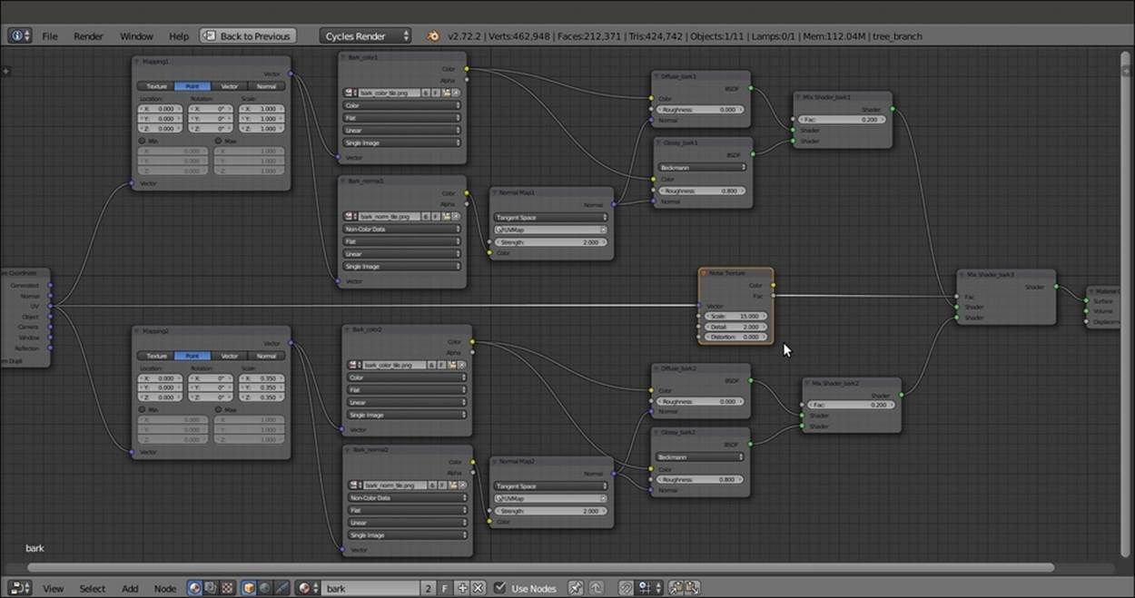
Making the bark material a bit more complex
13. Now, press Shift and select the tree_branch and tree_branches meshes, and as the last one, reselect the tree_trunk mesh to make it the active object; then, press Ctrl + L. In the Make Links pop-up menu, select the Materials item to assign the bark material to the other two meshes.
How it works...
· For this material, we built a simple shader using two tileable image maps, a color one for the Diffuse and the Glossy components, and a normal map for the bump.
· Then, we duplicated everything and mixed the second material copy with different scale values to the first one by the factor of a Noise procedural texture, to add variety to the bark pattern and to avoid that unpleasant repeating effect that often shows up with tileable image textures.
There's more...
At this point, if you look carefully at the Rendered view of the tree trunk, you'll see that sadly, there are ugly seams where the trunk's main body joins the big low branches as shown in the following screenshot:
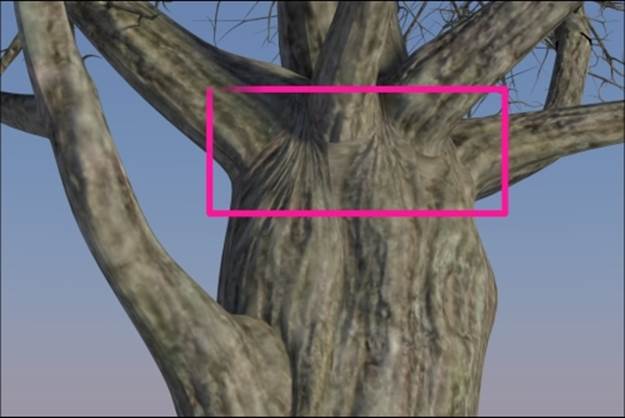
The visible seams at the branches joining
This is due to the fact that the unwrap of the mesh has separated the branches' UV islands from the main trunk ones. Although the effect can be barely visible, let's say that you absolutely want to avoid this; that's why we are now going to see a solution for the problem, by using a second set of UV coordinates and a Vertex Color layer.
This is what we are going to do:
1. Select the trunk mesh and go into the Vertex Paint mode; the mesh turns totally white, because that is the color assigned to the vertexes by default. Start to paint with pure black on the vertexes located at the joining of the low branches with the trunk, achieving this result:
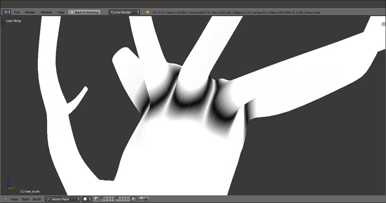
The trunk model seen in the Vertex Paint mode
2. As you can see, the joining vertices edge loops are black but are smoothly blending into the white of the default mesh vertex color. This will be used as a stencil map to blend two different instances of the same bark material mapped on different UV coordinates. Go to the Object data window and rename the Vertex Color layer as Join_branches.
3. Switch to Edit Mode and select all the faces including the necessary vertices' edge loops; in the Object data window, under the UV Maps subpanel, click on the + icon (add UV Map) and rename the new UV coordinates layer as UVMap2. Place the mouse cursor on the 3D viewport, press U, and select Unwrap in the UV Mapping pop-up menu, as shown in the following screenshot:
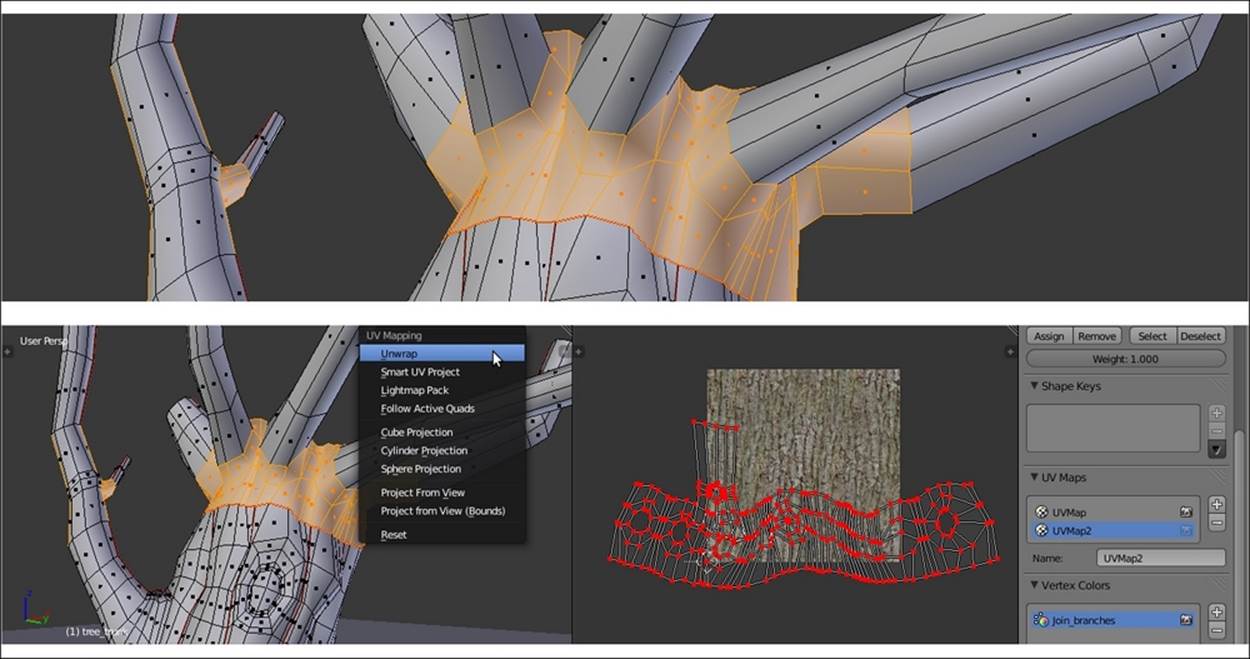
The trunk model in Edit Mode and the UV islands in the UV/Image Editor window
4. Go out of Edit Mode. Click on the user number to the right of the material data block in the Node Editor window toolbar and rename the new material as bark_seamless.
Now, by looking at the following screenshot, it is clear what we have to do:
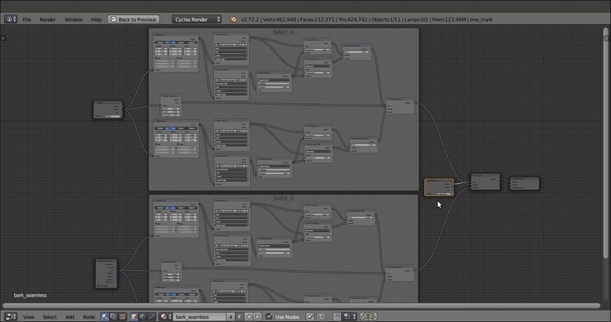
Two identical bark materials mapped on different UV layers and mixed on the ground of the Vertex Paint output
5. Make a duplicate of the bark material and blend the two shaders (inside the BARK_A and BARK_B frames respectively) using a Mix Shader node, modulated by the Join_branches vertex color stencil. Use an Attribute node both for the Vertex Color layer output and to set the UVMap2 coordinates layer for the copy of the bark material. Now, the output looks similar to what is shown in the following screenshot:
The final result: no more seams
As you can see in the preceding screenshot, there are no more visible seams; the two differently UV mapped materials smoothly blend together.
Creating tree shaders – the leaves
In this second tree recipe, we will create the leaves shaders, as shown in the following screenshot:
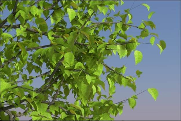
The leaves as they appear in the final rendering
Getting ready
Carrying on with the blend file of the previous recipe, now, activate (hold Shift while clicking) the 2nd and the 11th scene layers, and in Outliner, select the leaf_generic_mid object.
How to do it...
Let's proceed with the creation of the leaves shaders:
1. Click on the New button in the Node Editor window toolbar or in the Material window, and rename the material as leaf_alpha.
2. In the Material window, switch the Diffuse BSDF shader with a Mix Shader node and label it as Mix Shader Cutout; in the first Shader slot, select a Transparent BSDF shader node, and in the second one, select a new Mix Shader node, which will be labeled as Mix Shader Add Translucency.
3. Add an Image Texture node (press Shift + A and navigate to Texture | Image Texture), label it as MASK, and connect its Alpha output to the Fac input socket of the Mix Shader Cutout node.
4. Click on the Open button of the MASK node, browse to the textures folder, and load the leaf_generic_mask.png image (which actually is a simple black leaf silhouette with a transparent alpha channel). Set Color Space to Non-Color Data.
5. Add a Diffuse BSDF node (press Shift + A and navigate to Shader | Diffuse BSDF), a Glossy BSDF node (press Shift + A and navigate to Shader | Glossy BSDF), and a Translucent BSDF node (press Shift + A and navigate to Shader | Translucent BSDF).
6. Add two new Mix Shader nodes (press Shift + A and navigate to Shader | Mix Shader), and label them as Mix Shader1 and Mix Shader2.
7. Connect the output of the Diffuse BSDF shader to the first Shader input socket of the Mix Shader1 node, and the output of the Glossy BSDF shader to the second Shader input socket. Set the Glossy BSDF node's Distribution to Beckmann, and change the Color values for R to 0.794, G to 0.800, and B to 0.413, and the Roughness value to 0.500.
8. Connect the output of the Mix Shader1 node to the first Shader input socket of the Mix Shader2 node, and the output of the Translucent node to the second one; connect the output of the Mix Shader2 node to the second Shader input socket of the Mix Shader Add Translucency node.
9. Connect the output of the Diffuse BSDF shader node to the first Shader input socket of the Mix Shader Add Translucency node. Set its Fac value to 0.300 (this value establishes the amount of translucency in the shader).
10. Add an Image Texture node (press Shift + A and navigate to Texture | Image Texture), label it as TRANSLUCENCY, and connect its Color output to the Fac input socket of the Mix Shader2 node. Click on the Open button, browse to the usual textures folder, and load the leaf_generic_trans.png image. Set Color Space to Non-Color Data.
11. Add a Fresnel node (press Shift + A and navigate to Input | Fresnel), connect it to the Fac input socket of the Mix Shader1 node, and set IOR to 1.500.
12. Add an Image Texture node (press Shift + A and navigate to Texture | Image Texture), label it as COLOR, and connect its Color output to the Color input socket of the Diffuse BSDF shader node and to the Color input socket of the Translucent BSDF node. Click on the Open button, browse to the textures folder, and load the leaf_generic_col.png image.
13. Add a Hue Saturation Value node (press Shift + A and navigate to Color | Hue/Saturation) and paste it between the COLOR image texture node and the Translucent BSDF shader node. Set the Hue value to 0.350 and Value to 2.000.
14. Add a last Image Texture node (press Shift + A and navigate to Texture | Image Texture) and label it as BUMP; add a Bump node (press Shift + A and navigate to Vector | Bump) and connect the BUMP image node's Color output to the Height input socket of the Bump node, and the Normal output socket of this node to the Normal input sockets of the Diffuse BSDF, Glossy BSDF, and Translucent BSDF shader nodes.
15. Click on the Open button, browse to the textures folder, and load the leaf_generic_bump.png image. Set Color Space to Non-Color Data and the Bump node's Strength value to 0.200, as shown in the following screenshot:
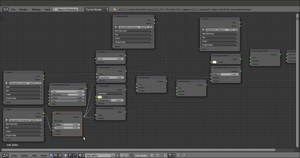
The leaf_alpha material network
How it works...
· From step 1 to 11, we built the basic shader of the leaf, using an image that has alpha channel data to cut out the leaf shape on the Plane and a gray-scale image to drive the translucency effect.
· From step 12 to 15, we added the color of the leaf, using it also with a hue and intensity variation for the translucency color, and then we added the bump.
There's more...
Now, assign the same material to both the leaf_generic_low and leaf_generic_hi meshes on the 11th layer.
The modeled leaf mesh doesn't need the alpha channel, so select the leaf_generic_hi object, and in the toolbar of the Node Editor window, click on user data number to make it single-user. Rename the new material as leaf and delete the MASK andTransparent BSDF nodes, and then press Alt + D to remove the Mix Shader Cutout node from the link and delete it as well.
Remember that the examples in the preceding and following images are made with very stylized models that come from the Big Buck Bunny short movie; real objects have more subtle details and more random repeating patterns, but in this case, this just depends on the image textures you are going to use for your material.
Such a shader is of good use not only for leaves, but also for other kinds of plants; in many cases, it's enough to give variations to the color.
Creating a layered human skin material in Cycles
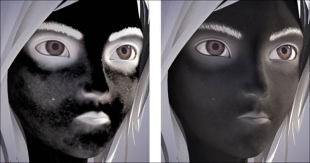
In this recipe, we will create a layered skin material by using the open-content character Sintel.
Sintel is the main character of the third open movie of the same name produced by the Blender Foundation; the Sintel character and all the other movie assets are licensed under the Creative Commons Attribution 3.0 license (http://creativecommons.org/licenses/by/3.0/). The following screenshot is of Sintel's face:
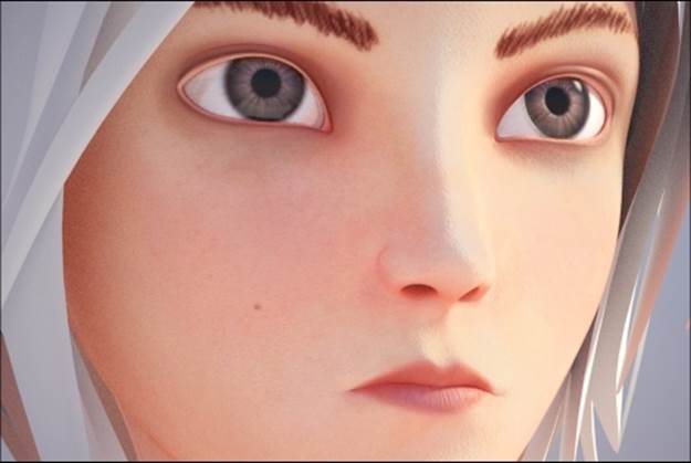
Sintel's face in the final rendering
Getting ready
Start Blender and open the 9931OS_08_skin_start.blend file, where there is an already set scene with the Sintel character standing on a Plane, a Sun lamp, and a Camera.
Except for Sintel's body skin, all the other mesh objects have either gesso-like materials or eyes already assigned.
How to do it...
Let's start with the layered skin shader creation:
1. Be sure to have the Sintel object selected, and then click on the New button in the Node Editor window toolbar or in the Material window under the main Properties panel and rename the material as skin_layered.
2. In the Material window, switch the Diffuse BSDF shader with a Mix Shader node; go to the Active Node panel to the right of the Node Editor window (if not present, put the mouse in the Node Editor window and press N to make it appear), and in the Labelslot, rename the Mix Shader as Mix Shader1.
3. In the first Shader slot of this new Mix Shader1 node, select a Diffuse BSDF shader node, and in the second one, select an Add Shader node; label this node as Add SPEC.
4. Add two Glossy BSDF shader nodes (press Shift + A and navigate to Shader | Glossy BSDF) and label them as Glossy BSDF_1 and Glossy BSDF_2. Set their Distribution to Ashikhmin-Shirley, and then connect their output to the first and second Shader input sockets of the Add SPEC node respectively.
5. Add a Fresnel node (press Shift + A and navigate to Input | Fresnel) and connect it to the Fac input socket of the Mix Shader1 node. Set IOR to 1.450.
6. Press Shift + D to duplicate the Mix Shader1 node, label the duplicate as Mix Shader2, and paste it between the Mix Shader1 and the Material Output nodes.
7. Press Shift + D to duplicate the Add SPEC node, label the duplicate as Add SSS, and connect its output to the first Shader input socket of the Mix Shader2 node, so that the connection that comes from the Mix Shader1 node automatically switches to the second Shader input socket. Connect the output of the Mix Shader1 node also to the second Shader input socket of the Add SSS node.
8. Add a Subsurface Scattering node (press Shift + A and navigate to Shader | Subsurface Scattering) and connect its output to the first Shader input socket of the Add SSS node. Set Falloff to Gaussian; Scale to 0.050; Radius to 4.000, 2.000, and 1.000; and the Texture Blur value to 0.100, as shown in the following screenshot:
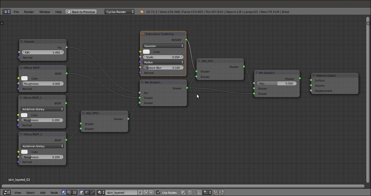
The basic shader
9. Add an Image Texture node (press Shift + A and navigate to Texture | Image Texture) and label it as EPIDERMIS; connect its Color output to the Color input sockets of the Diffuse BSDF and Subsurface Scattering nodes and the two Glossy BSDF nodes.
10. Click on the Open button of the EPIDERMIS image texture node, browse to the textures folder, and load the sintel_skin_diff.png image.
11. Add two ColorRamp nodes (press Shift + A and navigate to Converter | ColorRamp) and label them as ColorRamp_Spec1 and ColorRamp_Spec2. Connect the Color output of the EPIDERMIS node also to the Fac input socket of both the ColorRamp nodes.
12. Connect the Color output of the ColorRamp_spec1 node to the Roughness input socket of the Glossy BSDF_1 shader node; set Interpolation to Ease, and move the black color stop to the 0.550 position and the white color stop to the 0.000 position.
13. Connect the Color output of the ColorRamp_spec2 node to the Roughness input socket of the Glossy BSDF_2 shader node; set Interpolation to B-Spline, and move the white color stop to the 0.100 position and the white color stop to the 0.000 position, as shown in the following screenshot:
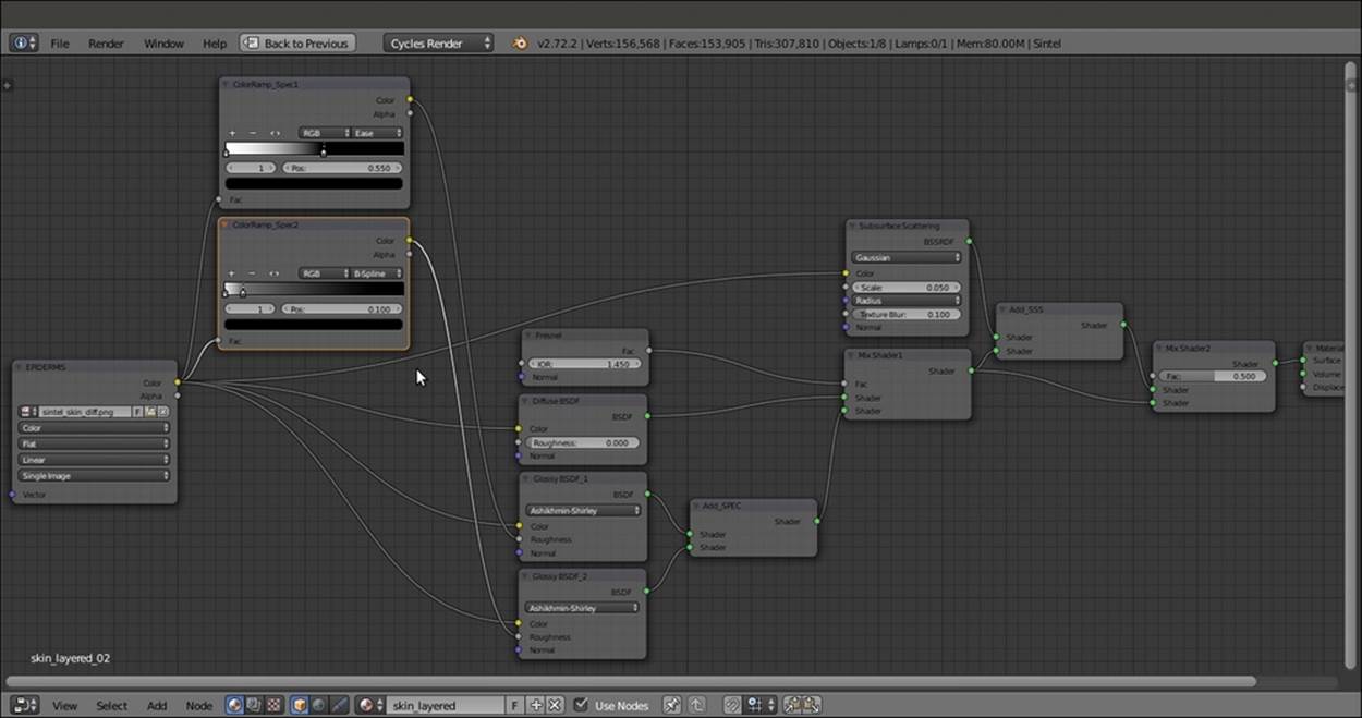
Sintel's color map is directly connected to the shader nodes but is modulated through ColorRamp nodes for the roughness of the glossy nodes
14. Add a Hue Saturation Value node (press Shift + A and navigate to Color | Hue/Saturation), label it as Hue Saturation Value DERMIS, and paste it between the EPIDERMIS and Subsurface Scattering nodes. Set the Hue value to 0.470, the Saturation value to1.500, and Value to 1.200.
15. Add a new Image Texture node (press Shift + A and navigate to Texture | Image Texture) and a Bump node (press Shift + A and navigate to Vector | Bump); label this Image Texture node as BUMP, and connect its Color output to the Height input socket of the Bump node, and the Normal output of this node to the Normal input sockets of the Diffuse BSDF node, of the two Glossy BSDF nodes, and of the Subsurface Scattering nodes.
16. Click on the Open button of the BUMP image texture node, browse to the textures folder, and load the sintel_skin_bmp.png image. Set Color Space to Non-Color Data and the Bump node's Strength value to 0.100, as shown in the following screenshot:
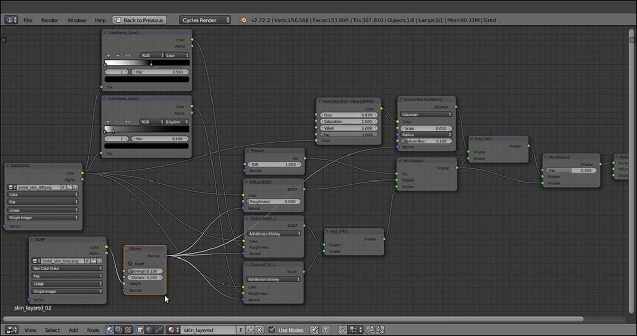
The same color map modified for the SSS node and the bump map connected as per the shader bump
How it works...
In this recipe, we used a layered approach to build the human skin shader, but what does layered mean exactly?
It means that the shader tries to simulate the behavior of real human skin in the most effective possible way. I'm referring to the fact that the human skin is composed of several different overlapping and semi-transparent layers that reflect and absorb light rays in various ways, giving the reddish coloration to certain areas due to the famous subsurface scattering effect.
Now, a perfect reproduction of the real human skin model is not necessary; usually, it's enough to use different image maps for the key components of the shader, each one added on top of the other: the base color, the dermis blood layer, the specularity map, and the bump map.
In our case, we had at our disposal only two image maps, the sintel_skin_diff.png color one and the sintel_skin_bmp.png gray-scale map, which we used straight for the bump; we could have obtained the missing maps with the aid of an image editor (such as, for example, GIMP), but for the sake of this exercise, to obtain the required missing images, we used the nodes: so, starting from the EPIDERMIS layer, that is the color map, we obtained via the Hue Saturation Value DERMIS node the blood-vessel layer that lies beneath the epidermis, as shown in the following screenshot:
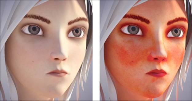
The normal color map and the blood-vessel version rendered separately
By the use of the two ColorRamp nodes and the two gray-scale versions for the specularity component, one sharp specularity map and a softer one are shown in the following screenshot:
The two different glossy maps obtained from the same color map and rendered separately
Then, the sintel_skin_bmp.png map has been connected to the Bump node for the per-shader bump effect.
Note that because we used the color map to obtain all the others, certain areas of the images are wrong; for example, the eyebrows, shown in pure white on the specularity maps, should have been removed. In any case, this doesn't show that much on the final render, and the result is more than acceptable.
Creating fur and hair
Fur, in the world of computer graphics, is considered among the most difficult things to recreate, both because it's generally quite expensive from a memory management point of view (a single character can easily have millions of hair strands) and also because it can be quite a task to make a believable shader that can work under different light conditions.
Blender is not new to fur creation; the exact goal of the open movie Big Buck Bunny was to add tools for fur creation to the Blender Internal rendering engine, and it did it through a new type of primitive, strands, which have to be enabled in the Particle panel (theStrand render item); strands are very instanced on the particle system, but they can be edited, combed, and tweaked in several ways to obtain the best possible result.
Almost the same concept applies for the Cycles rendering engine; there's no need to enable the Strand render item anymore, because strands are rendered automatically by Cycles when the Hair item is selected as Particle Type.
In fact, once the Hair item's Particle Type has been selected, you will find two more subpanels at the bottom of the Particle window: Cycles Hair Rendering and Cycles Hair Settings. Here is a screenshot of the teddy bear Suzanne in the Rendered view:
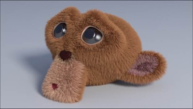
The Rendered teddy bear Suzanne
Getting ready
Start Blender and open the 9931OS_08_hair_start.blend file; in the scene, there is a Suzanne primitive (Suzanne_teddybear) with a Hair particle system already named teddybear and set (go to see it in the Particle window) to resemble the fur of a cuddly toy.
The Suzanne_teddybear mesh is already unwrapped and has a Vertex Group named density, used in the Particle window (the Vertex Groups subpanel) to establish the Density distribution of the fur on the mesh (in short, to avoid fur on the eyes, the nose, and inside the mouth) as shown in the following screenshot:
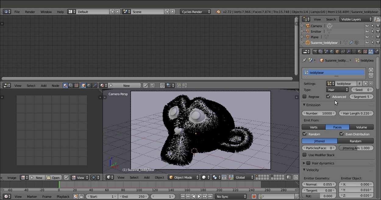
A screenshot of the particle system as it appears in the Solid viewport shading mode and the settings to the left
How to do it...
We are going to add three different materials to the Suzanne_teddybear object: base_stuff, which is the basic material for the raw mesh, an eyes material, and the teddybear material for the fur, using the following steps:
1. Select the Suzanne mesh and click on the New button in the Node Editor window toolbar or in the Material window to the right; rename the material as base_stuff.
2. Press Tab to go into Edit Mode and select the eyes vertices (put the mouse pointer over the interested part and press the L key to select all the linked vertices); click on the little + icon to the right of the Material window (add a new material slot) and add a new material. Click on the New button and rename the new material eyes, and then click on the Assign button. Press Tab to go out of Edit Mode.
3. Click again on the little + icon to the right of the Material window (add a new material slot) to add a third material (not to be assigned to any vertex or face; in fact, we are out of Edit Mode); click on the New button and rename the new material as teddybear.
4. Go to the Particle window at the top of the Render subpanel, and click on the Material Slot button (Material slot used to render particles), where at the moment, Default Material is selected instead of the teddybear material.
5. Go to the Cycles Hair Rendering subpanel to be sure that the Primitive item is set to Curve Segments, and set Shape to Thick; then, go to Cycles Hair Settings to be sure that the Shape value is -0.50, the Root value is 1.00, the Tip value is 0.05, theScaling value is 0.01, and the Close Tip item is checked.
6. Now, in the Material window, select the base_stuff material; in the Node Editor window, add a Texture Coordinate node (press Shift + A and navigate to Input | Texture Coordinate), a Mapping node (press Shift + A and navigate to Vector | Mapping), anImage Texture node (press Shift + A and navigate to Texture | Image Texture), a Glossy BSDF node, and a Mix Shader node (press Shift + A and navigate to Shader | Texture Coordinate; repeat similar steps to add other nodes).
7. Connect the UV output of the Texture Coordinate node to the Vector input socket of the Mapping node, and the output of this node to the Vector input socket of the Image Texture node. Paste the Mix Shader between the Diffuse BSDF and the Material Output nodes and connect the output of the Glossy BSDF shader to the second Shader input socket of the Mix Shader node.
8. Connect the Color output of the Image Texture node to the Color input socket of the Diffuse BSDF shader node and of the Glossy BSDF shader node; click on the Open button and browse to the textures folder to load the teddybear.png image (a simple color map painted directly in Blender). Set Distribution of the Glossy BSDF node to Ashikhmin-Shirley, the Roughness value to 0.300, and the Mix Shader node's Fac value to 0.400.
9. Back in the Material window, select the eyes material and switch the Diffuse BSDF shader with a Mix Shader node; in the first Shader slot, select a Diffuse BSDF shader, and in the second one, select a Glossy BSDF shader node.
10. Set the Mix Shader node's Fac value to 0.200; change the Diffuse BSDF node's Color values for R to 0.010, G to 0.003, and B to 0.001; and change the Glossy BSDF node's Roughness value to 0.100.
In the following screenshot, the teddybear particle system has been hidden by disabling the viewport's visibility in the Object modifiers window:
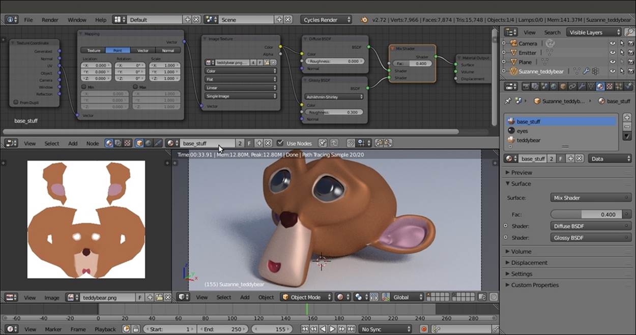
The base_stuff material in the Node Editor window and in the Preview
11. In the Material window, select the teddybear material and switch the Diffuse BSDF node with a Mix Shader node, and label it as Mix Shader1; in the first Shader slot, select another Mix Shader node, and in the second one, select a Transparent BSDF node.
12. Label the second Mix Shader node as Mix Shader2; then, in the first Shader slot, select a Diffuse BSDF shader node, and in the second one, select a Glossy BSDF shader node. Set the Glossy BSDF node's Distribution to Ashikhmin-Shirley, and itsRoughness to 0.200.
13. Add a Fresnel node (press Shift + A and navigate to Input | Fresnel) and connect it to the Fac input socket of the Mix Shader2 node; set IOR to 1.580. Add a Hair Info node (press Shift + A and navigate to Input | Hair Info), and connect the Intercept output to the Fac input socket of the Mix Shader1 node.
14. Add an Image Texture node (press Shift + A and navigate to Texture | Image Texture), and connect its Color output to the Color input socket of the Diffuse BSDF node; click on the little arrows to the left of the Open button to select the already loadedteddybear.png image map.
15. Add a MixRGB node (press Shift + A and navigate to Color | MixRGB), set Blend Type to Add and the Fac value to 1.000, and paste it between the Image Texture node and the Diffuse shader node. Set the Color2 values for R to 0.277, G to 0.179, and B to0.084 and then connect its output also to the Color input socket of the Glossy BSDF shader node.
16. Optionally, add a Texture Coordinate node (press Shift + A and navigate to Input | Texture Coordinate) and a Mapping node (press Shift + A and navigate to Vector | Mapping), and connect the UV output of the Texture Coordinate node to the Vectorinput socket of the Mapping node and the output of the latter to the Vector input socket of the Image Texture node, as shown in the following screenshot:
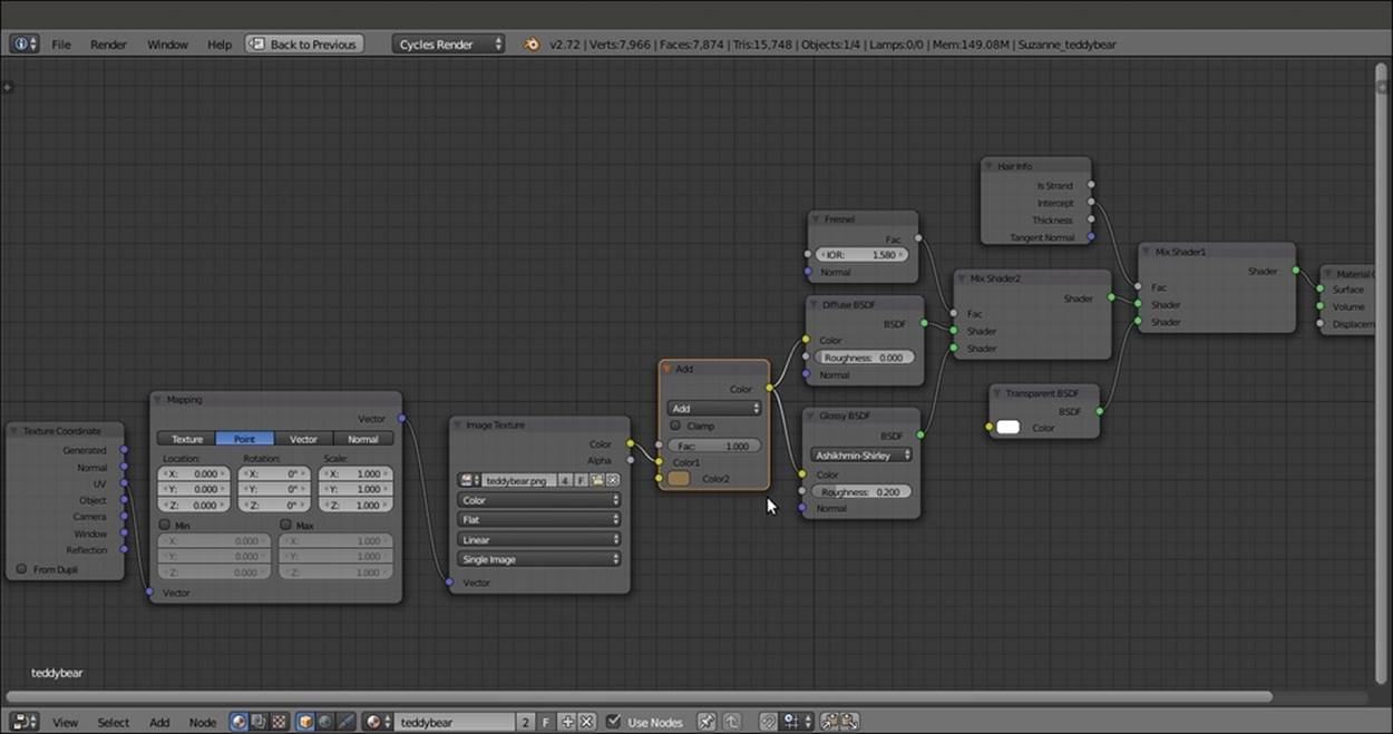
The teddy bear material network; note the transparency driven by the Intercept output of the Hair Info node
How it works...
From step 1 to 3, we prepared the three materials to be used; we went into Edit Mode to assign the second material, eyes, to the eyes vertices of the mesh, and then we went back in Object Mode to add a third material that doesn't need to be assigned to any face of the mesh because they are only to be used for hair rendering.
In steps 4 and 5, we made sure that the right particle system settings for the material are to be rendered as fur.
From step 6 to 8, we built the base_stuff material, a simple basic shader made by the Diffuse and Glossy components mixed by the Mix Shader node and colored by the UV mapped teddybear image texture; note that the texture we used in this first material is also used to give the right color to the hair; it is useful to have it also on the underlying mesh, to cover any hole or missing part in the particle system.
In steps 9 and 10, we built the eyes shader, which is again a very basic material made of the dark Diffuse color and the light gray Glossy components simply mixed by the Mix Shader node.
From step 11 to 16, we built the shader to be used by the particle system for the fur, mixing the already used teddybear.png image map, mapped on the UV coordinates, with a MixRGB node brownish color outputted to the usual Diffuse/Glossy basic shader; note that the Diffuse/Glossy shader is then mixed with the Transparent BSDF shader by the Intercept value of the Hair Info node along the length of each hair strand.
There's more...
The teddybear.png image texture has been used both in the base_stuff and in the teddybear materials; this is often not necessary, because in Blender, the particle system hairs get the textures from the surface they are emitted from, so it would have been enough to use the base_stuff material also for the fur (by selecting it in the Material Slot under the Render subpanel in the Particle window, because we had more than one material on the Suzanne mesh); we had to make a new and different material because we wanted to add a MixRGB brownish color to the UV-mapped image and we had to make the shader fade and become transparent towards the strands' tips.
Note that in the Hair Info node, there is also the Boolean Is Strand output that, similar to the outputs of the Light Path node (Is Camera Ray, Is Shadow Ray, and so on) can be used alternatively to the Material button in the Particle window to assign a material value of 0 to the emitter mesh and a material value of 1 to the fur strands (9931OS_08_hair_isstrand.blend) as shown in the following screenshot:
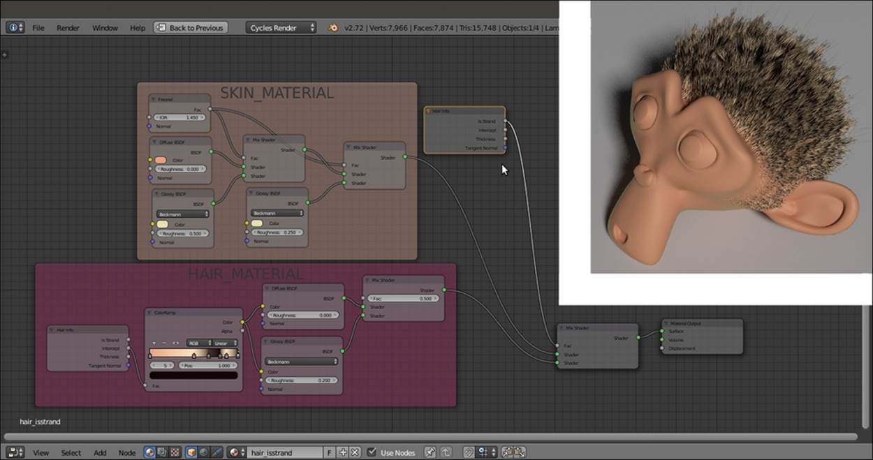
The set up for the hair_isstrand material and the rendered result
This also means that obviously we can also use different image textures to obtain fur materials different from the material of the particle emitter: for example, in the following screenshot, the tiger.png image texture has been used only for the fur, whereas thebase_stuff material still uses the teddybear.png texture (and, honestly, this is blatantly visible... better to use the same image both for fur and emitter):

The rendered Suzanne_tiger object
The Suzanne_tiger object also has two different particle systems to create the fur, tigerfur_long and tigerfur_short, and three Vertex Groups to modulate the fur appearance, density_long, density_short, and length.
To take a look at the Suzanne_tiger object, open the 9931OS_08_tiger.blend file.
See also
· http://wiki.blender.org/index.php/Doc:2.6/Manual/Render/Cycles/Hair_Rendering
· http://wiki.blender.org/index.php/Doc:2.6/Manual/Render/Cycles/Nodes/More
· http://blenderdiplom.com/en/tutorials/all-tutorials/536-tutorial-fur-with-cycles-and-particle-hair.html
· http://cgcookie.com/blender/2014/04/24/using-cycles-hair-bsdf-node/
Creating a gray alien skin material with procedurals
In this recipe, we will create a gray alien-like skin shader as shown in the following screenshot, using Cycles procedural textures:
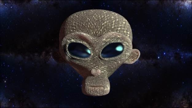
The alien Suzanne as it appears in the final rendering
Getting ready
Start Blender and open the 9931OS_08_alienskin_start.blend file, where there is an already set scene with an unwrapped Suzanne primitive object.
The Suzanne_unwrapped_alien mesh has been modified by a shape key, to morph its monkey features into the head of a gray alien–like creature; in fact, in the Object data window, under the Shape Keys subpanel, there are the alien shape keys, with Value of1.000; sliding the slider towards 0.000 gradually restores the original Suzanne shape.
The Suzanne mesh also has a Vertex Colors layer named Col and is obtained by the Dirty Vertex Colors tool.
On the second layer, there are two Planes tracked (by a Damped Track constraint, in the Object Constraints window) to the Camera to stay perpendicular to its point of view; the star_backdrop object is used to create a simple star backdrop for our alien Suzanne, and the star_backdrop.001 object is used simply to create something to be reflected by the alien-like Suzanne's eyes.
Press Shift + F1 (or go through the File | Append main menu) to append the SSS_group node from the 9931OS_07_SSS_ngroup.blend file.
How to do it...
Let's start by first setting the background image material using the following steps:
1. Select the star_backdrop Plane and click on the New button in the Node Editor window toolbar or in the Material window. Rename the material star_backdrop, and in the Material window, switch the Diffuse BSDF shader with an Emission shader. Set theStrength to 0.500.
2. Add an Image Texture node (press Shift + A and navigate to Texture | Image Texture) and connect the Color output to the Color input socket of the Emission node. Click on the Open button and browse to the textures folder and load the centre-of-milky-way_tile_low.png image.
3. Add an RGB Curves node (press Shift + A and navigate to Color | RGB Curves) and paste it between the Image Texture and Emission nodes. Click on the curve window to add a control point and set these coordinates: X to 0.36667 and Y to 0.12778. Click again to add a second control point and set these coordinates: X to 0.65556 and Y to 0.81111.
4. Add a Mix Shader node (press Shift + A and navigate to Shader | Mix Shader) and paste it between the Emission and Material Output nodes; switch the connection that comes from the Emission node to the second Shader input socket of the Mix Shadernode; leave the first Shader input socket empty.
5. Add a Light Path node (press Shift + A and navigate to Input | Light Path) and connect the Is Camera Ray output to the Fac input socket of the Mix Shader node.
6. Go to Outliner and select the star_backdrop.001 object; click on the double arrows icon to the left side of the data block name (Browse Material to be linked) in the Node Editor toolbar, and select the star_backdrop material; click on the 2 icon button to make it single-user.
7. In the new star_backdrop.001 material, select the Mix Shader node and press Ctrl + X to delete it and keep the connection; then, also delete the Light Path node.
8. Go to the Object data window, and in the Ray Visibility subpanel, uncheck all the items except for the Glossy one.
Now, let's get started with the creation of the alien skin shader (also with a different material for the eyes).
9. Select the Suzanne_unwrapped_alien object; click on the New button in the Node Editor window toolbar or in the Material window, and rename the material alienskin.
10. Go into Edit Mode, select the eyes vertices, and click on the + icon on the right of the Material window to add a second material. Click on the New button and rename the material as alieneyes; then, click on the Assign button to assign it to the selected vertices. Go out of Edit Mode.
11. Switch the Diffuse BSDF shader with a Mix Shader node; in the first Shader slot, select a Diffuse BSDF shader, and in the second one, select a Glossy BSDF shader. Set the Mix Shader node's Fac value to 0.600 and the Diffuse BSDF node's Colorvalues for R to 0.010, G to 0.006, and B o 0.010; set the Glossy BSDF node's Distribution to Beckmann, change the Color values for R to 0.345, G to 0.731, and B to 0.800, and change the Roughness value to 0.100.
12. Select the alienskin material, and in the Material window, switch the Diffuse BSDF shader with an Add Shader node (label it as Add Shader1); in the first Shader slot, select a Mix Shader node, and in the second one, load the appended SSS_group node. In this node, set the Contrast value to 3.000 and change the Color values for R to 0.834, G to 0.263, and B to 0.223.
13. Go to the Mix Shader node, and in the first Shader slot, select a Diffuse BSDF node, and in the second one, select a new Add Shader node (label it as Add Shader2). Set the Diffuse BSDF node's Roughness value to 0.800.
14. In both the Shader slots of the Add Shader2 node, select a Glossy BSDF shader node; label the first one as Glossy BSDF 1 and the second as Glossy BSDF 2; set Distribution of both to Beckmann, and then set the Roughness value of the first one to0.600 and that of the second one to 0.300.
15. Add a Fresnel node (press Shift + A and navigate to Input | Fresnel) and connect its output to the Fac input socket of the Mix Shader node. Set the IOR value to 1.300, as shown in the following screenshot:
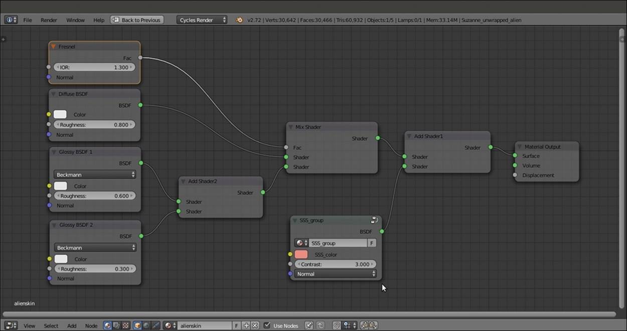
The basic shader network with the SSS provided by the appended node group
Now that we have set the basic shader for the alien skin, let's set an important component of the material, that is, the bump, by following these steps:
16. Add a Texture Coordinate node (press Shift + A and navigate to Input | Texture Coordinate) and two Mapping nodes (press Shift + A and navigate to Vector | Mapping); connect the UV output of the Texture Coordinate node to the Vector input socket of both the Mapping nodes, labeled as Mapping1 and Mapping2 respectively.
17. Set the Rotation value of Y of the Mapping1 node to 60°; set the Rotation value of Y of the Mapping2 node to 20°.
18. Add two Voronoi Texture nodes (press Shift + A and navigate to Texture | Voronoi Texture) and label them as Voronoi Texture1 and Voronoi Texture2. Connect the Mapping1 node output to both their Vector input sockets. Set the Scale value of the Voronoi Texture1 to 100.000 and the Scale value of the Voronoi Texture2 to 20.000.
19. Add two Wave Texture nodes (press Shift + A and navigate to Texture | Wave Texture) and label them as Wave Texture1 and Wave Texture2. Connect the Mapping1 node output to the Vector input socket of the Wave Texture1 node. Set the texture Scalevalue to 20.000, Distortion to 10.000, Detail to 16.000, and Detail Scale to 0.300.
20. Connect the Mapping2 node output to the Wave Texture2 node's Vector input socket, and set all the texture values exactly as in the previously described one.
21. Add a Noise Texture node (press Shift + A and navigate to Texture | Noise Texture) and label it as Noise Texture1. Connect the Mapping2 node output to its Vector input socket, and set the texture Scale value to 120.000 and the Detail value to 7.000.
22. Add a ColorRamp node (press Shift + A and navigate to Converter | ColorRamp), label it as ColorRamp1, and connect the Voronoi Texture1 node's Color output to its Fac input socket. Set Interpolation to Ease and move the white color stop to the 0.126position.
23. Add a Math node (press Shift + A and navigate to Converter | Math), change Operation to Multiply, and label it as Multiply1. Connect the Color output of the ColorRamp1 node to the first Value input socket of the Multiply1 node, and set the second Valueto 0.050.
24. Add a MixRGB node (press Shift + A and navigate to Color | MixRGB) and connect the Color output of the Voronoi Texture2 node to the Color1 input socket, and the Color output of the Wave Texture1 node to the Color2 input socket. Set Blend Type toDifference and the Fac value to 1.000, and then label it as Difference1.
25. Add a second MixRGB node (press Shift + A and navigate to Color | MixRGB) and connect the Color output of the Voronoi Texture2 node to the Color1 input socket, and the Color output of the Wave Texture2 node to the Color2 input socket. Again, set the Blend Type to Difference and the Fac value to 1.000 and label it as Difference2.
26. Add two ColorRamp nodes (press Shift + A and navigate to Converter | ColorRamp), and label them as ColorRamp2 and ColorRamp3; connect the Difference1 node output to the Fac input socket of the ColorRamp2 node, and the output of the Difference2node to the Fac input socket of the ColorRamp3 node.
27. Set Interpolation to B-Spline for both of them, and for both of them, move the white color stop to the 0.255 position.
28. Add a MixRGB node (press Shift + A and navigate to Color | MixRGB) and connect the Color output of the ColorRamp2 node to the Color1 input socket and the Color output of the ColorRamp3 node to the Color2 input socket. Set the Blend Type toMultiply and the Fac value to 1.000. Label it as Multiply2.
29. Press Shift + D to duplicate the Multiply1 node and label the duplicate as Multiply3. Connect the output of the Multiply2 node to the first Value input socket of the Multiply3 node. Set the second Value to 0.050.
30. Press Shift + D to duplicate the Multiply3 node and label the duplicate as Multiply4. Connect the Color output of the Noise Texture node to the first Value input socket of the Multiply4 node, and set the second Value to 0.175.
31. Add a Math node (press Shift + A and navigate to Converter | Math) and label it as Add1. Connect the output of the Multiply1 node to the first Value input socket and the output of the Multiply3 node to the second Value input socket.
32. Press Shift + D to duplicate the Add1 node and label the duplicate as Add2; connect the output of the Add1 node to the first Value input socket and the output of the Multiply4 node to the second Value input socket.
33. Add a Bump node (press Shift + A and navigate to Vector | Bump) and connect the output of the Add2 node to the Height input socket of the Bump node; set its Strength value to 4.000 and connect its Normal output to the Normal input sockets of theDiffuse BSDF node, of the two Glossy BSDF nodes, and of the SSS_group node, as shown in the following screenshot:
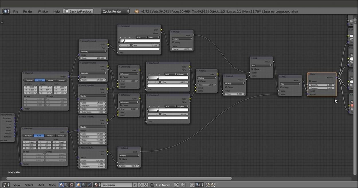
The apparently complex bump network to be connected as per the shader bump
We are done with the bump part, so now, let's set the color pattern using the following steps:
34. Add a ColorRamp node (press Shift + A and navigate to Converter | ColorRamp), label it as ColorRamp4, and connect the Color output of the Multiply2 node to its Fac input socket. Set Interpolation to Ease and move the black color stop to the 0.495position, and the white color stop to the 0.000 position.
35. Add a MixRGB node (press Shift + A and navigate to Color | MixRGB), set the Blend Type to Add, and label it as Add3. Connect the Color output of the ColorRamp4 node to the Fac input socket and set the Color2 values for R to 0.553, G to 0.599, and B to0.473.
36. Add a Noise Texture node (press Shift + A and navigate to Texture | Noise Texture) and label it as Noise Texture2. Connect the Mapping1 node output to its Vector input socket and set the texture's Scale value to 60.000 and the Detail value to 7.000.
37. Add a ColorRamp node (press Shift + A and navigate to Converter | ColorRamp), label it as ColorRamp5, and connect the Noise Texture2 color output to its Fac input socket. Set Interpolation to B-Spline and move the black color stop to the 0.486 position and the white color stop to the 0.771 position.
38. Press Shift + D to duplicate the Add3 node, label the duplicate as Add4, and connect the Color output of the ColorRamp5 node to its Fac input socket; connect the output of the Add3 node to the Color1 input socket and set the Color2 values for R to 0.235, Gto 0.198, and B to 0.132.
39. Press Shift + D to duplicate the Add4 node, label the duplicate as Overlay, and change Blend Type to Overlay as well. Set the Fac value to 1.000 and connect the output of the Add4 node to the Color1 input socket.
40. Add an Attribute node (press Shift + A and navigate to Input | Attribute) and connect its Color output to the Color2 input socket of the Overlay node; in the Name field, write Col (the Vertex Colors layer).
41. Connect the output of the Overlay node to the Color input socket of the Diffuse BSDF shader node.
42. To make them more easily readable, frame the three groups of nodes, SHADER, BUMP, and COLOR, as shown in the following screenshot:
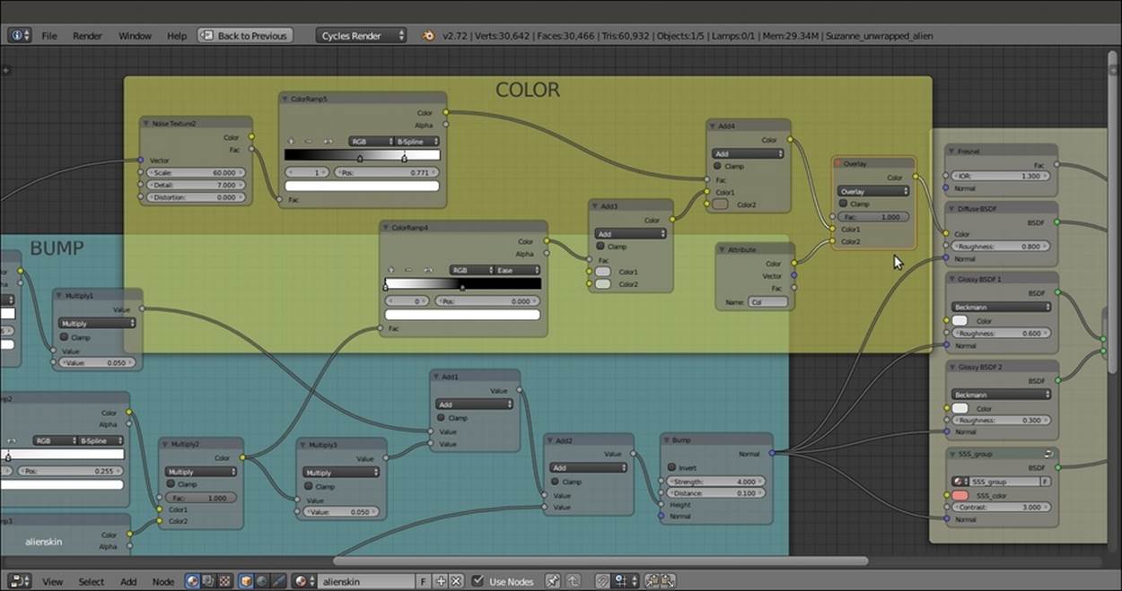
The simpler color pattern to be connected only to the Diffuse shader node and the nodes grouped by frames
43. Save the file as 9931OS_08_alienskin_final.blend.
How it works...
· From step 1 to 8, we built a simple and quick shader for the starry background and for the Plane in front of the Suzanne_unwrapped_alien mesh to be reflected in the eyes; note that the background Plane material works as a shadeless material. To see how to set a bright but not emitting light background, that is, a shader that behaves as the shadeless material you have in the Blender Internal engine, go to Chapter 9, Special Materials.
· From step 9 to 15, we built the basic shader for the alien Suzanne's skin; the diffuse component is mixed and modulated by the Fresnel output, with a specular component made by two summed Glossy BSDF nodes with different roughness values, so as to have a crisper specular effect on a more diffuse one, and with the additional help of the SSS_group node to simulate a reddish Subsurface Scattering effect.
· From step 16 to 33, we built the quite complex bump pattern for the skin by mixing the outputs of three different types of procedural textures with the help of both the Math and MixRGB nodes, and the variations provided by the ColorRamp nodes.
· Finally, from step 34 to 41, a simple grayish color pattern is modulated through the Dirty Vertex Colors layer data that comes from the mesh and that uses the first part of the bump pattern to add variation.
All materials on the site are licensed Creative Commons Attribution-Sharealike 3.0 Unported CC BY-SA 3.0 & GNU Free Documentation License (GFDL)
If you are the copyright holder of any material contained on our site and intend to remove it, please contact our site administrator for approval.
© 2016-2026 All site design rights belong to S.Y.A.