Blender Cycles: Materials and Textures Cookbook, Third Edition (2015)
Chapter 2. Managing Cycles Materials
In this chapter, we will be covering the following recipes:
· Preparing an ideal Cycles interface for material creation
· Naming materials and textures
· Creating node groups
· Grouping nodes under frames for easier reading
· Linking materials and node groups
Introduction
As with Blender Internal materials, Cycles materials can (and should) be organized to optimize your workflow.
Material nodes in Cycles can easily grow quite complex, and it's sometimes a good idea to split and label the different parts of a shader's network, just to make the meaning of the different sections clearer (even to yourself because maybe at a certain point of your workflow, you will forget how exactly that 120-node material you made a couple of months ago works). Moreover, organized materials can be easily reused in other files and projects or as parts of bigger and different materials.
Organization of materials is basically done by grouping them or giving them proper names and defined locations so that they can be easily found in the hard disk.
Preparing an ideal Cycles interface for material creation
Before starting with the actual organization, it's a good idea to prepare a material creation screen to be saved in your Blender preferences.
It is possible, in fact, to prepare a basic scene setup that includes the elements and the settings we need to do the job best.
In any case, just take this recipe with a grain of salt, that is, take it as more of a suggestion or as a starting point that you can eventually modify to better suit your needs.
Getting ready
Start Blender and in the upper menu (the Engine to use for rendering button), switch to Cycles Render.
How to do it...
We are now going to customize the Default screen:
1. Split the 3D view into two horizontal rows. To do this, move the mouse cursor onto the lateral edge of the window. The cursor changes to a double arrow icon. Right-click on the edge, and from the little pop-up menu that appears, select Split Area (or click in the top-right corner of the window and move it).
2. Change the upper window to a Node Editor window by selecting the item from the Editor Type button in the left corner of the bottom bar (or by putting the mouse cursor in the window and pressing the Shift + F3 keyboard shortcut).
3. Select the default Cube in the scene if it is not selected already, and go to the Object modifier window under the Properties panel to the right of the screen. Assign a Subdivision Surface modifier to the Cube, which is now a Spheroid, and set theSubdivisions levels for both View and Render to 4. Check the Optimal Display item.
4. Set the Spheroid shading mode to Smooth by clicking on the appropriate button under the Shading subpanel in the Tools tab on the left.
5. Move the Spheroid upward by 2 units on the z axis (press G, then press Z, enter digit 2, and finally, press Enter).
6. Ensuring that the cursor is still at the center of the scene (if not, press Shift + C to center it), press Shift + A and navigate to Mesh | Plane to add a Plane.
7. Press Tab to go to Edit Mode and scale the Plane four times bigger (press Tab, then press S, enter digit 4, and finally, press Enter). Exit Edit Mode.
8. Split the bottom row into two parts, put the mouse cursor in the 3D window on the right, and press 0 in the numeric keypad of the keyboard to go to the Camera view. Then press T to close the Tool Shelf panel with the tabs on the left. Scroll the mouse wheel to fit the Camera view field into the window (or for a finer control, press Ctrl + the middle button of the mouse and move the mouse).
This screenshot shows where we are now:
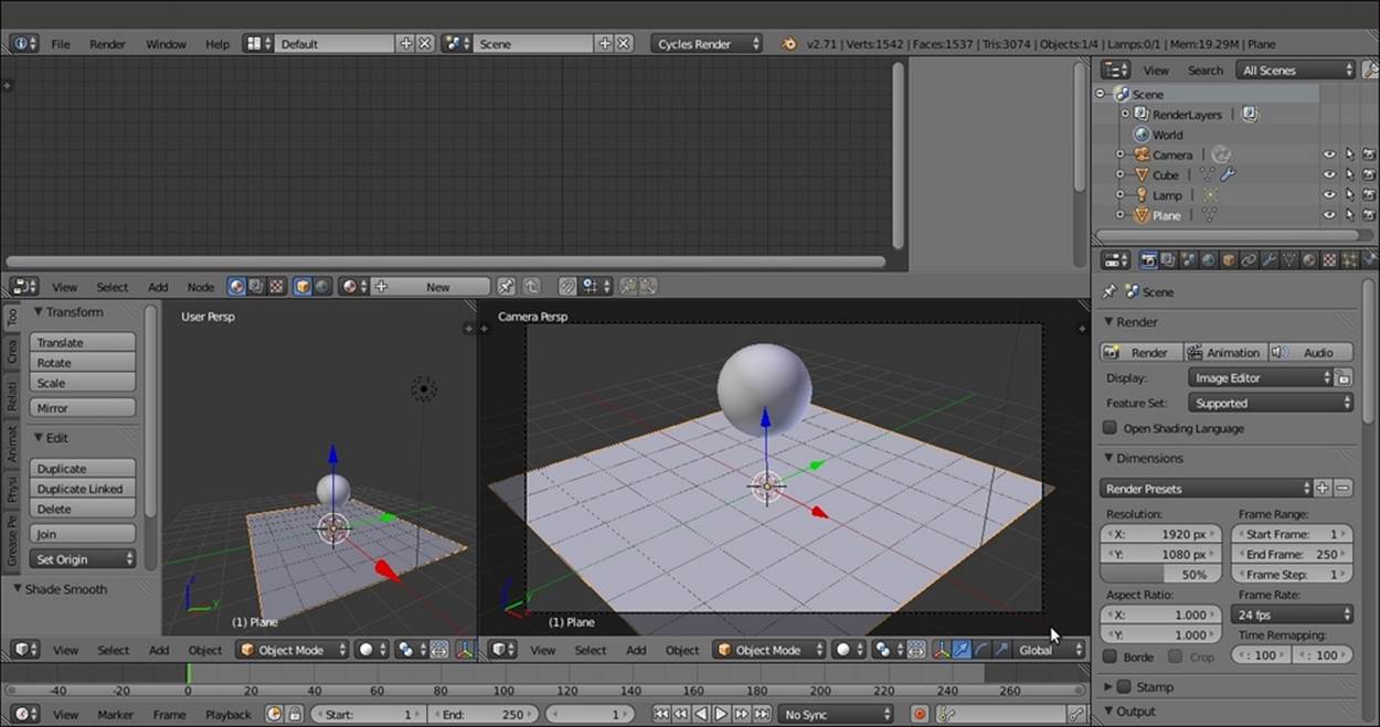
The first steps of the Default screen customization for Cycles material creation
9. In the Editor Type button in the left corner of the bottom bar of the left 3D window, select UV/Image Editor.
10. Select the Spheroid, go to Edit Mode, and scale it to twice the current size (press Tab, then press S, enter digit 2, and finally, press Enter). Exit Edit Mode.
11. Move the mouse to the Camera view and press Shift + F to enter Walk Navigation mode (a viewfinder appears to show the center of the camera field). By moving the mouse to pan and by pressing the W or the S key to go forward or backward, respectively, adjust the Camera view to fit the Spheroid better. Then press Enter or click to confirm, as shown in the following screenshot:
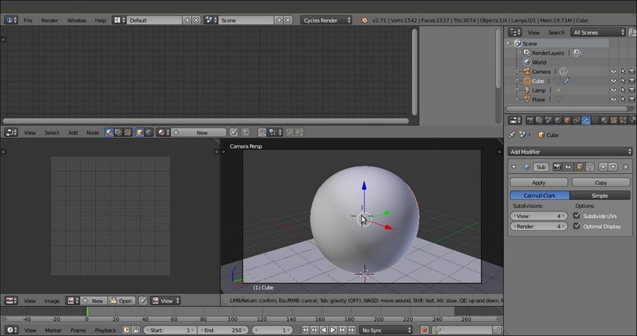
Centering the Camera view on the Spheroid
12. Select the Plane. Click on New in the Node Editor toolbar to assign a new material (Material.001). Rename it Plane and leave all the settings as they are.
13. Select the Spheroid and click on Use Nodes in the Material window under the Properties panel to the right of the screen or in the Node Editor toolbar.
14. Put the mouse in the Node Editor window and scroll the wheel to zoom to the nodes.
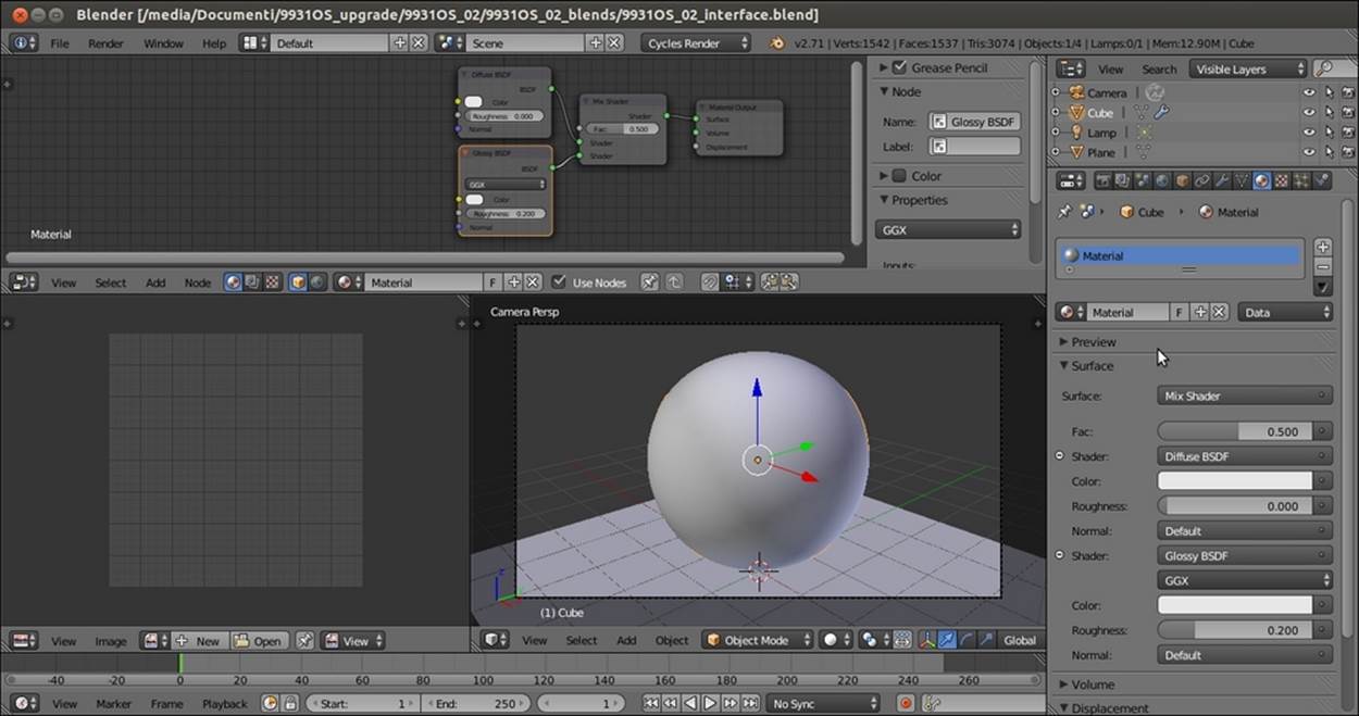
15. Under the Surface subpanel in the Material window, switch the Diffuse BSDF shader with a Mix Shader node. Then click on the first Shader slot to select a Diffuse BSDF shader and on the second slot for a Glossy BSDF shader (the two Shader slots I'm referring to are highlighted in the next screenshot).
16. In the Node Editor window, adjust the position of the nodes to make them more readable, as shown in this screenshot:
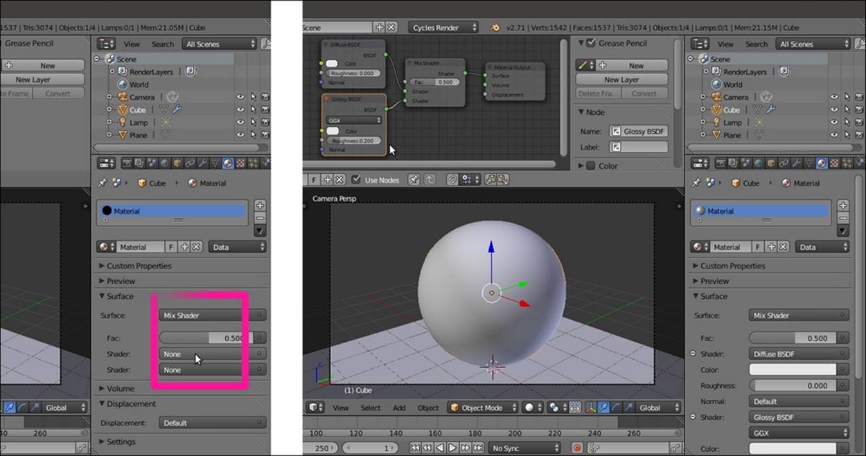
Preparing a basic average material with the Diffuse and the Glossy components
17. Set the Camera view mode to Rendered by clicking on the Viewport Shading button on the window toolbar and selecting the top item or by pressing Shift + Z with the mouse cursor inside the 3D view.
18. Go to the Render window under the Properties panel on the right, and under the Sampling subpanel, set both Clamp Direct and Clamp Indirect to 1.00, and both Render and Preview to 50 samples.
19. Under the Light Paths subpanel, set Filter Glossy to 1.00.
20. Go to the Outliner window and select the Lamp item. Go to the Object data window under the Properties panel and click on the Use Nodes button under the Nodes subpanel. Increase the Strength value to 300.000.
Now the output will look like what is shown in this screenshot:
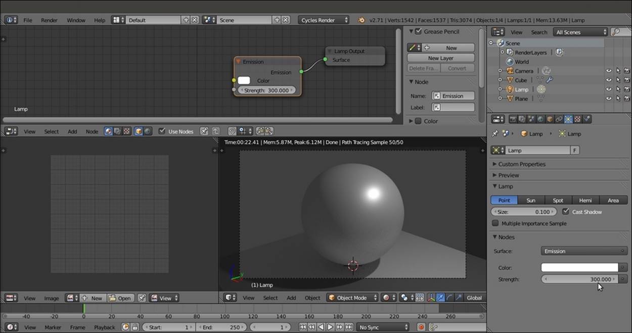
Setting the Camera view to Rendered and increasing the Lamp strength
21. Go back to the Render window under the Properties panel and set the Percentage scale for render resolution under Dimensions to 25% to have smaller but faster rendering.
22. Under the Performance subpanel, set Viewport BVH Type to Static BVH and check Use Spatial Splits, Cache BVH, and Persistent Images (these are probably not really useful for a simple Spheroid, but they are useful if you want to render a more complex object).
23. Go to the World window and click on the Use Nodes button under the Surface subpanel. Click on the Color slot, set the RGB values to 0.100, and set the Strength value to 0.100.
24. Set the Factor value for the Ambient Occlusion subpanel to 0.05 but let it remain disabled. You can enable the Ambient Occlusion subpanel or not, depending on your preferences, but remember that it adds light to the rendered image. I would say that it's usually better not to have the Ambient Occlusion subpanel activated by default but enabled only if really needed. In this case, the very low value can compensate a bit for the darkened background of the World, which is shown in the following screenshot for your reference:
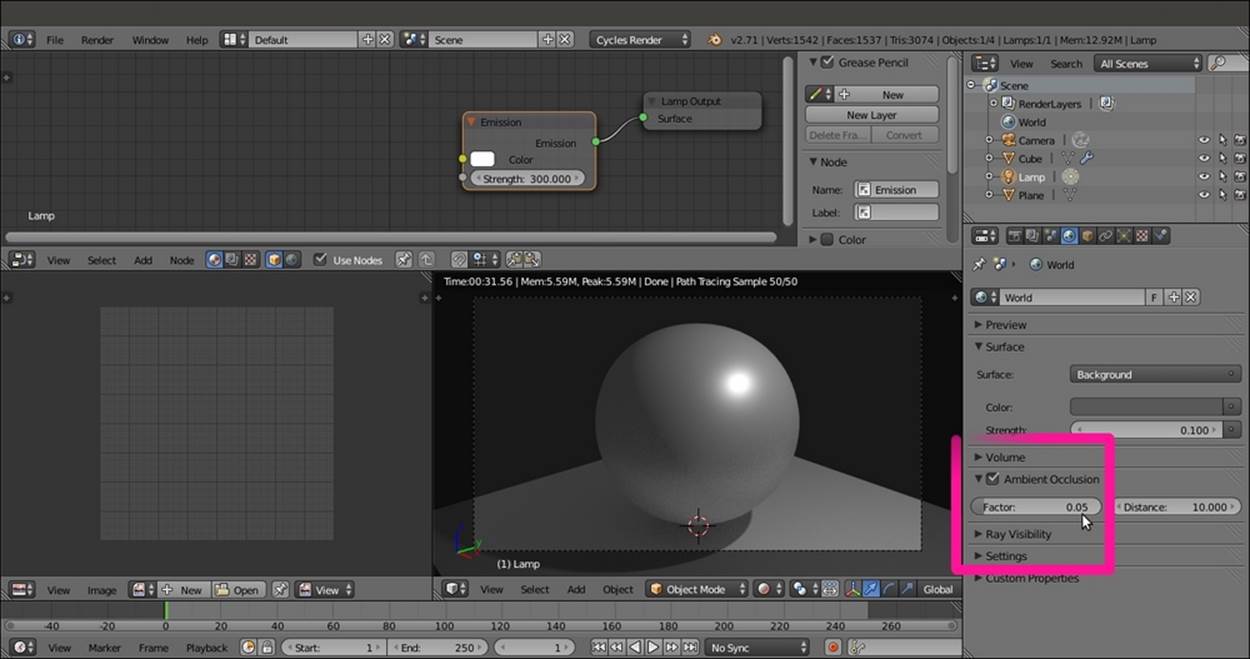
Preparing the optional Ambient Occlusion setting
Optionally, other things that you can do include scaling the floor Plane bigger. In the Outliner window, set the mode to Visible Layers and click on the arrow icon to the side of the Plane item to make it nonselectable. Substitute Lamp, the default Point item, with a different type (Sun or Spot) or with a mesh-light plane.
25. Go back to the Material window. If you want to save this setting as the user default, press Ctrl + U (Save Startup File), or save the file with a meaningful name. Among the files provided with this book, you will find this file by the name of9931OS_02_interface.blend. The 3D view now looks like what is shown in the following screenshot:
The final overall look of the customization
How it works...
We set a very low World global illumination, keeping its color within the gray scale in order not to affect the color of the material. The floor plane is meant to have light bouncing on the shadowed parts of the object, and this can eventually be helped by the lowAmbient Occlusion subpanel as well.
We prepared the Rendered view port as a Camera view to get better feedback for the final rendered image, which will show at 25 percent of the established size in the UV/Image Editor window on the bottom-left side of the screen.
By setting the Clamp values to 1.00, we reduced the fireflies produced by the glossy shader, and by increasing the render and preview samples to 50, we reduced the noise, at the same time keeping the rendering times reasonable, even with a not-very-powerful workstation.
The Viewport BVH Type is set to Static BVH, and the Use Spatial Splits, Cache BVH, and Persistent Images options are useful to reduce the calculation time for the bounding volume hierarchy of the mesh, which Cycles has to calculate every time it starts rendering. Anyway, these options are useful only if the mesh doesn't get any internal modification between renderings.
There's more...
From now on, every time we start Blender, the layout and the settings we just saved as default will be seen first.
But maybe we don't want to have this Cycles material interface every time we start, and we prefer to have it only as an option to be used if needed. Actually, in the previous steps, we modified the Default screen, but it's also possible to create new screens while keeping the original screen available. Here is the way to do this:
1. Start Blender with the factory settings (click on the File menu on the top main header and navigate to Load Factory Setting) and look at the top of the screen, in the main header on the side of the Blender Render button. There are two more buttons labeledDefault and Scene.
2. By clicking on the Default button, we can set a different interface layout (there are already nine, each of which is studied for a different task, and their names are perfectly explicative). Clicking on Scene shows just the current scene.
3. By clicking on the + icon on the side of the Default button, we add a new screen layout named Default.001. Rename it Materials.
4. Then click on the + icon on the side of the Scene button, and by choosing the Full Copy item, add a new scene to the Scene.001 file. Rename the file as something like Cycles_Materials. This new scene is a full copy of the default scene, coexisting but independent.
At this point, we can start with all the instructions already seen in the How to do it section of this recipe: switching to Cycles Render, splitting the 3D window, assigning the Subdivision Surface modifier to the default Cube, and so on.
When done, just click on the screens button, switch back to Default, and then save the user preferences (Ctrl + U). Now our material creation interface is saved as a screen option in a different scene. Every time we need to access it, it's enough to select the layoutMaterials from the screens button.
Naming materials and textures
It is well known that one of the most important things to do when working in every workflow with every 3D package is to give proper and explicative names to all the assets, that is, to the materials and the textures in our case.
Getting ready
Start Blender, go to the File menu in the top-left corner, and choose Load Factory Setting (this is just to be sure to start with the default Blender/Cycles settings).
Now, if you are in Blender Internal mode, switch to Cycles Render.
How to do it...
Now let's see the way material and texture naming works in Cycles.
Materials:
Adding and renaming materials in the Material window is done by performing the following steps:
1. Select the default Cube. Go to the Material window in the Properties panel. The default Cube already has a material assigned. This material has already been named Material by Blender, as shown in the following screenshot:
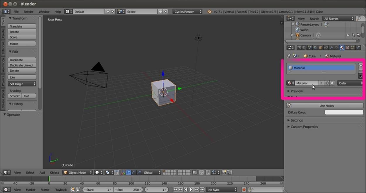
The material name datablock under the Material window
2. When you create a new material, for example, by clicking on the + symbol on the side of the material data block (add a new material) under the Properties panel, Blender automatically assigns a new name to this material, which is usually something likeMaterial.001, Material.002, Material.003, and so on.
Having an automatic nomenclature can be handy in most cases, but it can become really confusing as a scene grows in complexity or if you have to reuse some of the materials in other situations. In such cases, we'd better rename all our materials with significant names.
To rename a material, it's enough to click with the left mouse button on the material name data block, type a new name, and then press Enter to confirm. This can be done in both the Properties panel and in the Material datablock button on the toolbar of the Node Editor window, as shown in the following screenshot:
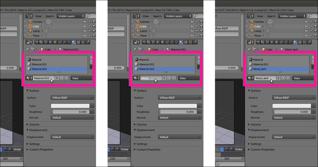
Adding and renaming materials in the Material window
Textures:
Things are a little different for textures. In Cycles, textures are no more data blocks but nodes, so every time we add a Texture node to a material network, it automatically gets named according to the kind of texture we added. This means that if we add a Voronoi Texture, the texture node is automatically named Voronoi Texture. What if we want to rename it to avoid confusion among three or four Voronoi Texture nodes? To rename the texture, perform the following steps:
1. Open the 9931OS_02_interface.blend file.
2. Go to the Node Editor window and press Shift + A to add a Voronoi Texture node to the material (press Shift + A and navigate to Texture | Voronoi Texture).
On the right side of the Node Editor window, there is a Properties panel with several subpanels (press the N key if it's not already present). What interests us now is the Node subpanel with its two slots, Name and Label.
As you can see, the name of the node (Voronoi Texture) is already present in the Name slot. By clicking on the name, it's possible to change it, but at the moment, this seems useful to identify the node in the Properties panel.
The Label slot, which is empty by default, can be used to label a node in the Node Editor window.
3. Press Shift + D to duplicate the Voronoi Texture node. The duplicated node is automatically named Voronoi Texture.001.
4. Select the first Voronoi Texture node and write Voronoi_Diffuse in the Label slot of the Properties panel. Connect this node to the Color input socket of the Diffuse BSDF shader node.
5. Select the duplicated Voronoi Texture node and write Voronoi_Glossy in the Label slot of the Properties panel. Connect this node to the Color input socket of the Glossy BSDF shader node, as shown in the following screenshot:
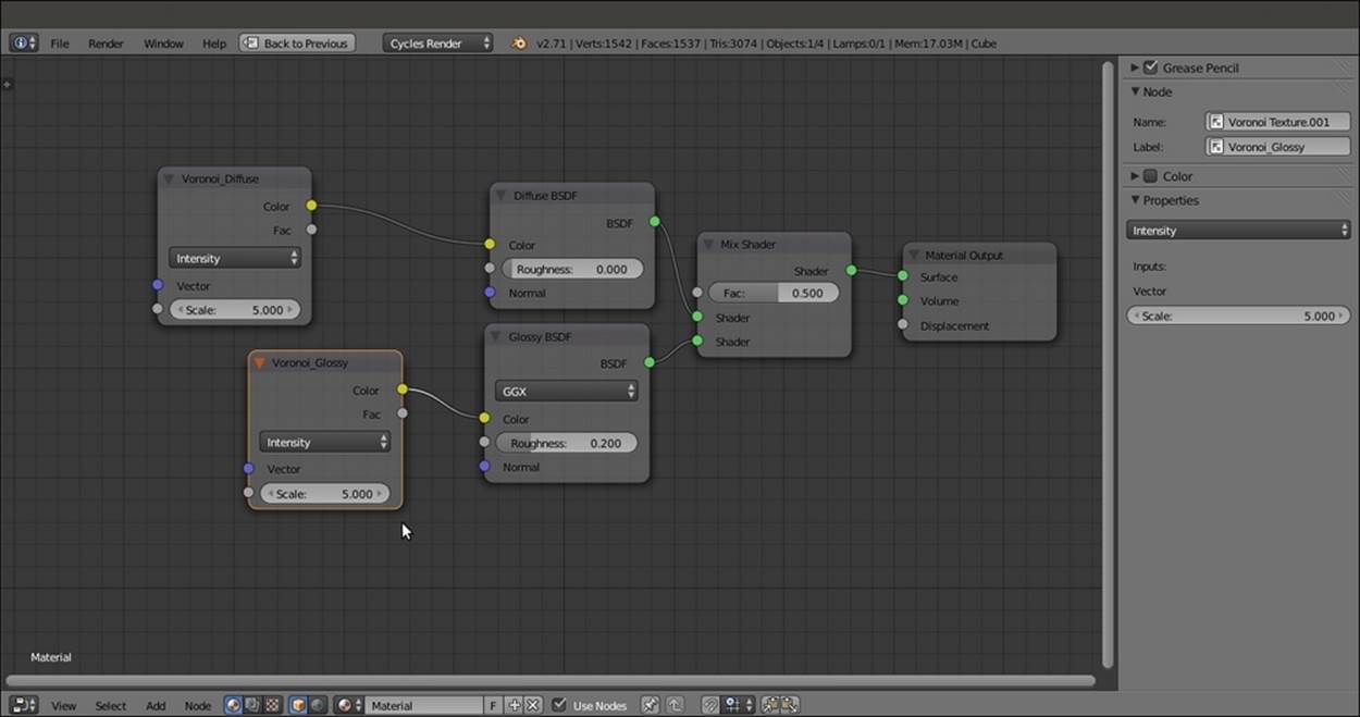
The labeling of the nodes through the Active Node subpanel in the Node Editor Properties side-panel
There's more...
Even though this is not strictly related to renaming, let's quickly see one more option. Right below the Node subpanel, there is the Color subpanel. Once enabled, this subpanel permits us to assign a color to the selected node to further increase the readability in the Node Editor window, as shown in this screenshot:
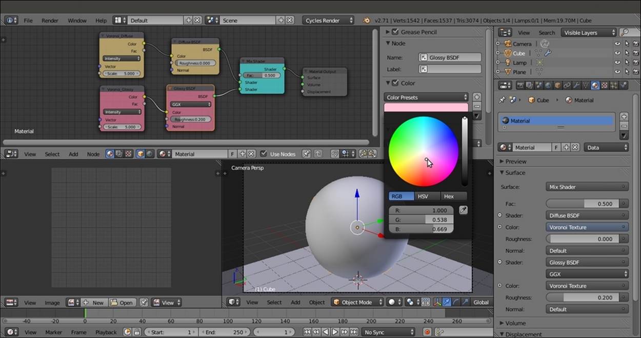
Using colors to further label the nodes
Creating node groups
Single nodes (shaders, textures, input, or whatever) can be grouped together, and this is probably one of the best ways to organize our workflow.
Thanks to node groups, it's easy to store complex materials in ready-to-use libraries. It's possible to share or reuse them in other files, and they can also be used to build handy shader interfaces for easier tweaking of material properties.
Getting ready
Start Blender and open the 9931OS_02_interface.blend file.
How to do it...
Let's go to the Node Editor window directly:
1. Now box-select (place the mouse cursor in the Node Editor window, press B, and click and drag a box to include the nodes you want to select) the Diffuse BSDF and the Glossy BSDF nodes, as shown in this screenshot:
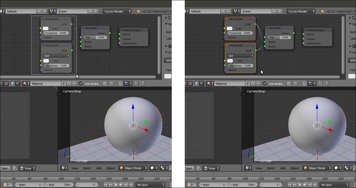
Box-selecting two nodes
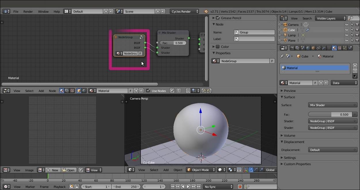
2. Press Ctrl + G on the keyboard. The background of Node Editor changes, showing that now we are in Edit Mode inside a group. In fact, there are two selected nodes with a Group Input node and a Group Output node. Also, the Surface subpanel under theMaterial window has changed, and in the Node Editor in the Properties panel, a new Interface tab has appeared, as shown in the following screenshot:
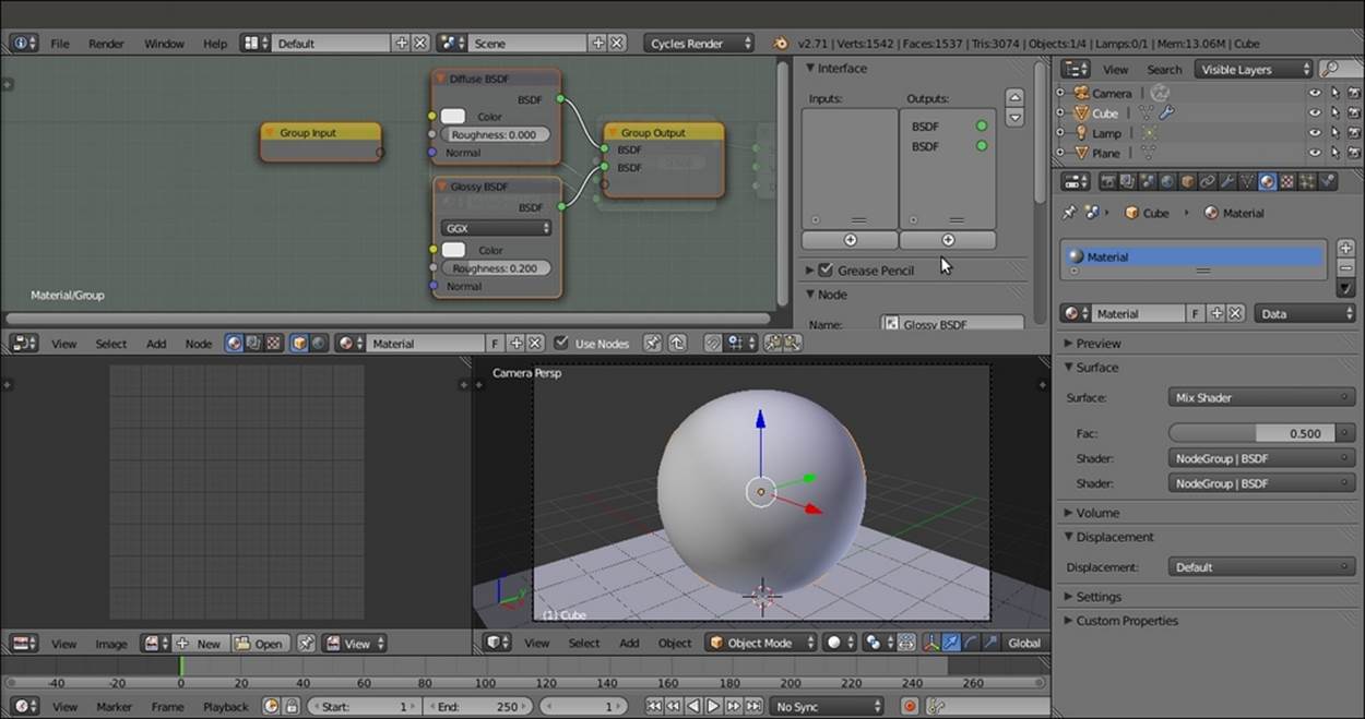
The appearance of the just created and open for editing node group inside the Node Editor window
3. Because the two shaders were already connected to Mix Shader (which, in this case, we left out of the group on purpose), both the Diffuse BSDF and the Glossy BSDF outputs are now connected to two BSDF sockets automatically created on the Group Output node.
4. As for every Edit Mode in Blender, by pressing the Tab key, we go out of Edit Mode, closing the node group, as shown in this screenshot:
The closed node group
The node group is still showing the two BSDF outputs (actually connected to the input sockets of the Mix Shader node), the name data block, and the fake user button (F). This last one is the same as in Blender Internal. It prevents the user count from ever becoming zero, and therefore prevents the deletion of any non-assigned material. When you save the file and/or close Blender by assigning the fake user to a non-assigned material, you are sure that it will not be deleted. This is particularly handy when you are building a material library.
5. Now click on the name data block of the node group and change the default name, NodeGroup, to something else. I wrote BasicShader.
6. Press Tab and go to Edit Mode again. Click on the only empty socket in the Group Input node and drag a link to the Color input socket of the Diffuse BSDF node. The empty socket now connected to the Diffuse BSDF node has changed and is now indicated as Color. Moreover, a new empty socket has appeared on the Group Input node, as shown in the following screenshot:
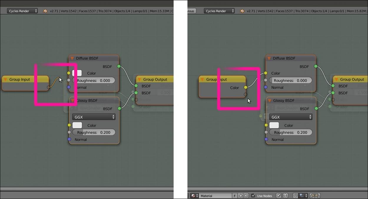
Editing the node group by connecting inner sockets to expose them
7. Repeat the previous step for the new empty input socket and connect it to the Color input socket of the Glossy BSDF node. Again, a new empty socket has appeared, ready to be connected to something else.
8. Now look at the Properties panel to the right. The Interface subpanel is reflecting what we are doing in the Node Editor. In fact, in the little Input window, there are two Color sockets, and we can double-click to rename them (Color1 and Color2 in our case). To remove a socket, just click on the name in the Properties panel, and then click on the X icon in the bottom Name slot, as shown in this screenshot:
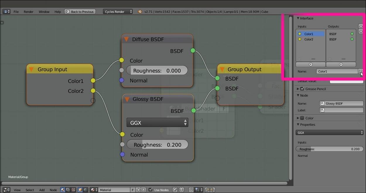
Renaming and ordering the new input sockets through the Interface subpanel in the Properties side-panel
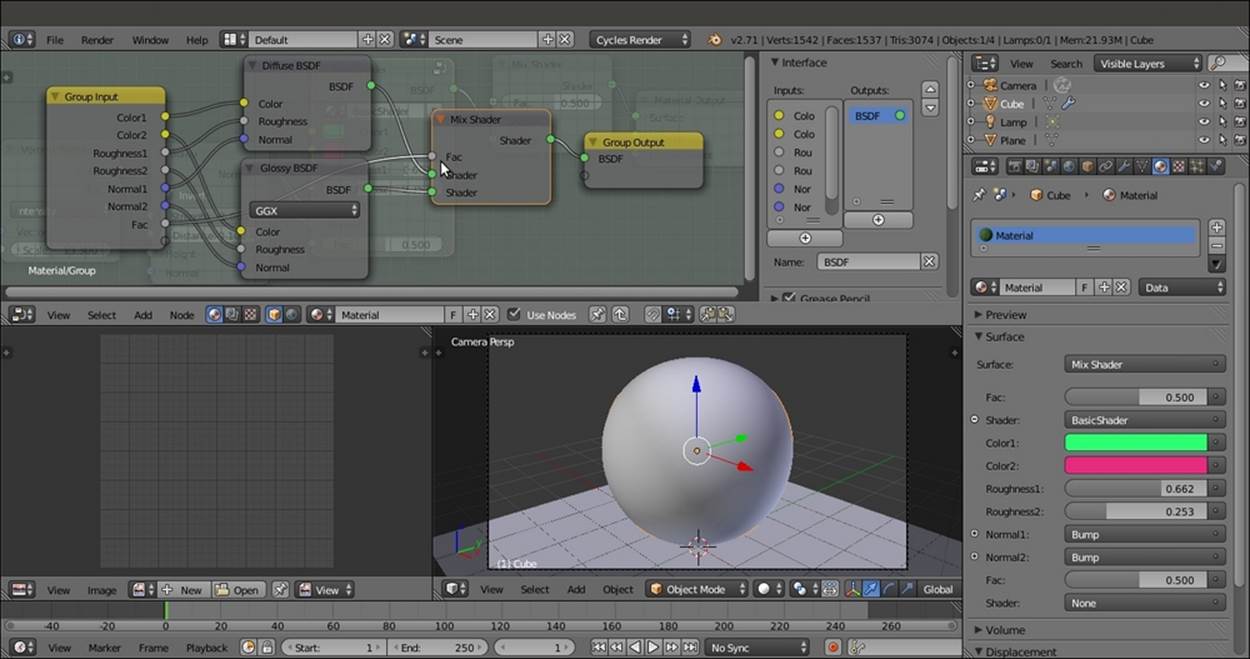
9. Repeat the process to create input sockets for other properties of the Diffuse BSDF and Glossy BSDF nodes. Then press Tab to exit Edit Mode, which is also shown in the following screenshot for your reference:
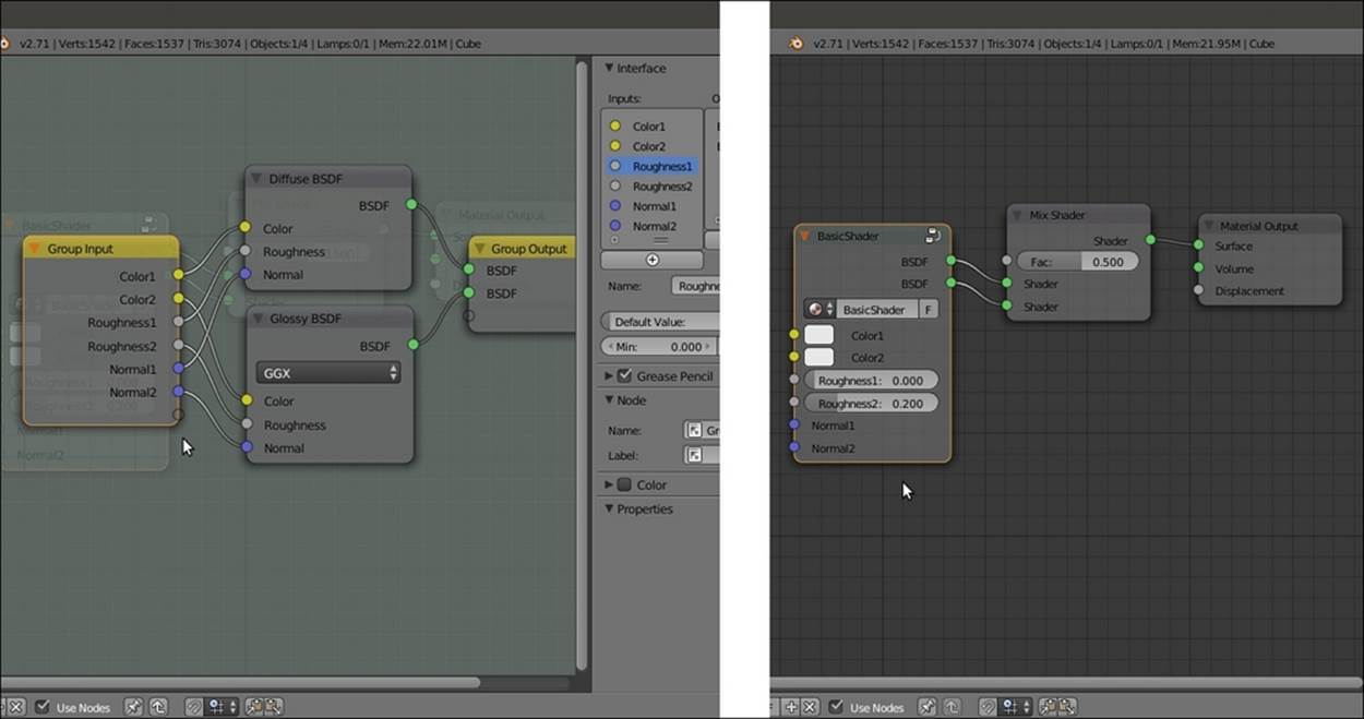
The appearance of the inner connections in the open node group and as exposed input sockets in the closed node group
Here, we get a simple interface for the BasicShader node group, and as you can see in the following screenshot, the exposed values can be tweaked. Also, the properties are driven by textures exactly as in other nodes:
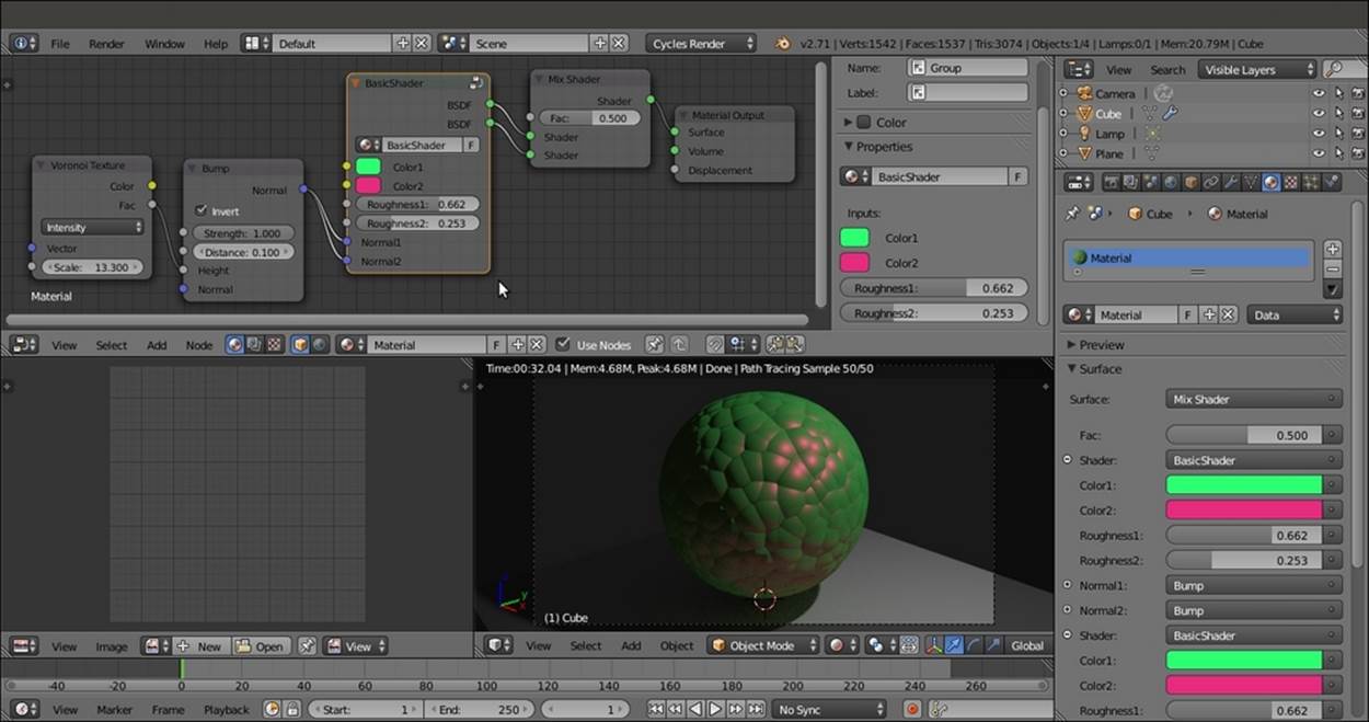
The BasicShader node group put to use
10. Press Tab again to go back to Edit Mode. Move the mouse cursor into the node and press Shift + A to add a Mix Shader node to the group (press Shift + A and navigate to Shader | Mix Shader).
11. Connect the Diffuse BSDF and the Glossy BSDF shaders to the new Mix Shader node and its output to one of the BSDF sockets. Delete the other node by clicking on the X icon in the Properties panel. Connect the empty socket of the Group Input node to the Fac input socket of the Mix Shader node, as shown in this screenshot:
Adding a Mix Shader node inside the node group and one more exposed socket
12. Exit Edit Mode and select the outer Mix Shader node. Press Alt + D (this shortcut removes a node from a network, leaving the connection untouched) to disconnect it and then delete it, or simply press Ctrl + X to delete it, leaving the connection untouched. This is shown in the following screenshot:
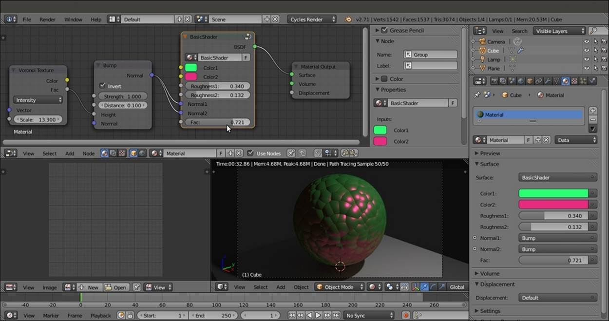
The final interface of the BasicShader node group
How it works...
I think you get the picture. Basically, almost any input or output socket of the nodes wrapped inside a group can be connected to the outside of the node group to be tweaked.
The good thing about a node group is that you can make instances of that node (by pressing Shift + D). Note that when you modify the inner structure of a node group, the modifications get reflected in all the group instances, but the outer (exposed) values on the node group interface are local for each instance and can be individually tweaked.
Every newly created node group is available in both the Add menu (press Shift + A) and in the slots in the Material window of the Properties panel, under the item Group, to be added on the fly to the network.
To remove a node group, select it and press Alt + G. This will break the node envelope but keep the content intact and still connected.
Grouping nodes under frames for easier reading
The shaders we have seen so far are quite simple and easily readable in the Node Editor window, but for several materials we'll see in this Cookbook, the node connections will be a lot more complex and confusing. One more aid we can use to improve the readability of these nodes are the frames. We can use them to visually organize the shaders' network.
Getting ready
Start Blender and open the 9931OS_02_interface.blend file.
How to do it...
Let's see the use of a frame with a simple shader that we already know:
1. Go to the Node Editor window and press Shift + A to add a Frame (press Shift + A and navigate to Layout | Frame). Move the mouse to place its arrow over the nodes, and notice that it always appears to be below them, as shown in the following screenshot:
Adding a Frame to the network inside the Node Editor window
2. Move the mouse cursor to a corner of the frame. It turns into a cross, which means that you can click and drag to resize the corners and the sides of the frame to include the desired nodes as shown in the following screenshot:
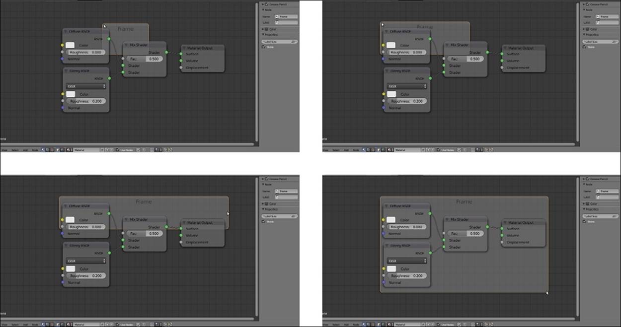
Resizing the Frame to comprise all the nodes
3. Box-select the nodes you want to arrange with the frame (in our case, all of them), then press Shift, and select the frame (or just press A to deselect the frame and box-select everything so that the frame is selected again as the active object). Press Ctrl + P to parent them.
Now that the nodes are parented to the frame, we can select and move it, and all the contained nodes will follow it as a single object.
It's still possible to select the single nodes inside the frames and arrange their individual position and connections. To add a new node to the network, we will do as usual (press Shift + A | …) and then parent it to the frame as well.
4. With the frame still selected, go to the Properties panel to the right of the Node Editor window (Press N if not already present). Just like the case of single nodes, in the Node subpanel, we can change the Name of the frame, assign a Label name visible in the Node Editor window (I wrote BasicShader), and also assign a color.
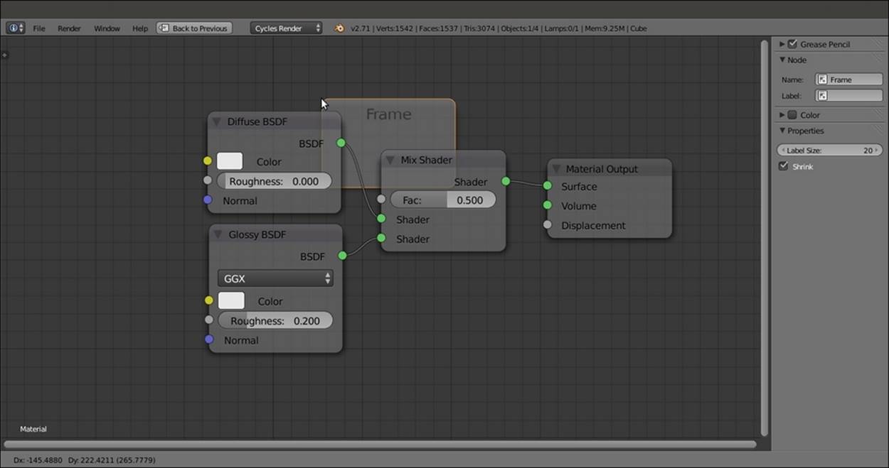
5. In the Properties subpanel right below the Color subpanel, we can change the size of the label name, which is set to 20 by default, and by unchecking the Shrink item, we can freely resize the frame bigger, which otherwise encloses the nodes with a fixed boundary (the default setting), which is shown in the following screenshot for your reference:
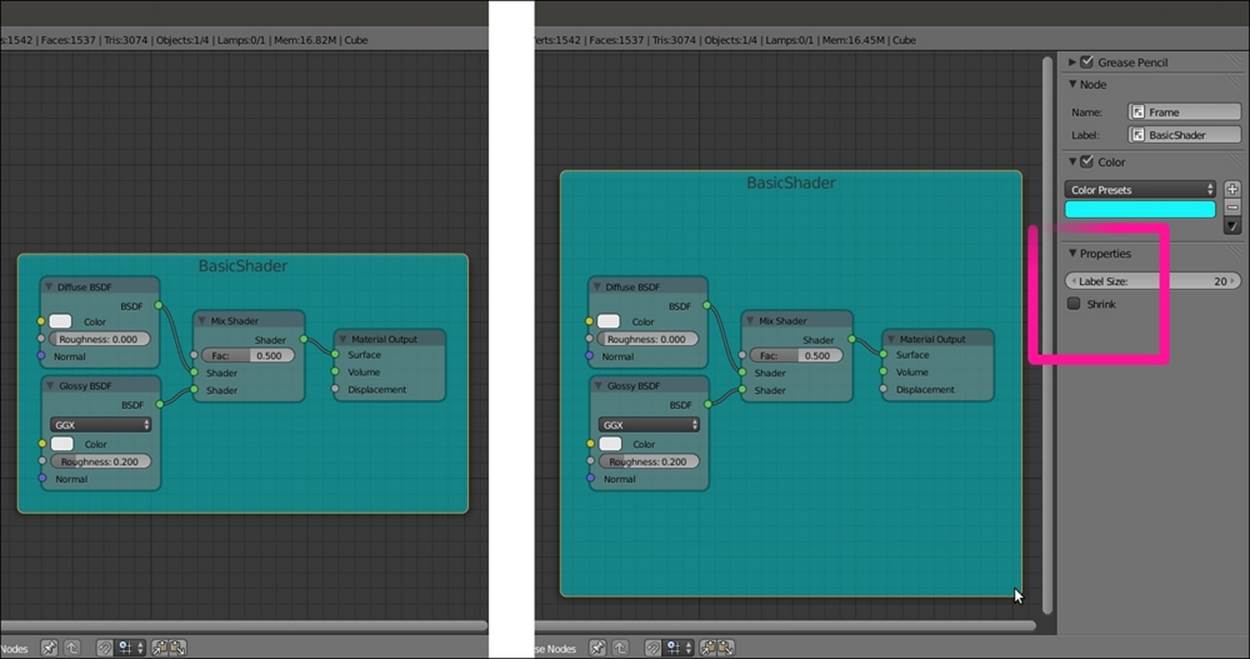
The Frame with label and color
Linking materials and node groups
Similar to Blender Internal, Cycles materials can be linked from libraries. Every blend file containing linkable assets can be a library.
Linking materials is really useful practice. Let's say you have 20 different blend files with objects using an iron shader, and at a certain point of your workflow, you need to modify this iron material in all the files. By having this material linked in all the 20 files from a single blend, it is possible to update all of them at once by modifying just one shader in the library file (as you know, a linked material reflects the properties of the library material and cannot be edited, differently from an appended material that is local to the file where it has been imported from the library file).
How to do it...
Start Blender, go to the File menu in the left part of the main header, and select Link, or press Ctrl + Alt + O. Then perform the following steps:
1. Browse to the directory where you store your library files. Select the blend file you want to link the material from; for example, try the provided 9931OS_02_library.blend file.
2. Browse inside the blend structure, where the linkable assets are divided into subdirectories, shown as folders named Scene, Mesh, Material, NodeTree, Object, and so on. Note that the various folders appear only if the corresponding asset to be linked actually exists inside the blend file.
3. Click on the Material subdirectory. Once inside it, select the material you want to link (for example, Brainy_blue) and press Enter to confirm (or click on the Link/Append from Library button in the top-right corner), as shown in the following screenshot:
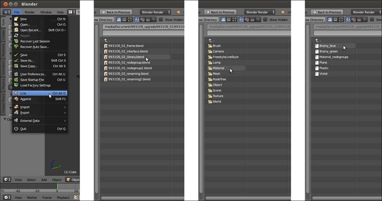
Linking assets through the Blender interface
4. Now click on the Material datablock button on the toolbar of the Node Editor window and select the name of the linked material—the material labeled with a LF prefix; L is for linked and F is for fake user.
5. This is because, in the library file, we assigned the fake user to the material by clicking on the F icon on the side of the material name data block. If not assigned to any fake user, the prefix of the linked material would have been L0, that is, linked and zero fake users inside the blend file (for example, Plane is simply assigned to the object and has no fake user).
The name of the material is grayed to show that it is a linked material. On the side of the name, a new icon has appeared (a little arrow), and the number of users has been updated to 2 (the fake user and the object we assigned the linked material to).
From now on, every modification we make to the material in the library will be reflected in the linked material the moment we load the file.
Not only whole materials but also single node groups can be linked. In this case, instead of the Material subdirectory to link from, choose the NodeTree subdirectory and then select one or more node groups you want to link.
The data block name of a linked node group is grayed as well. You can modify the exposed values and colors, and you can also enter Edit Mode, but that's all. You can't modify the connection or the nodes inside the linked node group. To do this, you have to click on the little arrow icon to the side of the grayed name to make it local and no longer linked from the library file. This would mean that from now on, you have a new independent node group, and that editing the node group in the library won't have any effect on it any more.
There's more...
A very useful add-on to help in node management is the Node Wrangler add-on. It allows for effects such as quick material visualization, node switching, UV layer assignment, frame assignments, node arrangements, and so on. To find out more about this add-on, go to http://wiki.blender.org/index.php/Extensions:2.6/Py/Scripts/Nodes/Node_Wrangler.
To enable it, just call the Blender User Preferences panel (press Ctrl + Alt + U) and click on the Node tab under the Categories item. Enable the Node Wrangler (aka Node Efficiency Tools) add-on by clicking on the checkbox to the right. Then click on the Save User Settings button to the bottom-left corner of the panel.
All materials on the site are licensed Creative Commons Attribution-Sharealike 3.0 Unported CC BY-SA 3.0 & GNU Free Documentation License (GFDL)
If you are the copyright holder of any material contained on our site and intend to remove it, please contact our site administrator for approval.
© 2016-2026 All site design rights belong to S.Y.A.