Blender Cycles: Materials and Textures Cookbook, Third Edition (2015)
Chapter 3. Creating Natural Materials in Cycles
In this chapter, we will cover the following recipes:
· Creating a rock material using image maps
· Creating a rock material using procedural textures
· Creating a sand material using procedural textures
· Creating a simple ground material using procedural textures
· Creating a snow material using procedural textures
· Creating an ice material using procedural textures
Introduction
Replicating nature can be difficult. Natural materials are usually the most difficult to recreate in a satisfying way using computers, mainly because the chaos of nature is not the best fit for the orderly logic of an electronic machine.
Too often, we even see cubes that look obviously computer-generated because of the neatness and regularity of their shapes or surfaces. Actually, in reproducing true to life a natural object (or material as well), we have to start from the absolute regularity of the computer simulation, and then blemish it step by step in a controlled way to reach a more natural look.
Creating a rock material using image maps
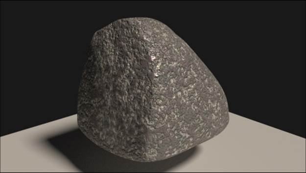
In this recipe, we will create a realistic rock material that looks like the samples shown in the following screenshot, using an image map. We'll see a material made with procedurals in the this recipe.
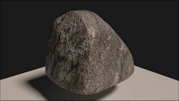
The image-based rock material as it appears in the final rendering
Image maps are particularly useful for several reasons: they already have the necessary color information of a natural surface ready to be used; they can be easily edited in any image editor to obtain different kinds of information, for example, high levels for the bump maps; and they are processed faster than procedurals by the software (procedural textures must be calculated every time). Moreover, they can nowadays be found easily on the Web for free, in several sizes and resolutions.
For our recipe, we'll use the rockcolor_tileable_low.png image map, which you can find in the textures folder provided with this cookbook. This is just a low-resolution texture image provided for the sake of this exercise. Obviously, you can use any other different image with a bigger resolution. Here is a screenshot of the tileable rock image texture for your reference:
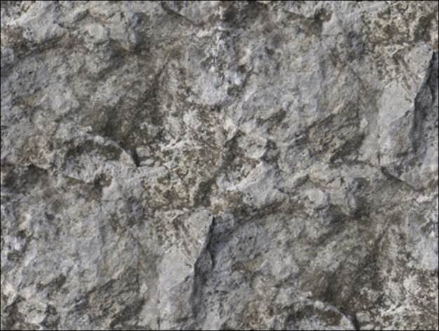
The tileable rock image texture provided with this cookbook
In any case, for any image you are going to use, just remember to make it tileable in your preferred image editor. In GIMP, this task can be automatically done by a plugin that can be found by navigating to Filter | Map | Make Tileable.
Getting ready
Start Blender and load the 9931OS_02_interface.blend file, which saw in the previous chapter. Remember that all the blend files and the textures needed for the exercises of this book can be downloaded from the support page on the Packt Publishing website.
Now, we'll create a new file named 9931OS_start.blend, and we'll be using it as the starting point for the most of our recipes. To do so, perform the following steps:
1. Select the Spheroid and (just for the purpose of this exercise) delete it by pressing X.
2. Ensure that the 3D cursor is at the center of the scene (Shift + C), and with the mouse pointer in the 3D window, press Shift + A to pop up the Add menu. Then add a new Cube primitive (press Shift + A and navigate to Mesh | Cube).
3. Press Tab to go out of Edit Mode if needed (this depends on whether you are using Blender with the factory settings or not), and move the cube 2 units up on the z axis.
4. Go to the Outliner and select the Lamp item, in the Object data window under the Properties panel, switch the Type of Lamp to Sun. Then set the Strength to 2.000 and the color values to 1.000 for R, 0.872 for G, and 0.737 for B.
5. Reselect the Cube, go to the Material window under the Properties panel, and save the file as 9931OS_start.blend.
How to do it...
Now carry out the following steps to create the rock material:
1. Click on the New button in the Material window under the Properties panel, or in the toolbar of the Node Editor window.
2. Rename Material.001 as Rock_01 (the numbering is because I assume that you are going to experiment with several values, especially colors, producing more and different kind of rock materials) and save the file as 9931OS_03_Rock_imagemap.blend.
3. Put the mouse on the Node Editor window and add an Image Texture node (press Shift + A and navigate to Texture | Image Texture). Then add a Mapping node (press Shift + A and navigate to Vector | Mapping), and a Texture Coordinate node (pressShift + A and navigate to Input | Texture Coordinate).
4. Connect the Generated output socket of the Texture Coordinate node to the Vector input socket of the Mapping node, and its Vector output to the Vector input of the Image Texture node. Also connect the Color output of the Image Texture node to theColor input of the Diffuse BSDF shader node.
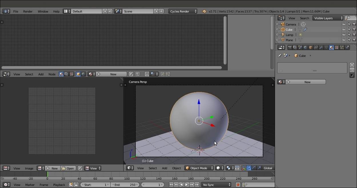
5. Set the Viewport Shading mode of the Camera view to Rendered by pressing Shift + Z with the mouse cursor in the 3D window. The rendered Cube turns pink because there is no image texture loaded yet, as shown in the following screenshot:
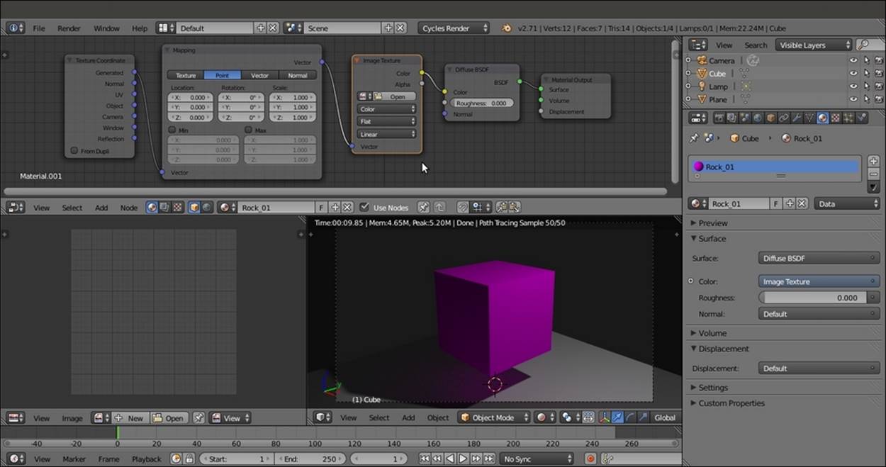
The overall view of Blender's customized Default screen with the rendered preview of the pink Cube
6. Click on the Open button in the Image Texture node, browse to the textures folder, and select the rockcolor_tileable_low.png image.
7. As we selected Generated as the mapping mode, the image is mapped flat on the Cube from the z axis and appears stretched on the sides. Disconnect the Generated output of the Texture Coordinate node and connect the Object node instead. Then click on the Flat button on the Image Texture node to select the Box item. The texture looks now correctly mapped on each face of the Cube, as shown in this screenshot:
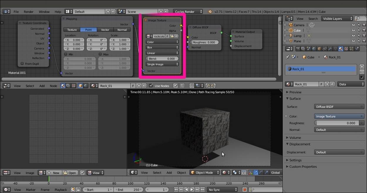
The rock image texture loaded in the Image Texture node
8. Go to the Object modifiers window and assign a Subdivision Surface modifier to the Cube. Set the Subdivisions levels to 4 both for View and Render. Then check the Optimal Display item.
9. Press Shift + Z to go out of the viewport's Rendered mode. Then press Tab to go to Edit Mode and scale all the vertices to double (press Tab, then press S, enter the digit 2, and finally, press Enter). Now, go out of Edit Mode.
10. Press T to make the Tool Shelf panel appear in the Camera view, and click on the Smooth button under the Tools tab. Press T again.
11. Go to the Mapping node in the Node Editor window and set the Scale values for X, Y, and Z to 0.250.
12. Although the image map we used is tileable, there are visible seams at the corners of the subdivided Cube. In the Image Texture node, set Blend factor to 0.200 to soften the seams (this factor is used to blend the edges of the faces of the Cube that, remember, is still a six-faced solid at its lower level, though looks like a Spheroid as of now). The output of blurring effect of the Blend factor is shown in the following screenshot:

The edges seams visible on the surface of the subdivided Cube, and the blurring effect of the Blend factor
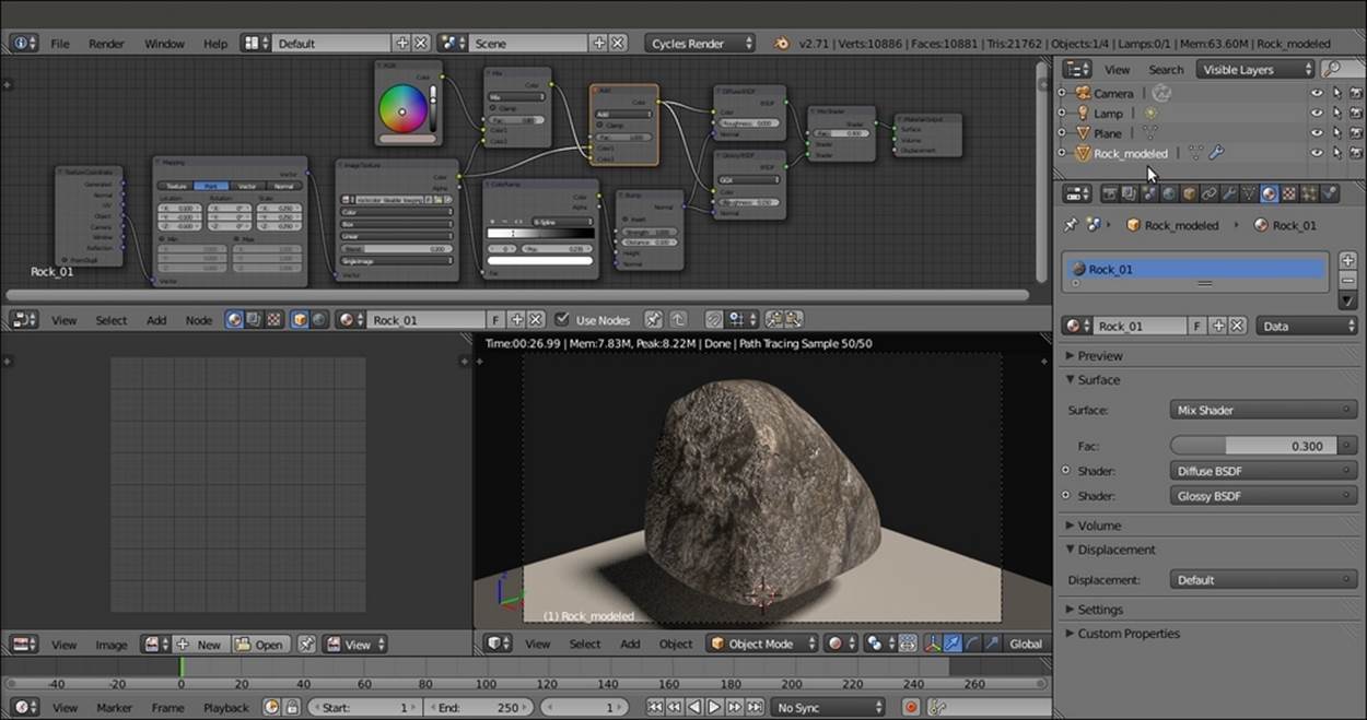
13. Now add a ColorRamp node (press Shift + A and navigate to Converter | ColorRamp) between the Image Texture node and the Diffuse BSDF shader. Set the interpolation to B-Spline, move the marker of the black color to position (Pos:) 0.495 and the white marker to position 0.235, as shown in this screenshot:
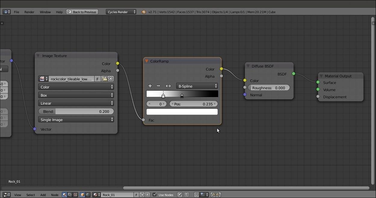
The ColorRamp node pasted between the Image Texture and the Diffuse BSDF nodes
14. Add a Bump node (press Shift + A and navigate to Vector | Bump). Connect the Color output of the ColorRamp to the Height input of the Bump node, and the Normal output of the latter to the Normal input of the Diffuse BSDF shader. Detach the Colorlink from the Color input of the Diffuse BSDF node and leave the Bump node's Strength value to 1.000, as shown in the following screenshot:
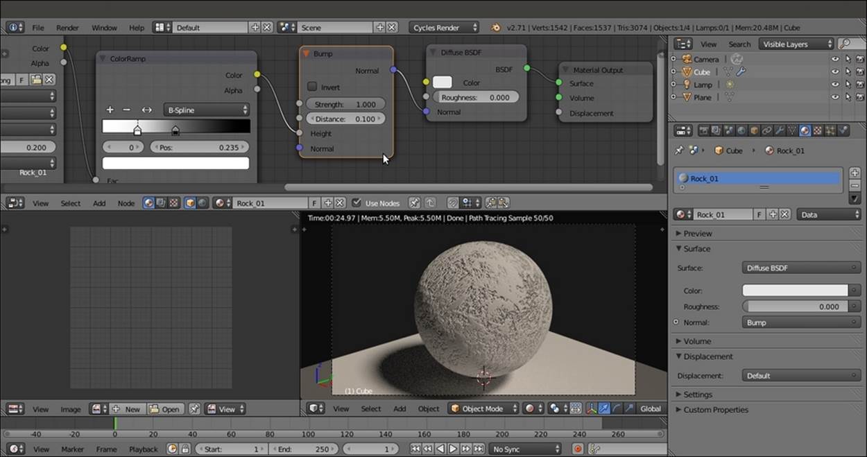
The Bump node pasted between the ColorRamp and Diffuse BSDF nodes
15. Add a Mix Shader node and a Glossy BSDF shader, and connect them to be mixed with the Diffuse BSDF shader. Set the Glossy BSDF node's Roughness value to 0.150 and the Mix Shader node's Fac value to 0.300. Connect the Normal output of theBump node to the Normal input socket of the Glossy BSDF shader, as shown in this screenshot:
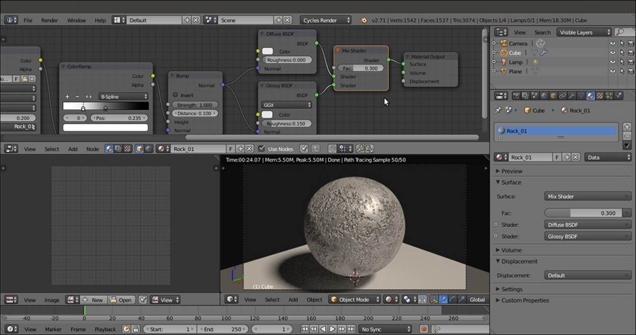
Adding the Mix Shader and the Glossy BSDF nodes
16. Add an RGB node (press Shift + A and navigate to Input | RGB) and a MixRGB node (press Shift + A and navigate to Color | MixRGB). Connect both the Color outputs of the RGB and Image Texture nodes to the Color1 and Color2 input sockets of theMixRGB node. Connect the Color output of the MixRGB node to the Color input sockets of the Diffuse BSDF and Glossy BSDF shaders.
17. Set the Fac value of the MixRGB node to 0.800. Click on the color slider of the RGB node and set the values to 0.407 for R, 0.323 for G, and 0.293 for B, as shown in the following screenshot:
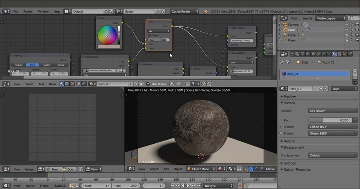
Setting the color for the material
18. Add a new MixRGB node (press Shift + A and navigate to Color | MixRGB). Drag it to be pasted between the first MixRGB node and the Diffuse BSDF shader, and set Blend Type to Add.
19. Connect the Color output of the second MixRGB node (which we can call the Add-MixRGB node) to the Color input socket of the Glossy BSDF shader node, and set its Fac value to 1.000.
20. Connect the Color output of the Image Texture node to the Color1 input socket of the Add-MixRGB node so that the preceding connection coming from the first MixRGB node (which we can call Mix-MixRGB) switches automatically to the Color2 input socket of the Add-MixRGB node, as shown in this screenshot:

Adding more variations to the rock color
21. If you wish, model a very quick rock mesh by sculpting or deforming the subdivided Cube in proportional Edit Mode, and assign to it the Rock_01 material as shown in the following screenshot:
How it works...
We mapped a colored image of a rock with the Box option available in the Image Texture node (developed by the Project Mango team for open movie production of Tears of Steel to quickly map objects without the need to unwrap them), and set the Blend factor to0.200 to have smooth transitions at the corners. Although we had a tileable image texture, this has been necessary because we set the Scale values for the three axes in the Mapping node to 0.250.
First, by connecting the MixRGB node's Color output directly to the Color input of the Diffuse BSDF shader node, we had a quick visual feedback of the image mapping, and thanks to the ColorRamp node, we achieved the following goals:
· We converted the colored image to a gray-scale image to be used for the bump.
· By moving the color markers, we remapped the values of the ColorRamp node's position values to reverse and increase the contrast (we could have obtained the same result by processing the color map in GIMP, for example, by desaturating it and playing with the curve tool). In any case, it's possible to visualize the ColorRamp node itself on the object by temporarily connecting it to the Color input socket of the Diffuse BSDF shader or an Emission shader node connected to the Material Output node.
This contrasted result has been applied as a bump map to both the Diffuse BSDF and Glossy BSDF shaders.
Then we mixed a brownish color (the RGB node) with the Color output of the image of the rock, and the result was added to the Image Texture node's output.
There's more...
We can improve the rocky effect by adding displacement to the geometry. Unlike bump or normal effects on the mesh surface, which are just optical illusions giving an impression of perturbing the mesh surface, displacement is an actual deformation of the mesh based on the gray-scale values of a texture.
At least in this case, there is no need for precise correspondence between the already textured surface and the displacement because it would be barely noticeable. Therefore, we can use object modifiers to obtain a fast but effective result, by performing the following steps:
1. Starting from the Rock_imagemap.blend file we just created, select the Cube and go to the Object modifiers window under the Properties panel. In the Subdivision Surface modifier already assigned, lower the Subdivisions levels for both View and Render to3.
2. Add a new Subdivision Surface modifier and set the levels to 4.
3. Now add a Displace modifier. Click on the Show textures in texture tab button, the last button on the right of the Texture slot. This switches to the Texture window, where we can click on the New button and then change the default Clouds texture to aVoronoi texture node. Set the Size value to 2.00 and leave the rest of the values unchanged. Go back to the Object modifiers window and set the modifier's Strength value to 0.800.
4. Add a new Displace modifier. Switch to the Texture window and assign a new Voronoi Texture node. Change the Size value to 1.20. Back in the modifier, set the Strength value to 0.300.
5. Add one more Displace modifier. This time, we are going to use the default Clouds texture as it is. Just go to the Object modifiers window and set the Strength value to 0.150, as shown in this screenshot:
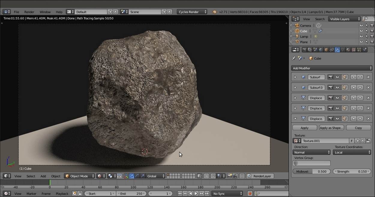
A different rock model, thanks to displacement
Of course, these are just basic values. You can change them and also play with different kinds of procedural textures to obtain several rock shapes.
Creating a rock material using procedural textures
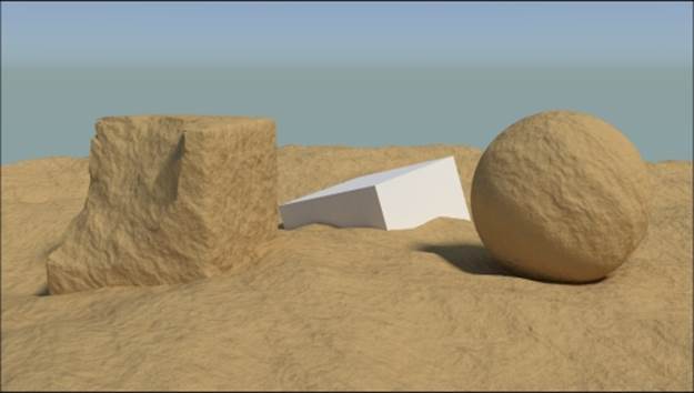
In this recipe, we will try to reach a result similar to the rock material we made through image maps in the previous recipe, but using only procedural textures. The output will look like what is shown in the following screenshot:
The procedural rock material as it appears in the final rendering
Getting ready
Start Blender and load the 9931OS_start.blend file.
1. Select the Cube, go to the Object modifiers window, and assign a Subdivision Surface modifier. Set the Subdivisions levels for View and Render to 4. Go back to the Material window.
2. Press T and in the Tool Shelf, click on the Smooth button under the Shading subpanel. Press T again to get rid of the Tool Shelf.
3. Press Tab to go to Edit Mode. If necessary, select all the vertices by pressing the A key and scale everything to double the current size (press S, enter the digit 2, and press Enter). Go out of Edit Mode.
4. Save the file as 9931OS_start_smoothed.blend. The customized Default screen will now look as shown in the following screenshot:
The customized Default screen with the subdivided Cube
How to do it...
Now we are going to create the rock material by performing the following steps:
1. Select the Spheroid (the smoothed Cube) and click on New in the Material window under the Properties panel or in the Node Editor toolbar. Rename the material Rock_proc_01.
2. In the Node Editor window, add a Noise Texture node (press Shift + A and navigate to Texture | Noise Texture). Then press Shift + D to duplicate it three times. Adjust the four Noise Texture nodes in a column, and in the Properties panel to the right (press N key if it is not already present), label them Noise Texture01, Noise Texture02, Noise Texture03, and Noise Texture04.
3. Add a Texture Coordinate node (press Shift + A and navigate to Input | Texture Coordinate) and a Mapping node (press Shift + A and navigate to Vector | Mapping). Connect the Object output of the Texture Coordinate node to the blue Vector input of the Mapping node. Then connect the Mapping node's Vector output to the Vector input sockets of the four texture nodes. Set the Mapping node's Location values to 0.100 for X and -0.100 for Y and Z, as shown in the following screenshot:
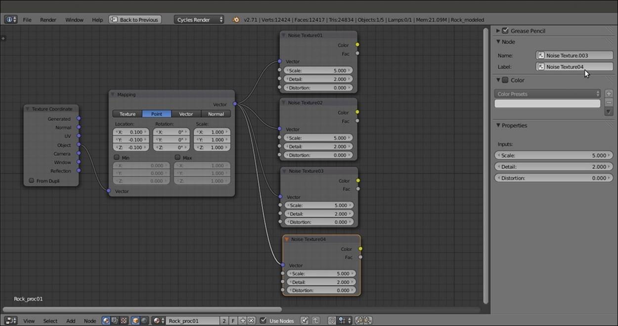
The first steps to build the bump effect for the rock material
4. Add a MixRGB node (press Shift + A and navigate to Color | MixRGB). Connect the first two Noise Texture nodes' Color output to the Color1 and Color2 input of the MixRGB node. Set Blend Type to Overlay and the Fac value to 1.000.
5. Connect the Overlay-MixRGB node's output to the Color input socket of the Diffuse BSDF shader node.
6. Put the mouse cursor in the Camera view and press Shift + Z to set it to Rendered mode.
7. Go to the Noise Texture01 node and set Scale to 4.000 and the Distortion value to 1.400. Then go to the Noise Texture02 node and set Scale to 6.000, Detail to 1.000, and the Distortion value to 0.700.
8. Press Shift + D to duplicate the MixRGB node, and paste it between the Overlay-MixRGB and the Diffuse BSDF nodes. Connect the Color output of the Noise Texture03 node to the Color2 input socket and set the Blend Type to Darken. Go to the Noise Texture03 node, and set Scale to 15.000 and Detail to 3.000.
9. Add a ColorRamp node (press Shift + A and navigate to Converter | ColorRamp) and paste it between the Darken-MixRGB and the Diffuse BSDF nodes. Label it ColorRamp01 and set Interpolation to Ease, the black cursor's position to 0.364, and the white cursor's position to 0.632.
10. Press Shift + D to duplicate the ColorRamp node, and move it close to the Noise Texture04 node. Label the duplicated node ColorRamp02 and set the white cursor's position to 0.340 and the black cursor's position to 0.400.
11. Set the Noise Texture04 node's Scale value to 45.000, Detail value to 0.100, and Distortion to 1.000, as shown in the following screenshot:
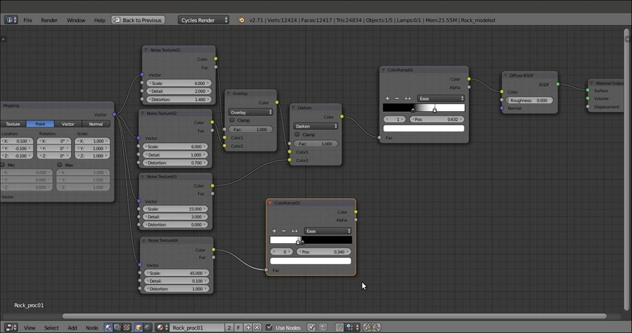
Starting to mix the different procedurals together
12. Connect the Color output of the Noise Texture04 node to the Fac input socket of the ColorRamp02 node. Then add a MixRGB node (press Shift + A and navigate to Color | MixRGB) and label it Mix01.
13. Paste the Mix01 node after the ColorRamp01 node. Then connect the Color output of the ColorRamp02 node to the Color2 input socket of the Mix01 node. Also connect the Fac output of the Noise Texture01 node to the Fac input socket of the Mix01node.
14. Add a new MixRGB node (press Shift + A and navigate to Color | MixRGB) and label it Mix02. Paste it between the ColorRamp02 and the Mix01 nodes.
15. Add a Bump node (press Shift + A and navigate to Vector | Bump) and connect the Color output of the Mix01 node to the Height input socket of the Bump node. Connect the Normal output of the Bump node to the Normal input socket of the Diffuse BSDFshader node. Click on the Invert item checkbox.
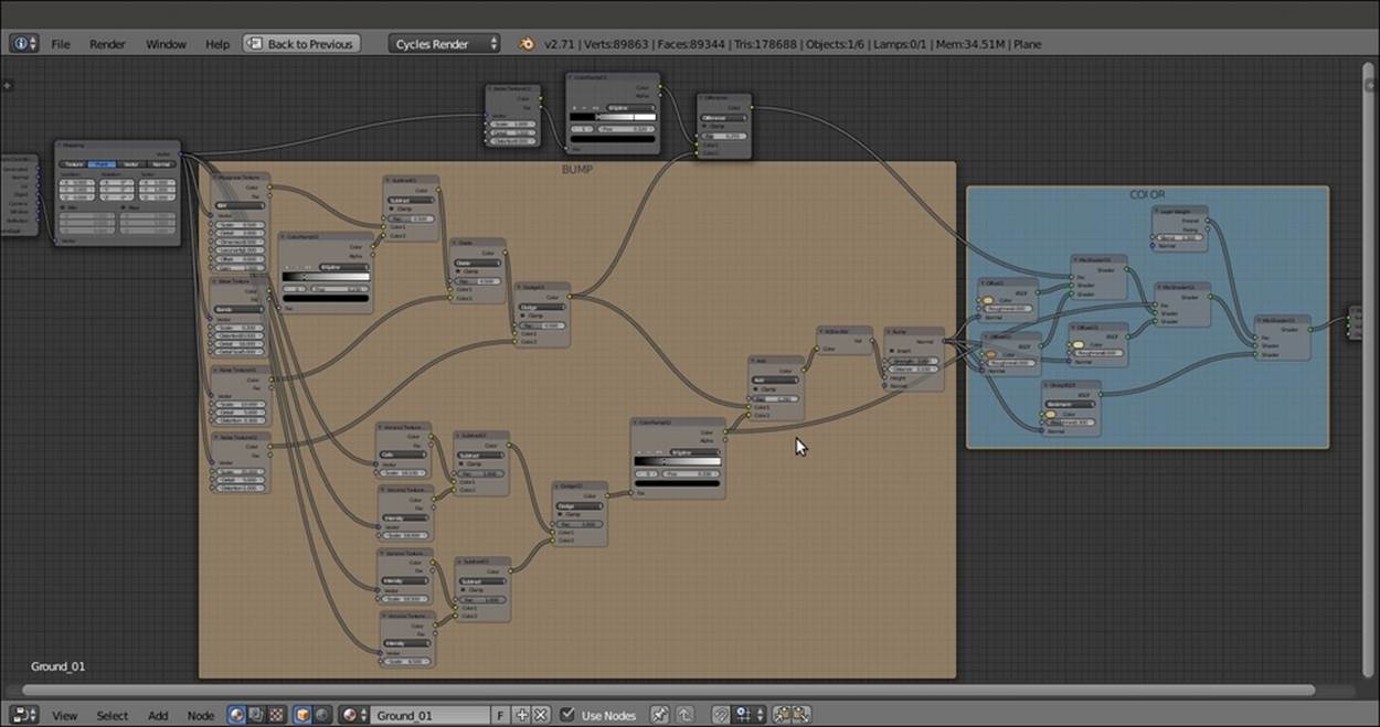
The steps that are detailed after this screenshot will result in the bump effect:
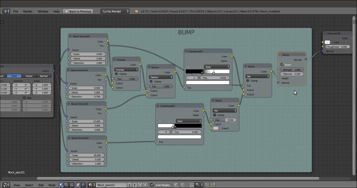
The BUMP frame containing the nodes to build the bump effect
16. Add a Glossy BSDF shader node (press Shift + A and navigate to Shader | Glossy BSDF) and a Mix Shader node (press Shift + A and navigate to Shader | Mix Shader). Paste the Mix Shader node between the Diffuse BSDF and the Material Outputnodes, and connect the Glossy BSDF output to the second Shader input socket.
17. Connect the Normal output of the Bump node to the Normal input socket of the Glossy BSDF shader. Set the Glossy BSDF shader's Roughness to 0.150 and the Fac value of the Mix Shader node to 0.300.
18. Add an RGB node (press Shift + A and navigate to Input | RGB) and connect it to the Color input socket of the Diffuse BSDF shader node. Set the color values to 0.407 for R, 0.323 for G, and 0.293 for B.
19. Add a MixRGB node, label it Mix03, and paste it between the RGB and the Diffuse BSDF nodes. Connect the Color output of the Darken-MixRGB node to the Color2 input socket of the Mix03 node.
20. Add a new MixRGB node. Set Blend Type to Add and the Fac value to 0.800. Connect the Color output of the ColorRamp01 node to the Color1 input socket, and the output of the Mix03 node to the Color2 input socket of the MixRGB node. Connect theColor output of the Add-MixRGB node to the Color input socket of the Diffuse BSDF node.
21. Add an RGB Curves node (press Shift + A and navigate to Color | RGB Curves) and paste it between the Add-MixRGB and the Diffuse BSDF nodes. Connect its output to the Color input socket of the Glossy BSDF shader node.
22. Click on the RGB Curves node's little window to create a new point. Set its position values to 0.24545 for X and 0.38125 for Y. Then create another point and set the position values to 0.74545 for X and 0.51875 for Y, as shown in the following screenshot:
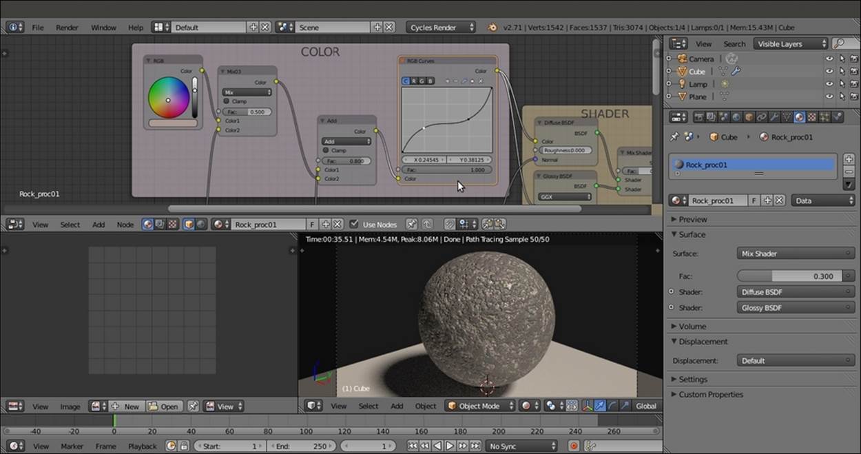
Screenshot of the COLOR frame connected to the Diffuse and Glossy shaders
How it works...
Even if this material looks a bit complex at first sight, you must note that we just mixed four procedural noise textures with different settings and iterations to build the bump effect and create the color pattern to some extent:
· In the first stage, from steps 2 to 15, we built the bump pattern by mixing the output of the noise textures (the Overlay, Darken, Mix01, and Mix02 nodes converging to the input socket of the Bump node) through MixRGB nodes, and in some cases also edited their levels using the ColorRamp nodes to obtain a more random, natural look (ColorRamp1 and ColorRamp2, all the nodes inside the BUMP frame).
· In the second stage, from steps 18 to 22, we built the color pattern by mixing a simple color output with the output of some of the Noise Texture nodes, and then edited the result using an RGB Curves node (nodes inside the COLOR frame).
· The results of both the bump and the color patterns were then piped into the appropriate sockets of the nodes inside the SHADER frame, that is, the Diffuse BSDF node was mixed with the Glossy BSDF node to add specularity (steps 16 and 17). The overall material network in the Node Editor window is shown in the following screenshot:
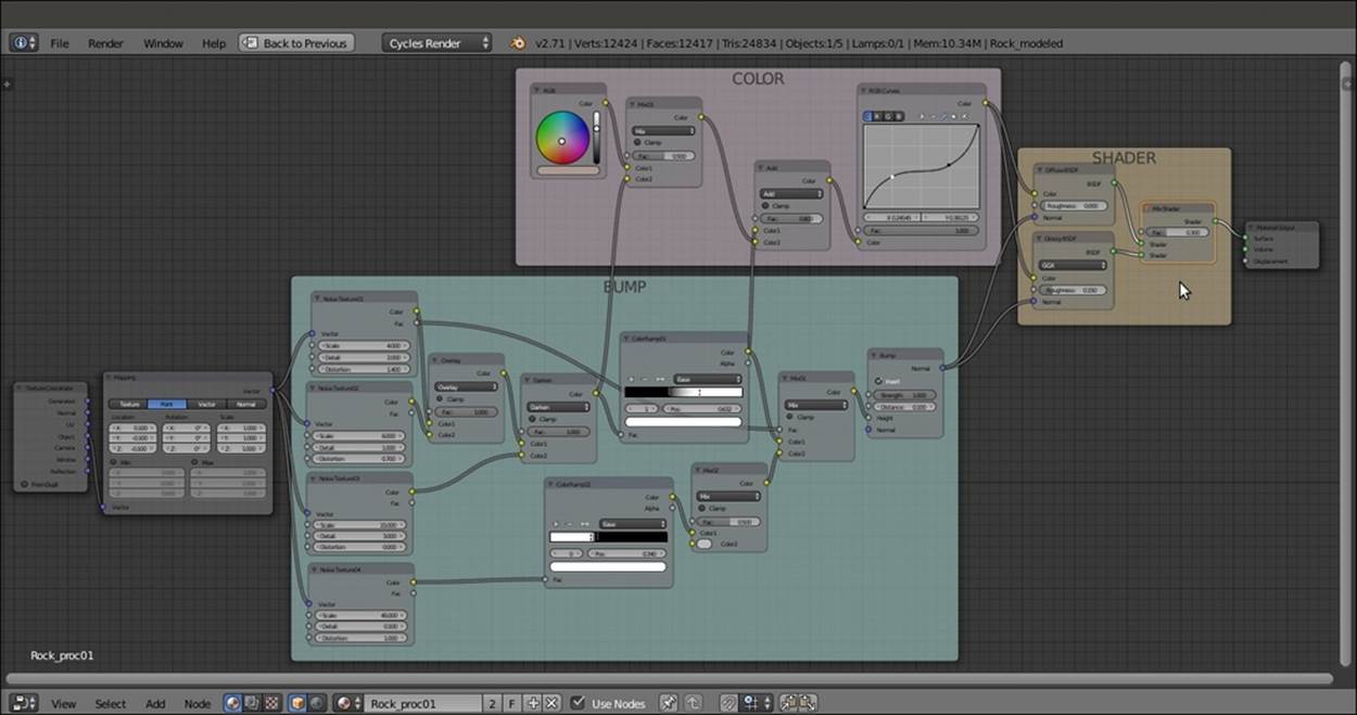
The overall vision of the material network
Creating a sand material using procedural textures
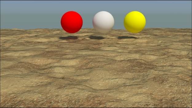
In this recipe, we will create a sand material that looks like what is shown in the following screenshot, which is good for both close and distant objects:
The sand material as it appears in the final rendering
Getting ready
Start Blender and switch to the Cycles Render engine. Then perform the following steps:
1. Delete the default Cube and add a Plane (press Shift + A and navigate to Mesh | Plane).
2. Press Tab to go to Edit Mode and scale it nine times bigger, with 18 units per side (press S, enter the digit 9, and press Enter). Go out of Edit Mode.
3. Go to the World window and click on the Use Nodes button under the Surface subpanel in the Properties panel to the right of the screen. Then click on the little square with a dot on the right side of the Color slot. Select the Sky Texture item from the pop-up menu. Set the Strength value to 1.900.
4. Select the Lamp, go to the Object data window, and click on the Use Nodes button. Then change the Type of Lamp to Sun and set Strength to 3.000. Change the color values to 1.000 for R, 0.935 for G, and 0.810 for B. In orthogonal top view, rotate the Sunlamp by 45°, as shown in the following screenshot:
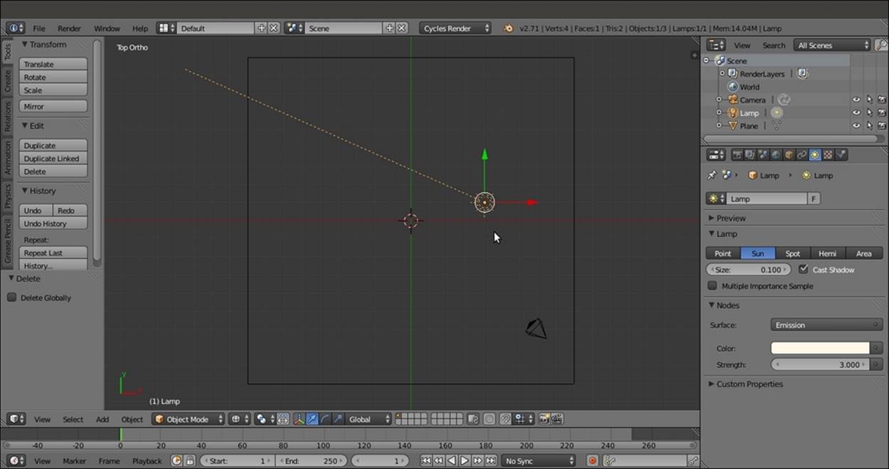
The scene from the top with the Sun Lamp selected
5. Add a Cube and a UV Sphere to the scene and place them leaning on the Plane.
6. Select the Cube and click on the Smooth button in the Shading subpanel under the Tools tab to the left of the 3D window (press the T key to make it appear if it is not present).
7. Select the UV Sphere and perform the same actions as given in step 6.
8. Select the Cube, and in the Object modifiers window, add a Bevel modifier. Set Width to 0.1000, Segments to 2, and Profile to 0.15. Assign a Subdivision Surface modifier, set both the Subdivisions levels to 4, and check the Optimal Display item. Assign a Smooth modifier and set Factor to 1.000 and Repeat to 15.
9. Select the UV Sphere and assign a Subdivision Surface modifier with Subdivisions levels set to 2 and the usual Optimal Display item checked.
10. Select the Plane, click on the Smooth button, and then go to Edit Mode and press W. In the Specials pop-up menu, select the Subdivide item. Press the F6 key to call the Options pop-up menu (or go to the panel at the bottom of the Tool Shelf tabs) and set Number of Cuts to 10.
11. Go out of Edit Mode, go to the Object modifiers window, and assign a Subdivision Surface modifier. Switch to the Simple subdivision algorithm and set both Subdivisions to 3. Check the Optimal Display item.
12. Assign a Displace modifier and then click on the Show texture in texture tab button to the side of the New button. In the Texture window, click on the New button and switch the default Clouds texture with the Voronoi texture. Set the Size value to 5.00.
13. Assign a new Displace modifier, click on the Show texture in texture tab button, and load a Voronoi texture again. Leave the Size value at 0.25.
14. Assign a Smooth modifier and set Factor to 1.000 and the Repeat value to 5.
15. Place the Camera to have a nice angle on the Plane and switch from the 3D view to a Camera view (by pressing the 0 key on the numeric keypad).
16. Split the 3D window into two horizontal rows and change the upper row to a Node Editor window. Put the mouse cursor in the 3D view and press Shift + Z to set the Camera view mode to Rendered.
17. Go to the Render window. Under the Sampling subpanel, set both the Clamp Direct and Clamp Indirect values to 1.000. Go to the Light Path subpanel and set the Filter Glossy value to 1.000.
18. Set the Render samples to 25. The Rendered preview is shown in the following screenshot for your reference:
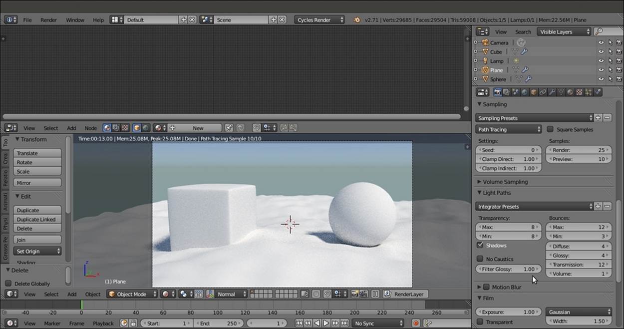
The prepared scene as it appears in the Rendered preview, with the rendering settings to the right
How to do it...
We have prepared the scene. Now let's start with the creation of the sand material using the following steps:
1. Select the Plane and click on the New button in the Material window under the Properties panel or in the Node Editor toolbar. Rename the material Sand_01.
2. Keeping the Shift key pressed, select the UV Sphere, the Cube, and for last one, the Plane (that is the active object of the multi-selection) by right-clicking on them. Press Ctrl + L, and in the Make Links pop-up menu, select the Material item to assign the same material to the other two objects. The Sand_01 material is now assigned to all three objects.
3. In the Material window under the Properties panel to the right, switch the Diffuse BSDF shader with a Mix Shader node. In both the Shader slots, assign a Diffuse BSDF shader.
4. In the Node Editor, add an RGB node (press Shift + A and navigate to Input | RGB) and an RGB Curves node (press Shift + A and navigate to Color | RGB Curves). Connect the output of the RGB node to the Color input socket of the first Diffuse BSDFshader and to the Color input socket of the RGB Curves node. Then connect the output of the RGB Curves node to the Color input socket of the second Diffuse BSDF shader node.
5. Change the color values of the RGB node to 0.500 for R, 0.331 for G, and 0.143 for B. Click on the RGB Curves node window to create a new point, and set the coordinates to 0.48182 for X and 0.56875 for Y.
6. Add a Noise Texture node (press Shift + A and navigate to Texture | Noise Texture), a Texture Coordinate node (press Shift + A and navigate to Input | Texture Coordinate), and a Mapping node (press Shift + A and navigate to Vector | Mapping).
7. Connect the Object output of the Texture Coordinate node to the Vector input of the Mapping node, and then connect the Vector output to the Vector input of the Noise Texture node.
8. Connect the Fac output of the Noise Texture node to the Fac input of the Mix Shader node. Increase the Detail value of the texture to 5.000.
9. Press Shift + D to duplicate the Mix Shader node and paste it between the first Mix Shader node and the Material Output node. Add a Glossy BSDF shader node (press Shift + A and navigate to Shader | Glossy BSDF), set its Roughness to 0.700, and connect its output to the second Shader input socket of the second Mix Shader node. Set the Fac value to 0.100.
10. Connect the Color output of the RGB node to the Color input socket of the Glossy BSDF shader node.
11. Add a Frame (press Shift + A and navigate to Layout | Frame), press Shift and multi-select the RGB node, the RGB Curves node, the Noise Texture node, the two Diffuse BSDF nodes, the Glossy BSDF shader, the two Mix Shader nodes, and the Frame, and press Ctrl + P to parent them. In the Properties panel (press N key in the Node Editor window), label the Frame as SAND COLOR, as shown in the following screenshot:
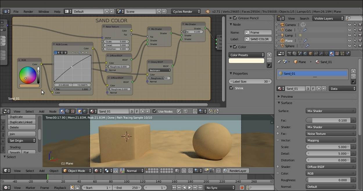
The total vision of the SAND COLOR frame and the rendered effect on the objects
12. Add a new Noise Texture node and a Wave Texture node (press Shift + A and navigate to Texture | ...). Select both and press Shift + D to duplicate them. Label them Wave Texture01, Wave Texture02, Noise Texture01, and Noise Texture02.
13. Arrange the four texture nodes in a column like this: Wave Texture01, Noise Texture01, Noise Texture02, and Wave Texture02. Connect the Mapping output to the texture nodes' Vector input.
14. Set the Scale value of Wave Texture01 to 3.000, Distortion to 25.000, and Detail to 10.000. Set the Detail value of Noise Texture01 to 10.000 and Distortion to 0.500. Set the Detail value of Noise Texture02 to 10.000 as well. Finally, set the Wave Texture02node's Scale value to 25.000, Distortion to 15.000, and Detail Scale value to 5.000.
15. Add a MixRGB node (press Shift + A and Color | MixRGB) and label it Mix01. Connect the Wave Texture01 node's Color output to the Color1 input and the Noise Texture01 node's Color output to the Color2 input.
16. Select the MixRGB node and press Shift + D to duplicate it. Label it Mix02 and connect the Color output of the Mix01 node to the Color1 input of the Mix02 node. Then connect the Wave Texture02 node's Color output to its Color2 input.
17. Connect the Color output of the Noise Texture02 node to the Fac input socket of the Mix02 node. Now the Node Editor window looks like what is shown in the following screenshot:
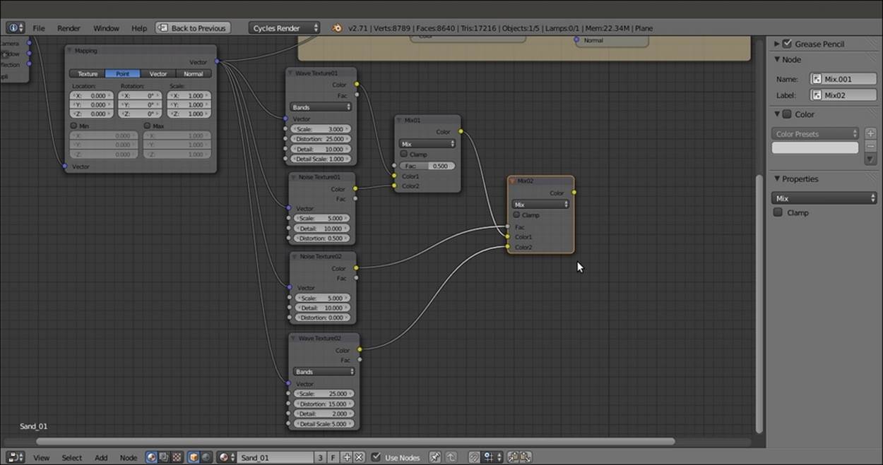
Building the bump pattern
18. Add a Math node (press Shift + A and navigate to Converter | Math) and label it Bump_Strength. Change Operation to Multiply and connect the output of the Mix02 node to the first Value input socket. Set the second Value input socket's value to 1.000 and connect the node output to the Displacement input socket of the Material Output node, as shown in this screenshot:
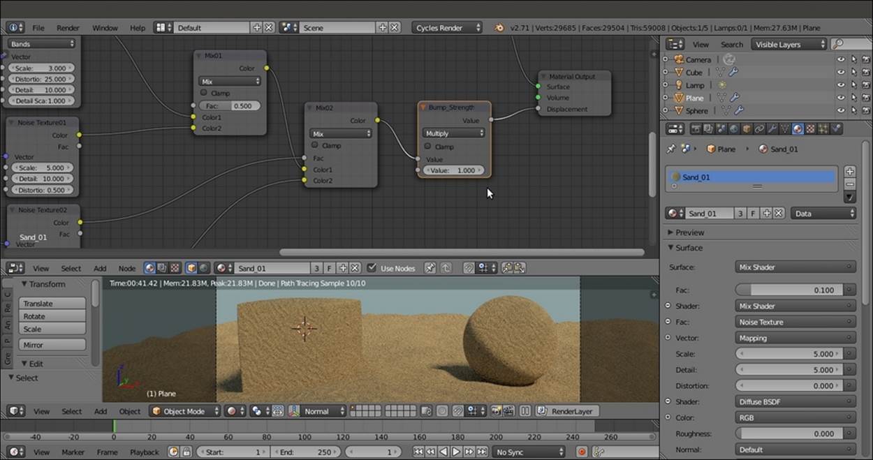
The effect of the total output of the bump nodes connected to the Displacement input of the Material Output node
19. Add a Hue/Saturation node (press Shift + A and navigate to Color | Hue/Saturation), label it Hue Saturation Value01, and drag it onto the link connecting the Noise Texture01 node to the Mix01 node to paste it in between. Set Value to 10.000.
20. Press Shift + D to duplicate the Hue/Saturation node, label the duplicate Hue Saturation Value02, and drag it onto the link connecting the Wave Texture02 node to the Mix02 node. Set Value to 0.100.
21. Press Shift + D to duplicate it again, name the duplicate Hue Saturation Value03, and drag it between the Mix02 node and the Bump Strength node. Set Value to 0.350. The following screenshot shows the effect of adding variation to the bump:
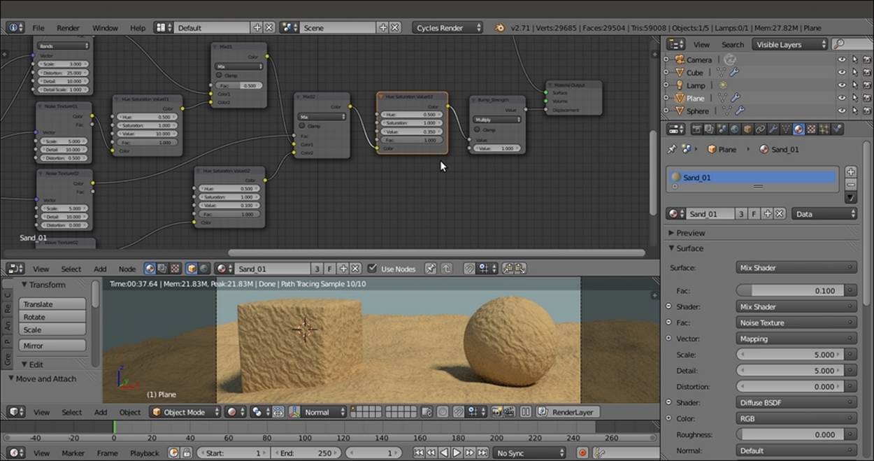
Adding variation to the bump pattern
22. Add a Bright/Contrast node (press Shift + A and navigate to Color | Bright Contrast). Drag it so that it's pasted between the Noise Texture02 node and the Mix02 factor input. Set the Bright value to -0.250 and the Contrast value to 1.000.
23. Add a Frame, press Shift (or box-select (press B key) these 11 nodes and then the Frame), and press Ctrl + P to parent them. Label the Frame SAND BUMP, as shown in the following screenshot:
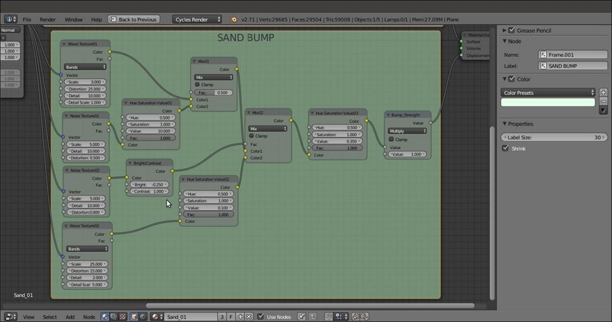
The SAND BUMP frame containing all the bump nodes
24. Select the Wave Texture02 node and press Shift + D to duplicate it twice (if the node is still parented to the SAND BUMP frame after duplication, press Alt + P to unparent it). Label them Wave Texture03 and Wave Texture04. Then duplicate the Bright/Contrastnode twice and name the duplicates Bright/Contrast02 and Bright/Contrast03.
25. Select one of the MixRGB nodes and press Shift + D to duplicate it. Set Blend Type (and the label) to Divide and the Factor to 1.000.
26. Connect the Mapping vector output to the Vector input sockets of the two new wave textures.
27. Connect each Color output of the two new wave textures to the respective Color input of the Bright/Contrast02 nodes. Then connect their color output to the Color1 and Color2 input of the Divide node.
28. In the Wave Texture03 node, set Scale to 0.500, Distortion to 25.000, Detail to 10.000, and Detail Scale to 1.000. In the Bright/Contrast02 node, set the Bright value to 0.000 and the Contrast value to -0.800.
29. In the Wave Texture04 node, set Scale to 1.000, Distortion to 10.000, Detail to 5.000, and Detail Scale to 1.000. In the respective Bright/Contrast03 node, set the Bright value to 0.000 and the Contrast value to -0.800.
30. Add a Math node (press Shift + A and navigate to Converter | Math). Set Operation to Multiply, label it Multiply01, and leave the first Value as it is—the same as the Scale value of the Wave Texture03 node (0.500). Set the second Value to 1.000. Connect the Value output to the Scale input socket of the Wave Texture03 node.
31. Press Shift + D to duplicate the Math node (label it Multiply02). Move it to the side of the Wave Texture04 node and set the first Value to be the same as the Scale value of the texture node (1.000). Set the second Value to 1.000 as well, and connect the Valueoutput to the Scale input of the Wave Texture04 node.
32. Add a Value node (press Shift + A and navigate to Input | Value). Connect the output to the second Value input sockets of both the Multiply-Math nodes. Label it Waves_size and set the input value to 1.000.
33. Add a Frame, parent the last added nodes, and label it BIG WAVES, as shown in the following screenshot:
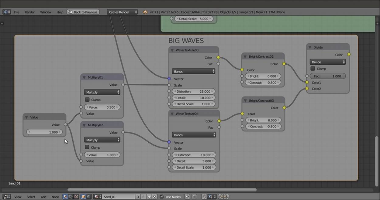
A new frame containing a new bump effect to be added to the previous one
34. Duplicate the Bump_Strength node, unparent it from the SAND BUMP node, and set the Operation to Add. Drag it onto the link between the Bump_Strength node and the Material Output node, and label it Add_Bump01.
35. Connect the Divide node output of BIG WAVES to the second Value input socket of the Add_Bump01 node, as shown in this screenshot:
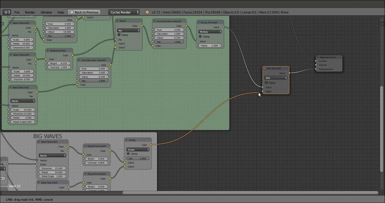
The output of the two bump frames added together
36. Duplicate a Noise Texture node (label it Noise Texture03), a Bright/Contrast node (label it Bright/Contrast04), and a Math node (label it Grain_Strength). Connect the Mapping output to the Vector input of the texture node. Then connect the Noise Texturenode's Color output to the Bright/Contrast04 node's Color input and its output to the first Value input socket of the Grain_Strength node. Set its operation to Multiply and the second Value to 0.250.
37. Set the texture Scale to 200.000, Detail to 1.000, and Distortion to 0.000. Set the Bright/Contrast04 node's Bright value to 0.000 and Contrast to 0.200.
38. Add a Frame, parent the three nodes to it, and label it GRANULARITY, as shown in the following screenshot:
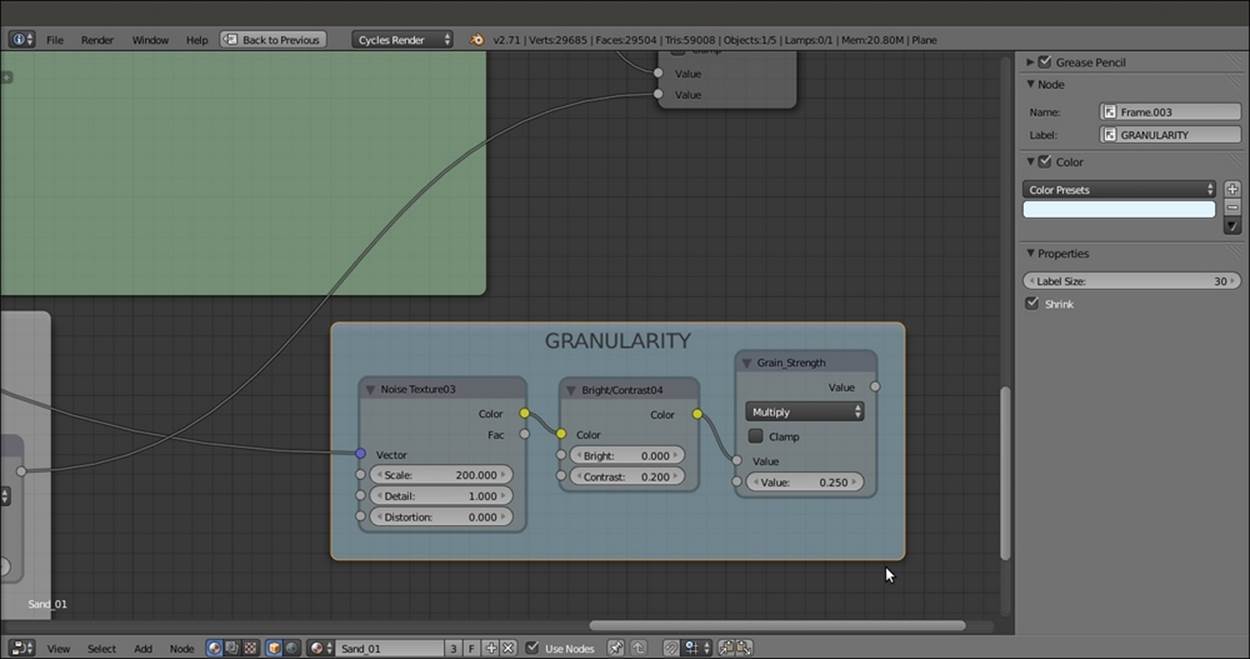
One more bump effect frame
39. Duplicate the Add_Bump01 node, and label it Add_Bump02, and paste it between the Add_Bump01 node and the Material Output node. Connect the Grain_Strength output of the GRANULARITY frame to the second Value input socket of the Add_Bump02node.
40. Duplicate the Add_Bump02 node and paste it just before the Material Output node. label it TOTAL BUMP STRENGTH, set the node Operation to Multiply, and set the second Value to 0.500, as shown in this screenshot:
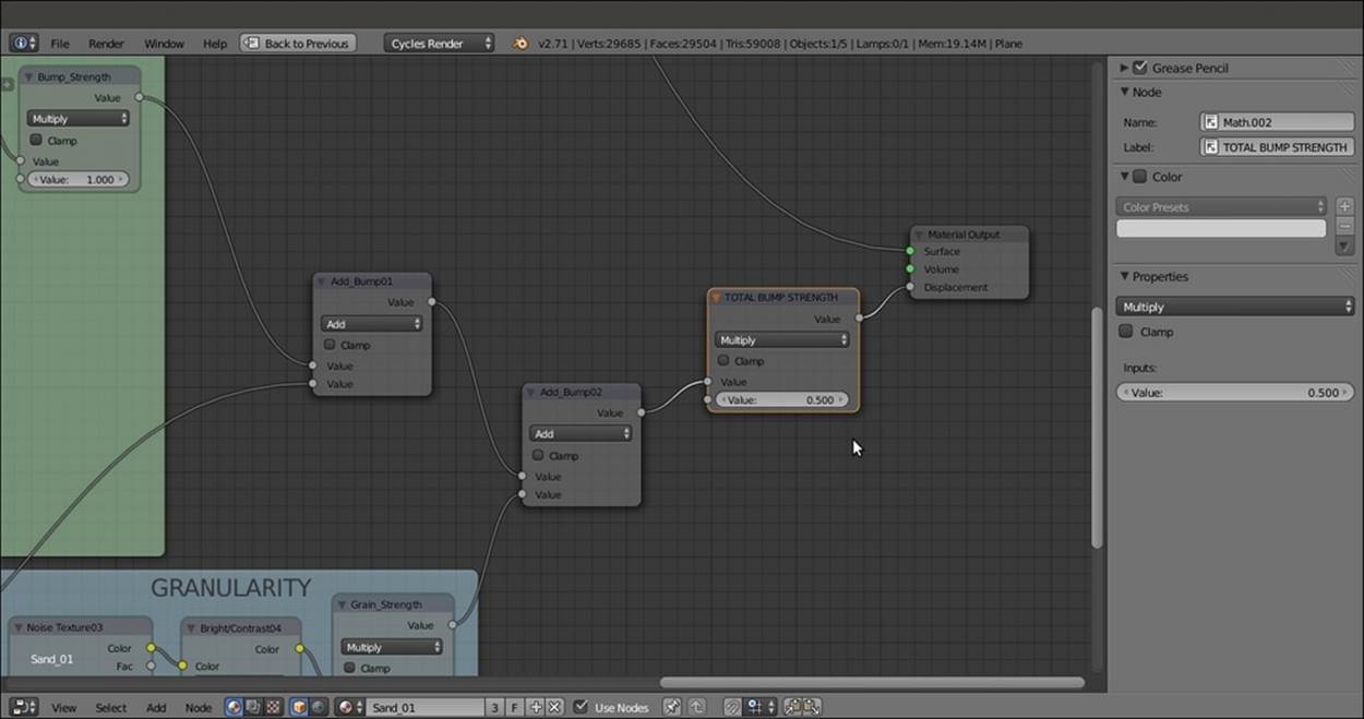
The GRANULARITY frame output added to the previous bump ones
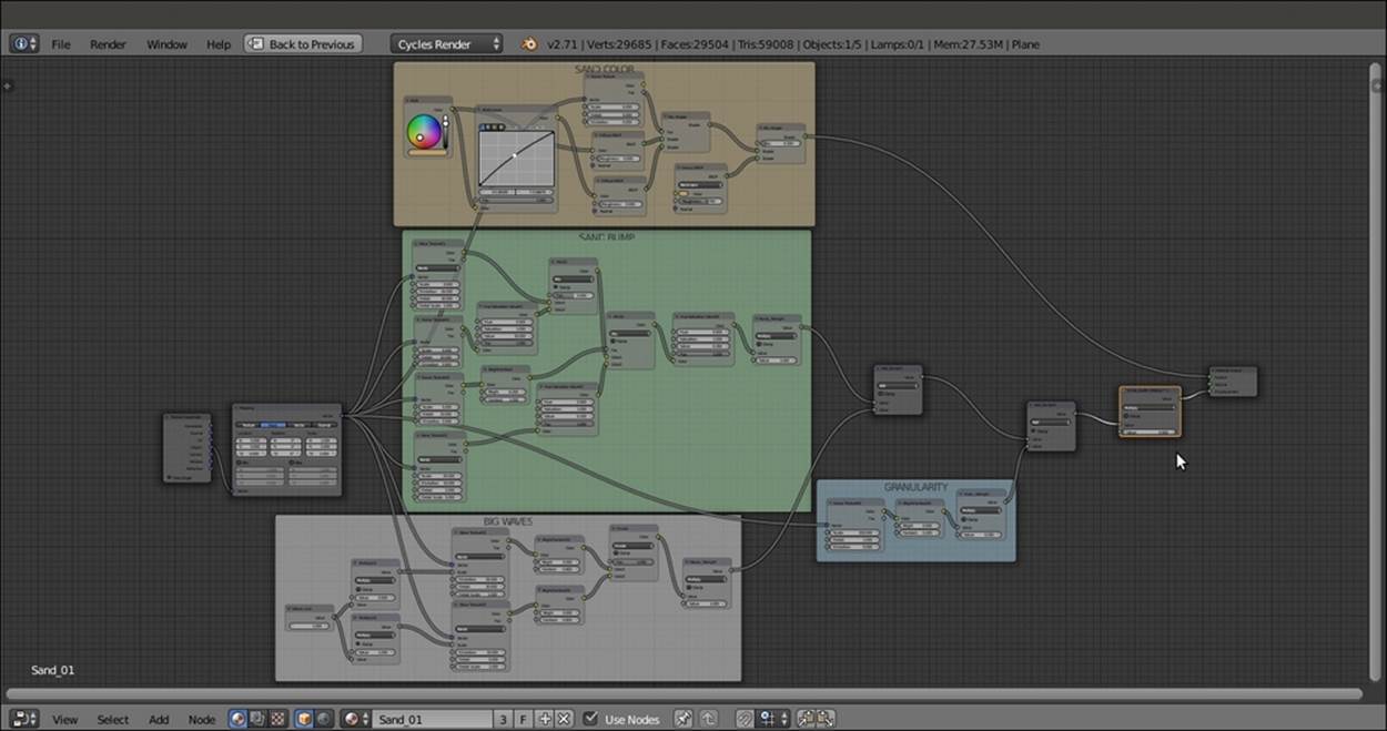
So here we are now—the sand shader is complete, and this is how the nodes' network looks in the Node Editor window:
To obtain the image shown at the beginning of this recipe, we also added a few elements to the scene:
· A new Cube primitive, with a simple diffuse pure white material, added just for reference to light intensity.
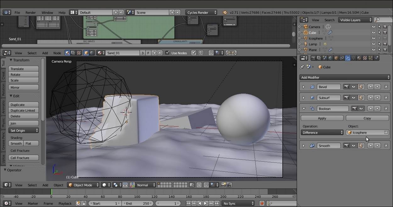
· An Ico Sphere primitive, set as invisible and disabled for the rendering in Outliner. It works as target Object for a Boolean modifier assigned to the sand Cube and is placed in the stack between the Subdivision Surface and Smooth modifiers, as shown in the following screenshot:
How it works...
The concept behind the structure of this material is basically the same as that for the procedural rock, and it can be subdivided into stages as well:
· From step 1 to step 10, we built the color part of the shader, blending two differently colored Diffuse BSDF nodes on the ground of a Noise Texture factor, and building a basic shader with the Glossy BSDF component.
· From step 12 to step 22, we built the main bump effect, this time piped directly as whole in the Displacement input of the Material Output node rather than to the Normal input sockets per shader.
· From step 24 to step 32, we built a supplementary bump effect, this time to simulate the big waves you usually see on a desert's sand dunes. This effect was left apart from the main bump to be easily reduced or eliminated if required. Then we added twoMath nodes set to Multiply and driven by a Value node to automatically set the size of the big sand waves. Actually, this is more a repeating effect, and the bigger the value, the smaller and closer the waves.
· In steps 36 and 37, we built a last bump effect to add the sand grain if necessary, for example, for objects very close to the camera. In steps 39 and 40, we summed all the bump effects, to be driven by the last Math node value.
Every stage has been framed and properly labeled to make it more easily readable in the Node Editor window.
There's more...
One more thing we can do to improve this material is combine everything into a handy group node, at the same time leaving the fundamental values to be tweaked exposed on the node group interface. To do this follow these steps:
1. Put the mouse cursor in the Node Editor window and press the B key. Two horizontal and a vertical lines appear at the location of the mouse cursor. Click and drag the mouse to encompass the framed nodes, leaving outside only the Texture Coordinatenode, the Mapping node, and the Material Output nodes. After the mouse button is released, everything you encompassed is selected.
2. Press Ctrl + G and create the group. Then press N in the Node Editor window to call the Properties panel on the right side.
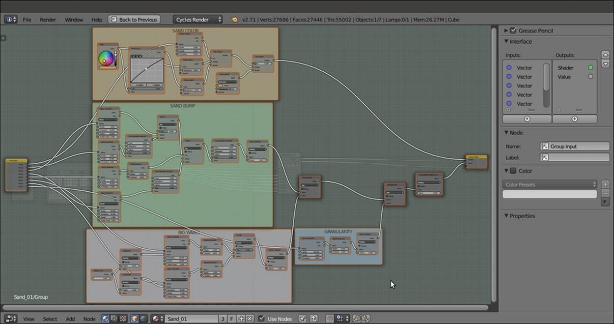
The previous sand material network inside a node group
3. Press Tab to go out of Edit Mode. Then click on the little window on the interface to change the name from NodeGroup to Sand_Group.
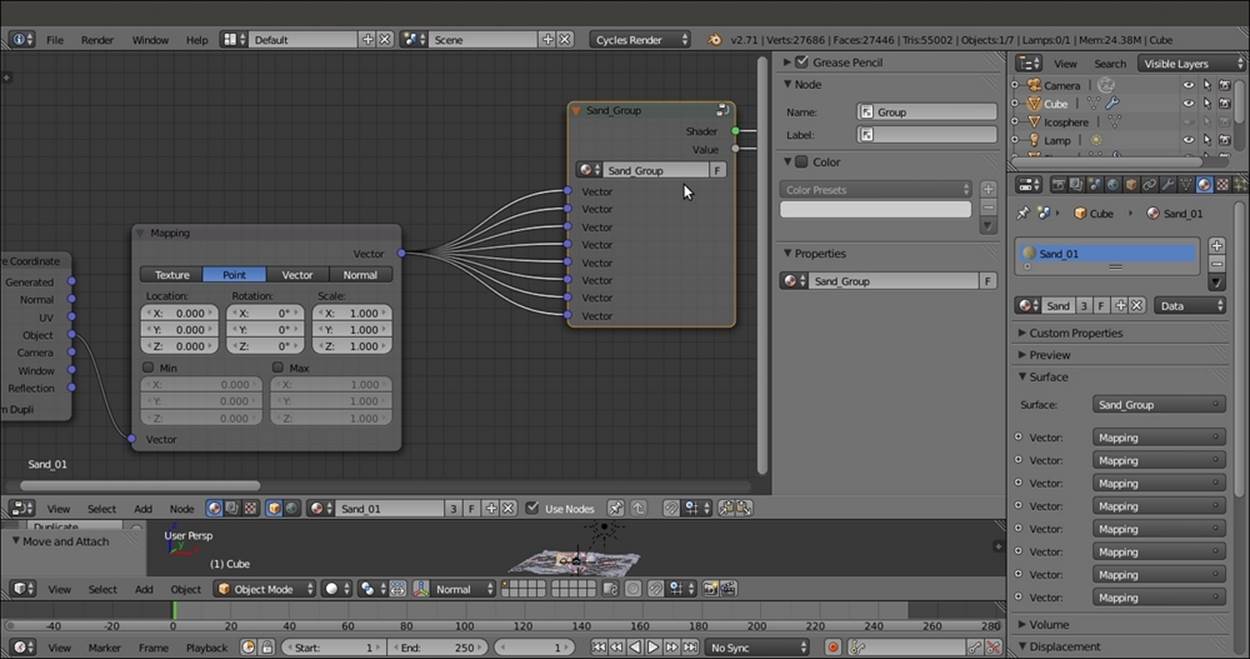
The closed node group
As you can see, inside the group, the Group Input node collects all the Vector sockets from which the various texture nodes take their mapping coordinates, so we now have eight Vector sockets in the outer interface, all connected to the same Object output of theMapping node. However, we need only one Vector input to map all the textures inside the group, so let's perform the following steps:
1. Press Tab to go to Edit Mode again and deselect everything by pressing the A key.
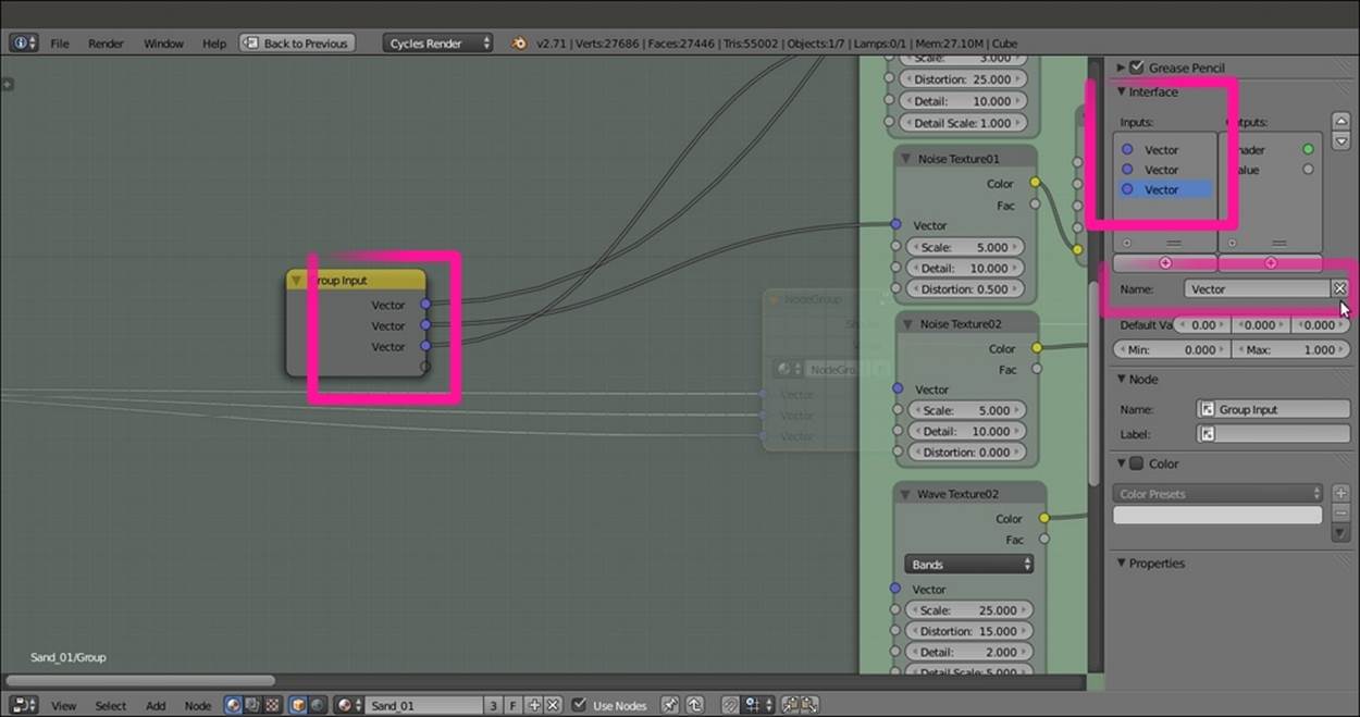
2. Select the first bottom Vector output by clicking on the list of names in the little Inputs window under the Properties/Interface panel. Delete the corresponding Vector socket from the Group Input node by clicking on the X icon to the side of the newly appeared Name slot. Then click on the X icon again, and go on like this to delete all the Vector sockets except the last socket at the top of the list as shown in the following screenshot:
3. Now press Shift, select the Group Input node and the first texture node, and press F to automatically connect them.
4. Repeat to connect all the eight texture nodes to the Vector socket of the Group Input node.
Now we need to expose some of the values to modify the material from the interface, so let's perform the following steps:
1. From the second Value socket of the Bump_Strength node inside the SAND BUMP frame, click and drag a link to the bottom free socket in the Group Input node. In the Input window under the Properties panel, double-click on the newly appeared input socket name, Value, and write Sand_strength.
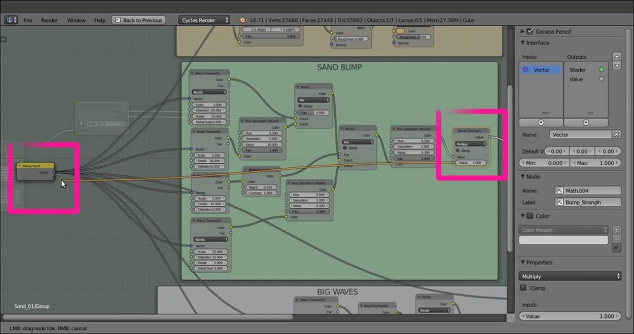
All the Vector input sockets of the nodes are connected to a single socket on the Group Input node, and the Bump Strength value is exposed by a new connection
2. Repeat step 1 for the second Value socket of the Waves_Strength and the Grain_Strength nodes, and rename the respective input as Waves_strength and Granularity.
3. Now click on the Waves_size node inside the BIG WAVES frame and delete it. Click and drag the second Value socket of the Multiply01 node to the Group Input node, and rename the new socket Waves_size. Click and drag a link from the second Valuesocket of the Multiply02 node, and connect it to the Waves_size socket as well.
4. We also need to expose the second Value socket of the TOTAL BUMP STRENGTH frame. Rename the new socket on the interface as Total strength. This is in fact the value for the overall bump of the material.
5. After this, we can do the following: expose the color input by deleting the RGB node in the SAND COLOR frame and connecting the Color input sockets of the Diffuse BSDF, RGB Curves, and Glossy BSDF shader node's to the Color socket on the Group Input node; expose the sand's grain size value, connecting the Scale input socket of the Noise Texture03 node to a Grain_size socket; and finally, by clicking on the arrows in the Properties panel, order the position of the input sockets on the Group Inputnode as shown in this screenshot:
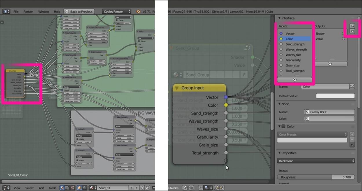
The sockets created on the Group Input node and reflected in the Interface subpanel
6. Press Tab to close the group. On the interface, we now have the controls to increase or decrease the overall bump effect, the sand color and grain, the wave strength, and scale/repetition, as we can see in the following screenshot:
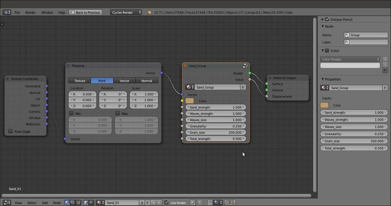
The final Sand_Group node with all the exposed input on its interface
The group is now available under the Add menu, and its shortcut involves pressing Shift + A and navigating to Group | Sand_Group. It can be reused for other materials in the same scene and also with different interface values, or linked/appended from a library in other blend files.
Creating a simple ground material using procedural textures
In this recipe, we will create a basic, raw ground material as shown in this screenshot:
The ground material as it appears in the final rendering
Getting ready
Start Blender and switch to Cycles Render. Then perform the following steps:
1. Delete the default Cube and add a Plane. Go to Edit Mode and scale it 15 times bigger (30 units per side; press Tab, then press S, enter the digit 15, and press Enter). Go out of Edit Mode.
2. Go to the Object modifiers window and assign a Subdivision Surface modifier to the Plane. Switch from Catmull-Clark to Simple, and set the levels of Subdivisions for both View and Render to 4. Check the Optimal Display item.
3. Assign a second Subdivision Surface modifier. Again, switch to Simple, set the levels of Subdivisions for both View and Render to 4, and check the Optimal Display item.
4. Assign a Displace modifier. Click on the Show texture in texture tab button to the side of the New button. In the Texture window, click on the New button, select Voronoi texture, and increase the Size value to 1.80. Go back to the Object modifiers window and set the displacement Strength to 0.100.
5. Assign a second Displace modifier and select the default Clouds texture. Set the Size value to 0.75, the Depth value to 5, and the displacement Strength value to 0.150.
6. Assign a third Displace modifier. Again, select the default Clouds texture and increase the Size value to 4.00 (the slider arrives at a maximum of 2.00, but you can click on the value and enter higher values) and the Depth value to 4. Then switch Noise fromSoft to Hard and click on the Basis button to change Noise Basis from Blender Original to Voronoi F4. Go to the Colors subpanel above the Clouds subpanel, and adjust the Brightness value to 0.900 and the Contrast value to 1.500. Set the displacement strength to 0.500.
7. In the Shading subpanel (which is accessible from the Transform menu), under the Tool Shelf tabs to the left of the 3D view, click on the Smooth button.
8. Go to the World window and click on the Use Nodes button in the Surface subpanel under the Properties panel. Then click on the little square with a dot on the right side of the Color slot. From the menu, select Sky Texture. Set the Strength value to 1.400.
9. Go to the Outliner and select the Lamp item. Go to the Object data window and click on Use Nodes. Then change Type of Lamp to Sun and set the Strength value to 1.400. Change the light color values to 1.000 for R, 0.935 for G, and 0.810 for B. In the orthogonal top view (press the 7 and 5 keys in the numeric keypad), rotate the Sun Lamp by 90°.
10. Place the Camera to have a nice angle on the Plane (you can also use the Lock Camera to View item in the (press N) Properties side panel), and switch from the 3D view to the Camera view (by pressing 0 from the numeric keypad).
11. Split the 3D window into two horizontal rows. Change the upper row to a Node Editor window.
12. Go to the Render window, and under the Sampling subpanel, set both the Clamp Direct and Clamp Indirect values to 1.000. Go to the Light Path subpanel and set the Filter Glossy value to 1.000.
13. Reselect the Plane and go to the Material window under the Properties panel. Disable the transformation widget by clicking on the icon in the 3D window toolbar or by pressing Ctrl and the spacebar, as shown in the following screenshot:
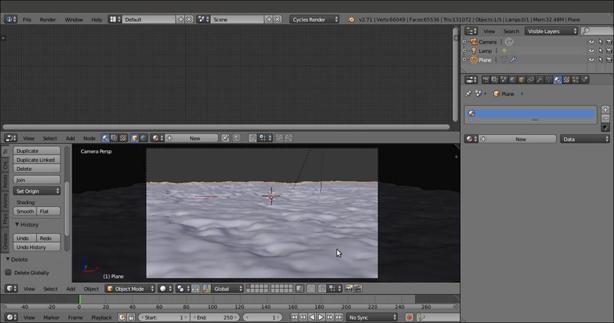
Screenshot in the Solid viewport shading mode of the ground scene
In the final scene, I added three UV Spheres with simple diffuse colors, just for lighting reference. Obviously, you can skip this step.
How to do it...
Let's now start with the ground material:
1. Put the mouse cursor in the Camera view and press Shift + Z to switch the Viewport Shading mode to Rendered.
2. Click on the New button in the Material window or in the Node Editor toolbar. Rename the material Ground_01.
3. In the Node Editor window, add a Texture Coordinate node (press Shift + A and navigate to Input | Texture Coordinate), a Mapping node (press Shift + A and navigate to Vector | Mapping), and a Musgrave Texture node (press Shift + A and navigate toTexture | Musgrave Texture).
4. Connect the Object output of the Texture Coordinate node to the Vector input of the Mapping node and the Vector output of this node to the Vector input of the Musgrave Texture node.
5. Connect the Color output of the Musgrave Texture node to the Color input of the Diffuse BSDF shader. In the Properties panel, label the Diffuse BSDF shader as Diffuse01. Set the Scale value of the Musgrave Texture node to 0.500.
6. Add a Wave Texture node (press Shift + A and navigate to Texture | Wave Texture) and a MixRGB node (press Shift + A and navigate to Color | MixRGB). Paste the MixRGB node between the Musgrave Texture node and the Diffuse01 shader node, and connect the Wave Texture node's color output to the Color2 input socket of the MixRGB node.
7. Set the MixRGB node's Blend Type to Subtract and label it Subtract01. Connect the Mapping output to the Wave Texture node's Vector input.
8. Set the Wave Texture node's Scale value to 0.200, Distortion to 20.000, Detail to 16.000, and Detail Scale to 5.000.
9. Add a ColorRamp node (press Shift + A and navigate to Converter | ColorRamp) and drag it onto the link connecting the Wave Texture node to the Subtract01 node to paste it between them. Label it ColorRamp01, change the Interpolation mode to B-Spline, and move the black stop to the 0.230 position (Pos:).
10. Add two Noise Texture nodes (press Shift + A, navigate to Texture | Noise Texture, and then press Shift + D to duplicate it) and name them Noise Texture01 and Noise Texture02. Connect the Mapping node to them. Select the Subtract01 node, press Shift +D to duplicate it twice, and change Blend Type to Divide and Dodge. Connect the Color output of the Subtract01 node to the Color1 input of the Divide node, and connect the Color output of the Noise Texture01 node to the Color2 input of the Dividenode.
11. Then connect the Color output of the Divide node to the Color1 input of the Dodge node, and the Color output of the Noise Texture02 node to the Color2 input of the Dodge node.
12. Label the Dodge node Dodge01 and connect its output to the Color input of the Diffuse01 shader. Set the Noise Texture01 scale to 10.000, Detail to 5.000, and Distortion to 0.300. For Noise Texture02, set Scale to 35.000, Detail to 5.000, and Distortion to1.000, as shown in the following screenshot:
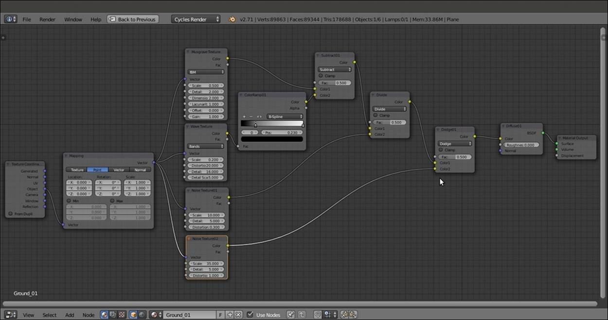
The first steps to build the bump effect for the ground material
13. Add two Voronoi Texture nodes (press Shift + A, navigate to Texture | Voronoi Texture, and rename the nodes Voronoi Texture01 and Voronoi Texture02) and a new MixRGB node (press Shift + A and navigate to Color | MixRGB). Set the Blend Type toSubtract and label it Subtract02. Connect the color output of the Voronoi Texture01 node to the Color1 input socket, and the color output of the Voronoi Texture02 node to the Color2 input socket.
14. Set the Subtract02 node's Fac value to 1.000, and then go to the Voronoi Texture01 node. Set Coloring to Cells and Scale to 18.100. Go to the Voronoi Texture02 node, leave Coloring as Intensity, and set the Scale value to 18.000.
15. Select the two Voronoi Texture nodes and the Subtract02 node, and press Shift + D to duplicate them. Label the texture nodes as Voronoi Texture03 and Voronoi Texture04, and the MixRGB node as Subtract03.
16. Connect the Mapping node output to the Vector input sockets of the four Voronoi Texture nodes.
17. Change the Coloring of the Voronoi Texture03 node back to Intensity, and set the Scale value to 18.500. Set the Scale value of Voronoi Texture04 to 6.500.
18. Add a new MixRGB node (press Shift + A and navigate to Color | MixRGB) and change the Blend Type to Dodge. Label it Dodge02 and set the Fac value to 1.000. Connect the output of the Subtract02 node to the Color1 input socket and the output of theSubtract03 node to the Color2 input socket.
19. Add a MixRGB node again (press Shift + A and navigate to Color | MixRGB). Change the Blend Type to Add and paste it between the Dodge01 node and the Diffuse01 shader node. Then connect the output of the Dodge02 node to the Color2 input socket.
20. Disconnect the link between the Add output and the Color input socket of the Diffuse01 shader node, and add a Bump node (press Shift + A and navigate to Vector | Bump). Connect the output of the Add node to the Height input socket of the Bump node. Then connect the Normal output of the Bump node to the Normal input socket of the Diffuse01 shader. Set the Add node's Fac value to 0.280 and the Bump node's Strength value to 0.800.
21. Add a ColorRamp node (press Shift + A and navigate to Converter | ColorRamp) and label it ColorRamp02. Paste it between the Dodge02 and the Add nodes. Set Interpolation to B-Spline and move the black color slider and stop at position 0.330.
22. Add a RGB to BW node (press Shift + A and navigate to Converter | RGB to BW) and paste it between the Add and the Bump nodes.
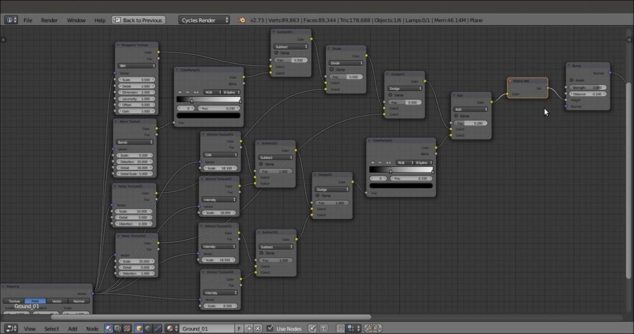
The total BUMP network for the ground material
23. Parent the nodes to a Frame (press Shift + A and navigate to Layout | Frame) and label it BUMP, as shown in the following screenshot:
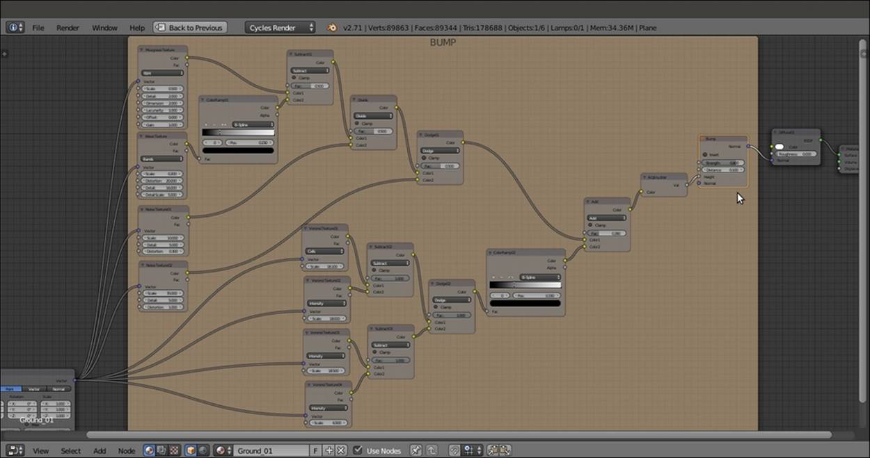
The BUMP frame
24. Add a Mix Shader node (press Shift + A and navigate to Shader | Mix Shader) and a second Diffuse BSDF shader (press Shift + A and navigate to Shader | Diffuse BSDF). Name them Mix Shader01 and Diffuse02, respectively. Then paste the Mix Shader01node between the Diffuse01 and the Material Output nodes, and connect the Diffuse02 node to the second Shader input socket of the Mix Shader01 node.
25. Once again, add a Mix Shader node (press Shift + A and navigate to Shader | Mix Shader) and a Diffuse BSDF shader (press Shift + A and navigate to Shader | Diffuse BSDF). Label them Mix Shader02 and Diffuse03. Then paste the Mix Shader02 node between the Mix Shader01 node and the Material Output node, and connect the Diffuse03 node to the second Shader input socket.
26. Connect the Bump node output to the Normal input of the Diffuse02 and Diffuse03 shader nodes.
27. Change the Diffuse01 color values to 0.593 for R, 0.460 for G, and 0.198 for B; the Diffuse02 color values to 0.423 for R, 0.234 for G, and 0.092 for B; and the Diffuse03 color values to 0.700 for R, 0.620 for G, and 0.329 for B.
28. Once more, add a Mix Shader node (press Shift + A and navigate to Shader | Mix Shader) and a Glossy BSDF shader (press Shift + A and navigate to Shader | Glossy BSDF). Label the first node Mix Shader03 and paste it between the Mix Shader02 and the Material Output nodes. Connect the Glossy BSDF shader to the second Shader input socket of the Mix Shader03 node, and set its Roughness value to 0.300 and the color values to 0.593 for R, 0.460 for G, and 0.198 for B, just like the Diffuse01 color.
29. Connect the Bump node output to the Normal input socket of the Glossy BSDF node.
30. Add a Layer Weight node (press Shift + A and navigate to Input | Layer Weight), connect the Fresnel output to the Fac input socket of the Mix Shader03 node, and set the Blend value to 0.300.
31. Parent these recently added nodes to a new Frame and label it COLOR.
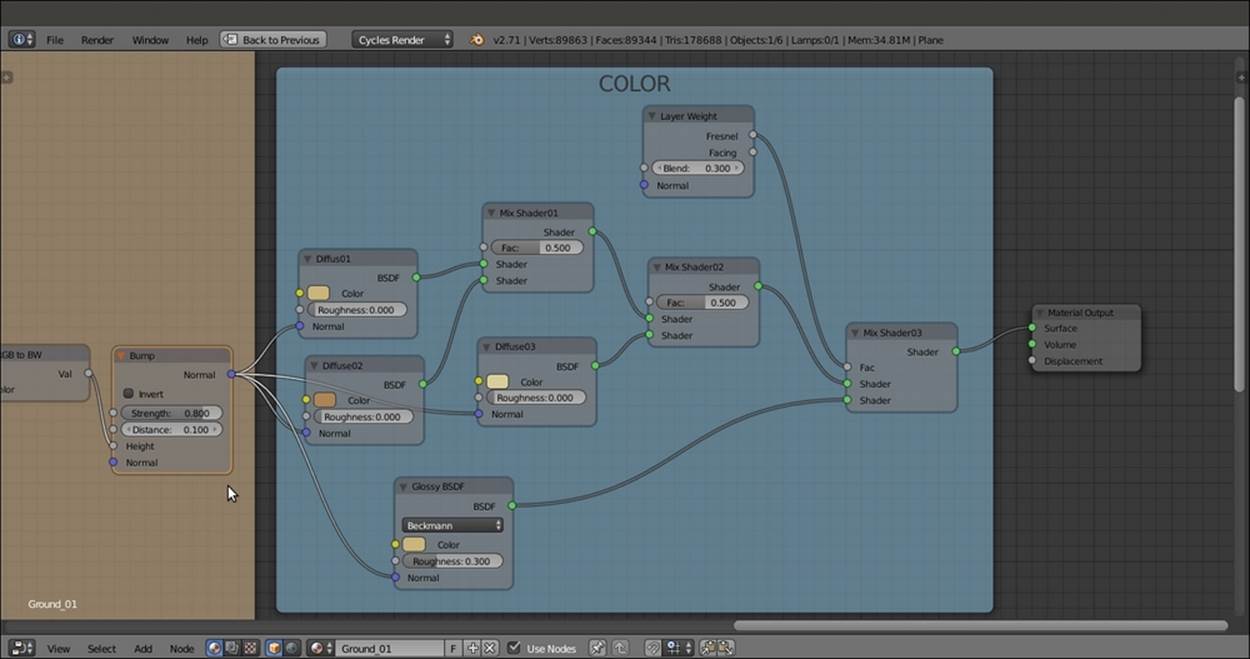
The COLOR frame
32. Add one more Noise Texture node (press Shift + A and navigate to Texture | Noise Texture) and a new ColorRamp node (press Shift + A and navigate to Converter | ColorRamp). Connect the Mapping node output to the Noise Texture node's Vectorinput (label it Noise Texture03) and the Fac output of Noise Texture to the Fac input of the ColorRamp node (label it ColorRamp03).
33. For the last time, add a MixRGB node and set the Blend Type to Difference. Then connect the Color output of the ColorRamp03 node to the Color1 input socket of the Difference node, and the Color output of the Difference node to the Fac input socket of the Mix Shader01 node. Set the Fac value of the Difference node to 0.255.
34. Set the Noise Texture03 node's scale to 1.000 and the Detail value to 5.000. Switch the ColorRamp03 node's Interpolation to B-Spline, move the 0 value of color stop to position 0.285, move the 1 color stop to position 0.740, and click on the + icon to add a new color stop. Set its color to black and move it to position 0.320.
35. Connect the output of the Dodge01 node inside the BUMP frame to the Color2 input socket of the Difference node. Connect the Color output of the ColorRamp02 node inside the BUMP frame to the Fac input socket of the Mix Shader02 node inside theCOLOR frame.
And we're done! Here is a screenshot of what the Blender UI will now look like:
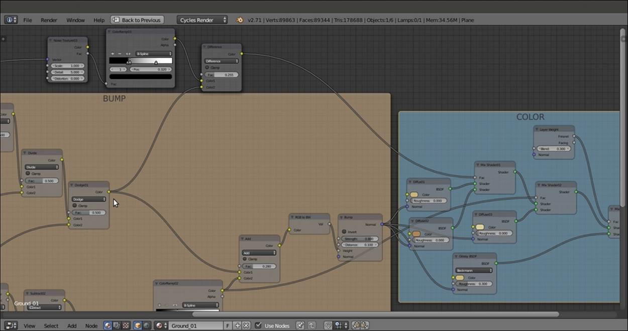
Part of the bump output is connected to the COLOR frame by the three upper nodes and the bottom ColorRamp node
How it works...
The way this material works is very similar to the sand material of the previous recipe, although a lot simpler:
· We mixed two slightly different colors using the values of a Noise Texture node as the stencil factor, then mixed a third, similar color on the ground of the bump output to obtain the whitish, pebble-like effect you see in the rendered image. We created the ground roughness using an ensemble of procedural textures mixed in several ways, whose total sum was then connected to the Normal input sockets of the three Diffuse BSDF nodes and of the Glossy BSDF shader, as shown in the following screenshot:
The overall vision of the ground material network
Creating a snow material using procedural textures
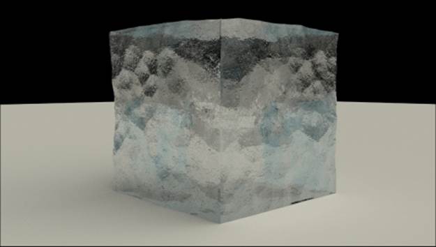
In this recipe, we will create a snow material, as shown in the following screenshot, and also fake a slight and cheap Subsurface Scattering effect:
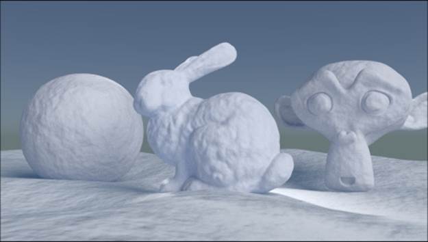
The snow material as it appears in the final rendering
Getting ready
Start Blender and open the 9931OS_Snow_start.blend file.
In this file, there is a prepared scene with a Spheroid (the usual Cube with a four-level Subdivision Surface modifier), a Suzanne (press Shift + A and navigate to Add | Mesh | Monkey) with a Subdivision Surface modifier as well, and the famous Stanford bunny (http://en.wikipedia.org/wiki/Stanford_bunny), leaning on a subdivided, displaced, and smoothed Plane renamed Snow_ground. Suzanne is Blender's mascot and an alternative to free test models such as the Stanford bunny itself. By the way, I thought of grouping them in the same scene to have different shapes to test the material.
In the file, there is also a Plane working as mesh-light and a Spot pointing in the opposite direction to try to enhance the translucency of the snow.
How to do it...
Let's start creating the snow material:
1. Go to the World window and click on the New button. Then click on the little square with a dot on the right side of the Color slot. From the menu, select Sky Texture.
2. Go to the Material window and select the Snow_ground item in the Outliner. Click on the New button in the Material window under the Properties panel or in the Node Editor toolbar. Rename the material as Snow_01.
3. Press Shift and select the Spheroid, Suzanne, and the Stanford bunny. Then select the Plane to have it as the active object. Press Ctrl + L and go to Materials.
4. Put the mouse cursor in the Camera view and press Shift + Z to set the Viewport Shading mode to Rendered.
5. In the Material window under the Properties panel to the right, under the Surface subpanel, switch the Diffuse BSDF shader with a Mix Shader node. In the first Shader slot, select a Diffuse BSDF shader, and in the second slot, select a Glossy BSDFshader.
6. Set the Roughness value of the Glossy BSDF shader to 0.300.
7. Add a Fresnel node (press Shift + A and navigate to Input | Fresnel) and a Math node (press Shift + A and navigate to Converter | Math). Set the IOR (short for Index Of Refraction) value of the Fresnel node to 1.300. Then connect its Fac output to the firstValue socket of the Math node. Set the second Value to 10.000 and the operation mode to Divide. Finally, connect its Value output to the Fac input socket of the Mix Shader node.
8. Add a Translucent BSDF node (press Shift + A and navigate to Shader | Translucent BSDF). Set its color values to 0.598 for R, 0.721 for G, and 1.000 for B.
9. Select the Mix Shader node, press Shift + D to duplicate it, and paste it between the first Mix Shader node and the Material Output node. Connect the Translucent BSDF node's output to the second input socket. Set the Fac value of the second Mix Shadernode to 0.300. Here is a screenshot of the basic shader for your reference:
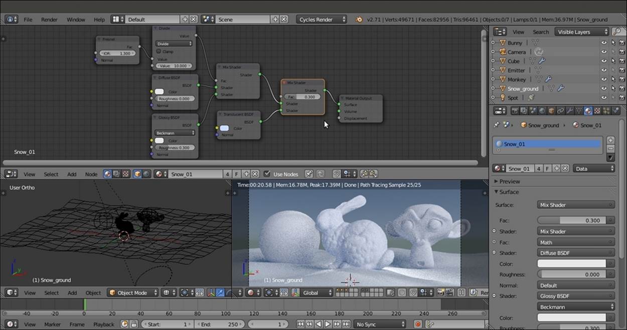
The basic shader for the snow material
10. Add a Noise Texture node (press Shift + A and navigate to Texture | Noise Texture) and press Shift + D to duplicate it. In the Properties panel of the Node Editor window (press the N key to make this appear if necessary), label them Noise Texture01 andNoise Texture02.
11. Add a Texture Coordinate node (press Shift + A and navigate to Input | Texture Coordinate) and a Mapping node (press Shift + A and navigate to Vector | Mapping). Connect the Object output of the Texture Coordinate node to the Vector input of theMapping node. Then connect the Vector output of the Mapping node to both the Vector input sockets of the Noise Texture nodes.
12. Add a Math node (press Shift + A and navigate to Converter | Math) and press Shift + D to duplicate it three times so that you obtain four Math nodes. Label them Math01, Math02, Math03, and Math04.
13. Connect the Noise Texture01 node's Fac output (the gray one) to the first Value input of the Math01 node and set the second Value to 2.000. Set the Operation to Multiply.
14. Connect the Fac output of the Noise Texture02 node to the first Value input of the Math02 node and let its second Value be the default, which is 0.500. Set the Operation to Multiply.
15. Now connect both the output of the two previous Math nodes to the input Value sockets of the Math03 node. Set the Operation to Add.
16. Connect the output of the Math03 node to the first Value input of the Math04 node. Set its Operation to Multiply and let the second Value be the default, which is 0.500.
17. Connect the Math04 node output to the Displacement input socket of the Material Output node.
18. Now go to the Noise Texture02 node and change the Scale value to 15.000. Leave the other values (also for the Noise Texture01 node) as they are (that is, 5.000 for Scale, 2.000 for Detail, and 0.000 for Distortion).
19. Go to the Mapping node and set the Scale value to 0.500 for all three axes. Now the Blender UI will look like what is shown in this screenshot:
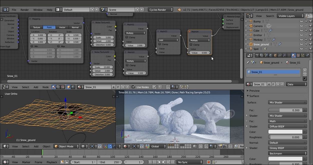
The bump pattern
20. Add two Frames, label them SNOW COLOR and SNOW BUMP, and parent the appropriate nodes to them as shown in the following screenshot:
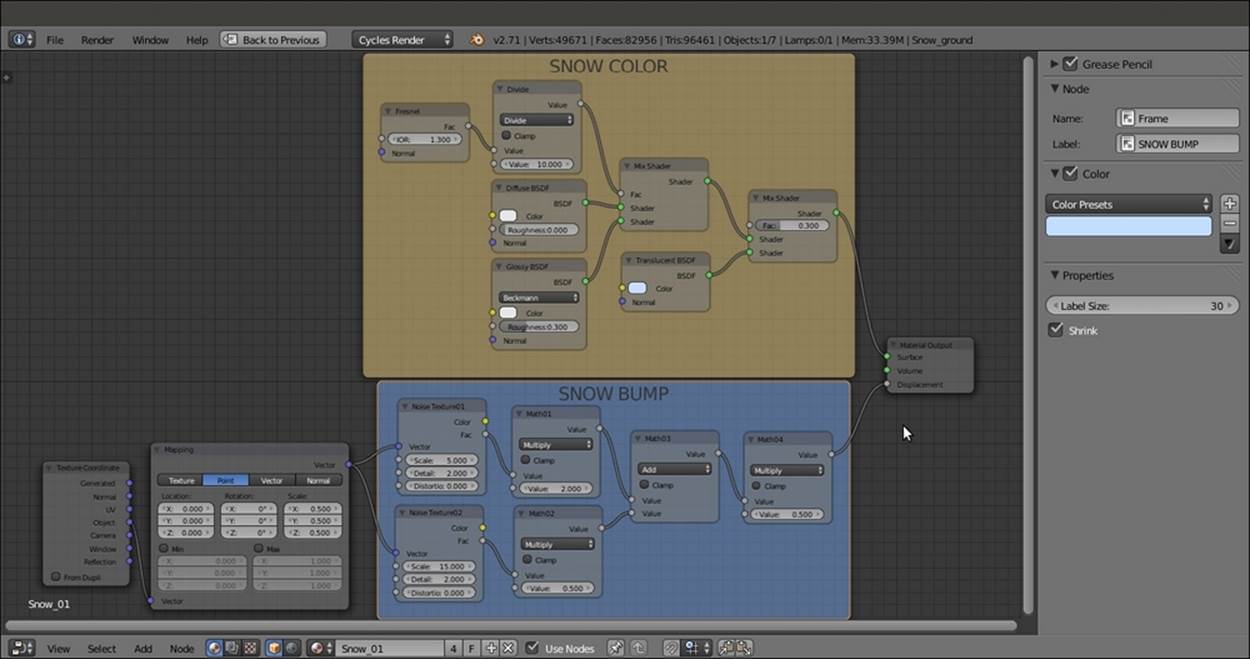
The overall vision of the snow material network
How it works...
As usual, to understand the creation of this material more easily, we will divide it into two stages: the first stage for the general color and consistency of the snow, and the second stage to add bumpiness to the surface. These stages are explained in detail as follows:
· First stage: We just made a basic shader by mixing the Diffuse BSDF and the Glossy BSDF shaders by the IOR value of the Fresnel node. The Fresnel output value is divided by the Math-Divide node to obtain a softer transition (try to change the second value from 10.000 to 1.000 to see a totally different effect). Then we also mixed a bluish Translucent shader but gave predominance to the basic shader by setting the factor value in the second Mix Shader node to 0.300. The Translucent shader gives the appearance of light seeping through snow and showing in the shadowed areas of the object, working as a very fast and cheap Subsurface Scattering effect.
· Second stage: We added two Noise Texture nodes with different scale values to simulate the bumpiness of soft snow. The first two Multiply-Math nodes set the influence of each noise separately. These values were merged by the Add-Math node and piped in one more Math node, set to Multiply as well, to establish the overall weight of the bump effect that, being directly connected to the Displacement input in the Material Output node, affects all the shaders in the network.
Creating an ice material using procedural textures
In this recipe, we will create a semi-transparent ice material that will look like this:
The ice material as it appears in the final rendering
Getting ready
Start Blender, load the 9931OS_start.blend file, and perform the following steps:
1. Delete the UV/Image Editor window by joining it with the 3D view.
2. Select the Plane item, go to Edit Mode, and scale it eight times bigger (press Tab, then press S, enter the digit 8, and press Enter). Go out of Edit Mode and move the Plane 1 unit upward (press Tab, then press G, enter the digit 1, press Z, and finally, pressEnter).
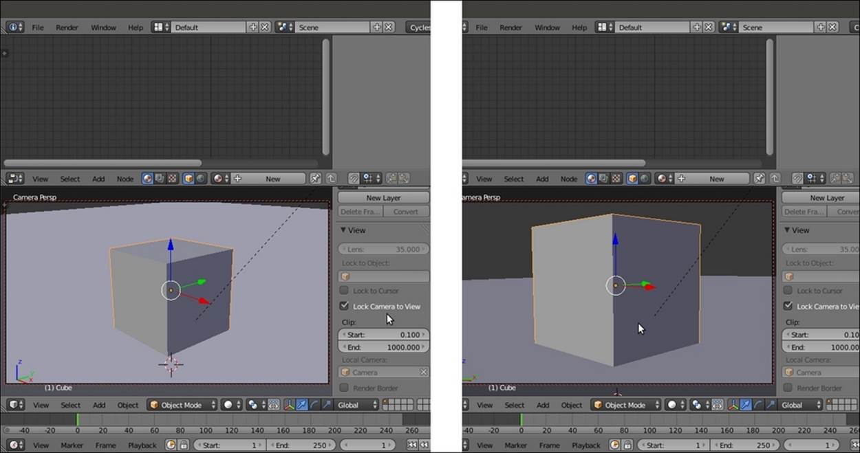
3. Select the Cube and press N to make the Properties panel visible. Go to the View subpanel and check the Lock Camera to View item. The borders of the Camera view turn red, which mean that you can directly use the mouse to move, zoom in, and adjust the position of the Camera around the selected object (the Cube in this case) to obtain a view similar what is shown in the right half of this screenshot:
4. Next, uncheck the Lock Camera to View item.
5. Go to the World window and set Color to black.
6. Select Sun Lamp in the Outliner, and in the Object data window, set the Strength value to 3.000, Size to 1.000, and the Color values to 0.900 for R, 0.872 for G, and 0.737 for B.
7. Select the Cube, go to Edit Mode, and press the W key. In the Specials pop-up menu, select Subdivide. Press the F6 key, and in the Subdivide pop-up panel under the 3D Cursor position, set Number of Cuts to 2. Go out of Edit Mode.
8. Go to the Object modifier window and assign a Subdivision Surface modifier to the Cube. Switch from Catmull-Clark to Simple. Set the Subdivisions levels to 5 for both View and Render. Check the Optimal Display item.
9. Assign a Displace modifier, and in the Textures window, click on New and select the Voronoi texture. Set the Size value to 1.20. Back in the Object modifiers window, set the displacement Strength to 0.050.
10. Assign a new Displace modifier and select Voronoi texture again, but this time, set the Size value to 0.80. Set the displacement Strength value to 0.075.
11. Assign a third Displace modifier, select the Voronoi texture, and leave the default size (0.25) as it is. Set the displacement Strength value to 0.020. Here is a screenshot of the displaced Cube primitive for your reference:
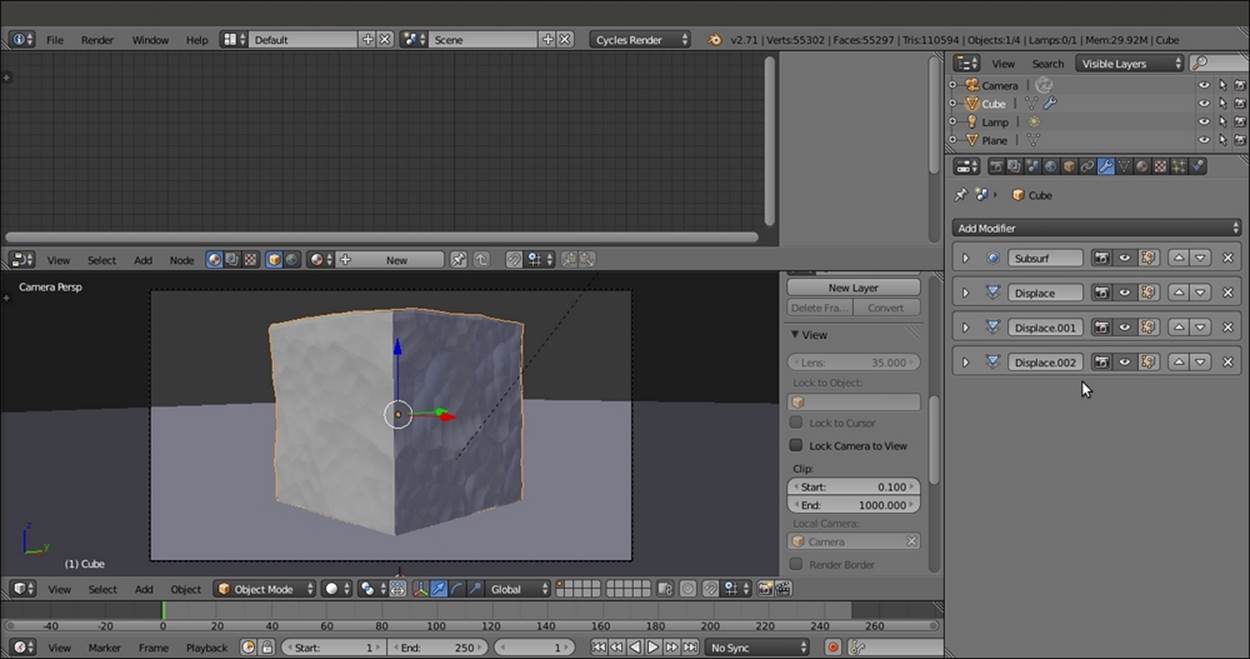
A screenshot in the Solid viewport shading mode of the displaced Cube primitive
12. Switch the Camera's Viewport Shading to the Rendered mode.
How to do it...
After preparing the scene, we are going to create the material:
1. Select the Cube and click on New in the Material window under the Properties panel or in the Node Editor toolbar. Rename the material Ice_01.
2. In the Material window to the right of the screen, under the Surface subpanel, switch the Diffuse BSDF shader with a Mix Shader node. In the first Shader slot, select a Glass BSDF shader, and in the second slot, select a Transparent BSDF shader.
3. Set the Glass BSDF shader's color totally white and the IOR value to 1.309. Set the Transparent BSDF shader's color values to 0.448 for R, 0.813 for G, and 1.000 for B.
4. Add a Fresnel node (press Shift + A and navigate to Input | Fresnel) and connect it to the Fac input socket of the Mix Shader node. Then set the IOR value to 1.309.
5. Add a Glossy BSDF shader (press Shift + A and navigate to Shader | Glossy BSDF). Set the color to pure white and the Roughness value to 0.050.
6. Select the Mix Shader node and press Shift + D to duplicate it. Connect the output of the first Mix Shader node to the first Shader input socket of the duplicated one, and the Glossy BSDF shader output to the second Shader input socket. Add a Layer Weightnode (press Shift + A and navigate to Input | Layer Weight) and connect the Facing output to the Fac socket of the second Mix Shader node.
7. Add a Voronoi Texture node (press Shift + A and navigate to Texture | Voronoi Texture). Set Coloring to Cells and the Scale value to 25.000.
8. Add a Noise Texture node (press Shift + A and navigate to Texture | Noise Texture) and set only the Scale value to 25.000.
9. Add a Math node (press Shift + A and navigate to Converter | Math) and set Operation to Maximum. Connect the Fac output of the Voronoi Texture and Noise Texture nodes to the first and the second Value input of the Math node.
10. Add a Bump node (press Shift + A and navigate to Vector | Bump). Connect the Maximum-Math node output to the Height input of the Bump node, and its Normal output to the Normal input sockets of the Glass BSDF and Glossy BSDF shaders.
11. Set the Strength value of the Bump node to 0.250.
12. Add an RGB Curves node (press Shift + A and navigate to Color | RGB Curves) and paste it between the Maximum-Math and the Bump nodes. Set the point in the little window of the node interface at these coordinates: 0.25455 for X and 0.28125 for Y. Click on the little window to create a new point and set its coordinates to 0.74091 for X and 0.26250 for Y.
13. Add a Texture Coordinate node (press Shift + A and navigate to Input| Texture Coordinate) and a Mapping node (press Shift + A and navigate to Vector | Mapping). Connect the Object output of the Texture Coordinate node to the Vector input of theMapping node. Then connect the Vector output of the Mapping node to the Vector input sockets of both the Voronoi Texture and Noise Texture nodes, as shown in the following screenshot:
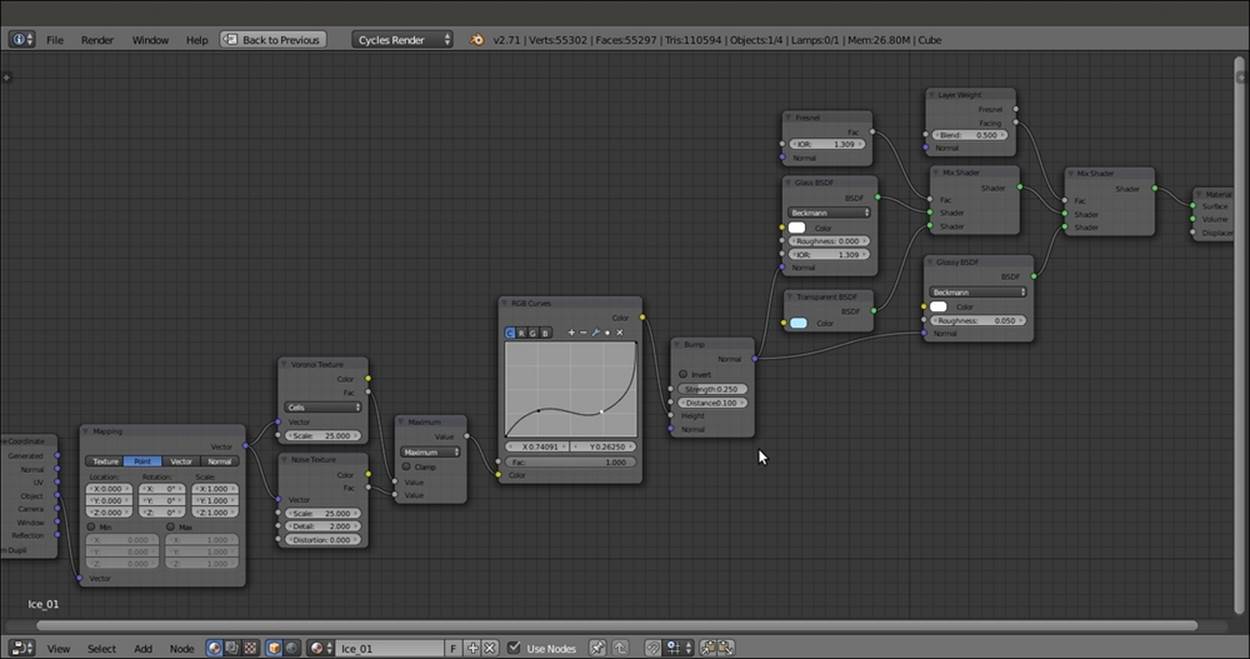
The quite simple network of nodes for the ice material
How it works...
This time, we started by mixing a Glass BSDF shader and a Transparent shader node, modulated by a Fresnel node, and we set the IOR values of both the Fresnel and the Glass BSDF to the refraction value of ice. We also added a Glossy BSDF shader to provide specularity, mixed by a Layer Weight node set on Facing (because the more a mesh normal faces the point of view, the more evident the specular effect is).
Then, using mixed procedural textures, we created the bump effect to perturb the surface of the object (note that the bump also affects the material's refraction).
See also
Here are some links to lists of IOR values that can be used in mixing the Diffuse BSDF component with the Glossy BSDF component through a Fresnel node:
· http://blenderartists.org/forum/showthread.php?71202-Material-IOR-Value-reference
· http://blenderartists.org/forum/showthread.php?117271-The-IOR-of-diferent-materials
The following is a computational and scientific search engine that allows you to quickly research the IOR of a given substance by typing its name:
· http://www.wolframalpha.com/
All materials on the site are licensed Creative Commons Attribution-Sharealike 3.0 Unported CC BY-SA 3.0 & GNU Free Documentation License (GFDL)
If you are the copyright holder of any material contained on our site and intend to remove it, please contact our site administrator for approval.
© 2016-2026 All site design rights belong to S.Y.A.