Emerging Trends in Image Processing, Computer Vision, and Pattern Recognition, 1st Edition (2015)
Part III. Registration, Matching, and Pattern Recognition
Chapter 38. Detection and matching of object using proposed signature
Hany A. Elsalamony Mathematics Department, Faculty of Science, Helwan University, Cairo, Egypt
Abstract
Most of algorithms of object detection and classifications are only locating regions in the image, whether it is within a template-sliding mask or interested region blobs. However, such regions may be ambiguous, especially when the object of interest is very small, unclear, or anything else. This chapter presents proposed algorithm for automatic object detection and matching based on its own proposed signature using morphological segmentation tools. Moreover, the algorithm tries to match the objects; neither among object's blobs nor among regions of interest; but among the constructed proposed objects' signatures. In the matching process, speeded up to robust features (SURF) method has been presented to make a comparison on the experimental results. The performance has been tested 120 from a wide variety of unlike objects; it has been achieved 100% in the case of constructing object signatures, also it has been achieved 96% of right matching whereas SURF has achieved 85% for all test objects.
Keywords
Object detection and matching
Signature
SURF
Segmentation
1 Introduction
The object detection plays an important role in the area of computer vision research. Nowadays, many of its applications require the locations of objects in images. In fact, there are two closely related definitions, object presence detection, and object localization. The determinations of one or more of an object class are presented (at any location or scale) in an image, which means of an object's presence detection or image classification, and can be suitable for image retrieval based on an object [1]. While the object localization means finding the object location and scale an image.
Many of the object detection algorithms are following the model of detection by parts, which was introduced by Fischler and Elschlager [2]. They used the object structural modeling and reliable part detectors' methods. The basic idea behind this model is to identify that the individual parts of an object detector are easier to build than that for the full object [3,4]. Actually, these methods of object detection are depending on sliding a window or template mask through the image to classify each object falls in the local windows of background or target [5,6]. In fact, this approach has successfully used to detect rigid objects such as cars and faces, and has even applied to articulated objects such as pedestrians [7–9].
Later, a frequency model is proposed, which is dependent on a moving background containing repetitive structures. The authors considered special temporal neighborhoods of the pixels, which they have applied local Fourier transforms in the scene [10]. The feature vectors are generated to build a background model. However, they are applied their model for moving object and backgrounds, on both synthetic and real image sequences [11].
On the other hand, another popular approach is depending on extracting the local interest points through the image and then classifies the regions, which contained these points, instead of looking at all possible sub-windows, as in the previous [12]. The greatest common divisor of the above approaches is that they can fail when the regional image information is insufficient (target is very small or unclear), and this is considered as a weakness of them [13].
In this way, the image matching based on features is depending on analyzing the extracted features and find the corresponding relationship between them [12]. The image matching is not accurate enough because the images are often noisy, in different illuminations and scales. Recently, extracted features are widely applied in the field of object matching. In 1999, the scale invariant feature transforms (SIFT) presented by Lowe, when a robust descriptor and difference-of-Gaussians detector was used [14,15]. It is interesting to note that the advantages of SIFT; that it is applied on invariant rotation or image scale, is about its computation, which is very hard to calculate and take a time because it needs to extract 128 dimensional descriptors to work [16]. This problem was solved in 2008 by Bay, who proposed speeded up to robust features (SURF); 64 dimensions modeled it. The experiments of SURF have assumed the integrated images to compute a rough approximation of the Hessian matrix, and this is tended faster than SIFT [17,18]. In 2009, Lue and Oubong compared SIFT and SURF; they have pointed out that SURF is better in performance but is not efficient in rotational changes [19]. In fact, the effective power of SURF has been reduced because the ignoring of features in geometric relationships [19,20].
This chapter presents proposed algorithm depending on the object geometrical shape, and relationship between outer points of the objects' contours. It is divided into two parts; one is constructing an own signature for any object in an image and the other is matching operation among all object shapes' signatures to get exactly which they are described. In addition, four steps have to process through these parts. Firstly, constructing signatures for all objects in an image and saving them as data in the system. Secondly, constructing signatures for all test input objects. The comparisons between inputs and saved signatures, which they have determined before, have operated using statistical methods in the third step. Finally, these signatures have used to detect and define the objects in the image.
In fact, the proposed approach introduces an idea to detect an object dependent on its outer shape by constructing an own signature, which let the object to be free from constraints such as rotation, size, and its position in the image. This proposed idea will may use in many fields like identifying the kinds of plants, fruits, and any other objects based on their shapes. The succeeding section is discussing SURF method because it is the most important one in the object detection and matching ways.
The rest of this chapter is organized as follows. Section 2 introduces an overview on SURF. A brief overview on image segmentation is discussed in Section 3. In Section 4, the proposed algorithm of detection and matching has been illustrated. The algorithm's experimental results are detailed in Section 5 and the conclusion in Section 6.
2 Overview on SURF method
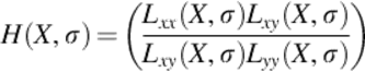
The initial mention of SURF was by Bay in 2006. It has four major stages: Hessian matrix, localization of these points, orientation assignment, and descriptor, which is depended on Haar wavelet response's sum [18]. In the first, Hessian matrix is based on detection in scale space of interested points. Additionally, the determinant of Hessian matrix has used as a preference to look for local maximum value, and the detection of SURF interested point is based on theory of scale space. Equation (1) illustrates in details the components of Hessian matrix. In this equation, there is a point X = (x, y) in an image I, the Hessian matrix H(X, σ) in X at scale σ has defined as follows:
 (1)
(1)
where Lxx(X, σ) represents the convolution of the Gaussian second-order partial derivative. δ2g(σ)/δx2 with the image I in a point X, and similarly for Lxy(X, σ) with δ2g(σ)/δxδy and Lyy(X, σ) by δ2g(σ)/δy2.
To speed up the convolution, 9 × 9 box filter is utilized to approximate integral image and the second-order Gaussian partial derivatives with σ = 1.2 [18]. The symbols Dxx, Dxy, and Dyy, are denoting the convolution results’ approximations. The determinant of Hessian matrix is
![]() (2)
(2)
where w is recommended as 0.9, that is the relative weight of the filter responses [17,18]. The step after is dividing the image into many regions, each one contains different scale image templates.
The second stage is the interested point localization. First step in this stage is setting a threshold to the detected Hessian matrix of extreme points. Second step, to obtain these points a nonmaximum suppression in a 3 × 3 × 3 neighborhoods have applied. The bases of selecting a feature point are that only the point with value bigger than the neighboring 26 points' value has chosen as a feature point [18].
The third stage is the orientation assignment, that is starting by calculating the Haar wavelet (Haar side: 4s, where s is the scale at which the interest point was detected) responses in the x and y direction within a circular neighborhood of radius 6s around the interest point. The responses have centered at the interested point and weighted with Gaussian (2s). At that moment, the sum has calculated for all responses within sliding orientation window of size π/3 to estimate the leading orientation, then determining the sum of horizontal and vertical responses within the window. A local orientation vector has produced with the two collected responses, such that the longest vector over all windows defines the orientation of the interest point.
Last stage in SURF is the descriptor based on sum of Haar wavelet responses. For the extraction of the descriptor, the first step consists of constructing a square template region (the size is 20s) oriented along the selected orientation and centered on the interested point. The region splits up regularly into smaller 4 × 4 square subregions. For each subregion, Haar wavelet responses have computed at 5 × 5 regularly spaced sample points. Simply, the Haar wavelet response in horizontal direction is denoted by dx, also the Haar wavelet response in vertical direction by dy. The responses dxand dy are first weighted with a Gaussian (σ = 3.3s) centered at the interested point. Moreover, the responses |dx| and |dy| are extracted to bring in information about the polarity of changes in the intensity. Hence, the structure of each subregion has four-dimensional descriptor vector Vsub:
![]() (3)
(3)
From the previous, by multiplying all 4 × 4 subregions results in a descriptor vector of length are 4 × (4 × 4) = 64 [17,18]. Additionally, to judge whether the two feature points of images are matched or not, the distance of the characteristic vector between two feature points is calculated. Finally, it is interesting to note that SURF ignores the geometric relationship between the features, which is very important characteristic of many objects in the image. For that reason, this chapter presents proposed algorithm to detect and matching objects based on own constructed signatures.
3 Overview on Image Segmentation
The segmentation idea is splitting an image into many various regions containing every pixel with similar characteristics such that; texture information, motion, color, whereas the detection stage has to choose relevant regions and assign objects for further processing [3,21]. In addition, these regions should strongly related to the detected objects or features of interest to be meaningful and useful for image analysis and interpretation. Actually, the transformation from gray scale or color image in a low-level image into one or more other images in a high-level image, which is depending on features, objects, and scenes, represents the first step in significant segmentation. Generally, the accurate partitioning of an image is the main challenging problem in image analysis, and the success of it depends on consistency of segmentation [12].
On the other hand, segmentation techniques are divided into either contextual or noncontextual. The noncontextual techniques do not care about account of special relations between features in an image and group pixels together based on some global attribute, for example, gray level or color. However, contextual techniques mainly are exploiting these relations, for example, pixels with similar gray levels, and close spatial locations grouped with each other [1,3]. Actually, the proposed algorithm is trying to exploit the segmentation contextual techniques in object detection and classification. Succeeding section illustrates in details the idea for the suggested algorithm.
4 The proposed algorithm
The proposed object detection and matching framework are divided into three parts. They are consisting of segmentation, construction of objects' signatures in image, and matching them to classify the object based on its signature [13]. The segmentation process represents the main stone in this algorithm, which is giving initial hypotheses of object positions, scales and supporting based on matching. These hypotheses are then refined through the object signature classifier, to obtain final detection and signatures matching results. Figure 1 describes all steps of the proposed algorithm [22].
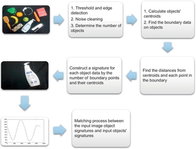
FIGURE 1 The proposed algorithm steps.
This figure starts by an example of original RGB image with all different objects, many morphological functions and filters (edge detection, erosion, dilation, determination the number of objects, watershed segmentation, etc.) are applied to enhance the work of this image. The areas, centroids, orientations, eccentricities, convex areas for every object can easily be determined. Moreover, the boundary points (xij, yij) for each object are calculated individually, where i represents the number of objects and j is the number of boundary points related to an object. These boundary points and the objects' previous information are saved to start construction of own proposed signature for every object based on all these information. The relation among all these information and Euclidian distance from objects' centroids (xtc,ytc) is plotted and saved as an individual signature for each object, that is shown in Figure 1 by one object. These signatures for all objects are saved and waiting for matching with any input object's signature, as in Section 5. Moreover, the contour is drawn around all objects and tracing the exterior boundaries of them.
The third part of this proposed algorithm after segmentation and constructing signatures is the matching process between input and saved objects' signatures as in the above. Two different ways in matching process have used to make a comparison between them in accuracy and activity; one is using statistical measures related to the signatures and the second is using SURF [22].
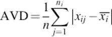
Additionally, all shown steps in Figure 1 have applied on the input object to construct its signature. Actually, the matching process is depending on statistical measures on both types of objects' signatures (saved ones and input). Firstly, as shown in Figure 1, not all objects in the example image are in the same size, orientation, or even shape, and afterwards, their data should not be equal in length or characteristics. For that reason and more in checking accuracy, some preprocesses of matching have carried out; one is sorting all the data of all signatures, and then computing the variability in the dataset by calculating the average of the absolute deviations of data points from their mean. The equation for average deviation is
 (4)
(4)
For all i's are the number of objects in the image and j's are the number of object's signature data, xij represents the number of signature's data points, ![]() is their mean, and ni is the number of signature data rows. Secondly, the results of Equation (4) have applied on all input and saved objects to make a comparison between them for get the exact matching by least error. Equation (5) introduces a method for calculate differences between the results of Equation (4):
is their mean, and ni is the number of signature data rows. Secondly, the results of Equation (4) have applied on all input and saved objects to make a comparison between them for get the exact matching by least error. Equation (5) introduces a method for calculate differences between the results of Equation (4):
![]() (5)
(5)
The components of Equation (5) are the absolute value of the difference between the two results of Equation (4) related to saved and input object signatures. The decision of matching based on the least value of DIF, which is given the exact matched object.
5 Experimental results
The experimental results are divided into two parts; one is representing the objects and their signatures in images and the second is showing the results of matching and comparing a proposed algorithm with SURF methods.
Figure 2 presents a sample of experimentally clear and unclear images, which contain some standard geometrical shapes in (a), some kinds of objects varying in shapes, and luminance intensity in (b)–(f). Sequentially, the signatures have been constructed for the most distinct mentioned objects.
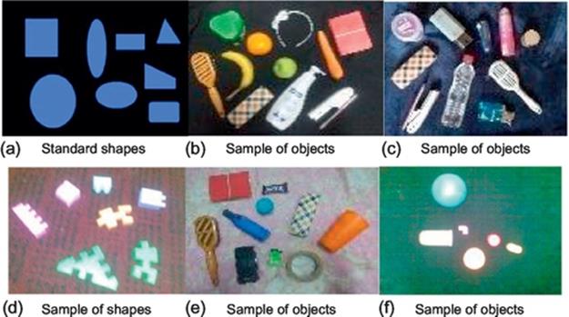
FIGURE 2 Images of famous regular shapes in (a) and from (b) to (f) other types of different objects.
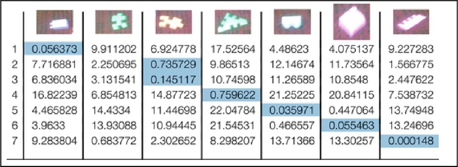
In Figure 3, all objects are individually be defined, detected, and matched by its signatures in the proposed algorithm.
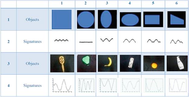
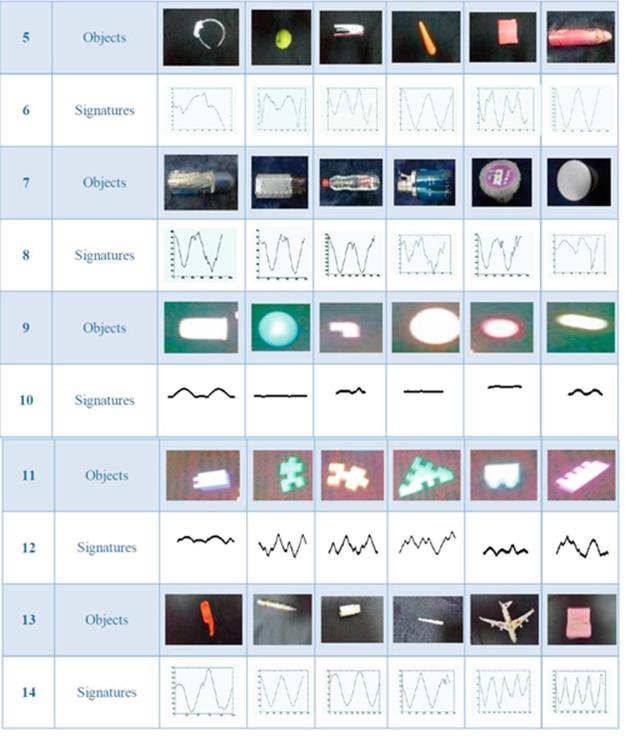
FIGURE 3 Different objects and their signatures.
It is interesting to note that the similarity is cleared in signatures for the stand ellipse (its major axis parallel to the y-axis) and horizontal one (its major axis parallel to the x-axis) because it is the same shape but different position. Evidently, the square shape has four identical peaks in its signature because the equality of its sides; furthermore, the circle's signature is one-line parallel to the x-axis and far away its radius length. On the same way, many objects' signatures are nearest to each others, for example, the object (1, 2) (i.e., in the row 1 and column 2 in Figure 3) is closer in signatures with objects in cells (9, 2), (9, 4). In the same context, signatures of objects (1, 3) and (5, 4) are seemed to correspond to some. These last cases are happened because the shape's nature of the original objects not because mistakes or big errors in the proposed algorithm.
Actually, the proposed algorithm has applied on about 120 different shapes, positions, orientations, and intensity luminance of objects in RGB images. Furthermore, signature's determination for all objects has achieved 100% without any errors (in data, or wrong signature construction) for all objects.
Second part of the proposed algorithm is matching of input and saved signatures. Table 1 presents the matching process that is depending on Equations (4) and (5); the decision in this process is based on the least value in Equation (5). Obviously, Table 1 shows all input objects images in first row. Regularly, the first column represents all positions (1-11) of objects in their main image if are scanned from left to right. Sequentially, Table 1 consists of x rows and y columns, which contain a set of values, represent the smallest value of errors calculated by Equation (5). For example, in the cell (1, 1), the proposed algorithm is selected a least value (0.1097) in a row (1), which indicates to the first object in the image. Clearly, this value indicates to the exact object position selected in the main image of Figure 2(b). In this case, the input object has been completely different in its position and orientation; however, the proposed matching algorithm is overcome that and succeeded. In fact, all other objects have been matched by the same way and have achieved 100% for that image.
Table 1
The Matching Process of Objects' Signatures
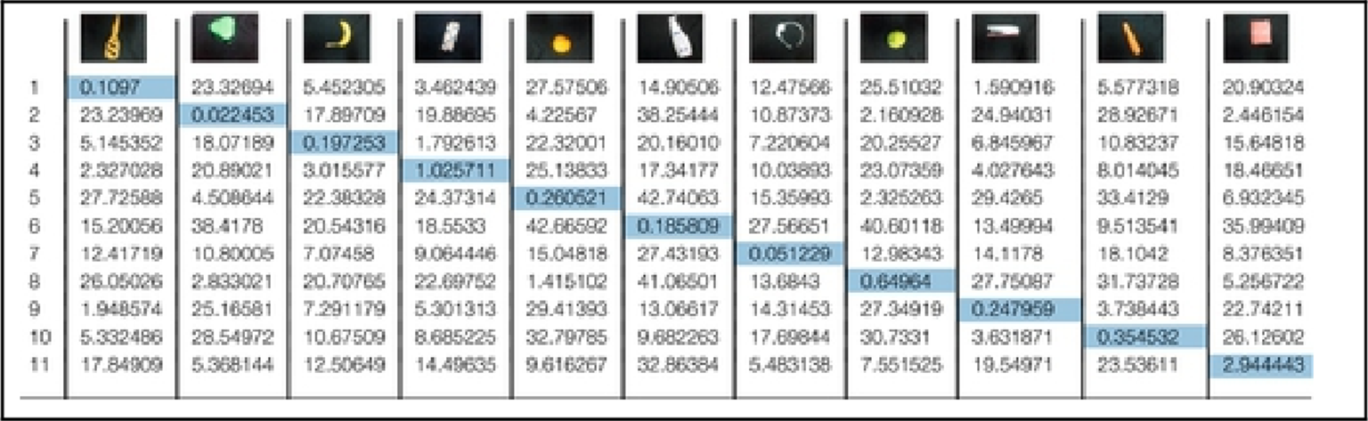
Table 2 presents error values for another image in the matching process based on objects' signatures, which are applied on unclear image in Figure 2(d). As in Table 1, all cell's values represent the DIF of Equation (5), and the least value indicates to exact match of objects in an image and the input one. Clearly, as seen one mismatching is found in second row column two; however, this mismatching is acceptable because the objects in second and third columns are so close to each other in shape.
Table 2
The Matching Process of Objects' Signatures
As the same way in Tables 1 and 2, all other objects have been selected based on their signatures and have achieved 96% in the matching process. On the other hand, by applying SURF on the same image with different input objects, some mismatching is found if the input object has changed in his position or orientation; even so, this mismatching has not happened with the proposed algorithm under the same constraints. Figure 4 illustrates SURF Work in an example for this mismatching with the second object in second column of Table 1 by 100 strongest feature points.
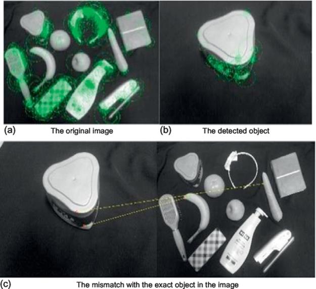
FIGURE 4 The SURF example with the mismatch an object. (a) The original image; (b) the detected object; (c) the mismatch with the exact object in the image.
In this figure, the input object in the left is mismatched with its corresponding object in the original image. Additionally, this mismatch repeats many times with the test objects using SURF. From the previous results, although SURF method and proposed algorithm have presented to detect and matching objects in an image; however, the presented algorithm is more effective and accurate in objects matching process than SURF and simply in use by some humble statistical equations without any constraints as in the other methods. Next section shows the conclusion of this work.
In Figure 5, another example for mismatching of objects using SURF method whereas exact matching has illustrated in Figure 6.
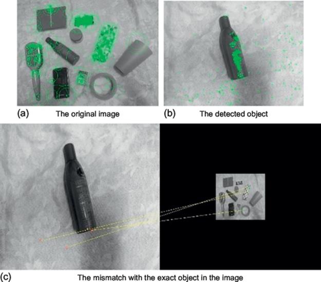
FIGURE 5 The SURF example with the mismatch an object. (a) The original image; (b) the detected object; (c) the exact matching with the exact object in the image.
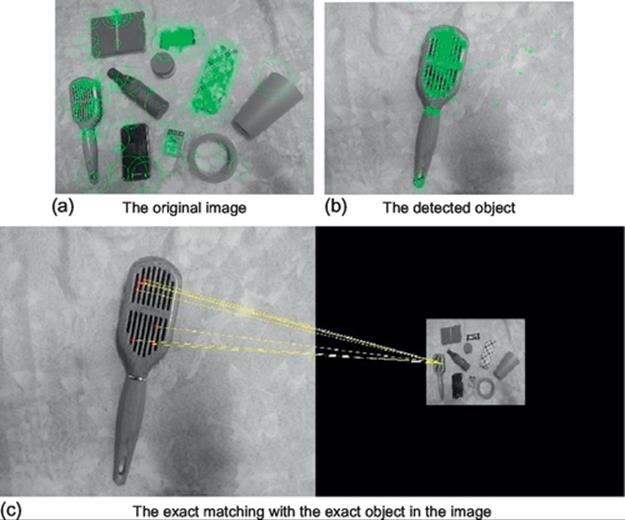
FIGURE 6 The SURF example with the exact match an object. (a) The original image; (b) the detected object; (c) the exact matching with the exact object in the image.
6 Conclusions
This chapter has presented proposed algorithm for object detection and matching based on its own signature using morphological segmentation tools. The algorithm has divided into three parts; first is segmentation process, second is the construction of object signatures, and the last part is the matching based on them to classify and define the object. Actually, this signature has a singularity, simply in use, saving it on a small memory, and working in a variety of light levels. Moreover, the proposed algorithm matched the objects neither among object's blobs nor regions of interest; but among the constructed signatures. On the other hand, SURF method has been presented for comparison with the proposed method on the experimental results. Many difficulties are appeared in matching process, such as object in unusual intensity luminance, shape, orientation, position, different sizes, or unclear image of objects; but the proposed algorithm has overcome on them, while SURF has not done. The performance has been tested 120 from a wide variety of different objects; it has been achieved 100% in the case of constructing object signatures, also it has achieved 96% of exact matching whereas SURF has achieved 85% for all experimental objects.
References
[1] Elsalamony HA. Automatic video stream indexing and retrieving based on face detection using wavelet transformation. In: Second international conference on signal processing systems (ICSPS) 5-7 July, 2010; 2010:153–157.
[2] Fischler M, Elschlager R. The representation and matching of pictorial structures. IEEE Trans Comput. 1973;C-22(1):67–92.
[3] Bouchard G, Triggs B. A hierarchical part-based model for visual object categorization. In: IEEE computer society conference on computer vision and pattern recognition; 2005.
[4] He L, Wang H, Zhang H. Object detection by parts using appearance, structural and shape features. In: International conference on mechatronics and automation (ICMA); 2011:489–494.
[5] Huttenlocher D, Lilien R, Olson C. View-based recognition using an eigenspace approximation to the Hausdorff measure. IEEE Trans Pattern Anal Mach Intell. 1999;21(9):951–955.
[6] Lai K, Bo L, Ren X, Fox D. Detection-based object labeling in 3D scenes. In: International conference on robotics and automation, 2012; 2012.
[7] Gavrila D, Philomin V. Real-time object detection for smart vehicles. In: Proceedings. 7th international conference on computer vision; 1999:87–93.
[8] Rowley HA, Baluja S, Kanade T. Human face detection in visual scenes. Adv Neur Inf. 1995;8.
[9] Viola P, Jones M, Snow D. Detecting pedestrians using patterns of motion and appearance. In: IEEE conference on computer vision and pattern recognition; 2003.
[10] Zahn C, Roskies R. Fourier descriptors for plane closed curves. IEEE Trans Comput. 1972;21(3):269–281.
[11] Ali I, Mille J, Tougne L. Space–time spectral model for object detection in dynamic textured background. Pattern Recogn Lett. 2012;33(13):1710–1716 ISSN 0167–8655.
[12] Veltkamp RC, Hagedoorn M. State of the art in shape matching. Technical Report UU-CS-1999-27, Utrecht; 1999.
[13] Elsalamony HA. Automatic object detection and matching based on proposed signature. 68–73. International conference on audio, language and image processing (ICALIP), 16-18 July, 2012. 2012;vol. 1.
[14] Lowe DG. Distinctive image features from scale-invariant key points. Int J Comput Vis. 2004;60:91–110.
[15] Lowe DG. Object recognition from local scale-invariant features. In: Proceedings of the international conference on computer vision, Greece, 1999; 1999.
[16] Ke Y, Sukthankar R. PCA-SIFT: a more distinctive representation for local image descriptors. In: Proceedings of the IEEE conference on computer vision and pattern recognition, USA, 2004; 2004.
[17] Bay H, Ess A, Tuytelaars T, VanGool L. Surf: speeded up robust features. Int J Comput Vis Image Und. 2008;110:404–417.
[18] Bay H, Tuytelaars T, VanGool L. Surf: speeded up robust features. In: Proceedings of the European conference on computer vision, Austria, 2006; 2006.
[19] Juan L, Gwun O. A comparison of SIFT, PCA-SIFT and SURF. Int J Image Process. 2009;3:143–152.
[20] Amit Y, Geman D, Wilder K. Joint induction of shape features and tree classifiers. IEEE Trans Pattern Anal Mach Intell. 1997;19(11):1300–1305.
[21] Darwish AA, Ali HF, El-Salamony HAM. 3D human body motion detection and tracking in video. In: The 14th IASTED international conference on applied simulation and modeling, Spain, June 15-17, 2005; 2005.
[22] Elsalamony HA. Object detection and matching using proposed signature and surf. In: Eightenth international conference. Image processing, computer vision, and pattern recognition. IPVC’14, Worldcomp’14 proceeding, Las Vigas, Nevada, USA, July 21-24, 2014; 2014:377–383.
All materials on the site are licensed Creative Commons Attribution-Sharealike 3.0 Unported CC BY-SA 3.0 & GNU Free Documentation License (GFDL)
If you are the copyright holder of any material contained on our site and intend to remove it, please contact our site administrator for approval.
© 2016-2026 All site design rights belong to S.Y.A.