Idiot's Guides: 3D Printing (2015)
PART 4
3D Modeling
CHAPTER 17
Practical Reverse Engineering
In This Chapter
![]()
· Why you’ll want to learn reverse engineering
· Measurement tools that are useful and affordable
· Techniques for determining part dimensions
· The two ways you can model a part
In the context of 3D printing, reverse engineering is the practice of duplicating the design of a part or assembly. It’s easy to see why this is a useful skill to learn for the 3D printing enthusiast. If you want to reproduce a part or interface with an existing part, you’ll need to know how to reverse engineer it.
Luckily, reverse engineering simple parts probably isn’t quite as difficult as you’re expecting. It’s a relatively simple process of taking measurements and 3D modeling the part based on that. However, actually taking accurate measurements can be a little tricky in some cases, so I’ve given you some helpful tips and hints in this chapter to help you out.
Why You Should Learn Basic Reverse Engineering
One use for 3D printing that many people are interested in is the ability to replace broken parts they come across. Broken shelf brackets, car parts, and really anything made of plastic can be replaced with a 3D-printed part. Spending 50¢ on filament is sure better than buying overpriced replacement parts from the manufacturer (if they’re even available).
In some cases, you may be able to find some of those parts online that someone else modeled. But most likely, the majority of the things you’ll want to replace haven’t been modeled yet. For that reason, you’ll need to learn how to do it yourself.
Reverse engineering a part may sound a bit overwhelming, but it’s not as bad as it sounds. All you’ll be doing is 3D modeling a part as closely to the original as possible. You’ll just be taking measurements and making sure the important measurements are as accurate as possible.
![]()
DEFINITION
Reverse engineering, in a general sense, is the process of determining the function and/or design of a man-made object or system. This can be anything from reverse engineering software to complicated mechanical systems.
So which measurements are the important ones? They’re the ones for things like screw and bolt holes, the overall shape and size of the part, and any functional features. For most things you’ll probably want to replace, there will probably only be a few features that have to be exact. This means there is almost always some room for inaccuracy on the unimportant features.
Finding the Right Measurement Tools
There are a wide range of tools used to measure parts for reverse engineering. Professional engineers use some expensive tools like comparators, go/no go gauges, or thread gauges. These are precision tools (with the gauges needing to be bought in sets) and are usually quite expensive. In a professional environment, they also need to be regularly checked to ensure that they are within spec. Luckily for hobbyists, though, most of those aren’t necessary for the kind of reverse engineering you’d be doing at home.
The following describe the two most commonly used measurement tools by hobbyists; as you’ll learn, one is a necessity for measuring, while the other is one you should probably stay away from.
Digital Calipers: A Necessary Tool
Calipers are a simple measurement tool that measure the distance between the arms of the slide. Even in the professional world, digital calipers are what engineers use most of the time. They’re a surprisingly versatile instrument. Digital calipers can be used to measure interior distances, exterior distances, and usually depths as well. With simple distance measurements, most other measurements (like angles and radii) can be deduced.
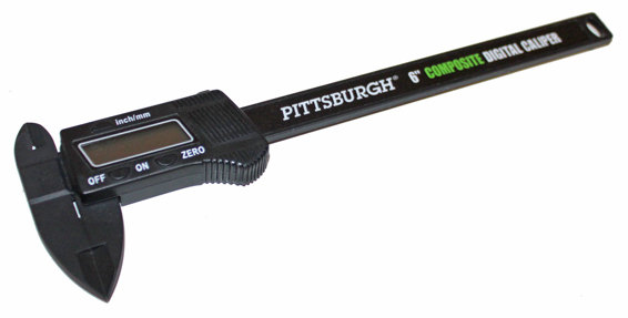
A very inexpensive pair of digital calipers.
These days, simple digital calipers can be purchased for less than $20. Even at that price, they’re still reasonably accurate. The accuracy of digital calipers is usually within 0.02mm, which is better than most 3D printers are capable of anyway.
![]()
HOT TIP
Don’t bother spending a lot of money on your first pair of digital calipers. High-end digital calipers can be pretty pricey and are unnecessary for hobby tasks. Inexpensive calipers will do just fine for most people outside of a professional engineering environment.
3D Scanners: Not All They’re Cracked Up to Be
If you’ve been investigating 3D printers, you may have also come across 3D scanners. 3D scanners are devices that optically measure thousands of points on the surface of an object. With those points measured, a computer can reconstruct the surface of a 3D object.
The idea is that you can just throw a part on the 3D scanner, scan it, and then print a perfect copy. The appeal of this is pretty obvious; it takes away all of the trouble of having to reverse engineer a part. But do 3D scanners fulfill their purpose?
The short answer, unfortunately, is no. This is for two big reasons: the accuracy of the scan and the usability of the resulting model. Both of these are a pretty big deal and are keeping 3D scanners from being particularly useful in engineering applications.
The accuracy issue is one which you can probably see the problem with pretty easily. Even high-quality scanners tend to result in imperfect models. That’s especially true for complicated parts or parts with any internal geometry.
Because 3D scanners work optically, they can only scan what they can see. If there is any internal geometry, the scanner wouldn’t be able to see it. So that geometry wouldn’t be replicated and would be lost.
![]()
FASCINATING FACT
Tinkerers, hackers, and makers have been experimenting with the development of inexpensive 3D scanners for a while now. Prototypes have been made from the Microsoft Kinect and even as apps on cell phones. However, none of these are at the point yet where they’re very useful for reverse engineering.
That leads us to the bigger issue: the created geometry can’t be easily modified. The scan just produces what is essentially a surface mesh. No actual features are created, which means there are no features for you to modify.
If you want to modify the model generated by the 3D scanner, you’ll have to modify the mesh. The same is true if you just want to fix the model, like adding internal geometry or fixing errors. To modify the mesh, you’ll have to use those artistic 3D modeling programs I talked about before.
Measuring the Part
For some parts, measuring will be a simple process. For others, it can be significantly more complicated.
Let’s start with a very simple part, like a cube 10mm to a side. To measure that part, you just close your calipers and set them to zero. You then just measure the distance between three sets of perpendicular faces. If it was a perfect cube, you’d get exactly 10mm between each set of faces. And, of course, to model that part you’d just make a cube that is 10mm in each direction.
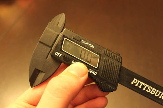
Make sure to set your calipers to zero before measuring.
However, as you might imagine, most parts are much more complicated than a cube. To measure real parts, you’ll have to measure the distance between a lot more points. But the basic principle remains the same: gather measurements and reproduce them in your model.
Doing this will take a decent understanding of geometry. In most cases, you probably won’t physically be able to take measurements of every feature on the part. Some won’t be reachable, while others will have curves or angles with can’t be measured. That brings me to the most important reverse engineering skill you need to learn: how make inferences.
Inferences
When calipers are your only measurement tool, you’ve got to learn how to make some inferences about the part. The inferences you’ll need to make can be broken down into roughly three types: geometric, design intention, and proportions. For most parts, you’ll need to use all three to really get the part modeled right.
Geometric
The easiest kind of inference you can make is geometric. If you can remember your high school math classes, these are the types of problems where you’re given two variables and have to find the third. They’re based on understanding the mathematics of geometry.
Lengths and distances can be easily measured with the digital calipers, so you’ll usually be trying to use geometric inferences to figure out angles and radii. Doing that might seem overwhelming at first, but remember that your CAD software can help you do most of the actual math. You can just draw lines with the information you know, and then let the software fill in the rest.
An example of making a geometric inference about an angle is a basic right triangle. You don’t have to know the angle of the hypotenuse; you just have to know the length of two sides (since you know that one angle is 90°). In the case of the following image, the two sides were 10, and the software filled in the hypotenuse of 14.1421. If you use the Pythagorean theorem—where a2 + b2 = c2 (with c being the hypotenuse)—to check this, you’ll find this is correct. Similar inferences can be made about isosceles triangles, which have two sides of equal length, if you know the lengths of all three sides or two sides and the height.
![]()
DEFINITION
The hypotenuse of a right-angled triangle is the longest side of the triangle. It’ll always be the side whose endpoint doesn’t touch the right angle.
Of course, you won’t just be measuring triangles. However, the good news is that most features with angles can be broken down into simple shapes like triangles.
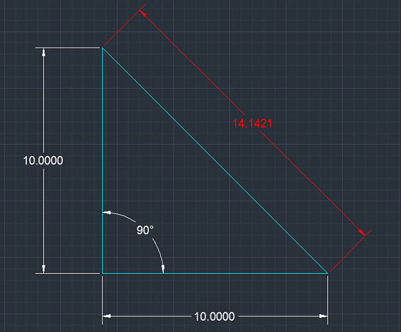
Two sides of this right triangle were entered manually, and the hypotenuse was then determined by the CAD software.
Design Intention
In my humble opinion, design intent is the single most important clue you have when it comes to reverse engineering. The principle behind this is simple: every part was designed by another person. People tend to design parts in fairly predictable ways, so you can make assumptions about the part based on that.
Remember the previous 10mm cube example? Let’s imagine that instead of measuring exactly 10mm for each pair of faces, you actually measured 9.89mm, 10.01mm, and 10.8mm. You could model the part to those exact dimensions. Or you could ask yourself about the designer’s intentions when he created the part.
Is there any reason why he would have given it those exact dimensions? If not, is it more likely that it was intended to be 10×10×10mm? Maybe the differences are actually a simple result of poor tolerances in manufacturing.
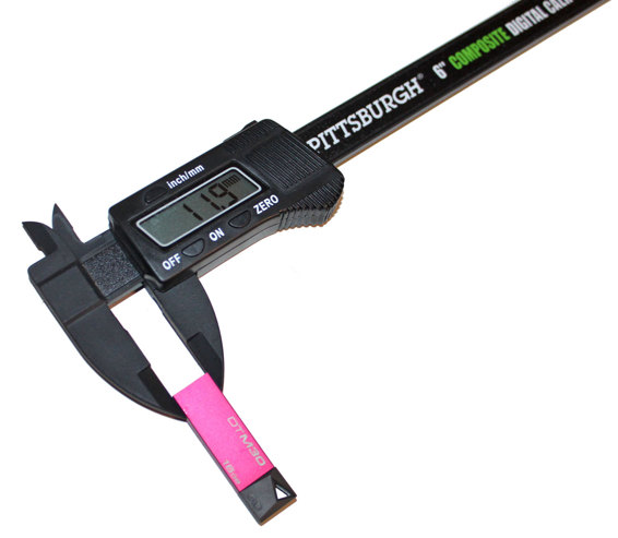
A case of figuring design intention. The measurement was 11.9mm, but we can pretty safely assume it was intended to be 12mm.
Unfortunately, it’s not quite that simple. This time, let’s say the measurements were 9.52mm, 9.53mm, and 9.51mm. You might chalk that up to poor manufacturing. But in reality, the designer might have been working in inches. ⅜ inch equals 9.525mm, so the designer might have intended it to be exactly ⅜ inch.
I bet this is starting to sound like a pretty big headache, right? How can you possibly figure this out when there are so many factors? One of the easiest ways is to first determine the origin of the part.
If it was designed anywhere but in the United States, it was probably designed in millimeters. If it was designed in the United States, it really could go either way. Some industries, especially older ones like the construction and automotive industries, tend to stick to using inches. Some newer industries, like the tech industry, often use millimeters instead. This may not help you determine for sure what units were used to design the part, but it should help.
Linear measurements aren’t the only thing that can be determined based on design intent, though. You can use take that into account for every feature on a part, including curves. Does an angle look like it’s about 45°? There is a very good chance it is. If a radius seems to measure out to about 3mm, you can pretty safely assume that was how it was designed.
The whole idea behind this technique is that you try and think like the original designer of the part. If you were designing that part, would you choose some odd number? Probably not; you’d most likely choose a nice, round number unless you had no other choice. You can use that fact to your advantage when trying to determine how you should model the part.
Proportions
And finally, you can make proportional inferences. These are judgments you can make just by eyeballing the part. To go back to the 10mm cube again, would you really need to take all of the measurements to know it is a cube? You could probably just take one 10mm measurement, and then notice it was a cube and derive the other measurements from that.
As usual, though, most parts aren’t cubes and won’t be this simple. Instead, you’ll be looking at the proportions of the part to help determine the measurements. If there is a rectangular shape and you know that one side is 10mm and the other side looks to be about twice as long, you can pretty safely assume it’s about 20mm.
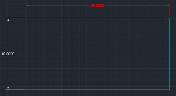
Even if you can only determine one measurement, it’s easy to reasonably infer the other dimension.
That’s because as humans (you are human, right?), we’re pretty terrible at estimating lengths and distances. But we’re surprisingly good at making comparisons, like the proportions between features. I’m not sure exactly why this is, but it’s true.
Whatever the reason, it’s true that humans are much better at judging proportions than they are at judging actual measurements. So use that to your advantage when modeling parts. Don’t try to guess all of the measurements; just guess proportions based on known measurements.
But why would you even need to be guessing at all? If you have those nice digital calipers, why even bother trying to guess proportions? The most common reason is when you’re trying to model a part that you don’t physically have access to, like if you’re reproducing a part from a photo. You might be able to deduce some of the measurements from other objects in the photo, or you might be able to find some measurements online that other people have taken. If that’s the case, you can use the proportions of the part to determine the missing measurements.
You can also use this technique for figuring out dimensions in areas you can’t measure. This is especially true for interior features that just aren’t accessible. Unless you want to try and cut the part in half, you’ll need to make some inferences to get those measurements.
Modeling the Part
You’ve learned all of these methods for determining the dimensions of a part you want to replicate, so now it’s time to model it. There are two ways you can approach this: model it as you measure it, or take all of your measurements ahead of time and then model it. Which approach you take is mostly just a matter of personal preference.
Personally, I tend to model the part at the same time I take the measurements. The main reason is that it’s easier than having to try and write the measurements down in a sensible way. I think it also saves a little time in the process.
But writing down the dimensions can also work well. That way you don’t have to keep switching back and forth between modeling and measuring. You can just take all of your measurements and then switch to modeling.
![]()
HOT TIP
When writing down dimensions, you’ll always want some method for keeping them in order. You can do this by sketching a quick drawing of the part and writing in the dimensions. Or if drawing isn’t your cup of tea, you can assign descriptions to the dimensions. But do something to keep them organized, so you don’t accidentally get them mixed up.
Modeling a part when you only have digital calipers for measurements can be a little tricky. As I went over in the previous sections, there are often a lot of measurements that can’t be taken with calipers. So this is when you’ll want to start using the techniques you just learned.
Start by doing as much as you can with the measurements you were able to take. These will be your “hard” dimensions, which you can be reasonably sure about. Make inferences about the design intent here, like using round numbers unless it makes sense not to.
Once you’ve got all of those hard dimensions in, you can start filling in the blanks. In many cases, the geometry itself will give you the answers. Just like finding the hypotenuse of the triangles, a lot of the dimensions will fill themselves in based on the dimensions you do have. Or more accurately, those dimensions won’t be needed to fully define the model.
Lastly, you’ll need to make some judgment calls to fill in the dimensions you couldn’t measure and can’t be determined with simple geometry. These will usually be things like angles and radii for filleted edges. Luckily, these are the features that lend themselves the most to making inferences.
That’s for a couple of reasons: they usually don’t have to be perfect for the part to function properly, and they’re fairly easy to get right without taking measurements. Fillets are often just cosmetic and aren’t even integral to the function of the part. If they are important, it’s okay because they’re still pretty easy to guess at.
Angles are more likely to be important to the part’s functionality. But they’re also easier to determine. Designers usually stick to 15° increments unless they have a reason not to. You can usually correctly guess the angle just by looking at it.
In the cases where fillets and angles aren’t obvious, your best bet will be trial and error. Experiment with different angles and radii until it looks like the real part. This is where the human knack for comparisons will come in handy. You may be surprised by how close you’ll be able to get the part just by doing this.
Using these methods, you should be able to successfully reverse engineer most of the common plastic parts you come across. You’ll be able to replace broken things around the house, on your car, or anywhere else something plastic breaks. The parts may not come out perfectly the first time you print them, but with a little refinement and practice, you should be able to produce functional replacement parts.
The Least You Need to Know
· Reverse engineering is a very useful skill for reproducing and replacing broken parts.
· Digital calipers are the only tool the hobbyist really needs to take measurements in most cases.
· For dimensions that can’t be determined with digital calipers, you can make inferences and use deductive reasoning.
· When reverse engineering, always consider the fact that the part was designed by another person. Think about what that person would have done while designing it.