Idiot's Guides: 3D Printing (2015)
PART 4
3D Modeling
PROJECT 6
Custom Storage Drawer
Project Time: 1 hour
Your second modeling project is going to be quite a bit more difficult than the first one. You’ll be modeling a custom storage drawer for the storage shelf you printed for project 4. You’ll be able to design the compartments however you wish to suit whatever you’d like to store.
Because this will be harder than the first modeling project, it may be beneficial to spend some time modeling some more basic designs on your own to get a feel for the software before doing this. I’ll also be assuming that you know the basics of using the commands and software, so I won’t be going over each feature in great detail; however, you can check out project 5 if you need a refresher on where to go and what to do in the software. If you’re ready, let’s jump right in!
Open Your CAD Program and Create a New Part
Start by opening your CAD software and creating a new part. As usual, my recommendation is to work in millimeters. This is especially true for this part, because it will be sliding into the existing storage frame.
The frame was designed in millimeters, so the best way to ensure a proper fit is to use millimeters for the new drawer as well. However, if you prefer to use inches, you can divide all of the measurements by 25.4.
Extrude the Body of the Drawer
For this part, you need to start with an extrusion on the top plane. This is because the main body of the drawer will be created by extruding from the side, and you want it to lay down flat on the build plate when you print it. So in this case, the top plane actually corresponds to the front of the part.
The opening in the frame is a rectangle 25mm tall and 100mm wide, with 5mm fillets on the corners. In order to make the drawer fit into the frame, it needs to be slightly smaller than that opening. You can draw the 25×100mm opening with construction lines, and then offset those inside by .50mm. You can then extrude the offset lines by 100mm (the length of the drawer).
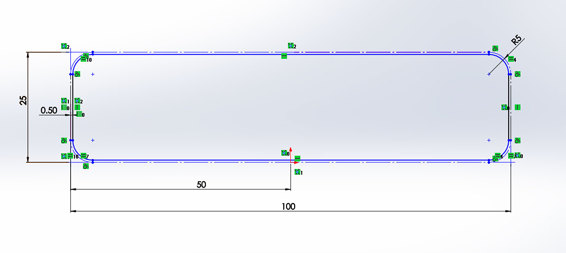
The drawer body is offset .50mm from the 25×100mm opening in the frame.
Cut an Opening for the Handle
The next feature is a cutout that will allow room for the drawer handle. This is so the handle doesn’t protrude from the front of the drawer. This design choice is mostly cosmetic, but will also help the drawer to be printable on smaller printers.
To make this feature, you use the extrude cut command in your software on the top of the part (or the front plane). Make an arc with a 100mm radius, with its endpoints 15mm from each side of the drawer. Next, draw a line connecting the endpoints to make it a closed shape. You can then simply do the cut all the way through the part.
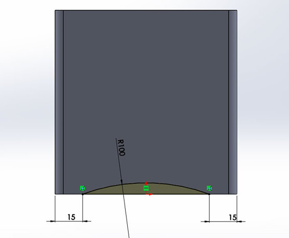
Cut out a place for the drawer handle.
To finish the cutout, add a 50mm fillet to the ends of the cutout. This should be where the endpoints of the arc were. The purpose of the fillets is simply to round the edge and give it a more finished look and feel.
Design the Compartments
This next step is where the customization comes in. You essentially hollow out the drawer and divide it into the desired compartments in one feature. How you divide it up is completely up to you.
However, you should stick to a few basic conventions to make sure the drawer turns out right. In my design, I gave all of the walls a 2mm thickness. This should make it sturdy without being too bulky, so I recommend you do the same.
To do this, start by offsetting the outside lines of the part by 2mm all the way around. Next, draw construction lines to divide it up into the desired compartments. Offset those construction lines by 1mm in both directions (to make the walls of the compartments). Then just trim the overlapping lines so that each compartment is its own fully closed shape.
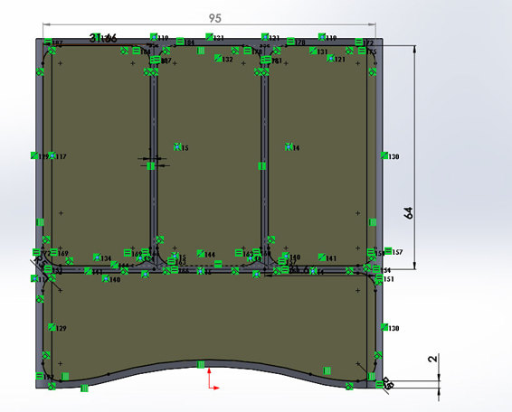
Design the compartments based on your needs. However, it’s a good idea to give the walls a 2mm thickness to make them sturdy.
For the options in the extruded cut feature, choose what’s used to indicate “offset from surface” in your software. You can then select the bottom face of the drawer. Enter 2.00mm, and it will cut the compartments down to 2mm from the bottom face.
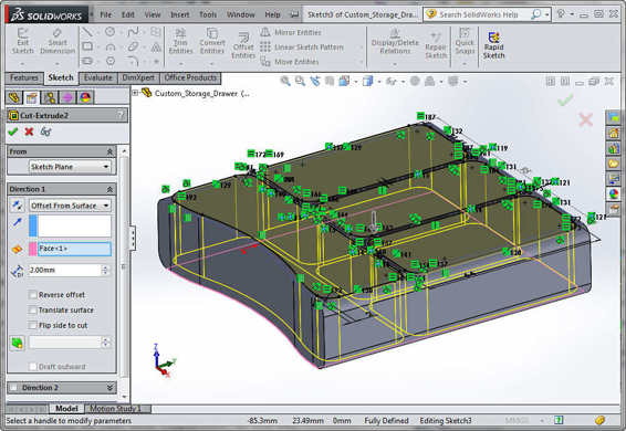
Offset the cut 2mm from the bottom of the drawer.
Add a Rough Handle
Now you can start adding a basic drawer handle. You can use the extrude command in your software, and use the bottom of the drawer as a reference.
![]()
HOT TIP
Why not put the handle in the middle of the drawer? Because doing so would require the use of support material to print the drawer. Extruding it from the bottom will allow the drawer to be printed without any supports, which will improve the quality.
The exact dimensions you use for the handle are up to you. But if you want them to match the other drawers you’ve already printed, you can use the dimensions shown in the following image. It’s a simple rectangle centered on the part that is 30mm wide and protrudes 5mm from the front of the drawer. The outside corners have a 5mm fillet, and the handle itself is 3mm thick.
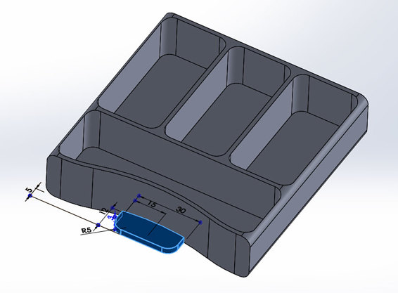
Create a basic handle with the extrude feature.
Add Fillets to Handle
Adding fillets to the handle serves two purposes: to improve the aesthetics and to strengthen the handle. The aesthetic reasons are a pretty obvious: filleted edges just look nicer. But they’re also important because they make the handle stronger. The gradual transition takes away the weak point that would otherwise be present at the 90° edges.
In this case, two different fillets are used. On the vertical edges on either side of the handle, 10mm fillets are used. On the top of the handle (the horizontal edge), a 3mm fillet is used. This gives it strength while still leaving a flat spot for you to grip when opening the drawer.
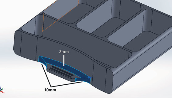
Add fillets to improve the look and strength of the handle.
Add Ridges for Grip
The final two features you’ll create are there to make a couple of small ridges on the handle. Their purpose will be simply to make the handle easier to grip when you’re opening the drawer.
The first step to making these is a simple extrusion on top of the handle. I made mine by drawing 1mm-diameter circles 20mm apart, and then connecting them with lines on the top and bottom. The insides of the circles can then be trimmed away. The center of the first ridge is 2mm from the edge of the handle, and the second ridge is 3mm from that.
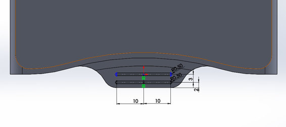
Add a couple of small 1×21mm ridges to the top of the handle.
The final feature is .25mm fillets all the way around the top and bottom edges of both ridges. This is just to smooth out the ridges and make them more comfortable for your fingers.
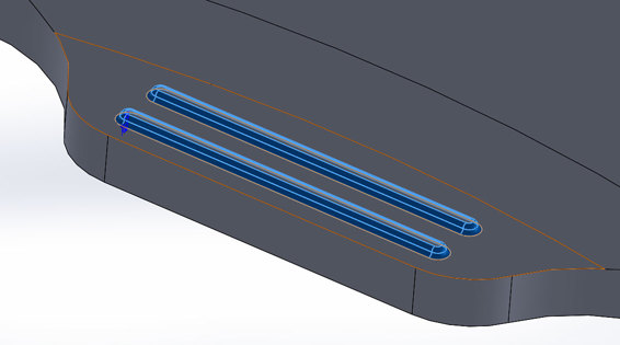
Fillet the top and bottom edges of both ridges.
Export the .STL File and Print
With the part finished, you can export it and print it. Export the .STL file at high-quality settings to make sure you retain the curves of the model. You can then just print it using the same settings you used to print the drawers in project 4 and allow to cool before removing.
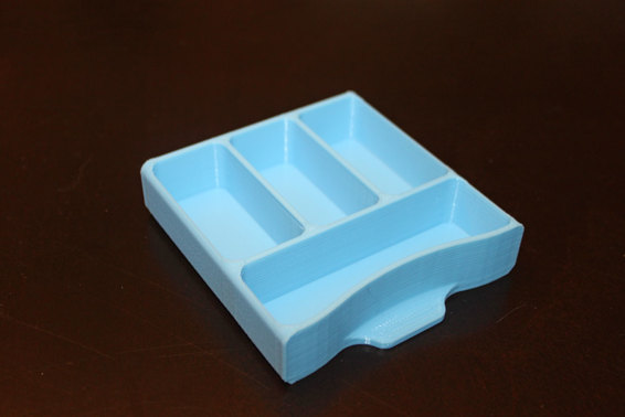
Your finished drawer should look something like this, but with whatever compartment layout you decided to model.