Idiot's Guides: 3D Printing (2015)
PART 2
All About the Hardware
CHAPTER 6
Movement Components
In This Chapter
![]()
· How linear motion works in 3D printers
· Using stepper motors for precise movement
· How threaded rods make 3D printers more affordable
· Basic connection components
The frame of a 3D printer is the foundation for every other part, which makes it very important. But even the best frame in the world is useless without some kind of mechanical system for movement. The goal for all 3D printers is to provide linear movement on each axis. The specific way this is accomplished can vary based on the particular printer, but most use the same fundamental parts and systems.
In this chapter, I go over the pieces that accomplish the movement needed with a 3D printer.
Components for Smooth Linear Motion
With any kind of linear motion system, it’s important that the motion be constrained to a single axis in one dimension. Any kind of movement outside of that one dimension is almost always considered to be undesirable, because it introduces unintended movement in the other axes.
Furthermore, the motion on that one axis should be as smooth and frictionless as possible. The less friction there is in the system, the less force is required for movement on that axis. Friction in the system increases the power required for motion on that axis and can create inconsistencies in the movement.
For smooth linear motion, regardless of the particular machine, the most common setup is a smooth rod or rail with bearings on the moving part. This works in exactly the way that you would expect: the bearings reduce friction in the movement, and the rod or rail gives the bearing a smooth and straight surface to ride on. The concept is simple, but the individual components are still important.
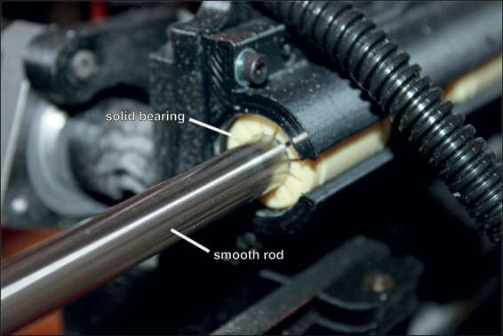
Smooth rods and solid bearings on a Lulzbot TAZ 4.
Rails and Smooth Rods
Smooth rods are exactly what they sound like: a straight cylindrical metal rod that is polished smooth. Rails are similar, except they don’t need to be cylindrical and can be flat instead. Rails are often used when they need to provide some level of structural support, while rods generally aren’t used as part of the structure. However, rods have the advantage of constraining movement in two directions with a single bearing, while rails often need two or three bearings to do the same.
![]()
FASCINATING FACT
In some 3D printer designs, the aluminum extrusion that makes up the frame is also used as the rail for moving parts to ride on. One or more bearings make contact with the surface of the extrusion, allowing parts like the print bed to slide across it. These designs are usually very economical but may not be capable of the same quality as designs that have dedicated smooth rods.
Whether it’s a rod or a rail, there are a few characteristics that are important for them to work well:
· The smoothness of the surface
· The hardness of the surface
· The straightness of the part
· The stiffness of the part
· The diameter of the part
The smoothness of the surface is important for reducing friction, of course. But the other qualities need a little more explanation.
The importance of surface hardness, for example, may not be immediately obvious. After all, it’s not like you’ll be hammering it or anything. But what you will be doing is continuously running a bearing back and forth along the length of the part. Over time, the bearing can gouge the surface, making the surface significantly less smooth. And as you know, without a smooth surface, friction can be a problem.
How straight the rod or rail is also important for a reason that should be readily apparent—if it’s not straight, movement won’t be perfectly linear. But what may not be apparent is exactly how straight it needs to be. In manufacturing, straightness has its own specific geometric tolerance (a specification for how closely the real part must match the design). This tolerance is very tight in rods and rails manufactured for use in linear motion systems but may not be quite so strict for rods and rails that are specifically made for this purpose. For that reason, it’s important to be careful about choosing those components when building a 3D printer.
Luckily, the reason rods or rails need to be stiff is straightforward. Rods or rails used in linear motion systems simply can’t have any flex in them under the intended loads. This and the other characteristics mean that only a few materials are both suitable for the application and affordable.
Of those materials, the most commonly used seems to be hardened stainless steel. When manufactured properly, this material can possess all of the desired characteristics while also being corrosion resistant and fairly inexpensive. Other materials can be used (and may even be necessary in some industries), but for 3D printers, there doesn’t seem to be any reason to use anything else.
The last factor, particularly for smooth rods, is the diameter of the rod. While the rods don’t generally provide structural support for the frame, they do need to support the weight of the moving parts. How much weight they need to support and how long they are will determine the diameter needed for the rods. This varies from one 3D printer to another, but smooth rods are usually somewhere between 8mm and 12mm (although they can be bigger or smaller in some cases).
Bearings
As far as mechanical components go, bearings are some of the most fundamental parts in use; in fact, they’re almost comparable to fasteners like nuts and bolts. Anytime there are moving parts, bearings practically become a necessity. The purpose of a bearing is simply to reduce friction between moving parts. There are two basic types of bearings: solid bearings (usually called bushings) and roller bearings.
A solid bearing doesn’t have any rolling elements and is usually meant to be lubricated. The bearing itself is made of either metal or plastic. When it’s made of metal, the metal should be of a different type than the shaft it’s in contact with. Generally, a softer metal is ideal so the bearing wears instead of the shaft. Combined with a lubricant, a solid metal bearing can be satisfactory for reducing friction.
![]()
HOT TIP
When looking at bearings, be aware that many different names are used to describe essentially the same things. For example, solid bearings are often called sleeve bearings. This is a result of their long history, their use in many different industries, and very minute differences between similar bearings.
Solid plastic bearings are made from self-lubricating types of plastic like nylon, Delrin (the trade name for a strong, self-lubricating plastic), or some variation of polyethylene (like UHMW, HDPE, or LDPE). These types of plastics have very low coefficients of friction, allowing them to be used for solid bearings without any lubricant. This makes them ideal in mechanical systems where lubricant is impractical, like in sealed systems or when lubricant can damage the mechanisms.
The primary advantage of solid bearings has traditionally been cost. Because there are no small moving parts, they’re inexpensive to make, which reduces the overall cost of the machine being built. They were also the first type of bearing used, before the Industrial Revolution made roller bearings feasible. Even now, solid bearings are still the most common type of bearing in use.
But when a mechanism needs to have as little friction as possible, roller bearings are the answer. These types of bearings, often called ball bearings, usually have three components: an inner sleeve, an outer sleeve, and a number of small balls between the two. As one sleeve is rotated, it rolls on the balls. For linear ball bearings, the shaft itself acts as the inner sleeve and the balls roll between the shaft and outer sleeve.
Both solid bearings and roller bearings come in two basic styles: linear and rotational. The application determines which kind is needed. If the moving parts only need to rotate on a single axis, rotational bearings are used. If linear motion is needed, like in a 3D printer, linear bearings are used. Therefore, no matter the type of bearing, your printer will need them to be linear.
Stepper Motors
With all of this motion happening, there has to be some kind of electric motor involved to actually make things move. There are many types of electric motors that are technically capable of providing this motion. However, there is one type in particular that is perfectly suited to the task: a stepper motor.
The key characteristic of a stepper motor is its ability to rotate very precisely. A plain old electric motor will simply rotate when electricity is applied, and will rotate faster as the amount of electricity being applied is increased. This simplicity means that a regular electric motor is very efficient, but it also means they’re difficult to precisely control. This is what stepper motors were created specifically to address.
A stepper motor is a type of electric motor constructed specifically to allow precise control. That precision is important for producing accurate and detailed prints. It does this by rotating in a series of steps, instead of just rotating continuously when electricity is connected. A common stepper motor, like what is used in most 3D printers, can have 200 steps for every complete rotation of the output shaft.
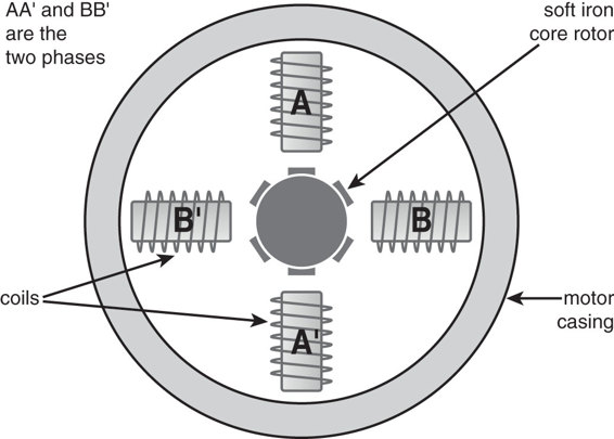
The internal construction of a stepper motor. Notice how the teeth of the rotor are designed so that when they are aligned to one phase, they are misaligned to the other.
![]()
HOT TIP
While stepper motors are by far the most common type of motor for 3D printing, there are other options. Continuous-rotation servos can be used and are also fairly accurate. And, in a method similar to what paper printers use, a plain electric motor can be used in combination with an encoder strip to monitor position. But the ease of use and high precision of stepper motors continues to make them ideal for 3D printing.
Because the stepper motor can move a single step at a time, that means it can rotate the output shaft precisely 1.8° for each step (for a 200-step motor). Additionally, a technique called microstepping can be used to reduce each step even further. Microstepping is handled by the stepper motor controller, and many controllers are capable of 1/16 microstepping. That means each individual step can be broken up into 16 microsteps.
At 16 microsteps on a 200-step motor, the output shaft is capable of being positioned at 3,200 individual places per rotation. That’s one position every .1125°, an incredible level of precision that simply isn’t possible with any other kind of electric motor.
This high level of precision is what makes stepper motors ideal for machines like 3D printers. Even without using microstepping, the accuracy is very high. If a full rotation of the stepper motor output shaft moves an axis 1mm, each step will move it .005mm. That means each axis of the 3D printer can be positioned anywhere within a tolerance of +/- .0025mm, and that can be made significantly more accurate with microstepping.
With that kind of accuracy, it’s easy to see why stepper motors are so popular, and why they’re used in virtually all 3D printers. But how does the rotational movement of a stepper motor translate into the linear motion needed for 3D printing? That’s where belts, pulleys, and lead screws or threaded rods come in.
Belts and Pulleys
Belt and pulley systems are one of the oldest mechanical systems in history and have a wide range of uses. Aside from simply transmitting motion from one pulley to another, they can be used to reduce a drive system to gainmechanical advantage.
![]()
DEFINITION
Mechanical advantage is the amplification of force with the use of a tool or mechanical system. This is usually achieved by trading movement distance for force. A lever is the most basic example of this, because if one side of the fulcrum (pivot point) is twice as long as the other, it will double the force exerted (though it will also double the distance it needs to be pushed). This same basic concept is applied in a vast array of machines using things like gears, pulleys, screws, and so on.
In its most basic setup, a belt and pulley system is very simple. One pulley is driven by a motor of some kind, and a belt connects it to a second pulley to transmit the rotation of the first pulley to the second. If both pulleys are the same size, the drive system has a 1:1 ratio and the purpose of the system is simply to transfer power.
Mechanical advantage is achieved when the pulleys are of different sizes. If the first pulley (the drive pulley) is smaller than the second, the resulting output has more torque but less speed. When the system is reversed and the first pulley larger than the second, the output has greater speed but reduced torque.
Multiple pulleys can be used to gain even greater reductions and significant mechanical advantage. Systems like that are what allow a person to lift loads many times their own weight. In the same way, such a system can allow a relatively low-torque (but high-speed) motor, like an electric motor, to handle high loads.
However, while some printers use mechanical advantage in their designs (especially for the cold end), others keep power transmission at a 1:1 ratio. To move the print bed, for example, a pulley is attached to the output shaft of a stepper motor and a second pulley is mounted on the opposite end of the axis. A belt is looped around them and attached to the print bed in the middle. As the output shaft of the stepper motor spins, it pulls the belt and therefore moves the print bed along the axis.
As far as pulley systems go, this is a very simple setup. However, mechanical advantage can be introduced by changing the size of the drive pulley. The bigger the drive pulley is, the further it will move the print bed per revolution. If the speed at which the stepper motor turned remained constant, the size of the drive pulley would determine the speed and torque of the print bed movement. A large drive pulley would move it quickly but with reduced precision and torque. A small drive pulley would move it slowly but with higher precision and more torque. This allows the printer manufacturer to prioritize speed or precision in their designs.
While the setup is pretty much standard, the physical design of the belts and pulleys on 3D printers can vary. They can be as low tech as a fishing line acting as a belt, wrapped around a drum acting as pulley. Or they can be high-tech parts designed specifically for this purpose. Most commonly, though, 3D printer manufacturers use simple toothed belts and pulleys.
These toothed belts and pulleys are fairly similar to a car engine’s timing belt. It’s a rubber belt with teeth on one side that mesh with pulleys that also have teeth. This setup is ideal because it doesn’t slip, the belt doesn’t stretch, and it’s affordable.
Belt and pulley systems are great for horizontal movement (the X and Y axes), where the belt doesn’t have to bear any weight. All it has to do is pull one way, and then back the other way.
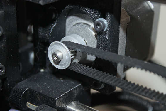
This is a common GT2 belt and pulley setup.
Weight-Bearing Components for Converting Motion
When rotational motion (for the vertical Z axis) needs to be converted into linear motion, and there is a significant load on the system, lead screws or threaded rods (which are inexpensive alternatives to lead screws) are the best option. There are two reasons lead screws are ideal for such a situation: they can provide a significant mechanical advantage without complicated pulley or gear systems, and the lead screw itself can bear the weight of the components it’s lifting.
A lead screw drive system is a lot like a bolt and nut; in fact, that’s pretty much what it is (physically speaking). When you rotate the bolt but don’t allow the nut to spin with it, it pushes or pulls the nut along the rotational axis. A lead screw works in the same way: the stepper motor turns the lead screw, which pushes or pulls the nut up and down on the Z axis. The nut is attached to whatever components need to be moved in the Z axis, allowing the stepper motor to lift or lower them as it turns.
Lead Screws
Lead screws come in all kinds of sizes to suit the requirements of the machine being built. They come in various diameters and pitches (metric and standard) with one start threads, two start threads, or even more. The diameter is factor in the strength and stiffness of the lead screw and can help the smooth rods constrain movement to a single axis. The thread pitch determines the mechanical advantage of the drive, because it is what controls how far the nut is moved per rotation of the lead screw.
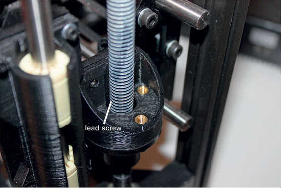
A lead screw and nut linear motion system for the Z axis.
![]()
DEFINITION
The pitch of a thread is the distance from one thread to the next. This is what determines how far the screw and nut will move (relative to each) with one full rotation. For example, an M8 screw has a standard pitch of 1.25mm. So if you have a lead screw with an M8 thread, every full rotation of the lead screw will move the nut 1.25mm.
Despite how common and utilitarian lead screws are, they are still very precisely made parts. The complexity of the specifications of lead screws (they need to be smooth, straight, hard, and stiff), along with the precision required when machining them, makes them very expensive. Many 3D printer designs require two of them (one on either side of the printer), which just adds to the bill. In fact, this cost is so high that lead screws can end up being the most expensive parts on a consumer 3D printer.
With such a high price for such a basic part, 3D printer manufacturers and DIY builders have tried to find another solution.
Threaded Rods
In an effort to reduce the cost of 3D printers, many designers have chosen to substitute threaded rods for lead screws. A threaded rod is essentially a very long headless bolt. The general purpose of a threaded rod is for fastening, which is done by threading a nut onto either end.
Because threaded rods are only intended to be fasteners, the manufacturers put little importance on the qualities that are considered necessary for lead screws. The result is a part that isn’t particularly straight or hard and doesn’t have perfectly machined threads. A threaded rod is just good enough to thread a nut onto while being sort of straight.
Manufacturers are able to make threaded rods at very lows costs while still maintaining the required precision. That cost is so low that threaded rods are generally about 1/10 the price of lead screws. At that kind of price, it’s easy to see their allure to a 3D printer manufacturer trying to build an affordable consumer printer.
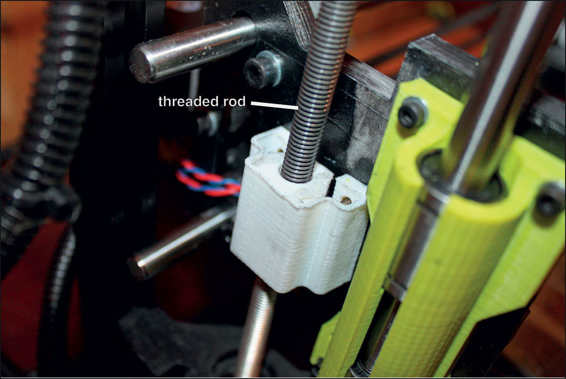
A threaded rod used in place of a lead screw.
But there is a pretty glaring problem here: if threaded rods work, why would anyone spend the extra money on lead screws? From the point of view of those who use threaded roads, there are a couple of different answers to that question.
One possibility is that lead screws are necessary for certain kinds of machines but not for 3D printers. The argument is that the loads being put on the lead screw by a 3D printer are small, and the precision required is fairly low. If a real lead screw makes a difference at all, it’s very subtle.
Another possibility is that there is a perceptible difference between lead screws and threaded rods but that it can be designed around. The idea here is that lead screws are only necessary if they’re firmly constrained, in which case they’re acting kind of like a smooth rod to restrict movement perpendicular to the Z axis. But because there are already smooth rods for this purpose, it is unnecessary for the lead screw to provide that function. Because the threaded rod doesn’t have to restrict perpendicular movement, it’s not necessary for it be perfectly straight. All that matters is that it doesn’t inadvertently introduce perpendicular movement.
At this point, there is very little evidence for or against the effectiveness of threaded rods that isn’t just anecdotal. The quality of a 3D-printed part is the result of the complex interaction of many different pieces of hardware and many settings in software. It’s difficult to control every other factor while only changing from lead screws to threads in order to scientifically test this. However, the anecdotal evidence seems to suggest that threaded rods can work well if the design is done properly.
Attachment and Connection Components
Whether lead screws or threaded rods are being used, there always needs to be a way to connect the stepper motors to them. And, once that stepper motor is spinning, there needs to be a way to translate the turning screw into movement on the Z axis. Both of these problems have specific parts designed to solve them: a coupler connects the stepper shaft to the screw, while a nut attaches parts to that screw so they can be moved along the Z axis.
Couplers
The job of the coupler is rather unspectacular: it’s just there to connect one shaft to another. However, various kinds of couplers exist to serve all sorts of specific purposes. There are couplers designed to flex and others that are designed specifically to minimize flex. Some couplers are supposed to be springy to absorb shock in the shaft, while others are designed to avoid this.
In the case of 3D printers, which type of coupler is ideal depends on whether lead screws or threaded rods are being used. If a lead screw is being used, it’s reasonable to assume it is both very straight and very stiff. If that’s the case, the coupler should be solid and stiff as well, so that movement is smooth and constrained to that rotational axis.
![]()
FASCINATING FACT
In many RepRap 3D printer designs, the coupler is simply a small piece of flexible plastic tubing that fits over the stepper motor shaft and the threaded rod. The tubing is then zip tied on both ends to keep it tight. This low-tech solution is both very inexpensive and surprisingly effective.
However, if a threaded rod is being used, it’s very likely it’s not straight at all. It’s probably slightly bent and maybe a little bit flexible itself. In such a case, it’s preferable for the coupler to be flexible in order to absorb the movement caused by the threaded rod not being straight.
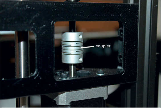
A standard coupler meant to allow some flexibility.
The coupler itself can be made from a variety of materials and in a variety of styles. Aluminum, steel, and brass are all popular materials, and types of plastic can be used as well. Designs can be a simple straight tube, can be cut in a helix to absorb forces along the rotational axis, or can be cut with slots to absorb forces perpendicular to the rotational axis. Most will have some sort of set screw or clamping apparatus to lock the coupler onto both shafts, but even that may change in some specific circumstances.
Nuts
A nut is a simple part that is threaded onto a threaded rod or lead screw. It can be a basic hex nut like the kind you curse whenever you have to do work on your car, or it can be a specialized type of nut meant specifically for linear motion systems.
Like most other components, materials can vary. However, it’s widely considered to be necessary for the nut material to be softer than the material of the lead screw or threaded rod. The reason is basically the same as why bearings and bushings are made of softer metals: so that they wear first. As expensive as lead screws are, it would be a real shame if the threads got worn down by a 50-cent nut. It’s much better to replace the inexpensive nut as it gets worn down.
With that said, nuts that are used on 3D printers aren’t often as simple as the kind you buy in bulk at the hardware store. Because these nuts are meant for power transmission, not fastening, they have two unique qualities:
· They need to have some kind of mount on them.
· They should resist backlash.
The need for a mount is pretty straightforward; there has to be way to attach the parts you want to move. For this reason, there are nuts made with mounting flanges so the moving parts can be connected. These mounting flanges come in various sizes, shapes, and hole patterns, but those details aren’t really relevant to their operation.
What is relevant to the operation of a screw drive system is backlash. Backlash, in this context, is when the nut slightly shifts when the rotation of the screw reverses. The direction of movement suddenly changes and the nut moves slightly because of the space between the threads. To be clear, this is a very small shift, comparable to the movement you feel if you try to wiggle a nut that’s threaded onto a bolt. But I’m talking about a machine that is trying to move with very high accuracy, so even a slight shift can affect that.
The solution to this problem is the creatively named anti-backlash nut. A very basic design for this consists of four parts: a housing, two normal nuts, and a spring. The housing fits over the nuts and keeps them from moving independently of each other, while the spring sits compressed between the two nuts. Because the spring is compressed, it’s constantly pushing out on both nuts. This ensures that the top surface of one nut’s threads is in contact with the screw, while the bottom surface of the other nut’s threads is in contact. This effectively eliminates backlash, because when the direction is changed, one of the nut’s threads will always already be in contact with the screw.
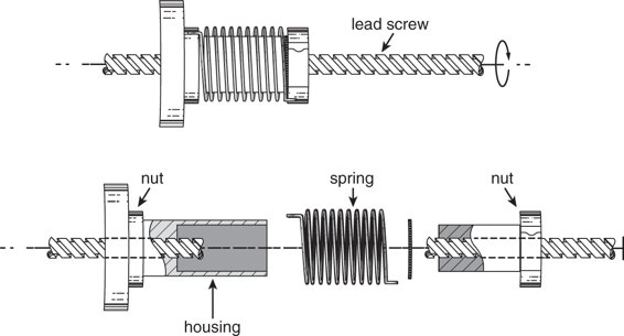
A simple anti-backlash nut design.
With all of this detail on the nuts and screws of 3D printers, it may seem like they’re very complex machines. And in a way, they are. But the reality is that most machines are at least this complicated when you really get into the details, and 3D printers aren’t an exception.
The Least You Need to Know
· Smooth rods, rails, and bearings are used to provide smooth, low-friction movement.
· Stepper motors are unique types of electric motors that are perfectly suited for 3D printing because of their precision.
· Belts and pulleys are often used to drive the X and Y axes of 3D printers, while lead screws are used to drive the Z axis.
· Threaded rods can be used in place of lead screws, but there is some ambiguity about how well they do the job.
· Couplers are used to attach lead screws or threaded rods to stepper motor shafts, while nuts (anti-backlash or otherwise) are used to attach the moving parts to the lead screws.
All materials on the site are licensed Creative Commons Attribution-Sharealike 3.0 Unported CC BY-SA 3.0 & GNU Free Documentation License (GFDL)
If you are the copyright holder of any material contained on our site and intend to remove it, please contact our site administrator for approval.
© 2016-2026 All site design rights belong to S.Y.A.