Idiot's Guides: 3D Printing (2015)
PART 2
All About the Hardware
CHAPTER 7
The Extruder
In This Chapter
![]()
· How FFF extrusion works
· Different types of cold ends and hot ends
· Changing nozzles
· When to use a print fan
· The benefits of multiple extruders
Extrusion is the key to FFF (and FDM) 3D printing. It’s what separates the FFF printing process that is so common in consumer printers from the other processes that are used in more expensive 3D printers. Extrusion itself is used in many ways in manufacturing, but the technique has been fine-tuned for 3D printing in FFF printers. In this chapter, I cover how extrusion works and how it affects your prints.
What Is Extrusion?
In general terms, extrusion is any process used to eject material with a specified cross-section. Extrusion in manufacturing can be used to create a wide range of parts, with the major restriction being that the cross-section of the part has to remain constant.
With FDM/FFF 3D printing (see Chapter 2), extrusion is the process used to actually deposit new plastic onto the print bed. It also refers to how the aluminum frame pieces that are often used to build 3D printers are created.
Complex shapes are possible with extrusion in manufacturing, but the process is much simpler on 3D printers. Plastic is extruded out of a plain circular nozzle, resulting in a very simple cylindrical extrusion.
To extrude plastic, FFF printers use a system known as an extruder that feeds filament into a hot end to be melted, and then deposits it on the print bed. How exactly this is done varies a little bit depending on the particular 3D printer, but they’re actually all pretty similar.
The Cold End
The system begins with feeding the filament, a task handled by a mechanism called a cold end. The cold end pulls filament and pushes it into the hot end. As more filament is pushed into the hot end, the melted filament is squeezed out through the nozzle for deposition onto the print bed. So the purpose of the cold end is easy to understand; it’s just there to feed the filament. But it’s more than just that; it needs to be able to feed the filament precisely and consistently.
![]()
HOT TIP
The terminology used for various parts of 3D printers can often be a bit confusing. Sometimes, different terms are used to describe the same part based on the manufacturer, plus the hobbyist nature of 3D printing has led to parts being developed simultaneously by independent designers.
The cold end is one example of this confusion. The cold end is what feeds filament into the hot end, which in turn melts the filament. However, the cold end is often referred to as the extruder instead. This is made even more confusing, because extruder is the term used to describe the entire system (cold end and hot end). To try and avoid any confusion in this book, I’ll refer to the individual mechanisms as the cold end and the hot end, and the system as a whole as the extruder. But be aware that these terms may be used differently depending on the source.
It’s important that the printer be able to extrude exactly the right amount of filament in order for the print quality to be good. As I mentioned in Chapter 3, the layer thickness is determined in part by how much filament is being extruded. The slicing software knows exactly how much filament is being pushed out of the hot end at any given time and calculates the extrusion as needed.
In order for the slicer to be able to make usable calculations, the cold end has to be capable of consistently feeding exactly the predicted amount of filament at all times. If the filament is fed inconsistently, the calculations being made by the slicer software become useless, resulting in either overextrusion or underextrusion (both of which will yield a poor-quality print).
For this reason, the extruder has to be properly calibrated. Extruder calibration is absolutely necessary to make sure the correct amount of filament is being extruded. This is a simple matter of making sure the amount of filament being fed into the hot end matches the predicated amount and adjusting the feed rate if it’s not right.
To do this, cold ends use stepper motors for precise control—the same type of stepper motors that are used for moving the axes of the 3D printer. The stepper motor turns some sort of hobbled bolt or drive gear that has serrations to grip the filament, and a bearing on a spring provides tension. The filament is held tight between the bearing and hobbled bolt, and as the stepper motor turns, it pushes the filament into the hot end.
The setup for this mechanism depends on what kind of cold end is being designed, and there are two distinct types: direct feed and Bowden.
Direct Feed
The most common type of cold end is the direct feed style (not to be confused with direct drive, which I discuss later in this chapter). It’s called a direct feed cold end because the hot end is located right below it, and filament is fed directly from the drive gear into the hot end.
There are two advantages to this direct feed style: it’s a simple setup, and it reduces the chances of the filament binding or bunching before it enters the hot end.
The simplicity of the setup is probably the primary reason why direct feed cold ends are so popular and why almost all consumer 3D printers use them. The motor and drive gear are mounted right above the hot end, and the filament is pulled from a spool, which can be mounted anywhere on or around the printer.
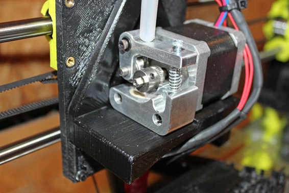
A direct feed cold end made by Printrbot.
But as consumer 3D printer technology has matured and our understanding of it has improved, it has become apparent that the real benefit of a direct feed cold end is that it lessens the likelihood of the filament bunching. As flexible filament (a material which feels similar to rubber or silicone) and 1.75mm filament have gained popularity, it’s become more of a problem for filament to bunch up and jam before it actually enters the hot end. Having the drive wheel right above the hot end to push the filament doesn’t leave any space for it to bunch up.
Bowden
Bowden-style cold ends are named after a mechanism called a Bowden cable. A Bowden cable is a push/pull device that consists of a hollow tube with a solid or stranded cable running through it that lets you transmit pushing or pulling force over a distance with a flexible cable. This mechanism is used in all sorts of things, including airplane controls, bicycle brakes and gear shifters, motorcycle clutches, throttle cables, and many other things.
![]()
FASCINATING FACT
There is some debate over who Bowden cables are named for. The original Bowden mechanism was invented and patented by Ernest Monnington Bowden, but Sir Frank Bowden (founder of the Raleigh Bicycle Company) is often given credit for its invention. The two men were not related, but their common last name is surely a factor in the confusion. Ernest Bowden actually licensed his patent to Sir Frank Bowden for use in his bicycle brake systems, which just further confuses things.
A Bowden cold end works on a similar principle. Instead of having the drive mechanism right above the hot end on the extruder carriage, it’s located elsewhere on the 3D printer. A hollow and flexible tube (usually made from a low-friction plastic like polytetrafluoroethylene [PTFE]) runs from the cold end to the hot end, and the filament is pushed through it. This setup serves one very specific purpose: to remove mass from the extruder carriage.
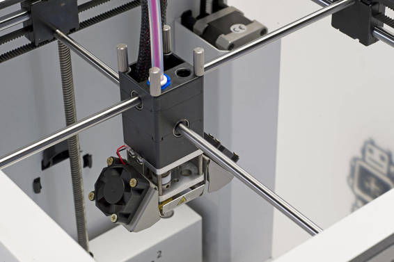
A Bowden cold end on an Ultimaker 2.
(Courtesy of Ultimaker)
Having a smaller and lighter extruder carriage is advantageous for two reasons:
· It reduces the overall size of the 3D printer.
· It improves print quality.
It reduces the size of the printer because the extruder carriage doesn’t need as much room to reach the ends of the print bed. How it affects print quality is a little more complicated.
Moving a large amount of mass around quickly is a difficult task. Every time the direction of the moving mass changes, the printer has to overcome the inertia of that mass. But unless you’re printing at slow speeds, the 3D printer never completely overcomes the inertia and it slightly overshoots the intended stopping point. When it overshoots, it results in uneven edges around features, making fine details impossible to print well.
A large, moving mass also creates vibrations as the extruder carriage moves back and forth. This results in an effect called ghosting, where faint outlines of a feature show up on the surfaces near those features. So the mass of the extruder carriage ends up having a pretty significant effect on the output quality of a 3D printer.
Bowden style cold ends solve this problem by removing as much mass as possible from the extruder carriage. It takes the weight of the stepper motor and drive gear and moves it to a stationary location. But, of course, this setup does have its drawbacks.
In the previous section, I explained how direct feed cold ends reduce the chances of filament bunching before it enters the hot end. And that’s exactly the problem with Bowden cold ends. With such a long distance between the drive gear and the hot end, there is a lot of room for the filament to bunch and jam. This makes it difficult to use 1.75mm filament and almost impossible to use flexible 1.75mm filament.
Direct Drive vs. Geared
Whether a Bowden or direct feed cold end is being used, there is still the option of pushing the filament either with a drive gear connected directly to the stepper motor shaft or with a hobbled bolt connected to a gear system. As I’m sure you’re sick of hearing by now in this book, each has its advantages and disadvantages.
Direct drive extruders use a drive gear that is mounted onto the stepper motor shaft. This is the absolute simplest way to design an extruder, which is always a good thing. However, it takes a lot of force to push filament through a hot end. Because they are light and compact, direct drive extruders have difficulty handling the force needed for 3mm filament.
On the other hand, geared extruders use a pair of gears to gain mechanical advantage and the torque needed to force 3mm filament through the hot end without difficulty. The disadvantage, of course, is that the gears add size and weight to the extruder carriage, although that’s not a problem for Bowden extruders since the cold end doesn’t move.
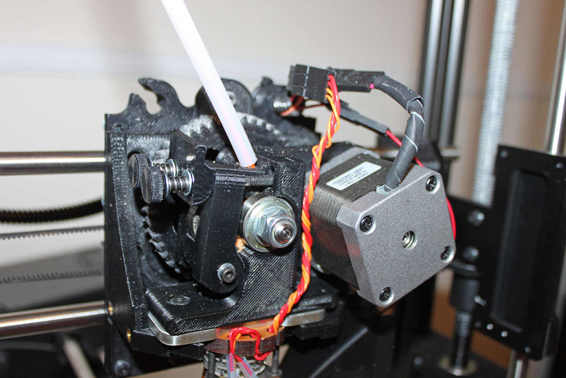
A Greg’s Wade Reloaded geared direct feed cold end.
The Hot End
As you’ve learned in previous chapters of this book, the hot end serves one very specific purpose: to melt the plastic filament. It must melt the filament very quickly in order for the 3D printer to print at a reasonable speed. For that to happen, the temperature of the hot end has to be very high.
Exactly how high the temperature needs to be depends on the material being printed, the filament manufacturer, and even sometimes the specific batch of filament. For the most common materials, however, the hot end needs to be operating at temperatures between 180°C and 250°C. To put that into perspective, that’s approximately the same temperature as the hot oil in a deep fryer.
An Ubis hot end, which is used on Printrbot 3D printers.
Some materials, however, require much hotter temperatures. For example, polycarbonate is an extremely tough plastic that requires temperatures of 300°C or more to print well. With such high temperatures, it’s easy to see that some special hardware is required. In order to heat up the hot end, two specific electronic components are needed: a thermistor and a heating element.
Thermistor
A thermistor is a type of variable resistor similar to a thermocouple that changes based on how hot it is. The term thermocouple is often used incorrectly to describe the thermistor used in 3D printers, but they’re actually entirely different components. They work similarly, but thermistors are generally more accurate and are better suited for 3D printers.
The thermistor is mounted onto the hot end at the point where the filament is supposed to be melted. As the hot end heats up, the resistance of the thermistor changes. The control board of the 3D printer monitors this resistance change and uses it to calculate the temperature of the hot end. In essence, it’s basically just a very accurate thermometer that can be read by the 3D printer.
![]()
DEFINITION
A thermocouple is a type of temperature-measuring device used in a wide range of industries. It’s inexpensive and doesn’t require a power source, which makes it ideal for some applications. However, thermocouples aren’t very accurate, which generally makes them unsuitable for use in 3D printer hot ends.
Thermistors are accurate to within a fraction of a degree when properly set up. Because thermistors are made by a variety of manufacturers, sometimes for slightly different applications, the proper setup can vary. To solve this problem, 3D printer firmware comes with information for many different thermistor models in order to make the temperature reading as accurate as possible. With an accurate temperature reading, the 3D printer can precisely control how hot the hot end is. This allows the user to set the temperature as necessary for a specific type of filament.
But getting any accurate temperature reading is only half of the equation; the 3D printer also needs to be able heat up the hot end to the desired temperature using a heating element.
Heating Element
The heating element for a hot end is a much more general type of component than the thermistor. Virtually all electronic heating elements work in the same way, whether it’s for an electric space heater, an electric stove, or the hot end of a 3D printer. All of these devices use a method called resistive heating.
Resistive heating is an extremely basic process, and is really just a fundamental property of electronics in general. When current passes through a conductor, it heats the conductor. If the voltage in a circuit remains constant, the heat of a resistor increases as the resistance decreases. The current draw also increases along with the heat. So when the objective is to heat something up, like a hot end, a heating element with a low resistance is used.
That low resistance draws a high current, and therefore a lot of power needs to be dissipated by the source of the resistance (in this case, the heating element). That power is dissipated in the form of heating up the heating element, and in turn the hot end.
Physical Design and Makeup
The combination of the thermistor and the heating element allows the 3D printer to set the temperature of the hot end very accurately. When the 3D printer is first turned on and the hot end is still cool, constant voltage is applied to the heating element to heat it up as fast as possible. As it gets close to the desired temperature, that voltage is pulsed to slow down the heating process until it reaches the correct temperature.
Once it’s at the correct temperature, the printer monitors the thermistor and turns the heating element on and off as necessary to maintain the temperature. It does this with a method called pulse-width modulation (PWM), which flips the voltage on and off very quickly to average out into a specific voltage to keep the temperature constant.
So how is it designed to make this process happen? The design of a hot end is a reflection of a few goals:
Maintain a constant temperature near the nozzle to melt the filament. This is achieved with a heating block where the thermistor and heating element are located. The block is heated and monitored, and has a hole running through where the nozzle is mounted. As the filament enters the heating block, it’s rapidly melted into molten plastic to be squeezed through the nozzle.
Heat up the heating block quickly. The heating block is generally made from a metal with a high thermal conductivity. This allows the heat from the heating element to be rapidly transferred to the heating block; therefore, it heats up quickly.
Get cool over a very short area so it can be mounted to the 3D printer. The mount is often made of the same type of plastic that is being extruded, so the hot end needs to be cool at that point in order to not melt the mount itself. To make that possible, a heat sink is often located between the heating block and the mount. In some designs, there is a fan located on the heat sink to cool it even more. This can lower the temperature from a very hot 300°C to roughly room temperature over just a couple of inches.
![]()
HOT TIP
Hot ends are often interchangeable, depending on the type of mount they use. Progress is rapidly being made in improving hot end designs, and new models are frequently being released. So it’s probably not necessary to choose a 3D printer based on the hot end as long as it uses a common or replaceable mount.
Traditional hot end designs incorporate a variety of materials, including some high-temperature plastics. For common filament materials like polylactic acid (PLA) and acrylonitrile butadiene styrene (ABS), this is perfectly acceptable because the plastic can handle the temperatures required for those materials. But for some materials that have higher melting points (like polycarbonate), the hot end has to be heated to temperatures that the plastic in the hot end can’t withstand.
For that reason, all-metal hot ends are becoming popular. A hot end made completely from metal, instead of using some plastic parts, can be heated to much higher temperatures without risking damage to the hot end itself. With an all-metal hot end, many more material types can be printed successfully, allowing the user a wider range of possibilities.
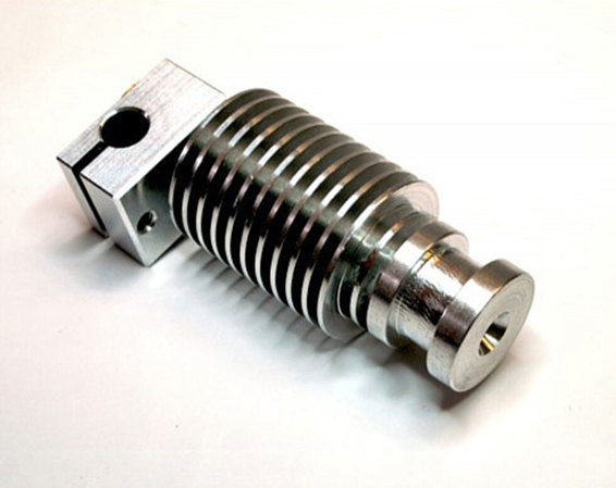
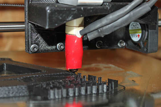
This E3D V5 is an all-metal hot end and requires active cooling from a fan.
But making a hot end completely out of metal presents some design challenges that are still being overcome. One of the biggest problems is that the heat from the heating block is transferred more efficiently across the entire hot end, meaning the mounting point can get too hot for the mount. To solve this problem, much larger heat sinks are needed, and a fan is often required. But the versatility of all-metal hot ends can definitely make the challenges worth the trouble.
The Nozzle
The nozzle is often considered to be part of the hot end, but it’s a replaceable part that I think deserves its own section. Hot ends almost always come with a compatible nozzle, but hot end manufacturers also generally sell additional nozzles in a variety of sizes.
Why would you want to purchase different-size nozzles? Because, as I’ve explained in Chapter 3, the size of the nozzle is one of the factors that determines layer height—the larger the nozzle, the more of an increase in layer height. Nozzle size isn’t the only thing that determines layer height, so there is some wiggle room for each nozzle size. But if you want to print a layer height that is significantly different, it can be worth changing nozzles.
Nozzles that come with hot ends are usually somewhere between .25mm and .50mm, because that’s a general size that is useful for most printing. But nozzles can be much smaller for specialized printing where very fine detail is required. Alternatively, some prints can be done with larger nozzles in order to print large objects more quickly.
![]()
WATCH OUT!
Nozzles aren’t generally compatible between different hot end models. This is because hot ends usually have nozzles that are made specifically for them. They use different threads, are different sizes, and are sometimes even different shapes. For this reason, it may be a good idea to check ahead of time what nozzles are available if you know you’re going to need a smaller- or larger-than-usual nozzle.
Print Fans
In addition to the hot end fans that are used to cool the hot end for mounting, one or more fans can also be used to cool the printed object itself. The fan is directed toward the extruded filament as it exits the nozzle in order to quickly cool the plastic.
The purpose of cooling the plastic is to get from the high temperature needed for extrusion to room temperature as quickly as possible. Plastic expands when it gets hot and contracts as it cools. That contraction can result in warped parts, because the entire part cools and contracts together. So a fan can be used to cool the filament quickly to avoid the entire part contracting at once, which helps to reduce warping.
Some filament materials, like PLA, also require active cooling from a fan to combat deformation. PLA is very soft until it cools, and the plastic can sag as its being printed if it’s not cool. This is especially apparent when printing overhangs or bridges, which will sag dramatically if the plastic is too hot.
Having a fan blowing on the plastic coming out of the nozzle allows you to print overhangs and bridges without them becoming deformed. Just a fan blowing in the direction of the nozzle can do a lot to help, but in order to cool effectively, fan shrouds can be used. The shroud acts as a sort of funnel to direct air to a very small area just below the nozzle where the filament is being deposited. This very quickly cools the filament as soon as it exits the nozzle, so the plastic gets hard and doesn’t deform.
Whether you should use a fan is determined by the material you’re using. For PLA, a print fan is virtually a necessity. For other materials, like ABS, a fan can actually be detrimental to print quality. ABS isn’t as soft as PLA when it’s extruded, so a fan isn’t needed to keep it from deforming. In fact, actively cooling ABS with a fan can make it solidify too much and can keep it from sticking to the previous layer.
If the 3D printer is equipped with a print fan, it’s usually controlled via software. The slicer software can turn the fan on and off (or even on at different speeds) throughout the printing process. It’s common to have the fan on at different parts of the print (like for overhangs) and off for others (like the first few layers). In later chapters, I’ll be going over when and how to use print fans, but for now, you should just be aware of its purpose.
Using Multiple Extruders
All FFF 3D printers have at least one extruder, but it’s also possible to have multiple extruders on the same printer. These are mounted right next to each other so the printer can use all of the extruders at the same time. The most basic reason for doing this is so you can print a single part in more than one color. But the possibilities introduced by using dual extruders (or more) can be much more exciting than just making colorful parts.
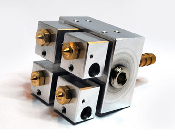
The Kraken, also made by E3D, has four extruders built into a single unit.
(Courtesy of E3D)
For Support Material
One very useful way to take advantage of a dual extruder setup is to use one extruder for regular filament and the other for support material. There are special kinds of filament which are formulated specifically for this task. Some manufacturers, such as Stratasys, have developed their own formulas for accomplishing this task, but in many cases patents keep these from being available on printers from other manufacturers. When it comes to the most common support material in consumer printing, people tend to use high-impact polystyrene (HIPS). HIPS is a type of plastic that dissolves in a common solvent called limonene. Limonene doesn’t affect PLA or ABS, so HIPS can be used for support material and then dissolved away, leaving the printed part untouched.
Using a soluble support material like this in the second extruder eliminates the hassle of having to manually remove support material made from the same material as the part. Not only is it a lot of work to remove support material, it can be difficult to do without damaging the part if there are fine details. In some cases, support material could be almost impossible to remove if, for instance, it’s supporting internal geometry that can’t be reached.
Dual extruders with a standard material and soluble support material completely solve this problem. You can just print the part with the two types of filament, and when the print is finished, you can soak it in a limonene solution. After a few hours, the support material is dissolved away and your finished part can be removed.
For Filaments with Different Properties
Another use for dual extruders is printing two kinds of filament with different properties at the same time. A single part could be printed with a hard ABS plastic and also a flexible filament, for example. You could print a plastic tool with a soft rubbery handle. Or a part could be made with flexible joints to allow movement.
With the wide range of filaments on the market today, there are a lot of possibilities for an imaginative person. You can take advantage of the different melting points, coefficients of friction, hardness, and flexibility of various filament types to create unique objects. This is an area of 3D printing that is just starting to be explored, and a lot of unconventional designs are possible.
![]()
HOT TIP
It doesn’t stop with just dual extruders either. You can already purchase a four-extruder assembly meant for consumer printers that lets you print four different filament types simultaneously. You could use this to print two different colors of ABS, a flexible filament, and HIPS support material all at the same time. Or you could use it for any other combination of filament materials that you think would be useful. Imagine the kinds of designs you could come up with!
The Least You Need to Know
· An FFF extruder consists of a cold end that feeds filament into the hot end.
· Direct feed cold ends feed more reliably, while the lower mass of Bowden cold ends can improve print quality.
· In order to heat up the hot end, two specific electronic components are needed: a thermistor and a heating element.
· Multiple extruders can add a great deal of versatility to the kinds of prints a 3D printer is capable of.
All materials on the site are licensed Creative Commons Attribution-Sharealike 3.0 Unported CC BY-SA 3.0 & GNU Free Documentation License (GFDL)
If you are the copyright holder of any material contained on our site and intend to remove it, please contact our site administrator for approval.
© 2016-2026 All site design rights belong to S.Y.A.