Making Simple Robots (2014)
Chapter 3. Unevolved Robots
There are minimal elegant solutions to building capable devices so long as they spend their energies on themselves and not their “masters.”
— Mark W. Tilden
How simple can a robot get and still be considered a robot? That’s a question many robot makers have taken as a challenge. Most people would agree that a doll or a puppet that only moves when pulled or pushed by a person is not a robot. But how about a remote control model rover, which adds a layer of electronics between the human and the object? Is something a robot if its sensor is a mechanical on-off switch rather than a logic gate in a computer program? Or if its seemingly smart response to the environment around it is really a random series of movements? At the beginning of the computer age, it seemed that robot brains would keep growing in processing power. Instead, the challenge today is to see how many different situations a robot can handle with the least number of possible responses to choose from.
The earliest precursors of today’s robots didn’t have computer brains or electronic sensors. In fact, they didn’t even run on electricity. Automata—mechanical robots powered by wind-up mechanisms, springs, and weights—go back as far back as ancient China.Leonardo da Vinci designed a mechanical soldier in 1464. Swiss watchmaker Pierre Jaquet-Droz built a writing automaton in the shape of a boy in the late 1700s that still works today. Using a system of interchangeable teeth on a wheel that controls gears inside, it can be programmed to write up to 40 characters. As it writes, its eyes follow the movement of the quill pen across the page, and its hand stops to dip its quill pen in an inkwell. The Franklin Institute in Philadelphia houses its own drawing boy with the largest “memory” of any automaton known. It is programmed to create four drawings and three poems, two in French and one in English. Built by another Swiss clockmaker, Henri Maillardet, around the same time as the Swiss machine, it was the inspiration for the automaton seen in the movie Hugo.
Today, animated figures or entire scenes that move with the turn of a crank are found on wind-powered lawn ornaments and as DIY paper models. You can buy spring-operated dolls that walk, hop, and even flip in the air at any novelty shop. Slightly more upscale, Brazilian artist Chico Bicalho has a line of metal and wire mini-insectoid robots (Figure 3-1) activated by springs that you wind up with a key or by pulling a string. They move due to the vibration of a spinning off-center weight.
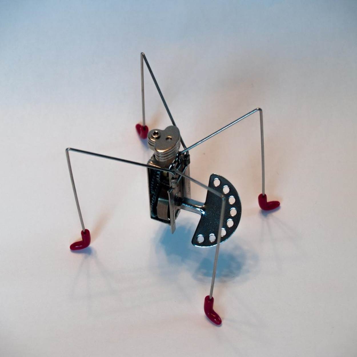
Figure 3-1. Chico Bicalho’s vibrating robots are powered by a wind-up spring.
Then there’s Dutch artist Theo Jansen’s Strandbeests, complicated pipe structures that use an ingenious series of joints (Figure 3-2). The original Strandbeests, built on a North Sea beach, were as large as elephants (hence the name, from the Dutch for “beach animal”). Made of PVC plumbing, they were propelled by wind, which they captured with sails and stored in a series of “stomachs” made of recycled plastic bottles. The latest generation of Strandbeests are tabletop-sized, feature windmill blades that can be powered with an electric fan, and can be reproduced—complete with fully assembled articulated joints—on a 3D printer.

Figure 3-2. A 3D-printed working model of Theo Jansen’s wind-powered Strandbeests that can be purchased on Shapeways.com. Credit: Tim van Bentum.
Modular robots are basically a set of parts that can assemble themselves in different ways to handle a variety of tasks. MIT researchers have developed box-shaped modular robots that move without any external actuators. Called M-Blocks, the cubes—about the size of a child’s alphabet blocks—fling themselves about with the help of a spinning weight inside. When the flywheel stops suddenly, the block keeps going, leaping into the air. Magnets along the edges help it grab onto nearby M-Blocks, allowing the robots to arrange themselves into the desired shape piece by piece. A toy called Cubelets is another form of modular robot (Figure 3-3). In this case, every Cubelet (similar in size to M-Blocks) performs a Sense, Think, or Action function. You “program” the Cubelet robot through your choice of modules. For example, if you combine a Brightness sense module with a Maximum think module and a Drive action module, you get a robot that measures the amount of light around, analyzes the data to see if it is over a certain threshold, and if it is, begins to move in that direction—in effect, a light-seeking robot.
|
|
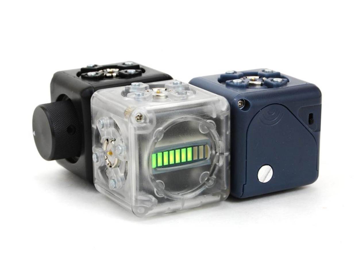
Figure 3-3. Cubelets are modular robotic blocks used as building toys. Credit: Modular Robotics.
Swarming robots are individuals that work in sync with each other. Inspired by social insects like termites, bees, and ants, swarming robots rely on group-think to accomplish their task. Harvard’s TERMES robots can build complex structures out of foam bricks with only four sensors, three actuators, and minimal brainpower to guide them. No bigger than a dinner plate and equipped with wheel-legs to help them climb, the TERMES robots perform a simple yes-no test on their immediate surroundings to decide whether the spot they’re at needs another brick or not
This programming lets them operate independently without having to follow a master plan and still create designs like towers, castles, and pyramids.
This chapter will show you how to build two electronic robots from the lower branches of the family tree: a Gliding Vibrobot and a Suped-Up Solar Wobblebot.
UNEVOLVED ROBOT LINKBOX
Franklin Institute Maillardet’s Automaton
Chico Bicalho’s wind-up vibrating robots
Theo Jansen’s Strandbeests
M-Blocks
Cubelets
TERMES
Project: Make a Swarm of Gliding Vibrobots
What Is a Vibrobot?
A vibrobot, or vibrating robot, is a primitive bot that moves due to the shaking of a rotating eccentric (off-center) weight, usually a vibrating motor.
|
|
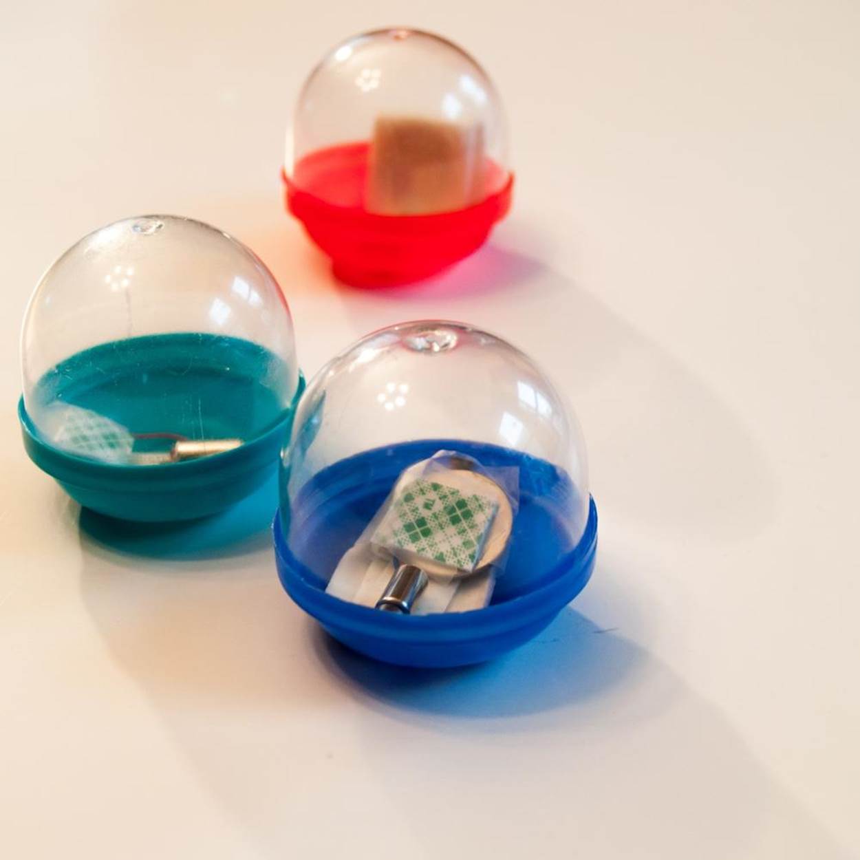
Figure 3-4. Three Vibrobots swarming.
What It Does
Vibrating robots behave in lifelike ways without any electronic control through a combination of random movements and mechanical programming due to their shape and distribution of weight.
Where It Came From
Probably the most famous example of a vibrating robot is the Bristlebot—the Throwie of the robot world. First appearing on the Evil Mad Scientist Laboratories website in 2007, the Bristlebot consists of the head snipped off a toothbrush, a tiny vibrating motor like those used in pagers and cell phones, and a disc battery. The bristles direct the bot in a roughly forward direction, with just enough unpredictability to give it character. Hexbug’s popular Nano robots are basically Bristlebots with added decorations and sometimes sensors. Another well-known vibrating robot design is usually known as the ArtBot. This has a larger DC motor to which a weight can be attached. The legs consist of felt-tip markers, so it draws as it moves. (You can find directions for a customizable Art-Making Vibrobot in my book Robotics: Discover the Science and Technology of the Future.)
However, not all vibrobots are “dumb.” Kilobots are tiny vibrating robots developed at Harvard. They can be programmed to move in preset patterns or to head towards or away from each other. About the size of quarter, each Kilobot consists of a circuit board, battery, two vibrating motors, and infrared sensors set upon three toothpick-like legs. Infrared signals (like the signals your remote sends to your TV when you push the buttons) tell the Kilobots what to do, and can program dozens or even hundreds of Kilobots simultaneously. The Kilobots can also send infrared signals to each other. Each Kilobot can be built from less than $50 worth of parts, and someday soon it may be possible to manufacture Kilobots in bulk for around $15 a piece, so assembling a Kilobot army won’t break the bank. In the meantime, you can buy a 10-pack of pre-assembled Kilobots for research or education purposes for around $1,000.
A swarming robot called I-Swarm was announced by a consortium of European scientists in 2009. Tinier than a pencil eraser, I-Swarm moved about on three tiny legs via sound vibrations and was steered by changing the frequency of the vibration, just like the Union College tensegrity robot in Chapter 2. They even hummed as they turned and glided around. Although the I-Swarm project never got beyond the prototype stage, even smaller microrobots could one day be used to deliver medicine or perform procedures inside the body.
How It Works
In 2013, Italian researcher Luca Giomi used custom-designed Bristlebots to show that collective behaviors like swarming can arise simply by letting self-propelled devices interact in a confined space. Working with a team at Harvard, Giomi developed two types ofBBots (as they were called)—walkers and spinners—by changing the angle of the bot’s bristly feet. The study found that when a crowd of each type of BBot reached its particular critical mass, the bots would start to move in sync, like a school of fish or flock of birds. The finding suggests that to some extent swarming behavior may be a result of the physical dimensions of a group as well as hardwired or voluntary decisions on the part of the individual swarm member. The study called this behavior the “mechanical intelligence” of swarms.
Making the Project
The Gliding Vibrobot is a Bristlebot reduced to its bare essence: just a vibrating motor, a disc battery, and a smooth round container to hold them. Although the Gliding Vibrobot doesn’t have feet that let you program it to move in a particular direction, its random wanderings still seem to result in that natural ability to swarm found in the research at Harvard. Build at least three and watch how they tend to form a pack if left long enough around a limited test area.
NOTE
Don’t forget to document your work!
Project Parameters
§ Time Needed: 1 hour
§ Cost: $10 or less
§ Difficulty: Easy
§ Safety Issues: None
What You Need to Know
§ Skills You Already Have: Basic craft skills
§ Skills You Will Learn: Observation, trial and error
Gather Your Materials
§ Three or more small vibrating motors (available from most electronics dealers, or recycle one from an old cell phone, pager, or Oral B Pulsar disposable electric toothbrush)
§ Three or more small coin cell batteries (1.5 to 3 volts)
§ Foam tape
§ Three or more 2-inch (5 cm) acorn-shaped plastic gumball machine capsules (the kind used to dispense toys)
§ Smooth test surface, such as a large piece of poster board and/or cardboard box top for a confined test area
Directions
Step 1: List Your Requirements
The goal of this project is to assemble a quick-and-easy Gliding Vibrobot that travels in large loops. As the number of little bots grows, so will the patterns you are likely to see. The more the merrier!
Step 2: Plan Your Project
Putting the pieces of this project together is easy. The challenge comes in positioning them just right, to achieve the kind of movement you want to see. While the plastic gumball machine capsule looks neat without adornment, you can add personality—and change the behavior of your bots—by adding craft decorations (see Step 7). Keep in mind that this project has no on/off switch. You should probably have a few extra batteries on hand, since you will burn through them as you test (and play with) your Vibrobots.
Step 3: Stop, Review, and Get Feedback
Check out the original Bristlebot how-to on the Evil Mad Scientist website for inspiration and building tips.
Step 4: Build Your Prototype
1. If you are repurposing an old vibrating motor, make sure each of its wires have a little metal exposed at the end. If not, strip off about 1/4 inch (3 mm) of insulation with a wire stripper (or carefully with a scissor or wire cutter).
2. Cut a piece of foam tape about 2 inches (5 cm) long. Stick the motor onto the tape, with the weight on the shaft hanging off the end so that it can spin freely.
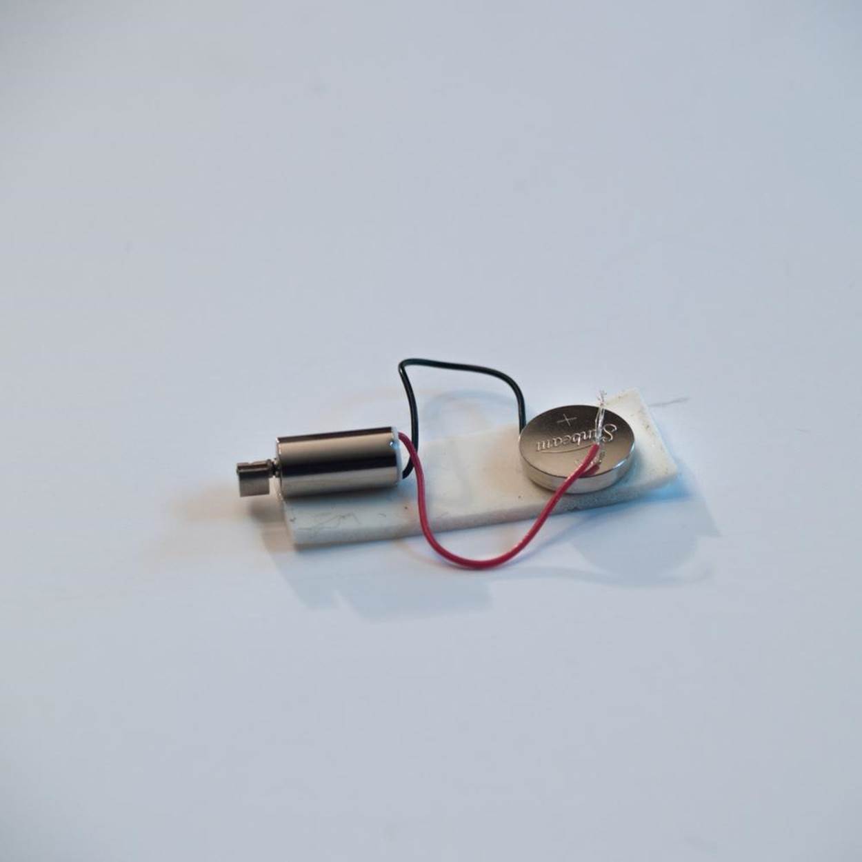
3. Press one wire down along the tape. If the wire is more than an inch (2.5 cm) long or so, curve it a bit so that the metal end is closer to the bottom of the motor. Then press the disk battery on top of the metal end of the wire to hold it in place. When you’re ready to turn your Vibrobot on, secure the other wire to the top of the battery with more tape.
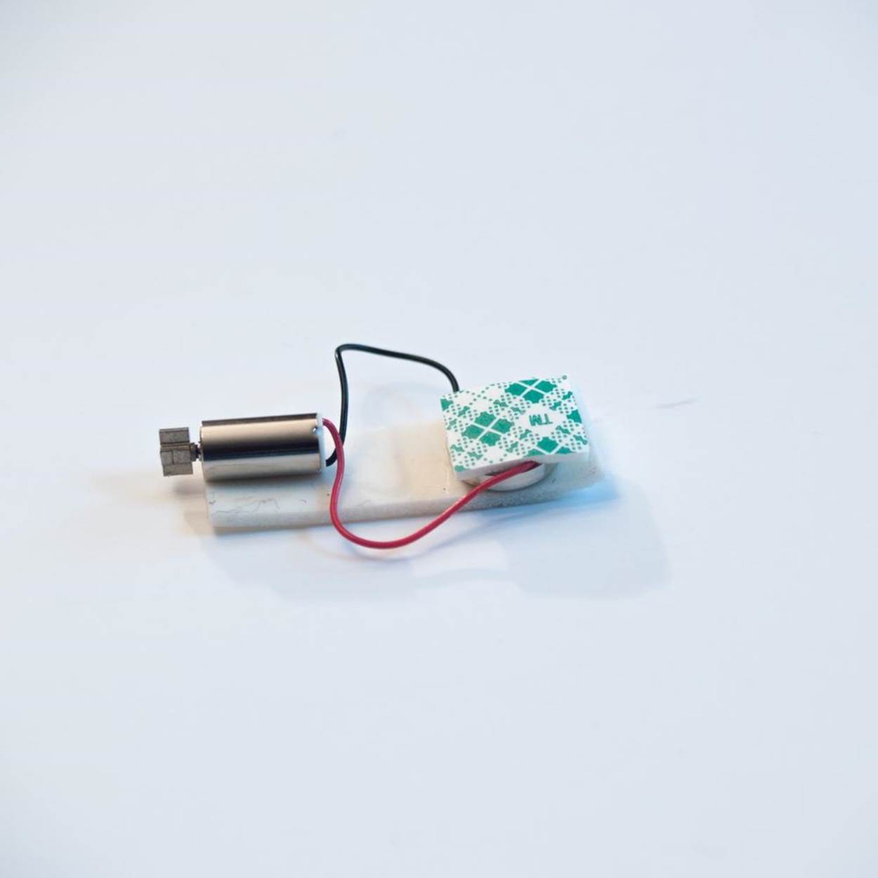
4. Take off the clear plastic lid on the gumball capsule and set it aside. Stick a square of foam tape inside the bottom (colored flat part) of the capsule, a little off-center. Attach the foam tape holding the motor and battery onto this piece of tape. You will have to fiddle with it a bit to get the Vibrobot to move forward and not spin in place. One configuration that works puts the battery up against the side (for ballast) and the weight on the motor shaft almost touching the side as well.

5. Make at least two more Gliding Vibrobots the same way.
6. Start each Vibrobot moving by attaching the top wire to the top of the battery with foam tape. Snap on the clear capsule lid and you’re ready to try ‘em out.

Step 5: Test Your Design
1. Give your Gliding Vibrobots a clear space to move around in (Figure 3-4). A big piece of poster board makes a nice smooth surface. You can make a test area with walls by putting some inside the lid of a copy paper box.
2. Turn them on, set them down, and watch how they move.
3. Adjust the position of the motors and the batteries as needed to get the kind of motion you’d like.
Step 6: Troubleshoot and Refine
Make sure the vibrating motor in your Vibrobot is firmly attached to the inside of the bot at all times. If your bot just sits and spins, try moving the parts around until it moves forward-ish.
Step 7: Adaptations and Extensions
This ultra-simple bot is just crying out for ornamentation. Stick on some googly eyes, ballpoint pen springs for antennae, or add minicraft stick “skis” to the bottom. You can even create flying saucer landing gear by sticking some long straight pins with plastic ball ends through the bottom of the plastic gumball capsule and hot gluing in place. For advanced makers, try adding some popular Bristlebot upgrades like two flat vibrating motors and a light-sensing circuit that tells the bot to turn towards or away from the light.
GLIDING VIBROBOT LINKBOX
Evil Mad Scientist Bristlebot tutorial
Kilobots (order at K-team)
Hexbug
Bristlebot swarm research
ScienceBuddies Steerable Bristlebot
Project: Make a Souped-Up Solar BEAM Wobblebot
What Is a BEAM Robot?
A BEAM robot is a primitive solar-powered bot that behaves in lifelike ways.
|
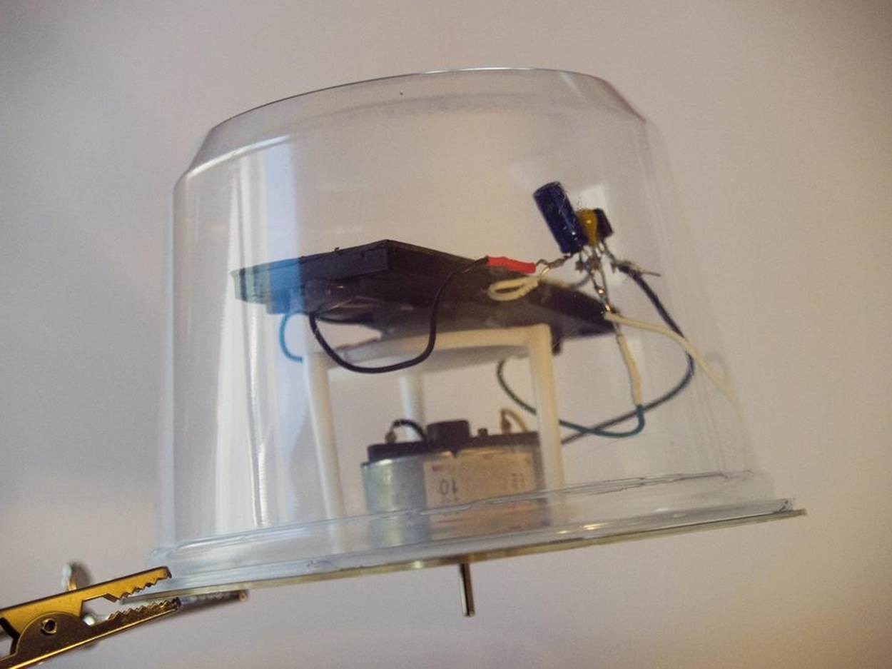
|
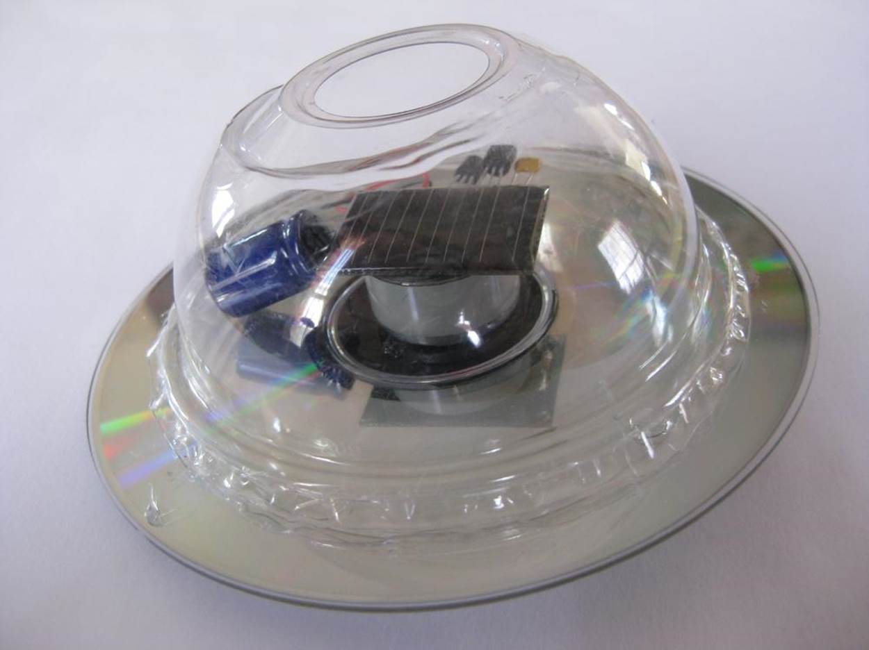
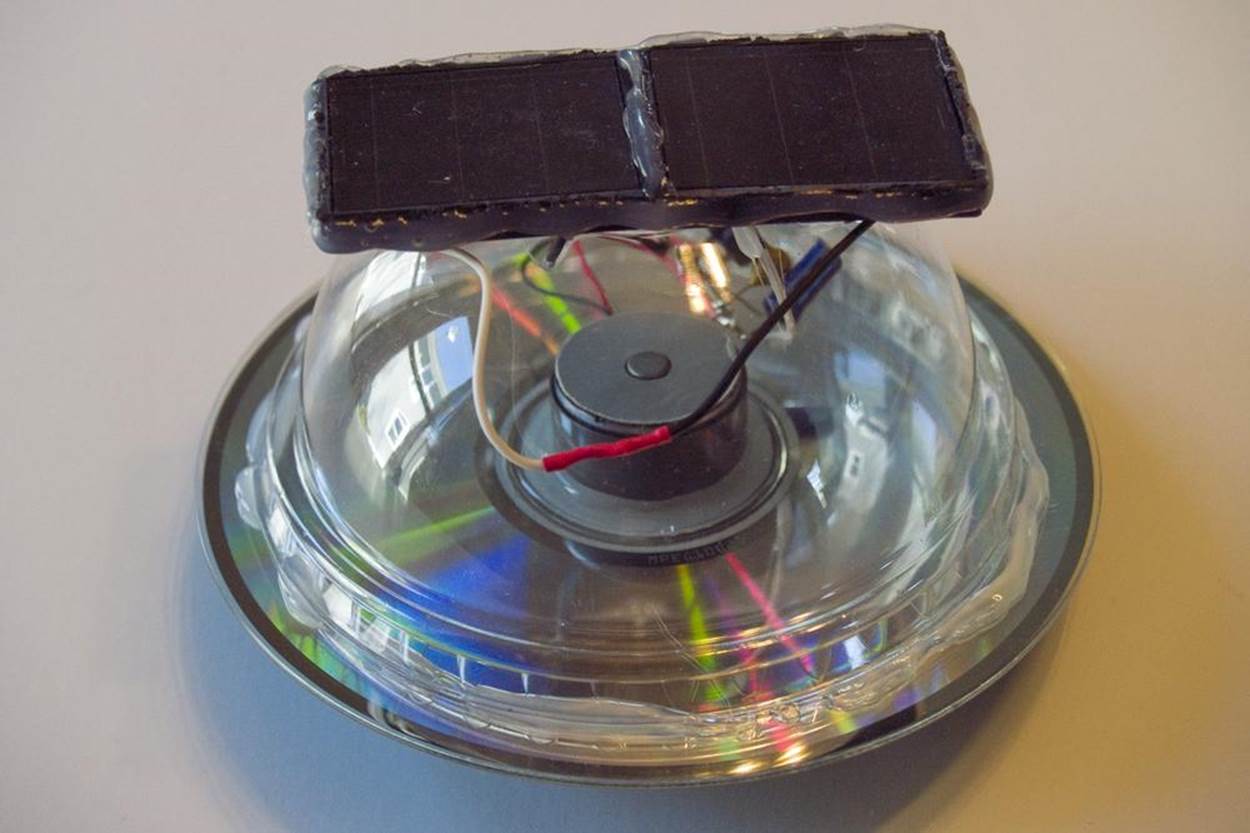
Figure 3-5. A finished wobblebot
What It Does
A BEAM robot is controlled by a primitive “nervous system” that uses components like switches and transistors instead of a computer “brain.”
Where It Came From
For hobbyists, the bare-bones robot craze really came into its own with the advent of BEAM Robotics. BEAM—which stands for Biology, Electronics, Aesthetics, and Mechanics—was formulated in 1991 by robotics physicist Mark W. Tilden. Tilden, who worked on both NASA rovers and the Wowwee Robosapien line of toy robots, broadened the definition of “robot” to include any machine that could interact with its environment, even if its behavior relied more on reflex than reasoning. In his book JunkBots, BugBots & Bots on Wheels (McGraw-Hill Osborne Media), Tilden and coauthor David Hrynkiw describe the concept of appropriate technology, the idea of using the most low-level components possible. Among other advantages, building things with primitive technology lets you use parts that are cheaper and easier to find. It’s also easier to diagnose problems, because there are fewer parts and they’re less complicated to test and fix.
The Biology in BEAM refers to the idea that nature provides many elegant models that can be used to solve robotic design problems. But it also suggests that robots, like living things, exist along a spectrum that ranges from primitive to complex. Like any primitive creature, the BEAM robots’ primary objective is to survive. Since BEAM robots are typically solar-powered, that means they can find their own food wherever there is light. For this reason, many BEAM robots have Electronic sensors to detect light and direct the robot towards it.
The Aesthetics and Mechanical aspects of BEAM come into play in the design. A well-designed BEAM robot is neat, tidy, and attractive. Everything fits together, so pieces are not apt to come flying off. Ideally, its design is also efficient. Just like programmable materials and smart bodies, the architecture of a BEAM robot should help it move the way its supposed to, and hinder it from doing things it shouldn’t. Good aesthetics also means it’s nicer to look at—which can help it draw the attention and admiration of other robot builders, who may be inspired to help the BEAM robot reproduce and evolve to the next level.
BEAM robots are mainly a hobbyist phenomena. They’re not generally found in laboratories or industry, although they heavily influenced the present-day trend towards simple robotic design. You’re most likely to see BEAM robots in the form of scratch-built designs using inexpensive or reclaimed components, or as kits. One well-known model is the light-chasing MouseBot, so-called because of its origins as an upcycled computer mouse. Another favorite is the elegant bump-and-turn BeetleBot designed by Jérôme Demers, which has two antennas connected to switches that act as touch sensors. BEAM was also the inspiration for the Hexbug line of miniature toy robots, many of which employ common BEAM elements.
How It Works
One classic type of BEAM power system is the Miller Solar Engine, designed by Andrew Miller around 1999. It consists of a storage capacitor—a component that works something like a rechargeable battery, except that it releases all its electricity in one burst—which is charged by the solar panels, and other components that determine when the electrical charge in the storage capacitor is released. Like the safety valve on an overflowing tub, when the charge in the storage capacitor reaches a certain level, a smaller capacitor will let electricity flow to a voltage trigger, which activates a transistor that sends power to the motor. When the storage capacitor is drained below the smaller capacitor’s threshold, it goes back to storage mode until it overflows again. As a result, BEAM bots run in short bursts, that can be lengthened or shortened according to what kind of capacitor is used.
Making The Project
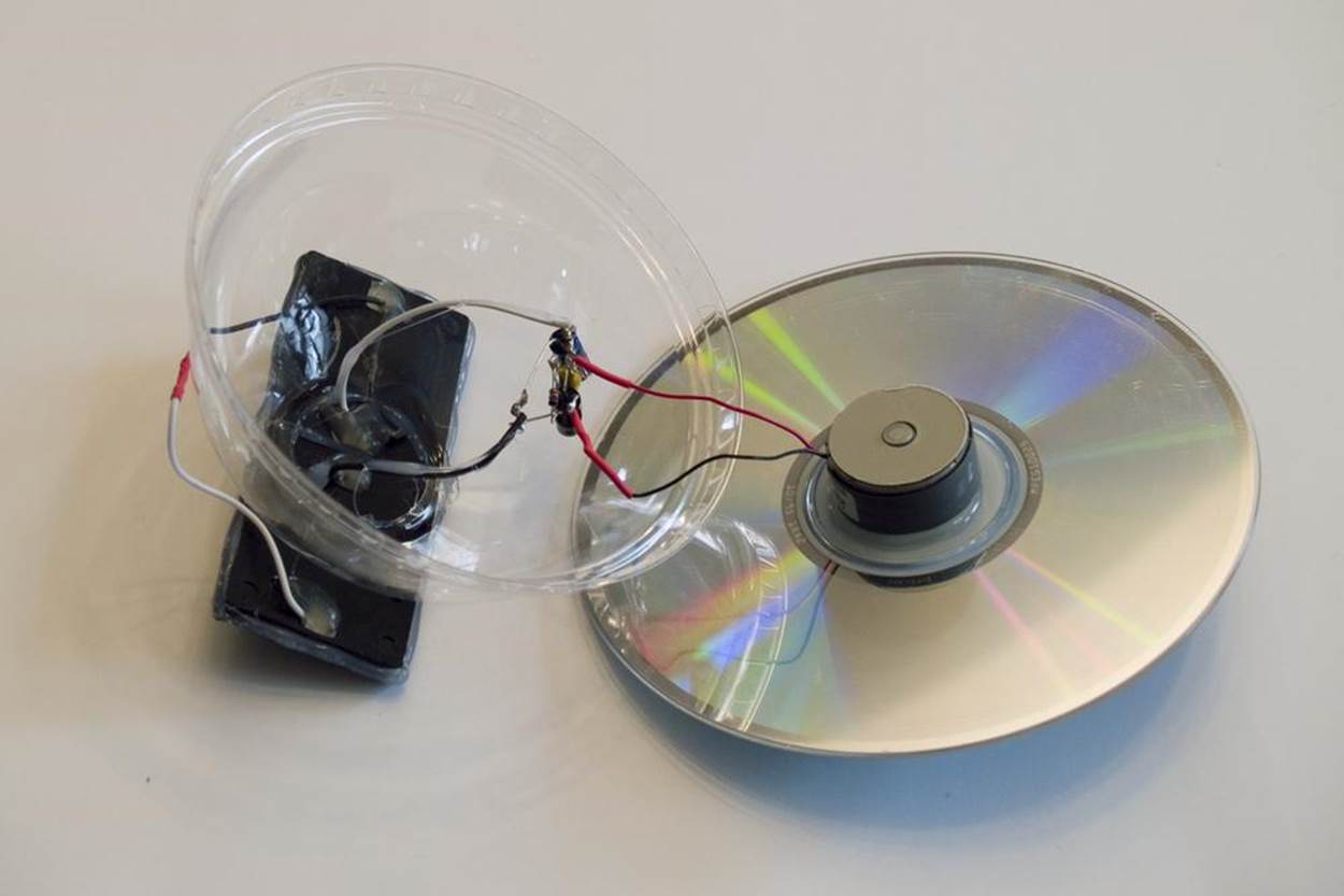
This project combines a Miller Solar Engine with the design of a Solar Wobblebot, a project from my book Robotics: Discover the Science and Technology of the Future. The original Solar Wobblebot (Figure 3-6) ran directly off the solar panel from a dollar store garden light—but only when there was enough light to power it. The Miller Solar Engine can also work in lower light levels by storing energy in a rechargeable capacitor and releasing it all at once. The stronger the light, the more frequent the bursts.
|
|
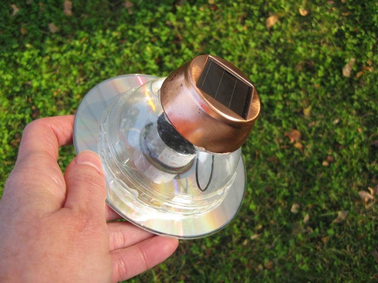
Figure 3-6. The original design for the Solar Wobblebot
NOTE
Don’t forget to document your work!
Project Parameters
§ Time Needed: 3–4 hours
§ Cost: $10–$30
§ Difficulty: Moderate
§ Safety Issues: Soldering tools and components touching them become extremely hot and should be handled carefully. Components must be connected with the correct polarity (positive to positive, negative to negative), or they may heat up and burst.
Gather Your Materials
Miller Solar Engine Components
You can order all the electronic parts you need for this project from Solarbotics.com or other retailers. There are two configurations to choose from—fast, short bursts or slower, long-running releases (Figure 3-7). I like both, but you may get the most immediate gratification from the fast/short burst variety. Solarbotics offers bundles that have all the components you need, including a solar panel with a circuit board on the back, which makes soldering a lot easier. The solar panels come in two sizes, 4.5 volts and 6.7 volts; either will work. The bundles available are the following:
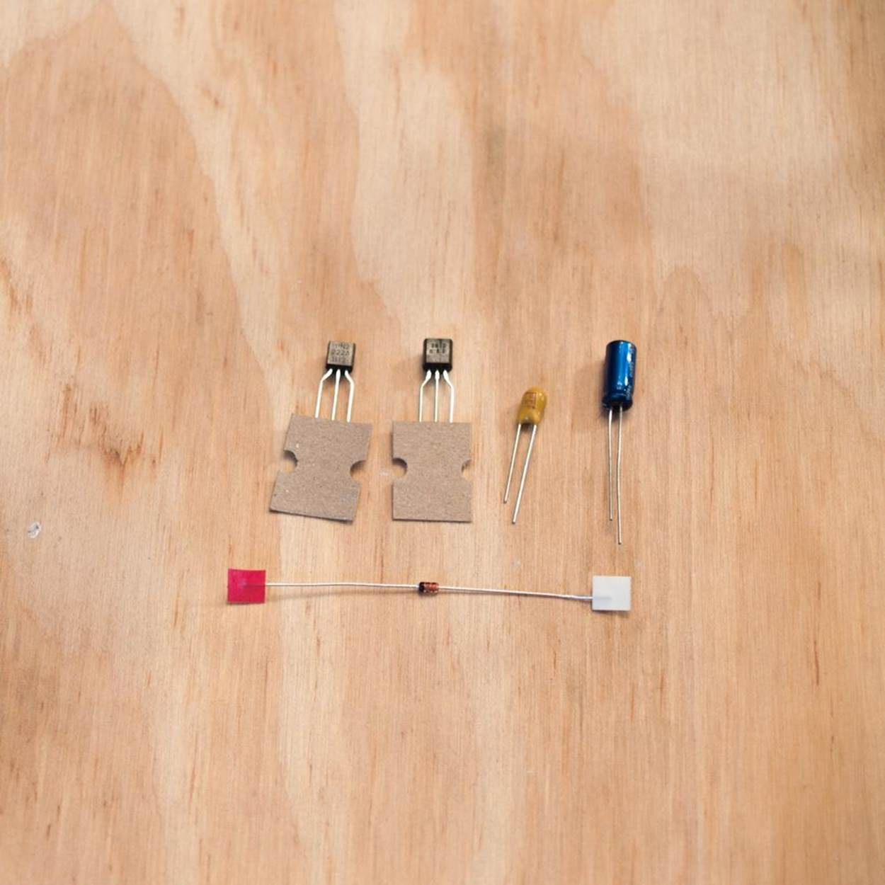
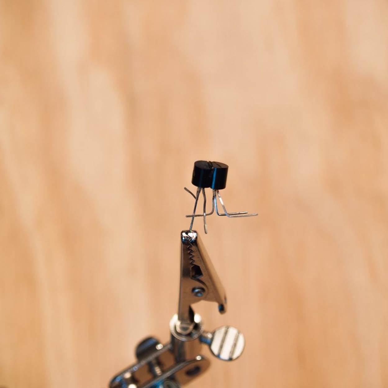
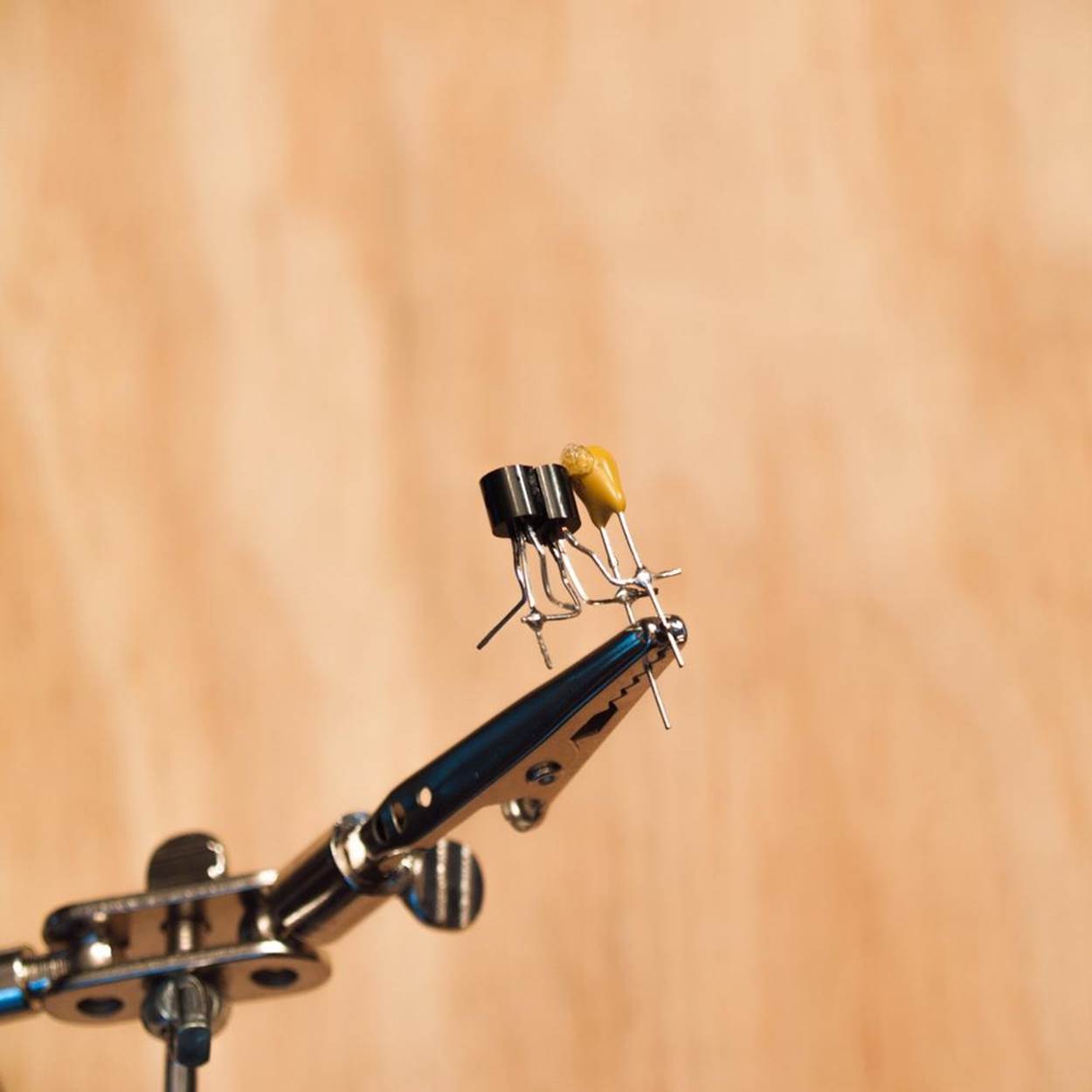
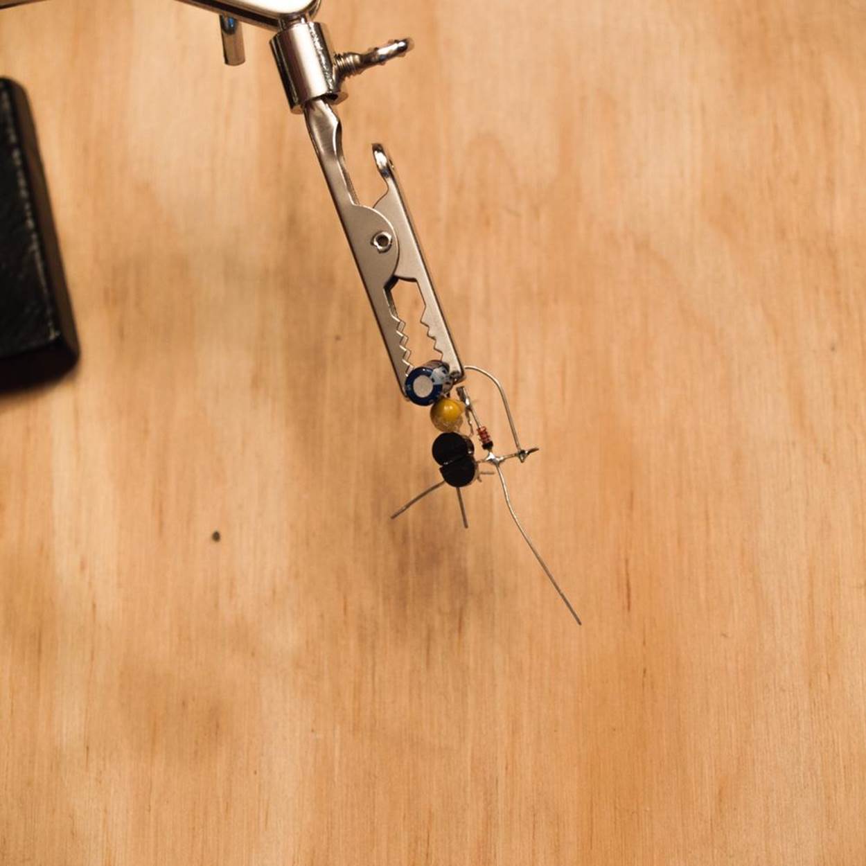
Figure 3-7. Components for long-running option. Top, L-R: PN2222 transistor, 1381 voltage trigger, disc capacitor, barrel capacitor. Bottom: diode.
§ SCC3733a-MSE Fast Bundle 1 (short bursts, 6.7V solar cell)
§ SCC2433b-MSE Fast Bundle 1 (short bursts, 4.5V solar cell)
§ SCC3733a-MSE Powerful Bundle 2 (long-running, 6.7V solar cell)
§ SCC2433b-MSE Powerful Bundle 2 (long-running, 4.5V solar cell)
Note that the motor that comes with the bundles above is narrow for Solar Wobblebot purposes, so you may need to jury-rig a holder from a piece of cardboard. You can also substitute one of the motors suggested further down, which have a wider body.
If you feel like a challenge, you can also “freeform” your components together without a board and use your own repurposed solar panels from cheap solar garden lights. The components listed below are the same as in the bundles above, but you can order them separately and just get what you need. That’s a good choice if you are making several bots and prefer to use your own solar cells and motors.
§ PN2222 NPN transistor (Solarbotics #TR2222)
WARNING
Transistors labeled PN2222 and 2N2222 are interchangeable; a third type, P2N2222, has the leads in reverse order, just to confuse us.
§ 1381 voltage trigger (Solarbotics #1381)
§ 1N914 silicon diode (Solarbotics # D1)
Long-running option
§ 6.8µF Tantalum (disc) capacitor (Solarbotics #CP6.8uF)
§ 0.35F 2.5V 5X11.5 mm (storage/barrel) capacitor (Solarbotics #CP0.35F)
Short-burst option
§ 1.0µF monolithic capacitor (Solarbotics #CP1.0uF)
§ 4700µF electrolytic capacitor (Solarbotics #CP4700uF)
Solar panels—you only need ONE of the following choices!
§ Solar cell/Miller Solar Engine circuit board (Solarbotics #SCC2433B-MSE)
§ Two dollar store solar garden lights
§ Solar cell rated at 4 volts or above
Motor—you only need ONE of the following choices!
Note: If your motor does not already have wires attached, you will have to solder some on.
§ Low-speed DC motor (Home Training Tools #EL-MOTOR2)
§ Mabuchi RF500TB DC motor (Solarbotics #RM4)
§ Low-voltage (1.5V or less), low-inertia DC motor (may be sold as “solar motor”)
§ Recycled low-voltage DC motor from old cassette tape, VCR, CD, or DVD player
Tools
§ Hot glue gun
§ Wire cutters and/or wire strippers
§ Glue dots
§ Solder and soldering tools (see Soldering Cheat Sheet)
§ Needle-nose pliers
§ Heat shrink tubing and heat gun (a crafter’s heat tool is fine) or electrical tape
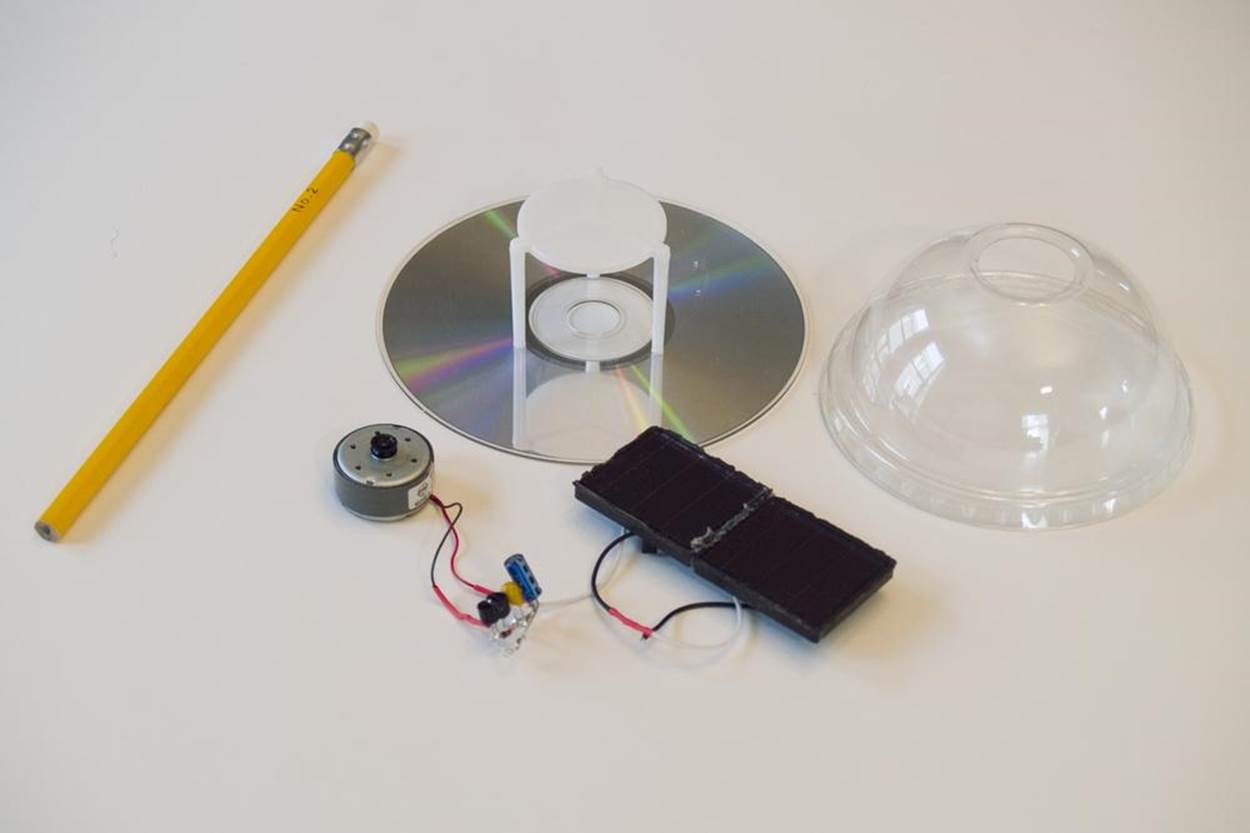
Solar Wobblebot body
§ Old CD or DVD disk
§ Clear plastic drink cup dome, or other food container (like that for small hummus dips or salad)
§ Pizza box spacer, fast food ketchup cup, or other platform for attaching the components to the body above the motor (if needed)
§ Eraser from a standard pencil (if desired)
What You Need to Know
Skills You Already Have
Following assembly directions, reading diagrams
Skills You Will Learn
Soldering, assembling electronics, making an electrical circuit
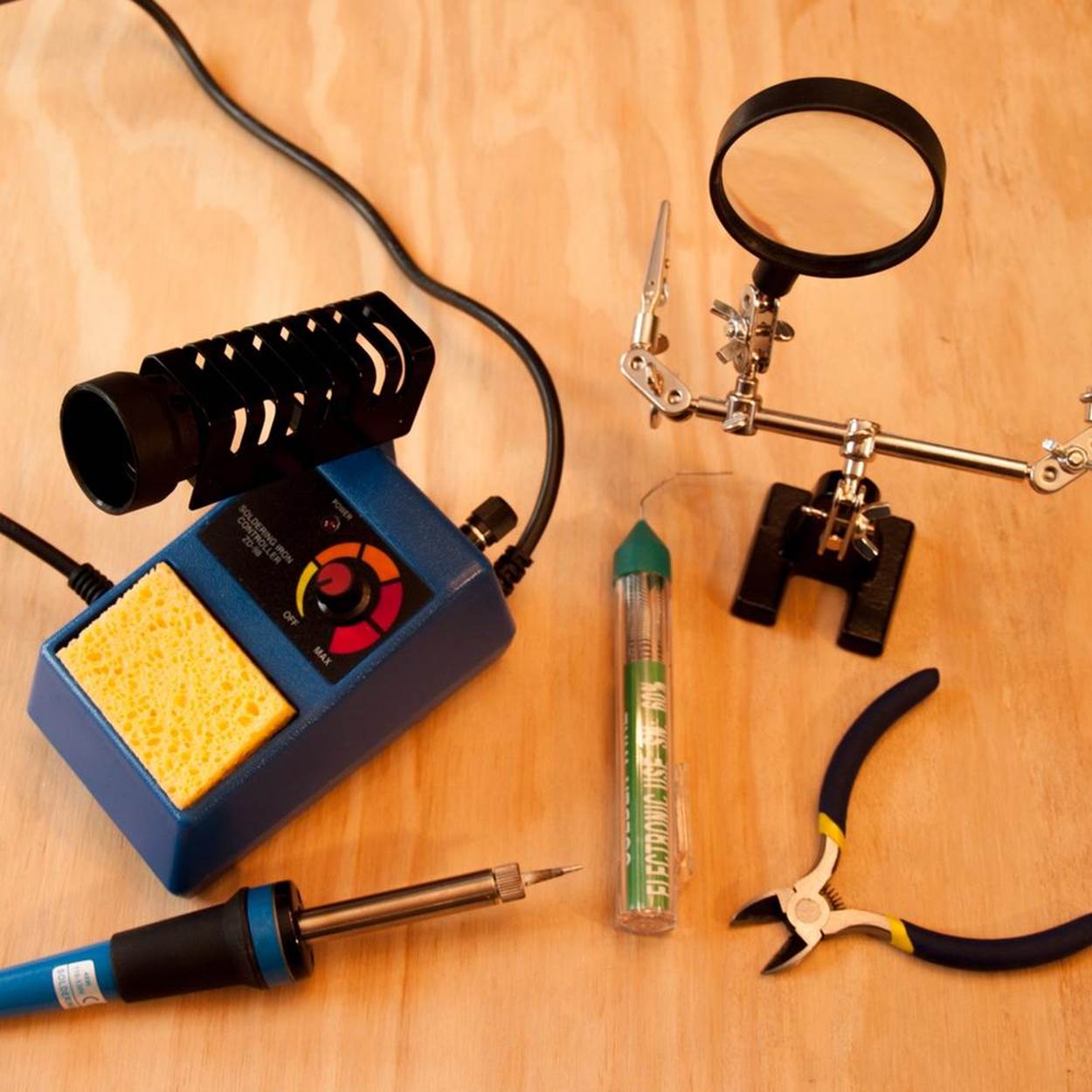
SOLDERING CHEAT SHEET
There’s a lot to know about soldering, and it takes a bit of practice to get good at it. That said, a beginner can do a good enough job for the projects in this book, even if what results isn’t pretty. Your goal in soldering is to make a secure bond between the parts you want to connect, without creating accidental bridges between the parts youdon’t want to connect—all while avoiding frying yourself, your furniture, or your components. Here’s what you need to know to get started.
Supplies
These are the bare-bones basics. See Soldering Linkbox (and related print resources) for more detailed advice about soldering tools and supplies. (I highly recommend the Make: Getting Started with Soldering Kit from Maker Shed. It comes with everything below except safety goggles, and includes a copy of Make’s Learn to Solderbook.) There are desoldering and other tools that you will need as you become more skilled and do more advanced soldering projects. The small tube of solder included in the kit is adequate for all the projects in this book, but you may want to get an additional roll of rosin-core solder (see below).
§ Soldering iron: A pencil-type soldering iron with a thin pointy tip will help you put the heat just where you want it. Inexpensive models come in 15, 25, and 30 watts. The lower the wattage, the longer it will take to heat up, but the less likely you are to fry any of your components.
§ Solder: For electronic components, a good general size to use is 0.025 inch (0.6 mm). The thinner the solder, the easier it is to melt. Be sure to use rosin-core solder. Rosin is a substance that melts onto and cleans the metal as you work, helping to create a good electrical connection. Many electronics veterans still prefer lead solder, because it has a lower melting point than lead-free varieties and is easier to work with. Lead-free solder has its own risks: it releases particulate-laden fumes when heated. However, if you’re working with children or will be handling the soldered parts once it’s done, then lead-free solder is your best bet. See below for solder safety tips.
§ Helping hand tool: This is a stand with bendable arms that have alligator clips on the ends. It can be incredibly handy (ahem!) when you need to keep your components steady while you’re working with the hot soldering tool. Some come with a magnifying glass to help you see what you’re doing. Some come combined with the soldering tool stand (see below), but if you’re tempted to buy one of those, check the reviews to make sure it doesn’t tip over if you try to swing the magnifying glass into a usable position. (I’m looking at you, RadioShack.)
§ Soldering tool stand: If you bought a beginner set with a little bent piece of metal to lean your hot iron against, consider getting a separate stand. Look for one that will hold even a narrow soldering tool up off the work surface. A place for a sponge is nice too (see next tip).
§ Damp sponge: The metal tip of the soldering iron reacts with the surrounding air whenever it gets hot, causing a layer of oxidized metal to form. So you’ll need to clean it while you’re soldering by wiping the hot tip across the sponge, often while you’re working. If your stand doesn’t have a sponge holder, make one out of an Altoids tin or metal jar lid. Cut a plain flat sponge to fit, then dampen it and place it in the holder. Keep it with your soldering supplies—you do not want to accidentally use the same sponge on your dishes.
§ Desoldering braid: This is a loosely woven strip of ribbon made of extremely thin copper wire. To remove excess solder from a joint, put a piece of braid over it and press it down with the hot soldering iron. The braid will wick away some of the melted solder from the joint. Lift it off the joint while it is still hot. Be careful not to touch the hot braid—hold it by the spool or use your pliers (below).
§ Safety goggles: Safety goggles will prevent flying bits of wire or solder from landing in your eye.
§ Needle-nose pliers: Here’s some truly quick-and-dirty advice for beginners who are having trouble making nice solder joints. If your wires are not quite soldered together the way you’d like, you can use your pliers to gently squish them together well enough to hold. You can then try to carefully add a little more solder—but be aware that as soon as you heat up the wire again, you run the risk of loosening up the existing solder. And when it’s easier to work with the components sitting right on the work surface, you can fit them into the open jaws of the pliers to hold them steady instead of clipping them onto a third hand tool.
Soldering Steps
1. Protect yourself. As mentioned above, solder contains lead and other nasty substances (even lead-free solder gives off toxic fumes), so use good ventilation. A small tabletop fan or Make’s DIY Mini Fume Extractor (see link below) can help, especially when you can’t open a window. If using lead solder, be aware that it’s most dangerous when ingested, so be sure to pick up and dispose of any leftover bits and wash your hands when you’re finished or before touching food. And take care with the hot soldering iron. Plug in the electric cord where no one will trip over it, and turn it off whenever you step away.
2. Make your work area safe. Do your soldering away from the family living space whenever possible—in the basement or garage is ideal. If that’s not an option, cover your workspace to make it easier to collect stray bits of solder and wire and be sure to work on a sturdy, heat-resistant surface. When I can’t get down to my local makerspace to solder, I throw an old vinyl tablecloth over my dining room table and set up my tools on a repurposed glass cutting board or slab of plywood.
3. Make sure the soldering iron is hot enough. Most low-cost soldering irons don’t have temperature controls—they’re either on or off. To be sure your soldering iron is hot enough, rub it on the damp sponge. It should cause the sponge to steam, and any solder it touches should melt within a second or two.
4. Tin your soldering iron’s tip. Once the soldering iron tip is clean of old solder, you can protect it by adding a new protective layer. This is called tinning the tip. Briefly touch the solder to the tip. Make sure to cover all around the tip. Wipe the tip gently across the damp sponge until it the new layer of solder is smooth and shiny. Repeat the tinning process as needed while you’re working.
5. To make a good joint, heat the thing(s) you want to solder. Solder flows towards heat. So heat up the wire, metal pad, or component you’re working with before adding the solder. To do this, hold the tip of the hot soldering iron to the place to be soldered for a second. Then push the solder under the tip until there is enough to cover the joint without blobbing over onto any nearby connections. Remove the solder but continue to hold the soldering iron to the joint for another second. This lets the solder flow smoothly around the joint. When soldering two wires together, the solder should form a little smooth mound around them. When soldering a wire through a hole in a circuit board, the solder should flow into the shape of a volcano, with the wire sticking out the top. After removing the soldering iron and letting the joint cool for a few seconds, try to wiggle the pieces around to make sure they are secure. If you need to add more solder, be very careful—once the soldering iron heats the existing solder, the joint may come apart again.
6. To move the solder from one spot to another, heat the new spot. If your solder overflows onto another joint, you create a solder bridge that can short your circuit. Move the excess back to its rightful place by applying heat to the spot where you want the excess to retreat to. Or use the desoldering braid to remove the excess altogether.
7. Be careful not to overheat components. Some components are touchy and will burn out if overheated. It’s also possible to melt a circuit board. Touch the soldering iron to your components as briefly as you can to make a good joint. And if you’ve got a piece of shrink tubing on the wire ready to slip over the finished joint, make sure it’s well back from the heat, or it may shrink before you’re ready. (If that happens, you may be able to stretch it open with a pin.)
BREAK THE CODE: MAGIC SMOKE
Overheat your components while soldering and you may see what veterans call “magic smoke” drift away. The caustic fumes, which smell like melting plastic and metal, are produced by overheating electronic circuits or components. Sadly, it usually means the life force of your component has gone on to join the great beyond. To prevent this while soldering, you can use a heat sink—a special spring-loaded clip or standard large-sized metal alligator clip that is placed between the joint to be soldered and the electronics. The metal clip will absorb the heat before it fries your circuit.
SOLDERING LINKBOX
Make: Skill Set: Soldering
Mini Fume Extractor
Carnegie Mellon Lead Soldering Safety Guidelines
U.S. Dept. of Energy Berkeley Lab Safe Soldering Work Practices
Soldering Is Easy (free printable comic book)
Adafruit Guide to Excellent Soldering
SparkFun: How to Solder
Learn to Solder by Brian Jepson, Tyler Moskowite, and Gregory Hayes (2012, O’Reilly Media)
The Makerspace Workbench by Adam Kemp (2013, Maker Media)
Make: Electronics by Charles Platt (2009, Maker Media)
Directions
Step 1: List Your Requirements
This project is about developing the soldering skills while building a BEAM Miller Solar Engine, and then attaching it to a body designed from recycled or repurposed materials.
Step 2: Plan Your Project
If you have never soldered it would be helpful to practice on a learning kit or by joining pieces of wire before tackling this project. As mentioned above, you can choose to use the Solarbotics solar panel with a printed circuit on the back, which will make it easier to attach the components. The freeform option is challenging but doable for a novice. Be prepared to spend more time, and work patiently to get everything right. Using a helping hand tool to hold the components in place while you solder will make things a lot less stressful.
The standard Solar Wobblebot also uses a “windshield” made from the clear plastic top of a soft drink cup, with a hole for the straw at the top. If your motor is small enough to fit through the hole, you can mount your solar panel(s) on the top, as in the original design. If not, the solar panel(s) can be attached to the inside of the Solar Wobblebot. In that case, you can use a large clear container (like a takeout food container) as a windshield to cover the entire assembly.
Step 3: Stop, Review, and Get Feedback
You can get more information and see some different variations of freeform Miller Solar Engines on the Solarbotics website and in the book JunkBots, BugBots & Bots on Wheels by BEAM creator Mark W. Tilden and Solarbotics chief David Hrynkiw (seeUnevolved Robot Linkbox).
Step 4: Build Your Prototype
Directions for Using the Solarbotics Circuit Board/Solar Panel:
NOTE
If you are not using the Solarbotics solar panel, skip ahead to the freeform instructions.
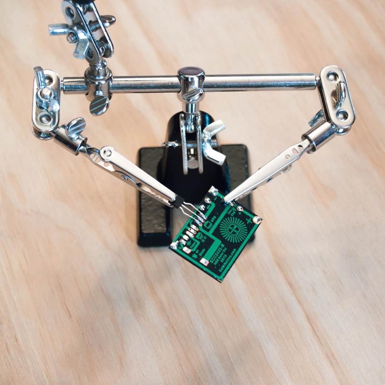
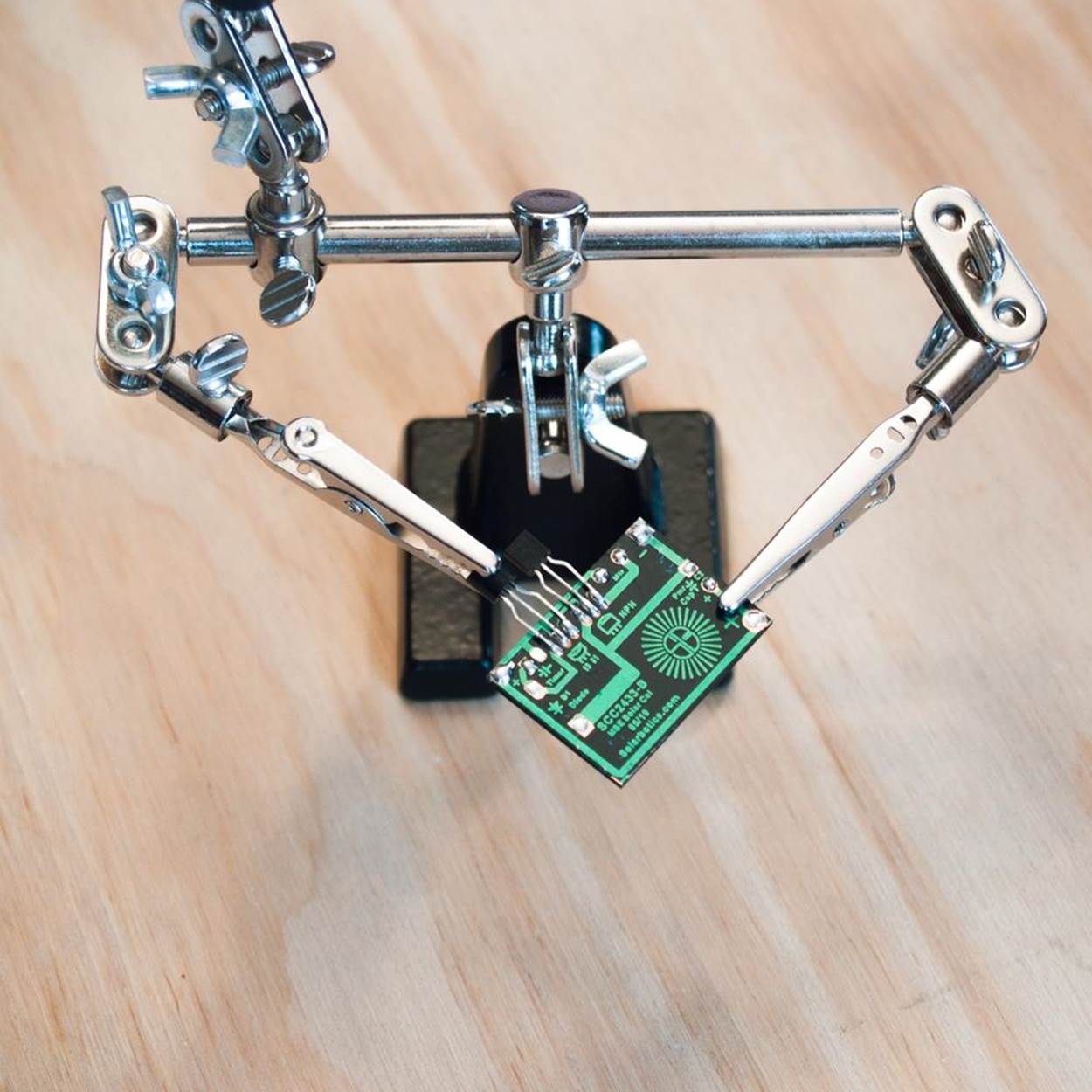
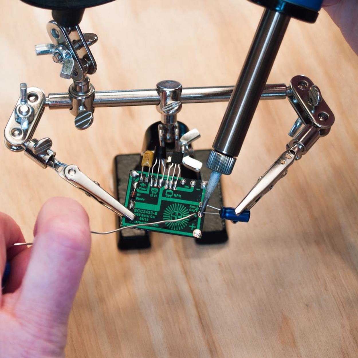
The directions below are adapted from the instructions that come with the Solarbotics solar panel with the circuit board on the back (Figure 3-8); I’ve made a few minor changes. (You can find a link to Solarbotics’ instructions in Unevolved Robot Linkbox.)
|
|
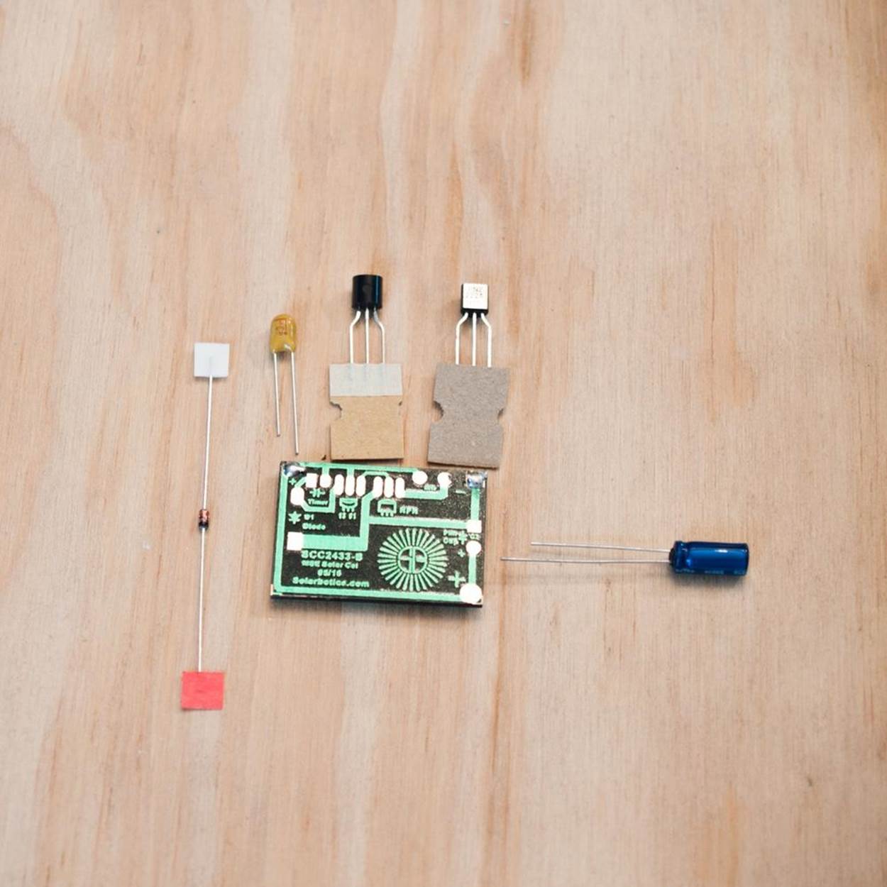
Figure 3-8. Solarbotics circuit board/solar panel and components for long-running Miller Solar Engine.
1. Before you attach each component, use the wire clippers to trim the legs so they fit on the board without hanging over too much. They should be about 3/8 of an inch long (1 cm).
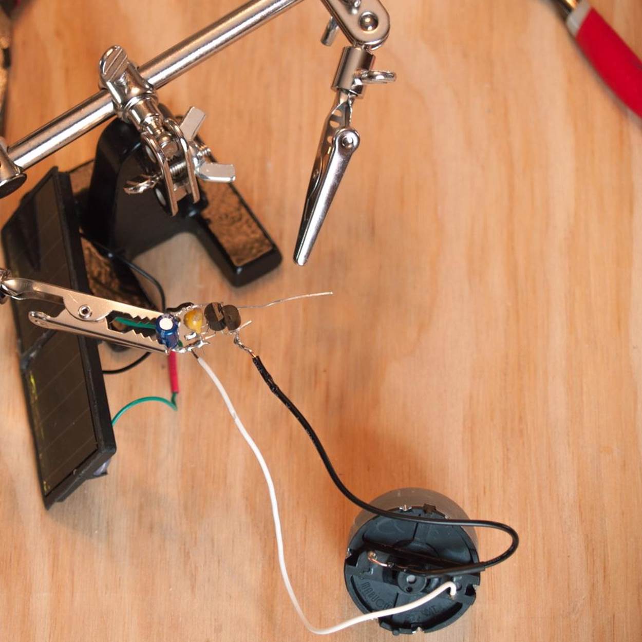
2. Hold the circuit board so the writing is right side up. For the following steps, as you attach each component, you will be going around the edge of the circuit board in a counterclockwise direction, starting at the middle of the top edge. It helps to apply a little solder before attaching the component to the board. You can either apply it directly to one lead (recommended by Make: editor Frank Teng), or to the metal pad on the circuit board (the Solarbotics method). The preapplied solder will help hold the component in place. Add a little more on top of the first leg as needed. Then feed solder to the second leg to attach it as well.
3. Take the PN2222 transistor and hold it flat side up. Solder the legs to the three oblong pads in the middle of the circuit board.
4. Take the 1381 voltage trigger and hold it rounded side up. Solder the legs to the three oblong pads to the left of the transistor.
5. Hold the disc capacitor so the positive side (marked with a +) is over the round pad to the left of the trigger and the negative side is over the square pad. Solder in place.

6. Take the diode and hold it so the end with the dark stripe is over the square pad on the left side of the circuit board, and the other end is over the round pad. Solder in place.
7. Take the barrel capacitor and hold it so the leg on the side with the dashed negative signs is over the square pad on the right side of the circuit board and the positive leg is over the round pad. Solder in place.
8. Take the leads from the motor. For extra stability, you can attach them to the circuit board “backwards”—so that the exposed metal tip of the wire is even with the edge of the circuit board and the insulated part goes back across the circuit board. Solder the motor leads onto the large round and hexagon-shaped pads on the right of the top edge. It doesn’t matter which lead goes to which pad.
That’s it! You’re ready to skip ahead to Step 5, testing the solar engine and assembling the Wobblebot body.
FREEFORM MILLER SOLAR ENGINE
NOTE
If you are using the Solarbotics solar panel circuit board, you can skip this section.
You will be using glue dots and solder to create a conga line of components that are connected to each other, starting with the PN2222 transistor.
For purposes of keeping left and right clear, consider all instructions to be from the point of view of holding them so the rounded back of the PN2222 transistor is towards you. When you need to bend a leg on a component, do it (gently) not more than 1/4 inch (6 mm) down from where it comes out of the plastic casing. All bends should be right angles unless otherwise noted.
1. Take the PN2222 transistor and gently bend the outer legs out to the sides.
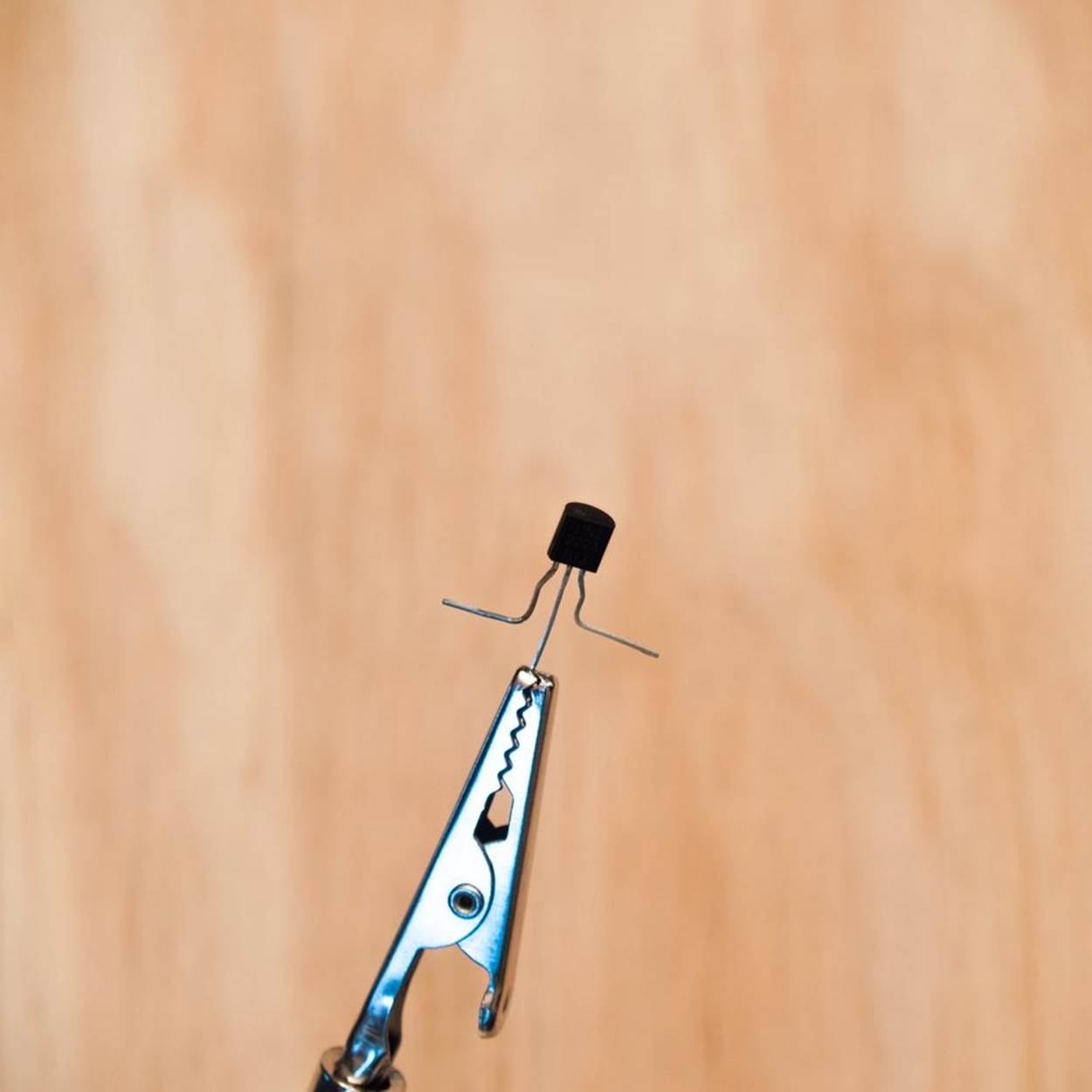
2. Take the 1381 voltage trigger and hold it so the flat part is facing towards you. Bend the middle and right leg back, away from you. Then bend the left leg towards you.
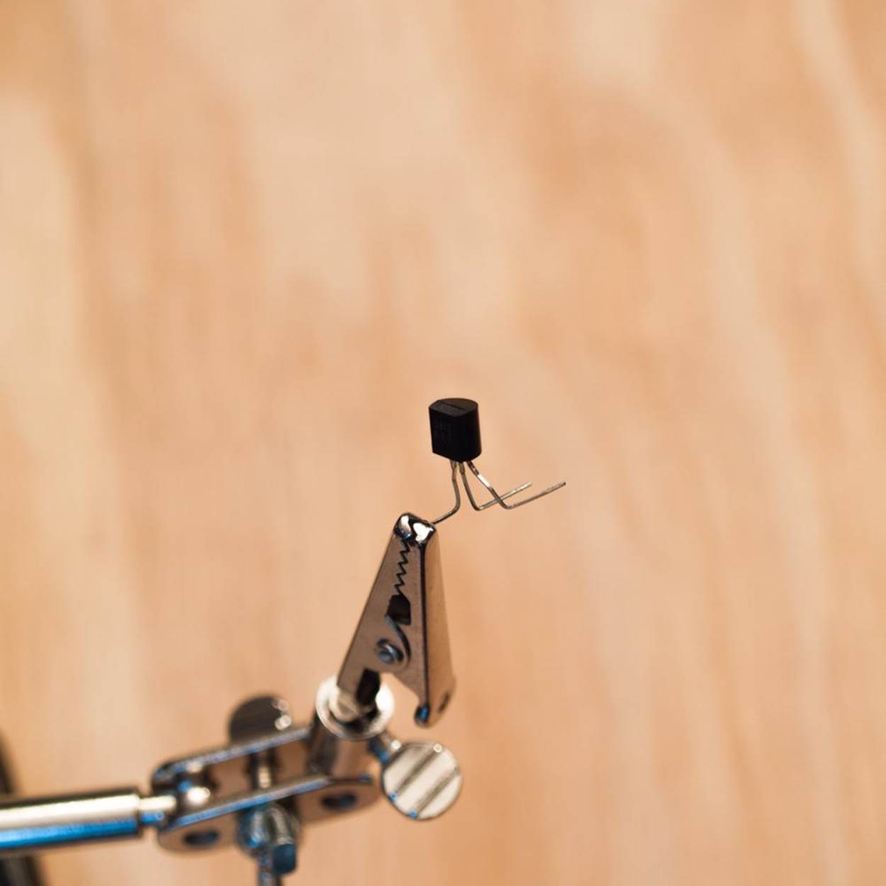
3. Use a glue dot to attach the flat side of the transistor to the flat side of the trigger. (You may want to mark the trigger with a white touch-up pen or bit of colored nail polish so you can tell them apart.) The left leg of the voltage trigger—which is pointing towards you at a right angle—should be touching the middle leg on the transistor. Solder those two legs together where they meet.
4. Use a glue dot to attach the disc capacitor to the back of the trigger, with the capacitor’s legs on the outside of the bent legs of the transistor. The little positive sign on the yellow capacitor should be facing out. Solder the left leg of the capacitor to the middle leg of the transistor. Then solder the right legs together where they meet.
5. Take the diode and lay it along the right side of the three components, so it is touching (or resting on the bend of) the outermost legs on that side. Make sure the black-striped end is facing towards the transistor (and you). Solder the diode leg at the black-striped end to the transistor leg where they meet. Solder the other leg to the trigger and the capacitor. (They are all connected.) Clip the excess wire at the end nearest the capacitor.
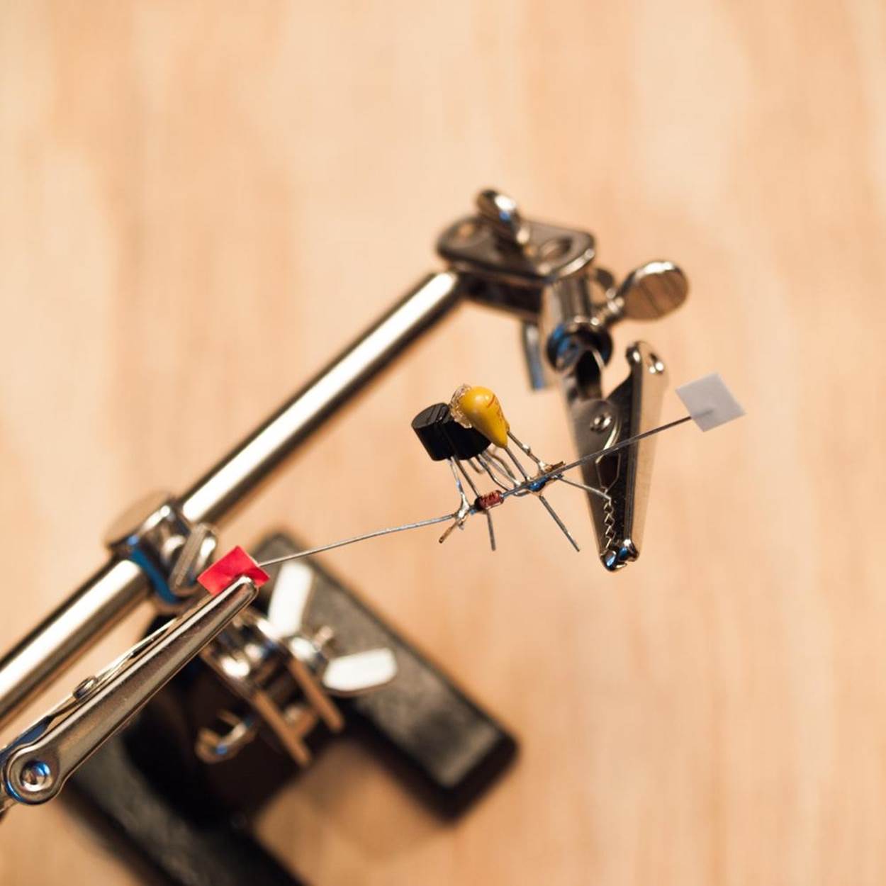
6. Take the barrel capacitor and hold it so that the negative side (with the negative signs running up the side like a dashed line) is on the right side as you’re looking at it. Bend the right leg of the barrel capacitor out to the side and then forward, towards you.
7. You can round off those bends a little, but leave some clearance so that leg doesn’t touch the conga line when it is attached. Use a glue dot to connect the barrel capacitor to the disc capacitor. It should be positioned so that the left (positive) leg of the barrel capacitor is touching the middle leg of the trigger (which is already soldered to the left leg of the disk capacitor). Solder them together where they meet.
8. Position the right (negative) leg of the barrel capacitor so it touches the right leg of the transistor. Solder them together where they meet.
THE SOLAR PANELS
NOTE
Follow these directions if you’re making the freeform version. If not, skip to Step 5.
1. If you are using solar panels from solar garden lights, you need to connect two together to generate enough voltage for your Miller Solar Engine.
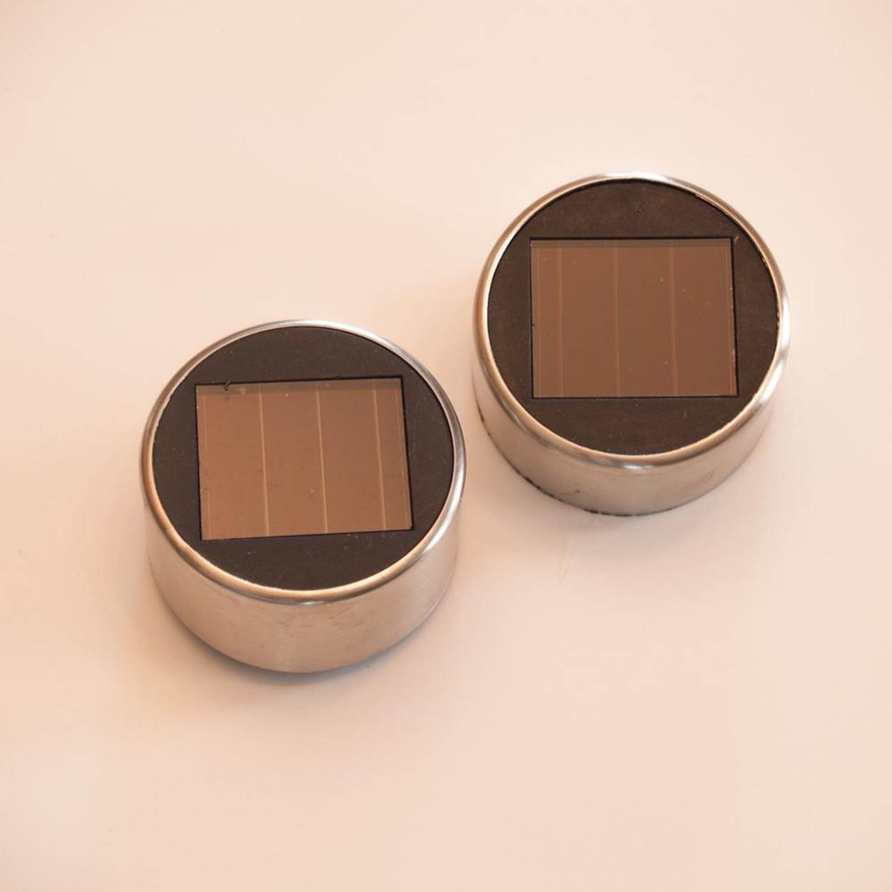
2. Open the solar garden lights and take out the battery.
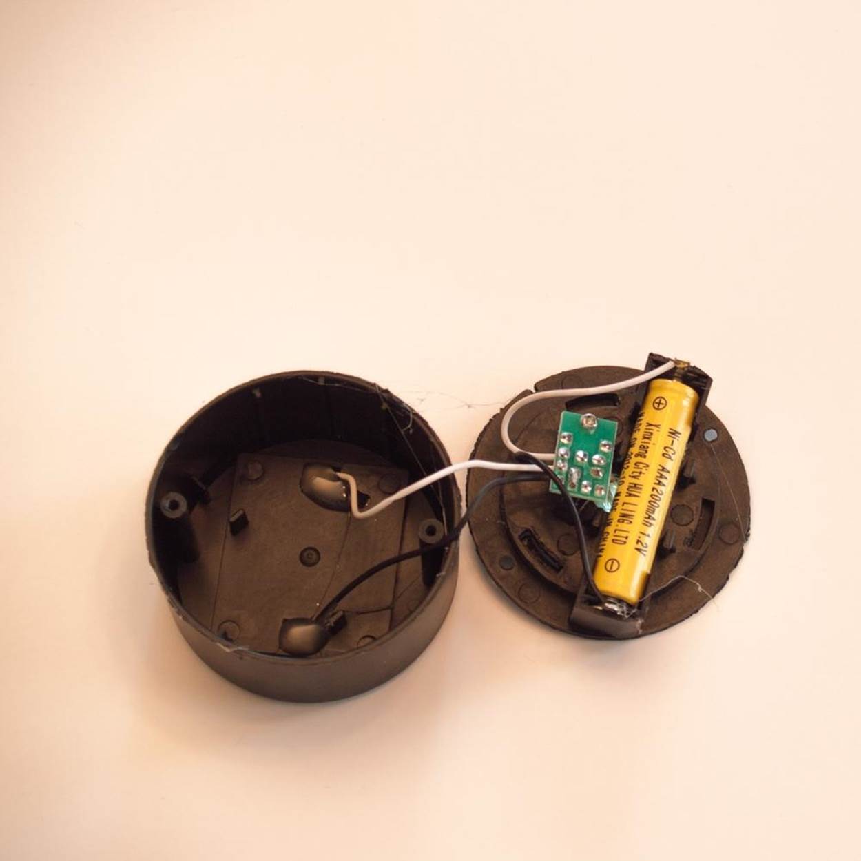
3. Cut the wires going to the solar cell as far from the cell as possible.
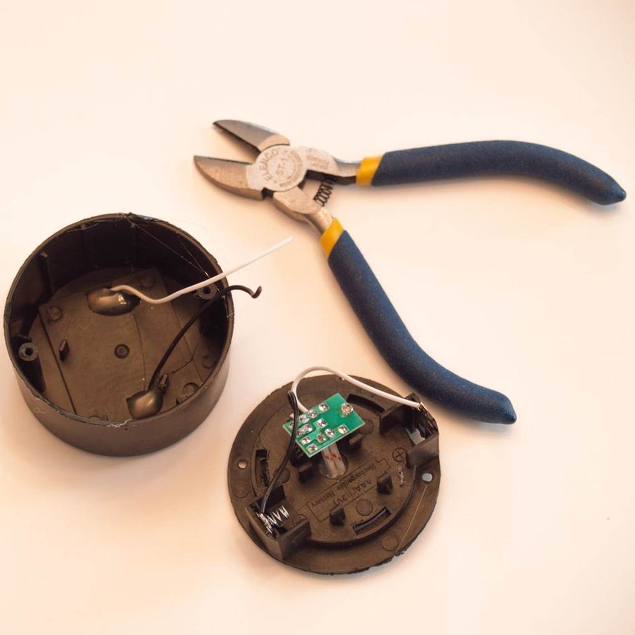
4. Remove the solar cells if you can do so without damaging the wires. If not, use the wire cutter or other short clippers to trim the soft plastic around them, leaving a frame to hold the panel and the wires.
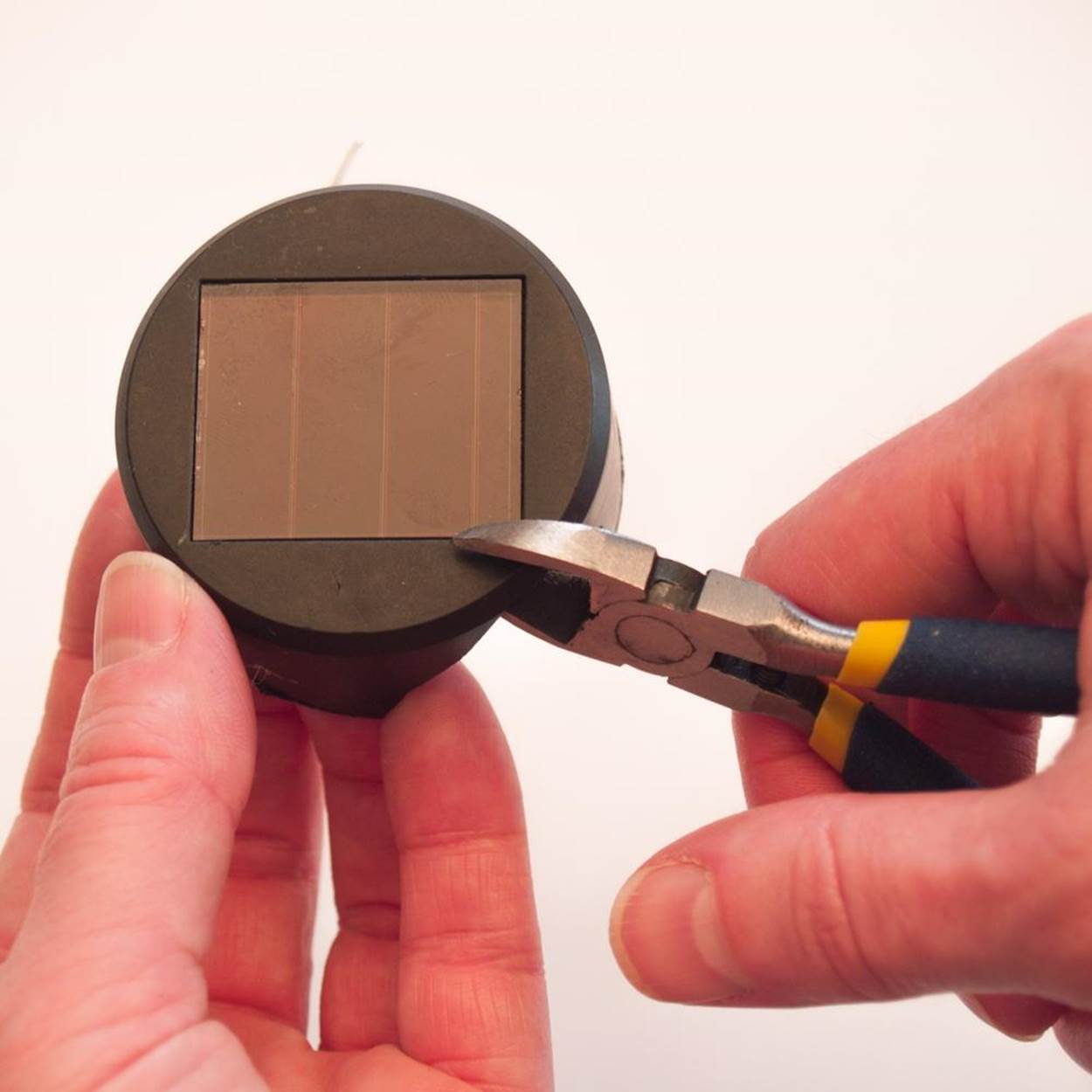
5. Then strip about 1/4 inch (6 mm) of insulation from the ends of the wires. The colors of the wires should indicate which is positive and which is negative (negative is usually black).
6. Hot glue your two solar cells together so that the positive wire from one is next to the negative wire from the other.
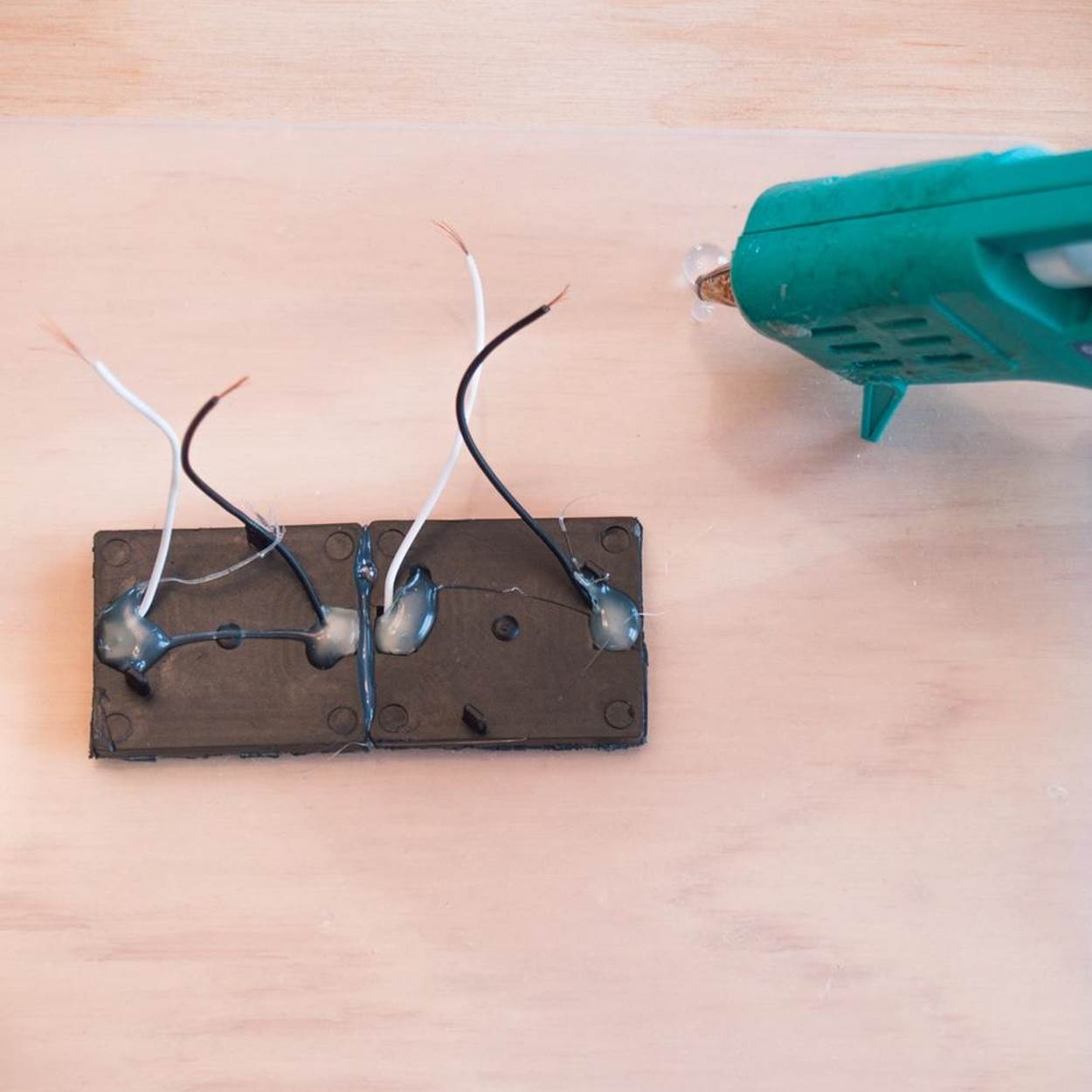
7. If using heat shrink tubing, cut a short piece wide enough to just fit a little loosely on the wire. Slip it over one of the wires on the outside edges of your joined solar cells and slide it down as far as it will go. Then—with the ends of the wires facing towards each other—twist the metal ends of the two outer wires (positive from one panel, negative from the other) together. Solder them together, being careful to keep the soldered joint narrow enough for the heat shrink tubing to fit over it. Slide the tubing over the joint. Use a heat gun (a crafting tool that’s like a superhot hair dryer) to shrink the tubing until it fits snugly over the joint.
Alternately, wrap the joint tightly with a little electrical tape.
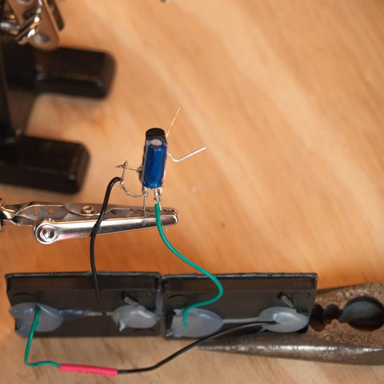
8. Take the remaining negative wire on your solar panels and twist it around the bent-out right leg of the barrel capacitor. Solder it on carefully. Take the positive wire from the solar panel and solder it to the positive leg of the barrel capacitor, leaving a little room for one more wire to be attached there.
THE MOTOR
Follow these directions if you are making the freeform version. Otherwise, skip to Step 5.
1. If you are using a recycled motor, you may want to test that it works with the solar engine before soldering it on. Try twisting the wires on or using alligator clips.
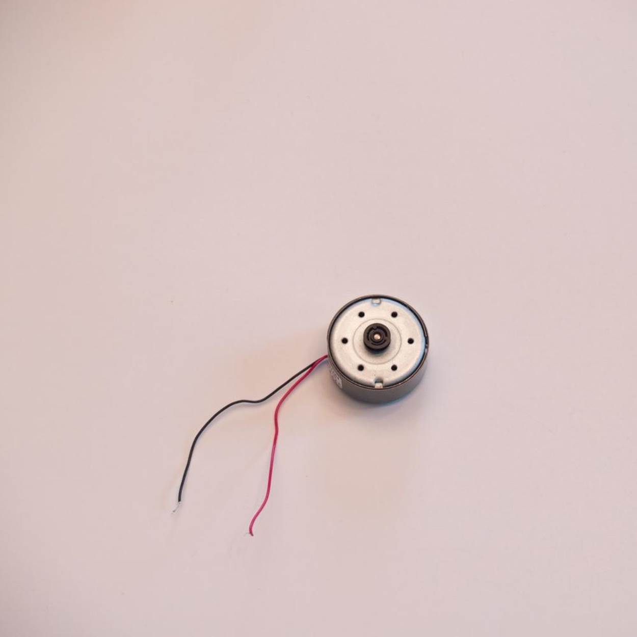
2. If using heat shrink tubing, cut two short pieces and slide them onto the motor wires, as far down as they will go.
3. The motor does have positive and negative leads, but it will work either way around. It will just spin in opposite directions, depending on how it is connected. Twist one of the motor wires onto the positive (left) side of the barrel capacitor. This is where you just attached the positive wire from the solar panel. Solder the motor wire on as well.
4. Solder the remaining motor wire to the left leg of the transistor. Slide the heat shrink tubing up to cover the solder joints and shrink to fit with the heat gun.
Step 5: Test Your Design
Before you attach it to the Solar Wobblebot body, test your Miller Solar Engine circuit.
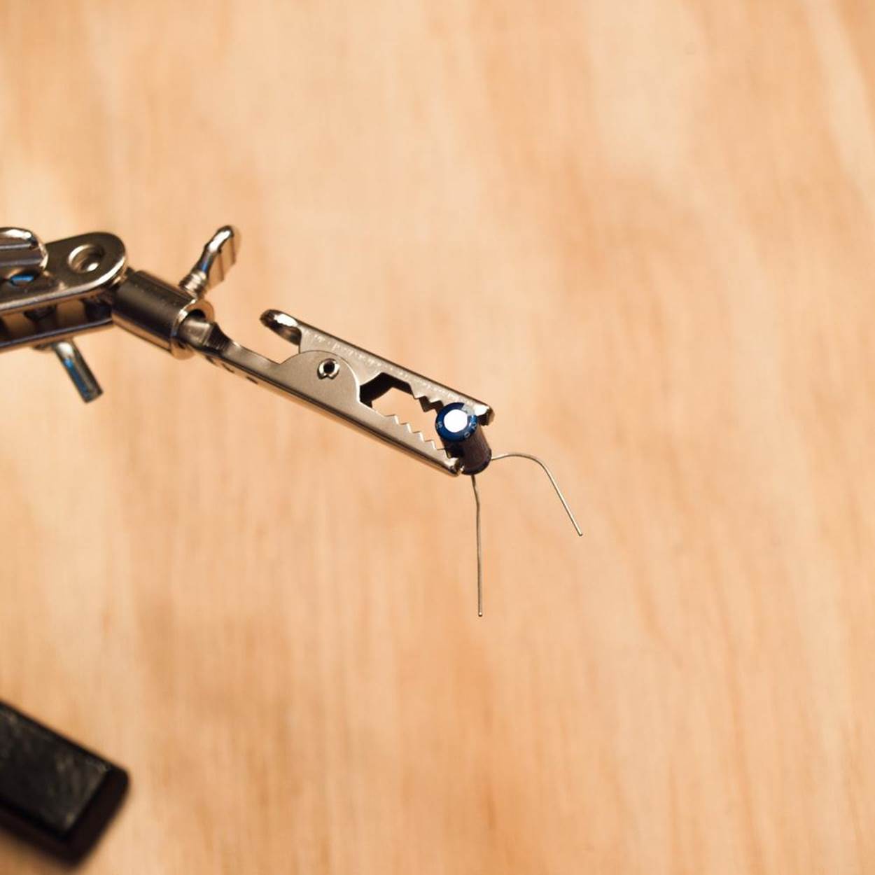
1. You may want to make a little shoe for the shaft of your motor, especially if it’s short. Remove the eraser from a standard pencil, squeezing the metal sleeve holding it on with your pliers to loosen it if needed. Push the shaft of the motor into the end of the eraser. Be sure to leave enough clearance to allow the shaft to spin. If you decided to skip the shoe, put a small piece of masking tape on the end of the motor to test it.
|
|
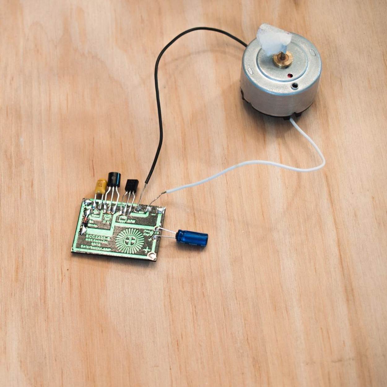
2. Before you test the solar panel, check to see if there is a protective sheet of clear plastic covering it, and if so, remove it. Expose the solar panel to bright sun or artificial light. In a minute or two, you should see the motor spin for several seconds. If it doesn’t, check the Troubleshooting tips in Step 6 before going any further.
The Solar Wobblebot body is quick and easy to assemble.
To make sure everything fits, you may want to prototype it with glue dots. That lets you move things around as needed before you attach the pieces permanently with hot glue.
|
|
1. If you are using a cup dome with an opening in the top and your motor fits through the hole, gently push it through so that the solar panels are on the outside. Be careful not to tear the wires. Attach the solar panels over the opening.
2. Attach the motor to the CD with the shaft sticking down through the hole.
|
|
3. If the solar panels are going inside the Solar Wobblebot body, mount them on a pizza box spacer, upside-down ketchup cup, or other platform that is attached above the motor. Be careful with the components and wires as you position them.
4. Attach the windshield to the CD, fitting it carefully over the motor and other components. Put your pieces in the brightest area you can find to see if your Suped-Up Solar Wobblebot will spin and move. If everything works, go ahead and attach permanently with hot glue.
|
|
Step 6: Troubleshoot and Refine
If your Suped-Up Solar Wobblebot isn’t running, check for broken wires, broken soldering connections, or shorts (where two metal pieces that shouldn’t be touching are touching). Also make sure the shaft of the motor can spin freely.
If you are using a recycled motor and did not check to make sure it works with the solar engine, that may be your problem. Some small motors that run fine off of a battery will not work with a solar panel. You must have a low inertia motor that doesn’t take a lot of current to get started. It’s also possible that your motor doesn’t have enough torque (circular force) to move the weight of the Wobblebot. In that case, you can try to convert it into a “flag-spinning” BEAM bot (see Step 7).
Step 7: Adaptations and Extensions
Once you’ve got your Miller Solar Engine working, you can make an ultra simple bot by simply turning whatever motor you use facing up. Instead of moving around, it can spin a small flag, sign, or colorful streamers attached to the shaft with a cocktail straw.
For more advanced DIY BEAM body designs, check the Instructables website and makezine.com, or try one of the Make: kits from Solarbotics or MakerShed.
UNEVOLVED ROBOT LINKBOX
Junkbots, Bugbots, and Bots on Wheels companion website
Original Bristlebot how-to
Solarbotics retail site
Miller Solar Engine kit documentation
Home Training Tools DC motor
Absolute Beginner’s Guide to Building Robots by (former Make: editorial director) Gareth Branwyn (2004, Que)
JunkBots, BugBots & Bots on Wheels by Mark W. Tilden and David Hrynkiw (2002, McGraw-Hill Osborne Media )