Making Simple Robots (2014)
Chapter 5. Fun, Artsy Robots
The world is your construction kit.
— Jay Silver, electronic toy inventor
One of the advantages of using robotic devices, with their machine bodies and computer brains, to do tasks for us is that robots can be so much more precise than humans. But robots can also be playful and creative. Toy and game designers use robotics to build movement and interactivity into everything from remote control quadcopters to talking dolls to electronic books that blur the lines between stories and games. Robots that make their own art are a kind of filter through which everyday things get a new interpretation. And of course, many robots are stylish enough to be considered works of art in themselves. For hobbyists, artists, and inventors, robots open up all kinds of possibilities.
One example of the overlap between robotics and art is Colour Chaser, designed by Japanese-born, London-based artist Yuri Suzuki. Colour Chaser is a small white plastic box with wheels containing line-following and color-sensing electronics. At a 2013 installation in Luxembourg, visitors were invited to use a black marker to draw a line on a sheet of paper for the bot to follow, then cover the path with scribbles of color. As the Colour Chaser passed over the different colors, it translated the RGB (red-green-blue) data into musical tones. Other artistic robots can even improvise. Artist Matthias Dörfelt’s Robo Faber is a dinner-plate-sized shiny metal dome that drives around a sheet of paper on the floor, creating its own original doodles. Inside are two position-sensing electronics, an Arduino controller, and a permanent marker. By connecting randomized shapes it produces drawings of weird little creatures. Perhaps the best part is the way Robo Faber pauses as if thinking about what to draw next.
Today, electronics that respond to input much the same way as robotic devices do are also making their way into the world of toys and crafts. For example, Drawdio is a pencil that plays tones controlled by what you draw with it. It was developed by Jay Silver, then a graduate student in the Lifelong Kindergarten group at the MIT Media Lab, during a 2008 stint working with a school in the slums of Bangalore, India. Silver bought an electronic “harmonium” kit at a street market, sawed the keyboard off, and created a toy that would produce a sound by touching its wires to something conductive, completing the circuit as the keys on the keyboard had done. A friend pointed out that the graphite in a pencil could also be used to make a sound-producing circuit, which led to the idea of an electronic pencil that could “draw” music. A similar idea is behind MaKey MaKey, an electronic toy invented in 2011 by Silver and fellow MIT Media Lab student Eric Rosenbaum. (Both also helped develop the Scratch visual computer programming language.) MaKey MaKey is an Arduino-based printed circuit with six hookup pads. Using alligator clip wires, the MaKey MaKey can be connected to anything conductive, which can then be used like keys on a keyboard or a computer mouse. Bananas can become piano keys, and penciled lines on a sheet of paper can be used to play computer games.
Not surprisingly, hobbyists also use crafts materials to build actual robots and robot prototypes. “RobotGrrl” Erin Kennedy of Canada has won several awards at Maker Faires around North America with her RoboBrrd, an open source educational robot. You can buy a RoboBrrd kit or create a 3D-printed or laser-cut body from the online files—but the original RoboBrrd tutorial on Instructables was made using popsicle sticks, felt, and pipe cleaners. The little desktop toy has flapping wings, light-up eyes, and a beak that opens and closes. It’s actuated by several servos and controlled by an Arduino shield, but the frame and skin are all crafts materials. Even the complicated hinges were made of coffee stirrers and twist ties.
In this chapter you’ll learn to build a littleBits Plotter and an Arduino FiberBot that incorporates a programmable LED screen.
ARTSY ROBOT LINKBOX
Yuri Suzuki’s Colour Chaser
Matthias Dšrfelt’s Robo Faber
Drawdio
MaKey MaKey
RoboBrrd
Project: Make a littleBits Plotter
What Is a Plotter?
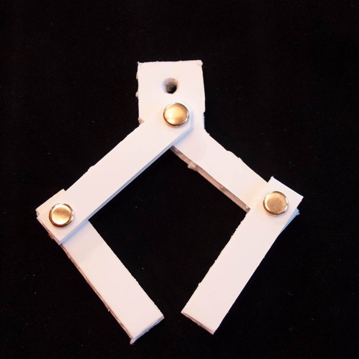
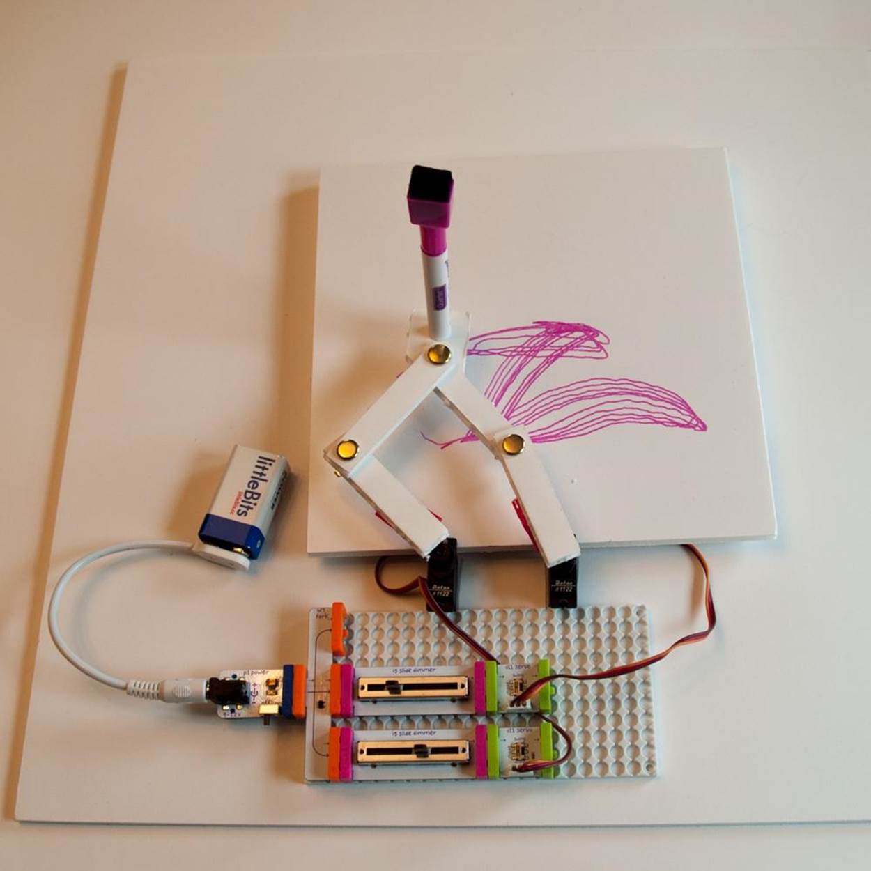
A plotter (Figure 5-1) is a machine that uses a pen or other art tool to draw a line image on paper or other physical objects by following a program or responding to real-time input.
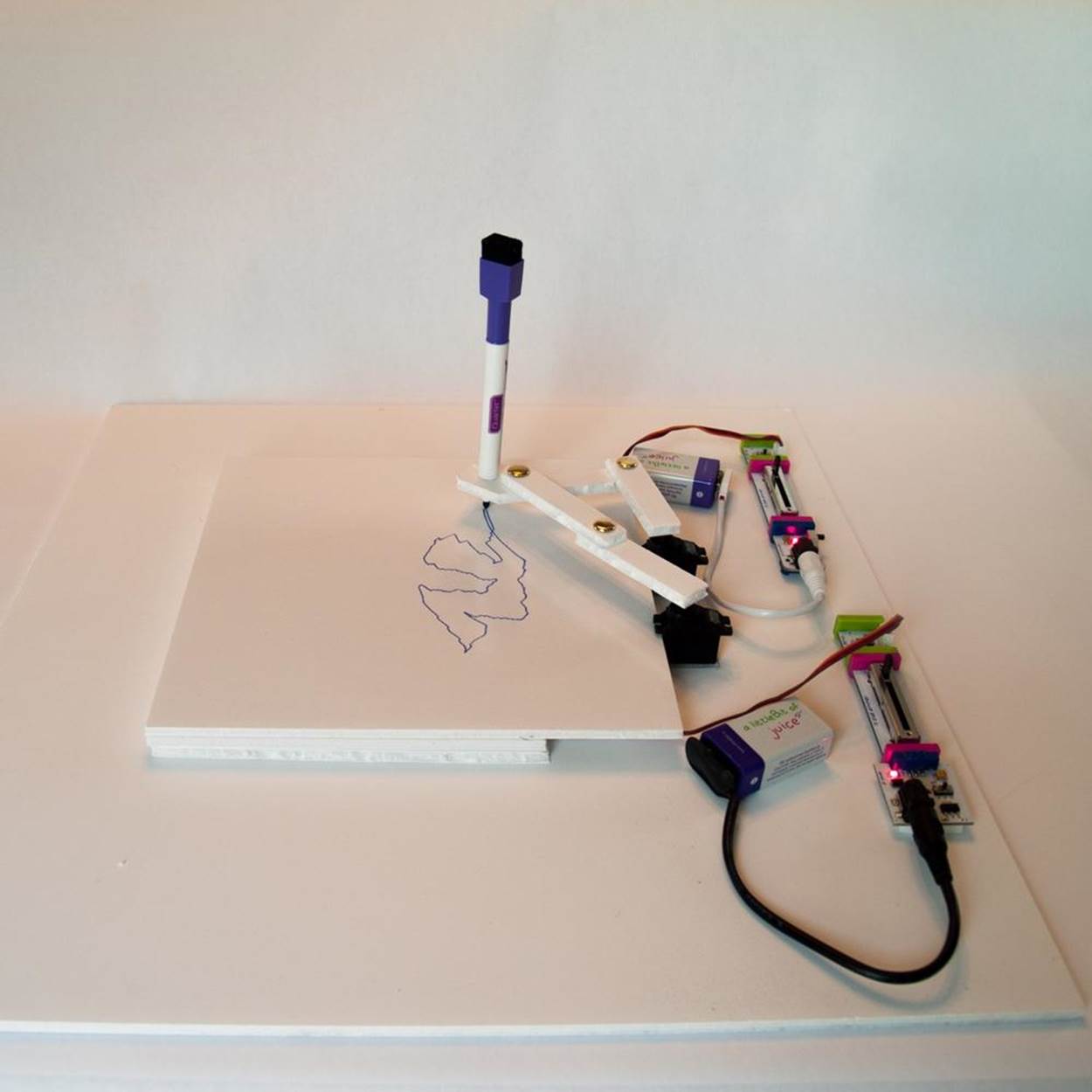
Figure 5-1. The littleBits plotter in manual Turn mode
What It Does
Because a pen plotter draws lines instead of printing dots like most modern printers, it can create a more exact copy of the image it is trying to reproduce. It is commonly used for large-scale drawings, such as engineering diagrams and architectural layouts, because it can accommodate long sheets or rolls of paper. And artists are tinkering with plotters because they can use many of the same kinds of pens, brushes, ink, and paint used to create images by hand.
Where It Came From
Plotters generally consist of a pen holder mounted on a set of two rails.
One hobby robot that uses this configuration is the WaterColorBot kit from Evil Mad Scientist (Figure 5-2). The WaterColorBot was designed by 12-year-old Sylvia Todd, star of Sylvia’s Super-Awesome Maker Show, a web series of video tutorials, who took her creation to the White House Science Fair in 2013. The WaterColorBot can dip a brush in paint from a child’s watercolor set and copy the movements of a human painter in real time, or follow a program created in Arduino. A similar Evil Mad Scientist plotter is the Egg-Bot. The pen in the Egg-Bot can follow the contour of any spherical or ovoid-shaped object that fits in its holder. One fan built a variation, the Mug Marker, which does the same for coffee cups.
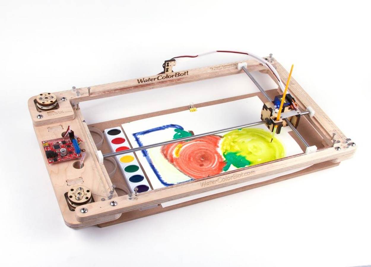
Figure 5-2. The WaterColorBot can reproduce human-created paintings or images from a program or in real time. Credit: Evil Mad Scientist/WaterColorBot.com.
Other plotters work like seismographs and move a pen across a paper using one or more arms. The desk toy Plotclock (Figure 5-3), designed at the FabLab in Nuremberg, Germany, holds a dry-erase marker in a double-handed grip. Elbows akimbo, Plotclock writes the time on a teeny whiteboard—then a minute later wipes the slate clean with an eraser and writes the time again. French artist/scientist Patrick Tresset’s single robotic arm, dubbed Paul, uses its camera eye to record a subject’s face and sketches out a portrait in its human developer’s own scribbly style. This style of plotter also includes the Pancake Bot, which we discussed earlier.
Some plotters can be configured to produce “original” art by reinterpreting images through their programming or the individual quirks of the drawing mechanism itself. The wall plotter, also called a vertical plotter, or v-plotter for short, is a pen holder suspended on a string from the corners of an upright drawing surface. Servo motors let out or reel in the string to raise and lower the pen and swing it from side to side. Unlike other kinds of plotters, it doesn’t matter how big the paper is—as long as there’s enough string, it can keep going. A group called Norwegian Creations built one of the first hanging drawbots using filled soda bottles as weights. Other examples include Der Kritzler from Germany, which writes on windows, and Hektor from Switzerland, which creates lovely robotic graffiti using spray paint.
![The Plotclock is an Arduino-controlled plotter arm that writes down the time each minute on a whiteboard. (Credit: thingiverse.com/joo[Johannes Heberlein])](robots.files/image154.jpg)
Figure 5-3. The Plotclock is an Arduino-controlled plotter arm that writes down the time each minute on a whiteboard. (Credit: thingiverse.com/joo[Johannes Heberlein])
How It Works
Like 3D printers, laser cutters, and programmable saws, sewing machines, and other CNC devices, plotters use CAD software to turn photos or graphics into computer code. A program translates the image into points on a grid, and then tells the plotter how to move to get the pen into the right place. Plotters that use Cartesian geometry plot the points on an x-axis (horizontal) and y-axis (vertical). It’s just like the geometry you learned in high school, when you drew lines and curves on a piece of graph paper by counting off boxes from the place where two guide lines crossed. Usually a z-axis motor lifts the pen up off the paper and lowers it down again.
Other types of plotters use polar coordinates that calculate the distance from one or more points on the machine. String plotters work this way. The poles are usually at the corners where the string is hung. Plotters with arms may use either, but like string plotters, the programming may be more complex than with straightforward Cartesian coordinates. That’s because the image may have to be built up by a pen that makes sweeping curves instead of traveling straight up or down.
BREAK THE CODE: TRAVELING SALESMAN PROBLEM
The Traveling Salesman Problem is one of the most studied puzzles in mathematics. It goes like this: a traveling salesman has to visit customers in a number of cities and then return back to the home office. What is the shortest path connecting every city on his itinerary that doesn’t intersect itself? As the number of cities grows, so does the complexity of the problem. In fact, some mathematicians believe that there is no exact answer, only approximations. Most often, the solution looks like a wiggly line that doubles back on itself over and over, like a maze.
The Traveling Salesman Problem can also be applied to the kind of plotters that draw a continuous line without lifting the pen from the paper. Instead of cities, the wiggly lines connect points on the drawing. By using programming based on the Traveling Salesman Problem, these kinds of plotters can create areas of dark and light shading by making the wiggly lines closer together or farther apart.
Making the Project
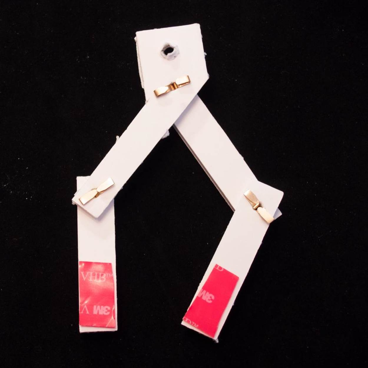
The littleBits Plotter is based on the Plotclock, the small drawing robot with a two-fisted grip. The arms are moved by servos, electronic motors that let you control how far the shaft turns and in what direction. Even though there is only one motor for each arm, they each have two degrees of freedom—they can bend at the “shoulder” and at the “elbow.” That gives this drawing machine four degrees of freedom in total. The real Plotclock can also tilt the pen up and away from the drawing surface, so it has five degrees of freedom. While the original design is programmed to write and rewrite the time using an Arduino, the low-tech adaptation is controlled by sliding dimmer switches. But this minimalist variation can still produce some interesting movements—both automated and manually controlled.
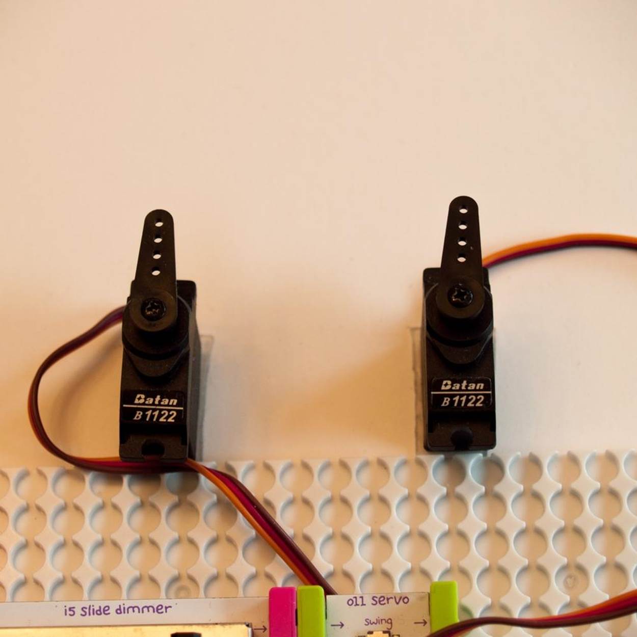
The littleBits servos you’ll be using to build your Plotclock look-alike have two modes, “Turn” and “Swing.” In Turn mode (Figure 5-4), the servo can be steered using a dimmer switch that controls the voltage of the circuit—turning to the left when the voltage is low, and to the right when the voltage is high. The sliding dimmer fits this project particularly well because the motion of your hand on the slider matches the motion of the servo back-and-forth. (The littleBits dimmer knob also works.) In Swing mode (Figure 5-5), the servo oscillates back and forth on its own and the dimmer controls the speed of the servo arm’s swing.
|
|
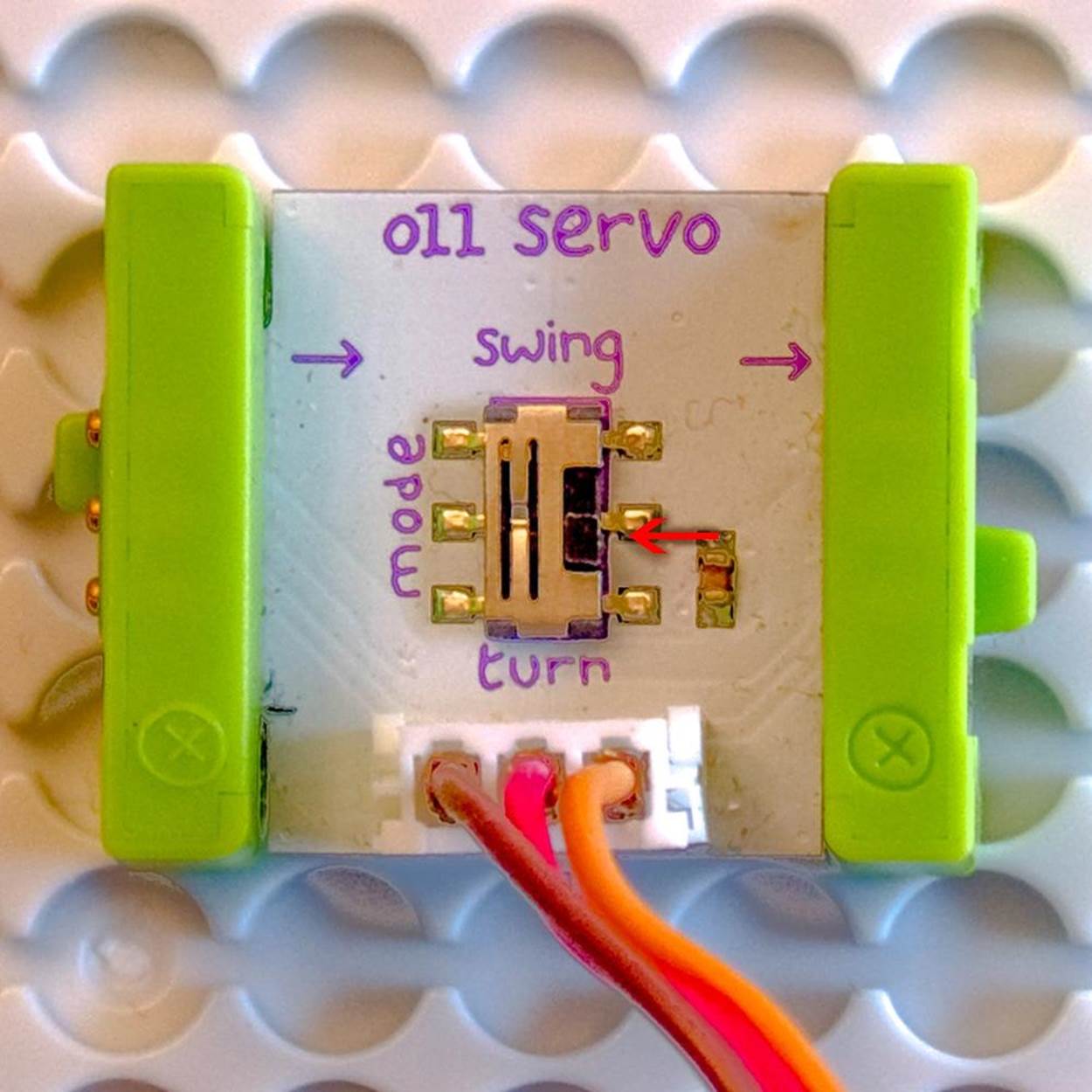
Figure 5-4. The littleBits servo in Turn mode.
|
|
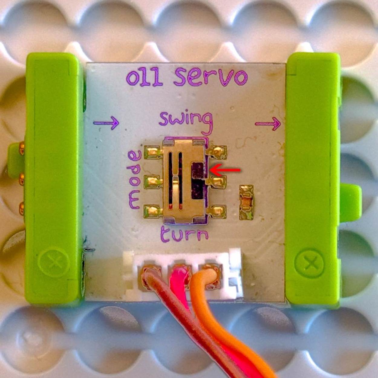
Figure 5-5. The littleBits servo in Swing mode.
NOTE
Don’t forget to document your work!
Project Parameters
§ Time Needed: 1–2 hours
§ Cost: $145 (about $15 for craft materials and $130 for reusable littleBits modules purchased individually or in a kit)
§ Difficulty: Easy
§ Safety Issues: A sharp box cutter or art knife is needed to cut the foam core
What You Need to Know
§ Skills You Already Have: Measuring, cutting, and gluing
§ Skills You Will Learn: Prototyping, building circuits, designing moving parts
Gather Your Materials
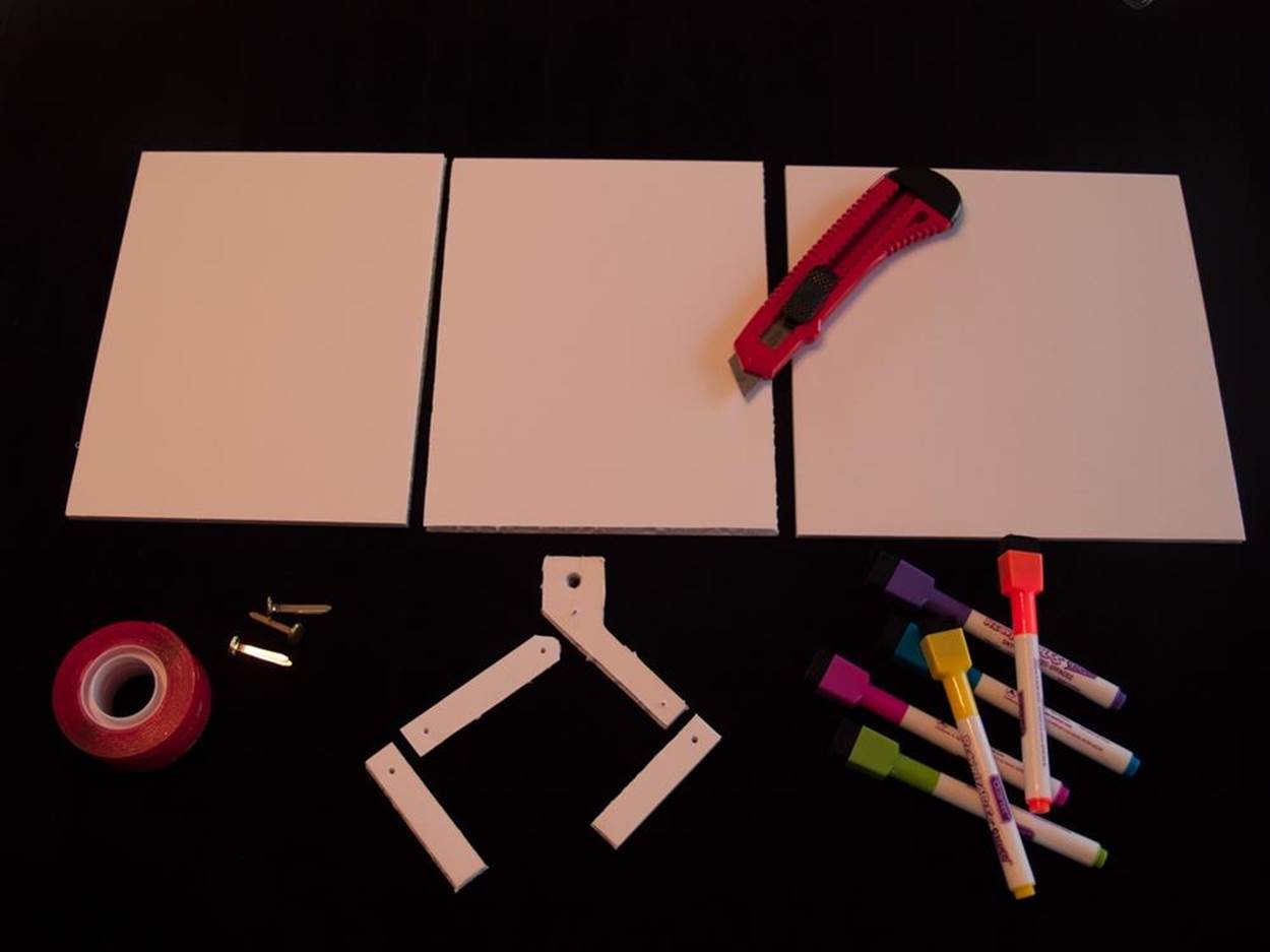
§ Drawing mechanism and platform
§ Sharp pencil for drawing lines and making holes in the foam core board
§ Metal or metal-edged ruler
§ Foam core board, enough for one 16 inch (40 cm) square and several smaller pieces
§ Dry-erase foam core board, enough for one 8-inch (20 cm) square (wide packing tape or slick peel-and-stick shelf paper on regular foam core works, too)
§ Three brads (two-prong metal paper fastener)
§ Dry-erase markers (fine point, such as Quartet or Board Dude brands)
§ Box cutter or X-Acto art knife
§ Small adhesive dots or white glue
§ Clear (gel-like) mounting tape, 1 inch (25.4 mm) wide
NOTE
See Building Robots with littleBits for more information about using removable adhesives that let you reuse your littleBits modules in other projects.
littleBits Modules
|
|
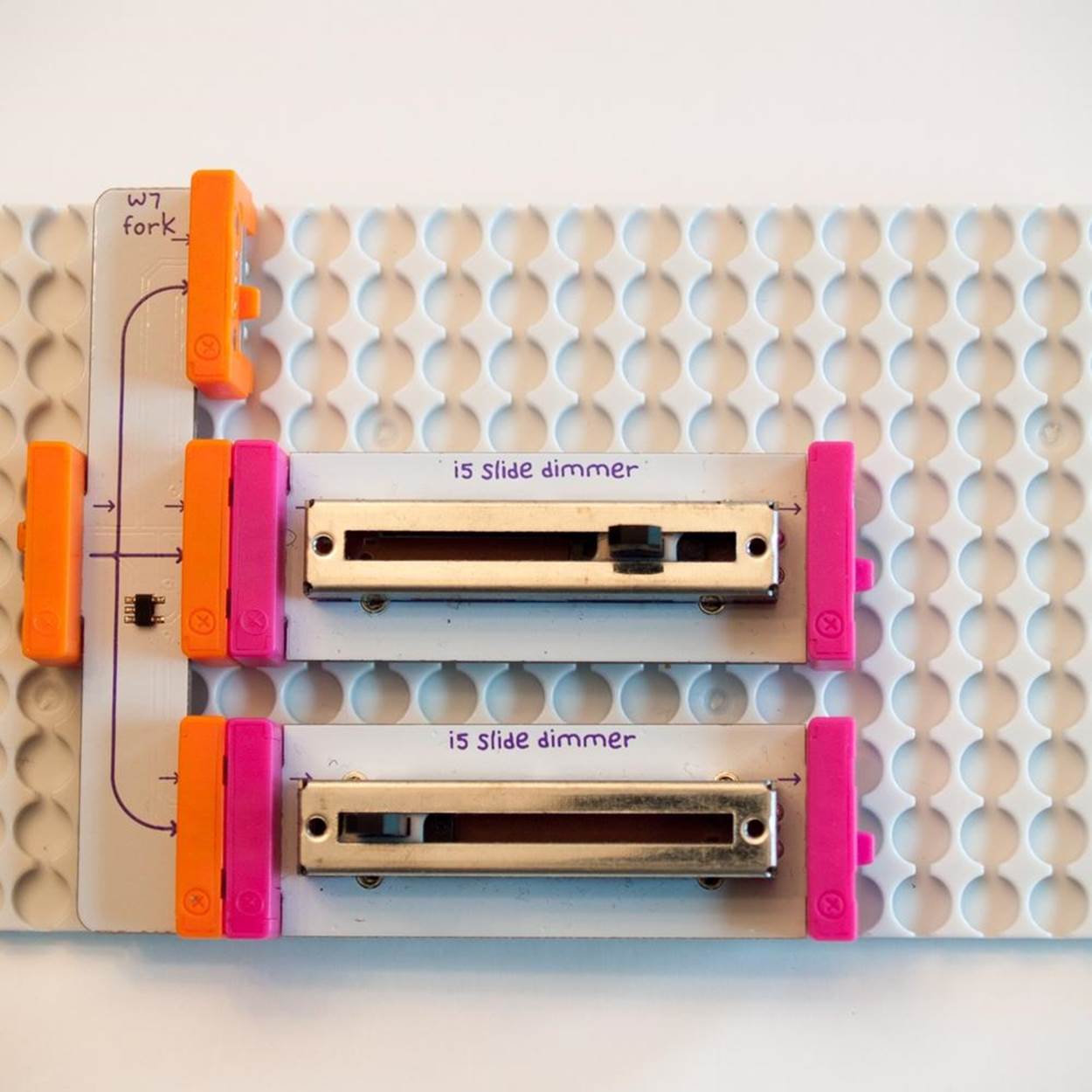
Figure 5-6. A littleBits Fork and two Slide Dimmers on a Mounting Board
§ 9V Battery and Cable (SKU 660-0006)—you need two, or one plus a splitter, such as the Split double wire or triple-branched Fork
§ Power Module (littleBits #LB-BIT-p1-POWER-v03)—you need two, or one plus a splitter, such as the Split double wire or triple-branched Fork
§ Slide Dimmer (SKU 650-0110) or Dimmer (SKU 650-0122)—two total
§ Servo Motors (# 650-0041)—two preferable, but see Step 7 for a one-servo variation
Optional littleBits Modules
§ Mounting Boards two-pack (#660-0005)
§ Pulse (littleBits #LB-BIT-i16-PULSE-v03)
§ Light Sensor (littleBits #LB-BIT-i13-LIGHTSENSOR-v03)
§ Inverter (littleBits #LB-BIT-w10-INVERTER-v03)
§ Randomizer (littleBits #650-0129)
Directions
Step 1: List Your Requirements
The goal of the project is to build a drawing machine modeled on the Plotclock that can move a pen around on its own or be controlled by littleBits electronic switches.
Step 2: Plan Your Project
There are lots of ways to use the Plotclock’s simple but effective arm design to create a drawing machine. Assembling it on a test platform gives you maximum flexibility to try out different configurations. The platform also gives you a place to anchor all your parts. Keep in mind that the servo motor bodies need to be anchored securely in place, so the only thing that moves when you turn them on are the rotating arms. You’ll also need to make sure the foam core arms are connected firmly to the servo arms, so they don’t wiggle or come loose as the mechanism starts to move.
NOTE
For free files to make your own 3D-printed holders to attach the battery and the servos to the littleBits mounting boards, see Plotter Linkbox.
Step 3: Stop, Review, and Get Feedback
This build is pretty straightforward and forgiving. There should be plenty of foam core if you make a mistake or want to try a different design. Pro tip: Elmer’s Dry Erase board is more expensive than a regular board, but cuts much more cleanly. Make sure to use a fresh blade on your box cutter or art knife. Use a metal ruler to guide you, and make several slow, steady swipes until you cut through all the layers, rather than bearing down on the blade.
Note that the measurements given below (in inches and centimeters) are taken from my prototype. A little deviation here or there should not affect it. If you want to make significant changes to the proportions, however, you’ll need to prototype your version yourself to be sure that it all fits together.
The only component you may have trouble with is the servo. Be careful when changing the arms to avoid loosening or bending them. Keep track of the little screw that holds the arm on. One handy trick is to place the servo on a dish or paper plate before you disassemble it. That way any small pieces from the servo will stay on the paper plate, and not roll off the table and get lost.
Step 4: Build Your Prototype
1. Measure and cut the following pieces from any kind of foam core board:
o A base about 16 inches square for the base.
o Two 8 inch (20 cm) by 6 inch (15 cm) rectangles to support the drawing surface.
o Two rectangular arm segments 1/2 inch (1 cm) wide by 2 1/2 inches (6 cm) long.
o One rectangular arm segment 1/2 inch (1 cm) wide by 3 inches (8 cm) long. Snip off the corners at one end to round it off a little.
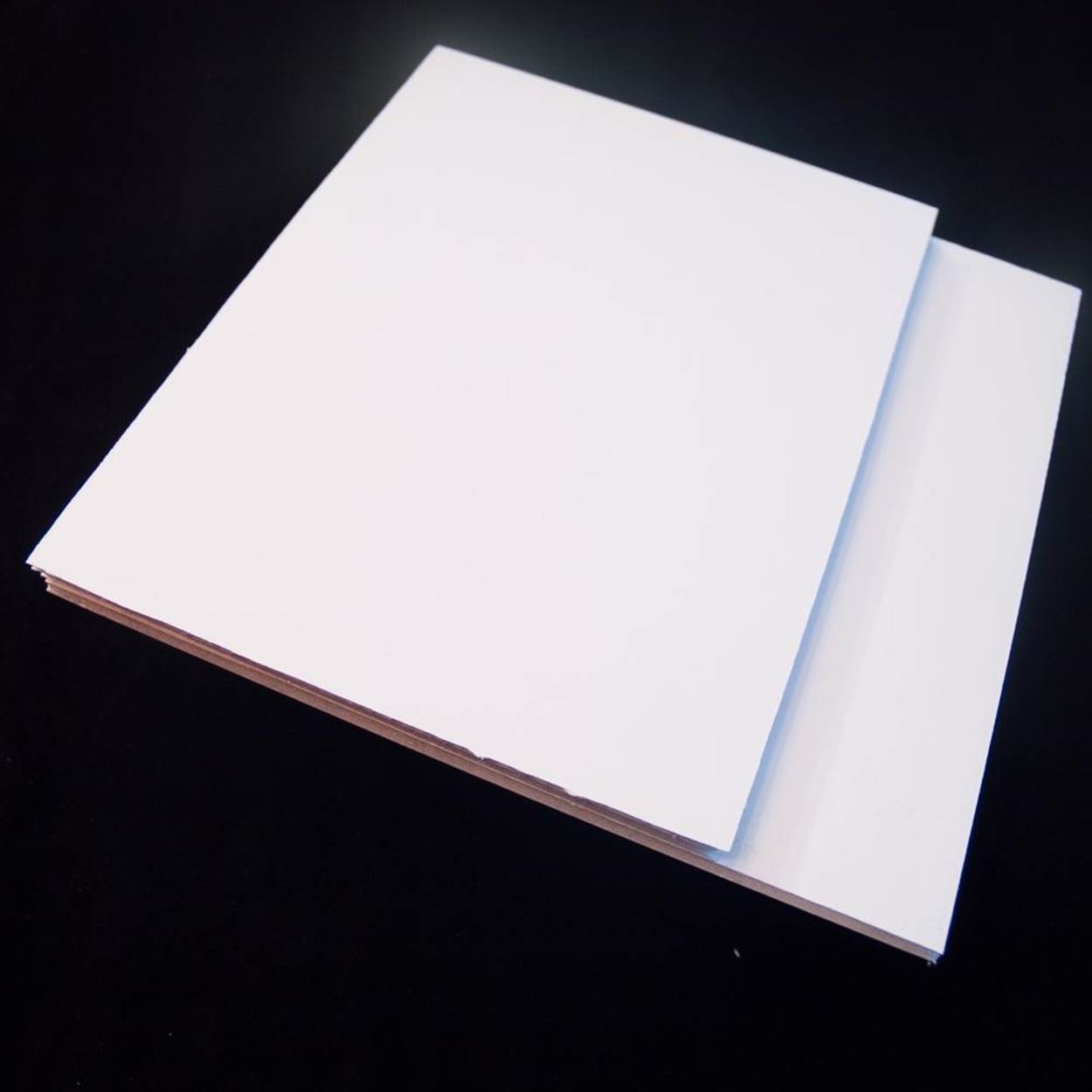
o Cut one 8 inch (20 cm) square for the drawing surface, using the dry-erase board. You can also use regular foam core board and cover it with dry-erase peel-and-stick paper or packing tape. Try to keep the surface as smooth as possible, making seams match exactly and avoiding air bubbles.
2. Looking at the arms from the point of view of the machine, the pen will be held in a hand attached to the right arm. It looks like a flag hanging on a pole. The bottom of the segment is a rectangle 1/2 inch (1 cm) across. One side is 2 3/4 inches (7 cm) long. The other side is 2 inches (5 cm) long. The bottom of the “flag” on the “pole” meets the shorter side at a 135 degree angle. The “bottom edge” of the flag is 1 1/4 inches (3 cm) long. The top of the “flag” is parallel to the bottom and the same length. The end of the flag is perpendicular to the top and bottom, about 1 inch (2.5 cm) across.
3. Take the two shorter arm segments. At their upper ends, use a sharp pencil to poke a small hole about 3/8 inch (1 cm) down, centered from side to side. Make the hole just big enough for the metal prongs of the brad to fit through and turn without scraping the sides of the foam core. Do the same at both ends of the longer rectangular arm segment.
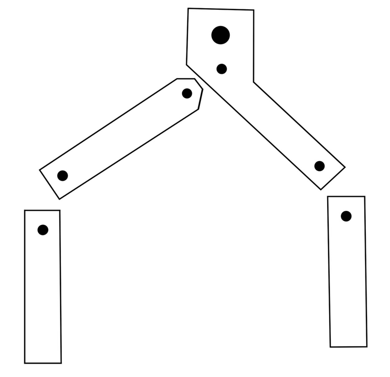
4. On the pen holder arm segment, poke one hole 3/8 inch (1 cm) from the bottom. On the “flag” end, poke another hole 1 inch from the top and centered, about 5/8 inch (1.5 cm) from either side. To make a hole for the pen, make a hole about 3/8 inch (1 cm) down from the top. Use the pencil to widen it until the pencil can almost pass through it.
5. Assemble the left arm by lining up the holes in one short segment and the bottom (nonrounded-off) end of the long segment. Make sure the short segment is underneath! Push the prongs of a brad through the guide holes.
6. Check to see that the segments can pivot freely around the prongs. If necessary, use the pencil to widen the hole a little. When the fit is acceptable, bend the prongs all the way back so they are flat against the back of the foam core. Then shorten the prongs by folding them in half so that the tips meet at the hole. Flatten as much as possible.
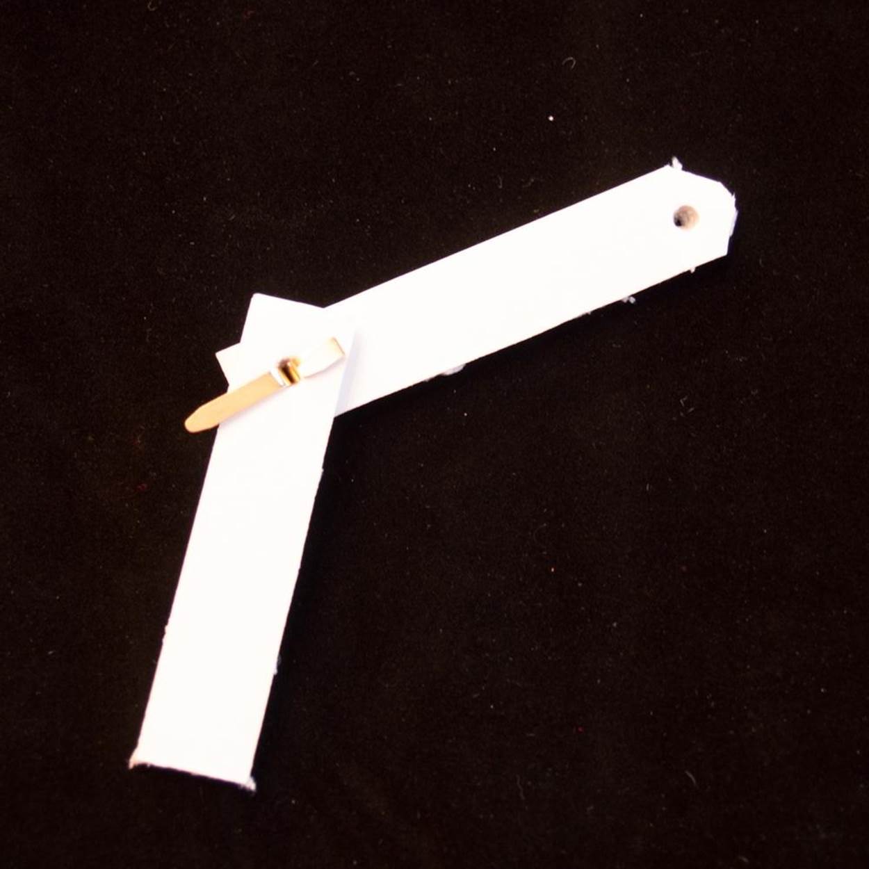
7. Assemble the right arm by lining up the holes in the remaining short segment and the bottom of the flagpole segment, with the short segment on the top (the reverse of the left arm). Fasten them with a brad as before. Finally, attach the two arms by lining up the remaining guide holes with the left arm over the right arm. Be sure the pen holder is underneath the other arm. Again, fasten with a brad the same way.
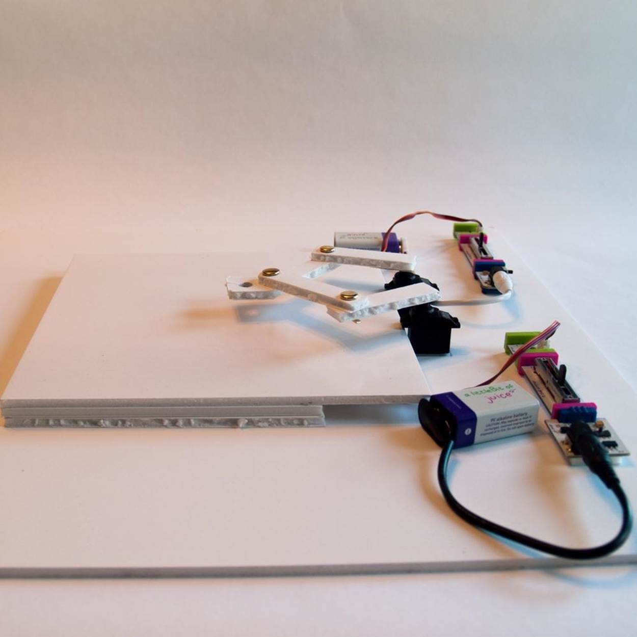
8. Next, build the drawing surface. Glue the two supporting rectangles together, one on top of the other. Then glue the dry-erase square on top—shiny side up—lining up three edges with the bottom supporting pieces so the extra hangs over on the fourth side.
9. Now prepare the servos. The single-prong attachment is the best one for this project. If it’s not already on, carefully unscrew and remove the attachment that is there and replace it with the one-pronged servo arm. Don’t put the screw back in yet—first you’re going to make sure the arms swing across the drawing area. If you’ve got mounting boards and a 3D-printed holder for your servos, attach them now. If not, take the clear gel-like mounting tape and cut a thin strip, a little narrower than the servo body. Stick it on the bottom of one servo. Attach the servo to the foam core platform about 3 1/2 inches from the edge closest to you, with the business end of the servo facing towards the center of the square, about 16 3/4 inches in from the left edge. Do the same with the other servo, but measuring it in from the right edge. Press the servo bodies down into the tape to attach them as firmly as possible.
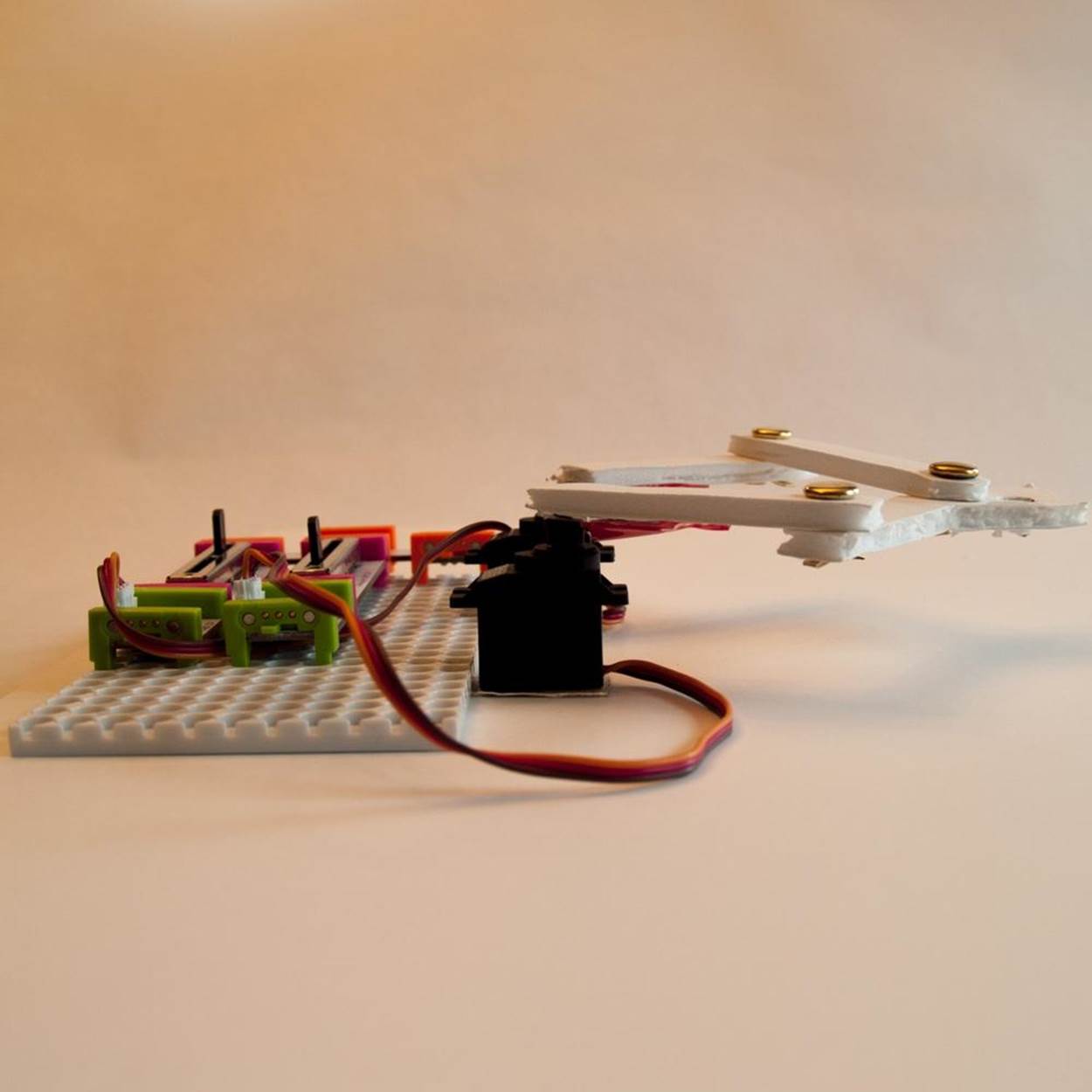
10. To adjust the swing, complete the circuit by connecting the batteries and power modules (or single battery/power module and a splitter) to the dimmer switches. Place one dimmer on the left and one on the right, lined up horizontally. The battery end of both setups should be pointing the same way (e.g., on the left with the dimmer on the right). Make sure the servos are in Turn mode by checking the little switch on the servo littleBit, and power them up. Push the left slider all the way to the left and the right slider all the way to the right. (If you are using the rotary dimmers instead of the sliders, turn the knobs accordingly.) Notice where the servo arms are pointing; they should be at 3 o’clock and 9 o’clock. Now push the sliders to the other extreme. Make sure the arms are close, but not so close that the foam core arms bump into each other when attached to the servo arms. If necessary, pull the servo arms off and set them at a better angle. When you’re satisfied, screw them in securely.
11. Attach narrow strips of the clear mounting tape to the undersides of the foam core arms. Press them down into the servos firmly enough to squeeze some of the tape into the holes on the servo arm. If needed, attach a second piece of gel tape to the underside of the servo arm and press upward into the foam core, sandwiching the servo arm in.
12. If you’re using a mounting board, attach it to the platform with a little more tape. Build your littleBits circuit by connecting the battery to the power module to the sliding dimmers and then to the servos.
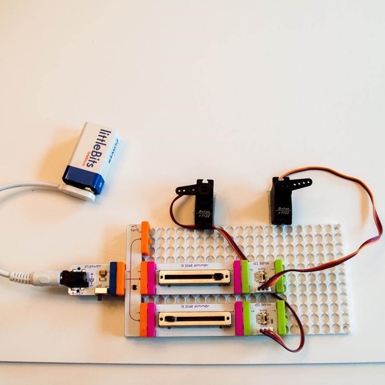
13. Slide the drawing surface towards the servos so the lip is centered up against their fronts. It should fit snugly under the little lip on the servos. You can mark on the platform where you want the drawing surface to sit, but it should stay put fairly well without having to glue it down. That makes it easier to slide it out to wipe it clean. Now, give it a test run!
Step 5: Test Your Design
Take the cap off one of the dry-erase markers and push the point down through the large hole in the pen holder. It should fit snugly and sit with the felt tip just touching the drawing surface. Set the servos to Turn and switch on the power. Try manipulating the sliders to move the pen back and forth, up and down. See if you can get it to make circles, loops, or lines. Can you draw a shape, a picture, or a letter?
To make it draw automatically, turn off the power, set the servos to Swing, and turn the battery back on. Watch what designs they make with the sliders at various settings. If you’ve got pulse modules, change the servos back to Turn mode, and see how the combination of pulse and slider affects the automatic drawings.
Step 6: Troubleshoot and Refine
The most common problems you are likely to have in running your drawing machine is to keep the foam core pieces connected to the littleBits and vice versa. More gel tape (and pressing the pieces together harder) is usually the answer. If needed, you can try using small nuts and bolts to hold the foam core onto the servo arms.
If your circuit isn’t working, make sure all the littleBits pieces are making a good connection with each other. The magnets should be touching. Sometimes the pulse setting will make the arms swing into each other. Try adjusting the relative settings of the pulse modules and the dimmers to try to avoid that, or move the servos farther apart.
Step 7: Adaptations and Extensions
A simpler and cheaper adaptation is to attach the arms to a foam core stand instead of the servo motors and move them manually, like a puppet. Attach them to the stand with brads, and make a knob from foam core or thumbtacks if desired. If you only have one servo, you can try a half-and-half approach by powering one arm and letting the other arm pivot freely on a similarly sized stand.
Other variations include moving the servos closer together or farther apart, or changing the proportions of the arm segments. (This is easier to do if you use the littleBits mounting boards and make 3D-printed battery and servo holders to fit.) Widen the “hand” of the drawing arm to accommodate two or three pens for a multicolor effect. Or instead of a reusable dry-erase board, substitute standard ink pens and paper. Use a large-size pad of sticky notes, or hook up the littleBits DC motor to make a roller that pulls a strip of paper across the drawing surface. If you connect the ends of the strip with tape, you can make a loop that circles around the drawing surface, letting you add multiple lines to the design.
To extend the project further, try adding one or more of the pulse, light sensor, inverter, or randomizer modules to change the way the arms are controlled. littleBits also has Arduino modules that let you add programming (see Project: Make FiberBot, an E-Textile Arduino Robot for a look at how Arduino works). Or if you’re skilled in working with electronic components, build your own permanent circuit with servos and dimmer switches.
PLOTTER LINKBOX
WaterColorBot
Egg-Bot
Mug Marker
Plotclock
Patrick Tresset’s robot Paul
Der Kritzler
Hektor
PlotterBot website listing many drawing robots
littleBits modules
Battery holder
Servo holder
Project: Make FiberBot, an E-Textile Arduino Robot
|
|
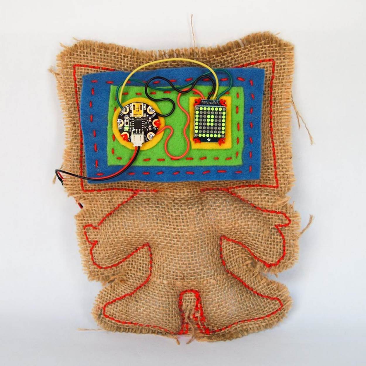
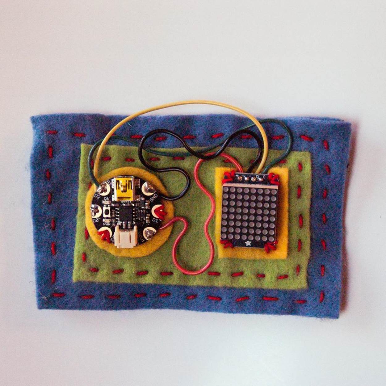
Figure 5-7. A finished FiberBot.
What Are E-Textiles?
E-textiles combine sewable electronic components and fiber art.
What It Does
E-textiles can receive input from sensors and switches and react with the physical environment by moving, flashing lights, producing sounds, and so on, using Arduino-compatible hardware and Arduino programming.
Where It Came From
The Arduino microcontroller board was developed in 2002 by software designer Massimo Banzi for his students at the Interaction Design Institute Ivrea in Italy. His goal was to create a tool that would help nontech-savvy students create electronics projects as quickly and easily as possible. There were already a few microcontrollers being used for physical computing—making physical objects respond to commands and interact with their environment. But Banzi wanted something cheaper, more powerful, and compatible with Mac and Linux operating systems as well as Windows. With the help of a team of students and colleagues, Banzi based the Arduino (named after their favorite local bar) on a programming language from MIT called Processing that helped beginners create interesting graphics. He borrowed Processing’s easy-to-use integrated development environment (IDE), and adapted it to work with a specially designed microcontroller board that could work with lights, motors, and other physical outputs. To speed up the development process, Banzi’s team also made Arduino open source, which means anyone can build their own or come up with their own variation.
Today Arduino is one of the most popular tools for robotics hobbyists and makers of all kinds. One of the things hobbyists like to do with Arduino is use it to add programmable controls (and often sensors and processors to allow them to operate autonomously) to old toys. The small size and low cost of Arduino boards and Arduino-compatible clones make it possible to embed them into RC cars, stuffed dolls, and more. Many Arduino-compatible systems attempt to miniaturize the components even more. Some, likeTinyDuino, do it by creating modular systems that let you choose only those features you need and connect them by stacking them together. Others make all-in-one boards but usually use a smaller microcontroller, and limit the number of input/outputs they have, to save space.
That’s the route taken by pared-down sewable microcontroller boards. Designers use Arduino to create clothing and decorative accessories that can respond to their environment or your control. They use conductive thread and fabric to build circuits right into the fabric of their design, often in visible and decorative ways. And they incorporate sewable microcontrollers like MIT professor Leah Buechley’s line of LilyPad components (developed with and manufactured by SparkFun). While most e-textiles are just for fun, some are also useful. For example, Leah Buechley’s Turn Signal Jacket can be worn while bicycling to alert drivers behind you. And design student Kathryn McElroy of the School of Visual Arts created a handbag covered in flashing colored lights that lets you know if you forgot your phone or keys. A small Arduino-based circuit board inside the handbag can read a signal from RFID (radio frequency identification) tags you affix to your personal belongings. Then you can program the microcontroller to create different animated patterns, depending on what item it’s detecting (or not). You could set it to flash red if it doesn’t get a signal from your eyeglass case, for instance.
How It Works
Arduino boards and their clones come with pins, which are really sockets where you can plug input devices (like light sensors or dimmer switches) and output devices (light motors and LEDs). Programming an Arduino board involves telling it what pin to look at for input data, and what pin to send output instructions to. The Arduino language itself is relatively easy to understand. It doesn’t take long to figure out how to write simple commands and programs, which are known as sketches. There are even drag-and-drop graphical versions of Arduino under development, such as Scratch for Arduino and Ardublocks, which make working with Arduino boards even easier.
Sewable Arduino boards like LilyPad Arduino are very versatile. Because they’re smaller, simpler, and less expensive than the standard Arduino boards, they’re a popular way for beginners who already know traditional crafts like sewing and crochet to add cool interactive features to their fiber art. They feature large holes surrounded by big metal pads, which make it easier to create electrical connections using conductive thread. The trade-off is that the mini boards can’t do as much as a full-sized board. The LilyPad Arduino line of components are very good for making lights blink and shine in programmed patterns or in response to stimuli like motion, sound, or the beating of a heart. But they’re limited when it comes to more powerful applications such as making a robot move.
In 2013, Adafruit Industries, a company founded by MIT-trained engineer Limor “Lady Ada” Fried, came out with a line of ultra-tiny microcontroller boards that could handle things like servo motors as well as other interesting kinds of components. Like the LilyPad Arduino, and the sewable Flora and Gemma (and the nonsewable Adafruit Trinket) are smaller and thinner than regular Arduino boards. That makes them ideal for for beginning projects and tighter spaces, including programmable jewelry, 3D-printed toys, and ragdoll hacks.
ARDUINO LINKBOX
Arduino
Leah Buechley’s LilyPad Arduino
Kathryn McElroy’s Chameleon Bag
Scratch for Arduino
Ardublock
Adafruit
§ Getting Started with Arduino by Massimo Banzi (2011, Maker Media)
§ Make: Arduino Bots and Gadgets by Kimmo Karvinen and Tero Karvinen (2011, Maker Media)
§ Make: Basic Arduino Projects by Don Wilcher (2014, Maker Media)
Making the Project
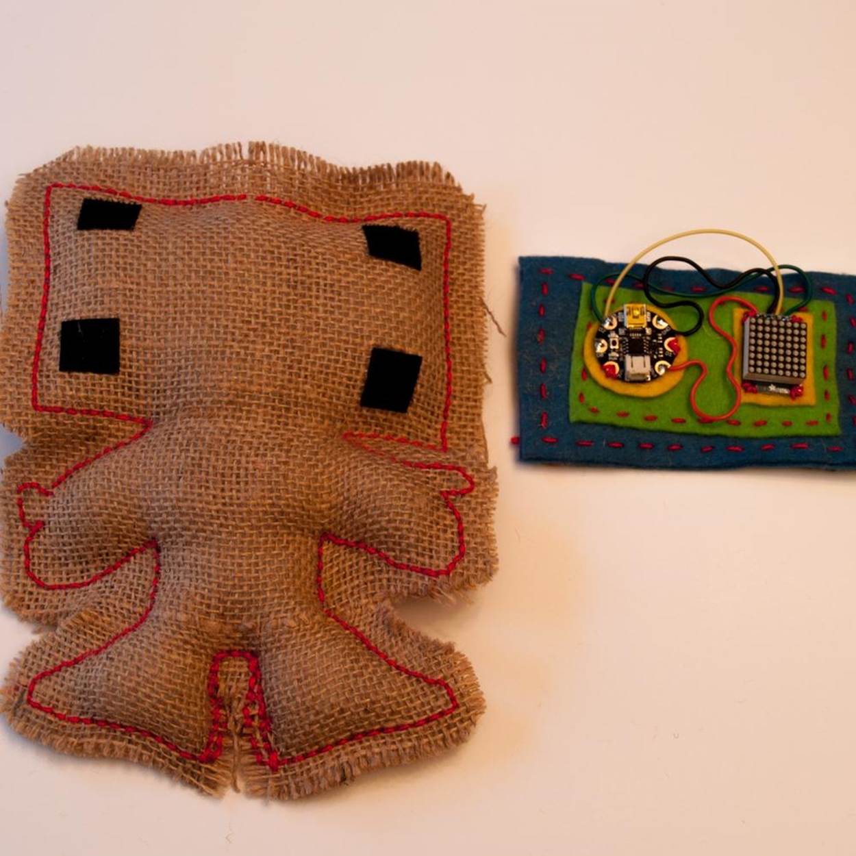
The FiberBot’s Borg-like electronic left eye is really an Adafruit Gemma microcontroller. Its animated right eye is an LED screen, also from Adafruit. You’ll learn how to program the Arduino-based Gemma to run an EyeRoll animation, or create one of your own. Strictly speaking, this isn’t an e-textile project, because the LED matrix isn’t set up to use conductive thread. But you’ll get to use your sewing skills to create the basic hand-stitched, stuffed FiberBot body and attach the circuit to it. It’s a challenging project for a beginner, but when you’re done you’ll be able to say you know how to work with entry-level Arduino devices.
NOTE
The Adafruit computer programs reprinted here are available free to the public through a BSD open source software license. They ask that any use of the code include the following message: “Adafruit invests time and resources providing this open source code. Please support Adafruit and open-source hardware by purchasing products from Adafruit!”
NOTE
Don’t forget to document your work!
Project Parameters
§ Time Needed: 3–4 hours (less for experienced robot builders; more if you’re a newbie)
§ Cost: $20–$30
§ Difficulty: Moderate
§ Safety Issues: See Project: Make a Souped-Up Solar BEAM Wobblebot for safety issues regarding soldering.
What You Need to Know
§ Skills You Already Have: Sewing, downloading and unzipping computer files, soldering (see Project: Make a Souped-Up Solar BEAM Wobblebot)
§ Skills You Will Learn: Setting up an Arduino device and working with an Arduino program
Gather Your Materials
Note that the number in parentheses indicates the Adafruit product number.
|
|
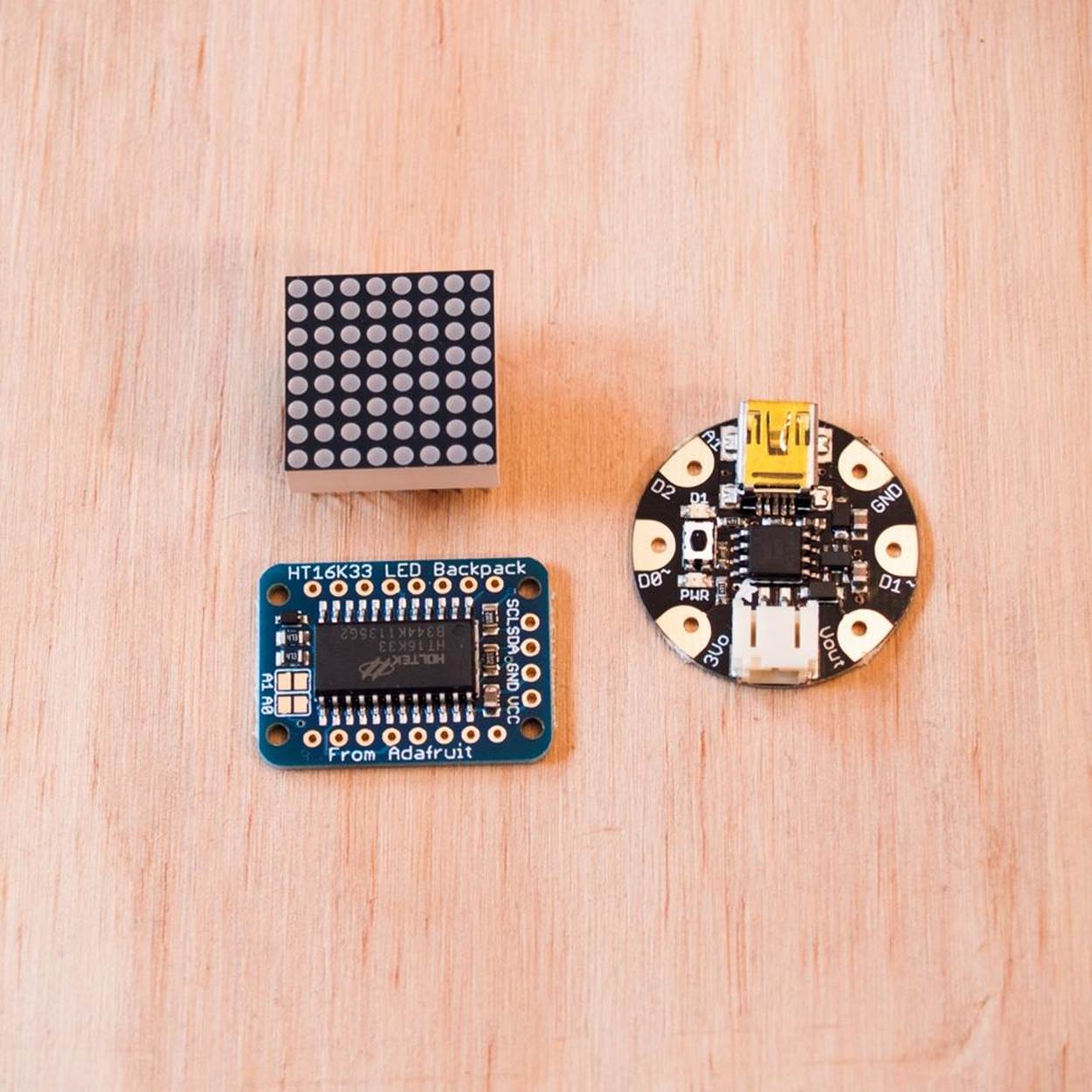
Figure 5-8. The Adafruit Mini LED Matrix (top left), the Matrix backpack (bottom left), and the Gemma microcontroller (bottom right)
§ Adafruit Gemma microcontroller (#1222)
§ Adafruit Mini (0.8 inch) 8×8 LED Matrix with backpack (#872 or other colors in same size)
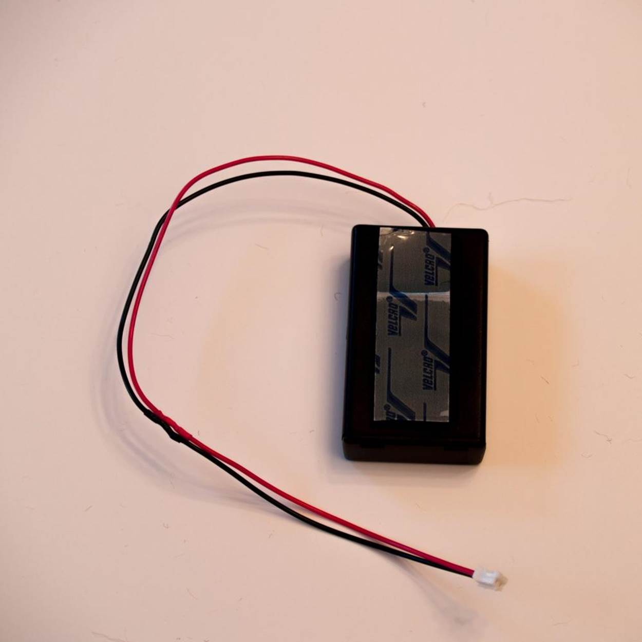
§ Adafruit 3 x AAA battery holder with on/off switch and 2-pin JST connector cable (#727)
§ Mini USB cable (#260—a cell phone cable that fits will work, too)
§ Computer (preferably Windows or Mac) with Internet
§ Wire (preferably solid; 22 AWG or thinner hookup wire, or 30 AWG wire wrap)
§ Wire cutter and wire stripping tools
§ Soldering iron and solder
The Fabric Body
§ Paper and pen
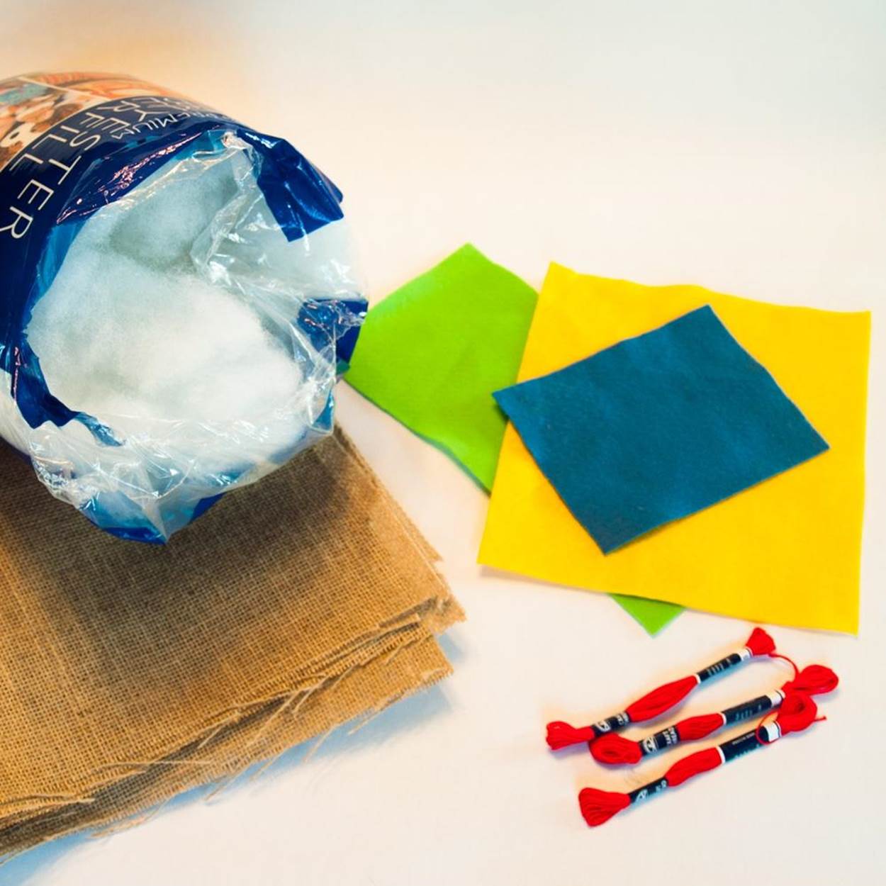
§ Burlap (used burlap bags are good), enough to make two 8 × 10 inch (20 × 25 cm) pieces
§ Felt (three or four colors)
§ Straight pins
§ Embroidery needle and/or large sewing needle, size 3 or 5—must fit through the holes on the Gemma
§ Scissors
§ Embroidery yarn
§ Embroidery needle (thick, with an eye large enough for a full strand of embroidery yarn)
§ Fiber fill stuffing for the body (can also use fabric scraps or dryer lint)
§ Peel-and-stick Velcro tape or tabs
A NOTE ON WIRE AND BATTERIES
The numbers you see listed for different kinds of wire refer to the thickness, or gauge (sometimes listed as AWG, for American Wire Gauge). The higher the number, the thinner the wire. The holes on some of the components for this project are rather small, so 22 AWG is the thickest you will want to use. That’s the gauge of standard hookup wire, an all-purpose wire you can buy insulated in several colors.
Also look for solid wire as opposed to stranded. For soldering components, solid wire is easier to work with. Stranded wire is made up of many ultra-thin filaments that can fray and tear, making it harder to poke the wire through small holes. As a shortcut, you can buy a box of precut, prestripped breadboard jumper wires and have a supply of short wires in multiple colors, already stripped (to expose the wire inside the plastic insulation) and ready to go.
When it comes to batteries, there are a few different choices that will work, but for beginners the best choice is the recommended three AAA batteries. The battery holder from Adafruit has a JST plug already attached, as well as an on/off switch, saving you a few more parts to find and solder on. Coin cell batteries, recommended for some other projects using the Gemma, take up less space but don’t deliver enough current to power the LED matrix.
You may see that Adafruit recommends a lithium-ion polymer battery for similar projects. The LiPo battery costs just a little more than a AAA battery holder and batteries, but is much smaller, lighter, and rechargeable. However, LiPo batteries also have some safety concerns—their covering is soft, and they can catch fire if bent, crushed, punctured, or short-circuited. They also need to be recharged carefully, preferably with a special charger like the USB model Adafruit sells. That’s why we don’t recommend using a LiPo battery for beginners.
Directions
Step 1: List Your Requirements
There are two goals to work on in creating this project: making a soft “robot body” from fabric, and integrating an Arduino board and some electronics to kick it up a notch. Getting those two goals to work together well is the challenge. This version is just one solution—once you understand a little of the technology involved, feel free to give this project your own stamp.
Step 2: Plan Your Project
Use the pattern in this book or design your own. Just make sure the “face” of the FiberBot fits on the body you choose. All the electronics will get sewn onto the rectangle-shaped face, which gets attached to the FiberBot head with Velcro, so you can take it off to program it or to use on an alternate body. The battery pack plugs into the Gemma with a cable long enough to hang on the FiberBot’s back with more Velcro. If you’re designing your own body, make your own pattern using a heavy marker that will be visible through the burlap.
Step 3: Stop, Review, and Get Feedback
Setting up the Gemma for the first time and initializing the LED matrix can be confusing. If you need help, check out the Adafruit Learning System online tutorials. There’s much more information there than you will need to know to get this project up and running, but that’s the first place to turn. Adafruit also has a Customer Support Forum that you can join to get answers to your questions from the company’s tech experts and experienced customers. It helps to look through the tutorials first in order to frame your question. You should get a response within a few hours.
ADAFRUIT TUTORIALS AND SUPPORT
§ Gemma setup
§ Drivers for Windows computers
§ Installing Arduino
§ Setting up an Arduino Library
§ LED Matrix animation how-to
§ LED Matrix animated robot face code
§ Adafruit Customer Support
Step 4: Build Your Prototype
First, assemble the electronic circuit.
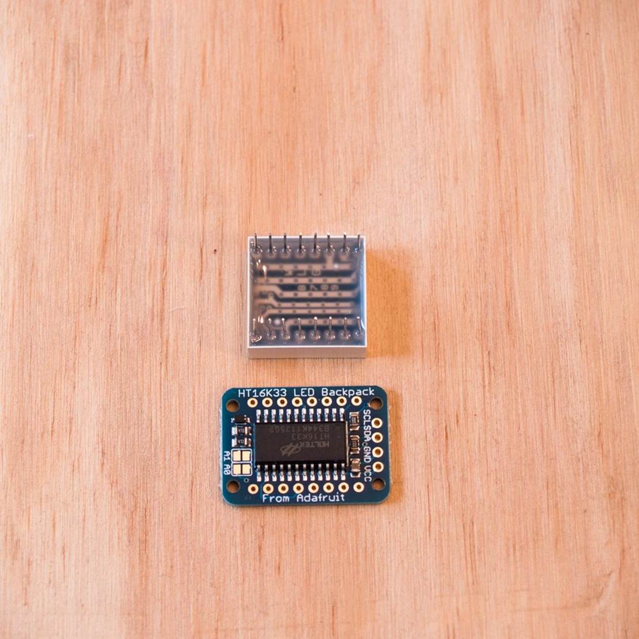
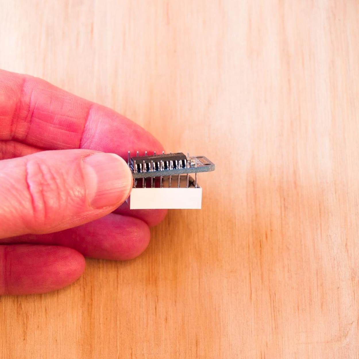
1. The LED Matrix comes with a “backpack” circuit board that lets you control its 64 pixels with some simple Arduino programming (which you’ll learn more about below). The two must be soldered together. Put the LED Matrix face down on your work surface so the 16 thin wire leads are sticking up. To hold it steady, you can rest it between the jaws of a clamp or pliers (they don’t need to be tight). Then take the circuit board—with the black rectangular chip facing up, away from the LED Matrix—and slide it down onto the LED Matrix by carefully matching up the leads with the 16 holes along the circuit board’s sides. It doesn’t matter which side is left or right. Next, heat up the soldering iron, tin the tip, and touch it to the first lead for a second or two.
Then push the solder underneath the tip just until it flows around the wire into a volcano shape. Let it cool for a few seconds, then continue down the rows on both sides the same way, being careful not to let the solder of one lead run into the next. If it does, see the discussion on desoldering in Soldering Cheat Sheet to find out how to clean it up and prevent bridging between two points. When you are done soldering all the leads, use wire cutters to trim each one back to just above the little cone of solder.
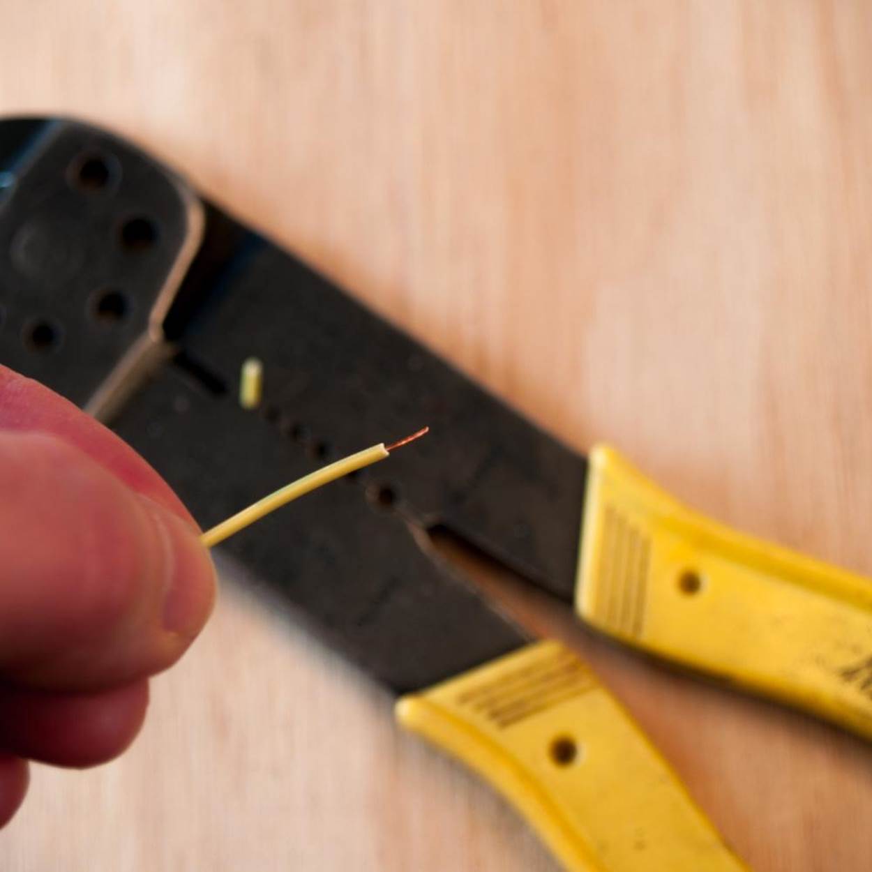
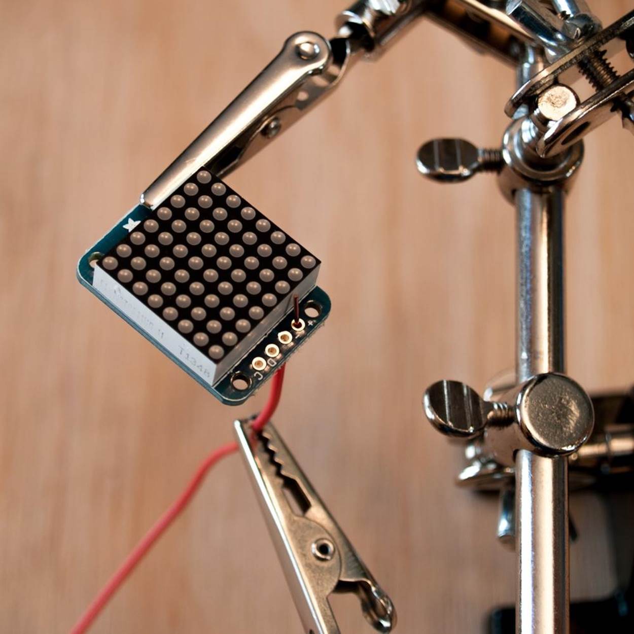
2. Next you’ll use the hookup wire to connect the LED Matrix and backpack to the Gemma. Cut four 4 inch (10 cm) lengths, preferably different colors. Strip the insulation off about a 1/4 inch (1 cm) from each end. Use one arm of your helping hand tool to hold the LED Matrix flat, and the other to hold the first wire sticking up through the first hole. Solder as before. Do the same with the rest of the wires. When done, trim all the leads.
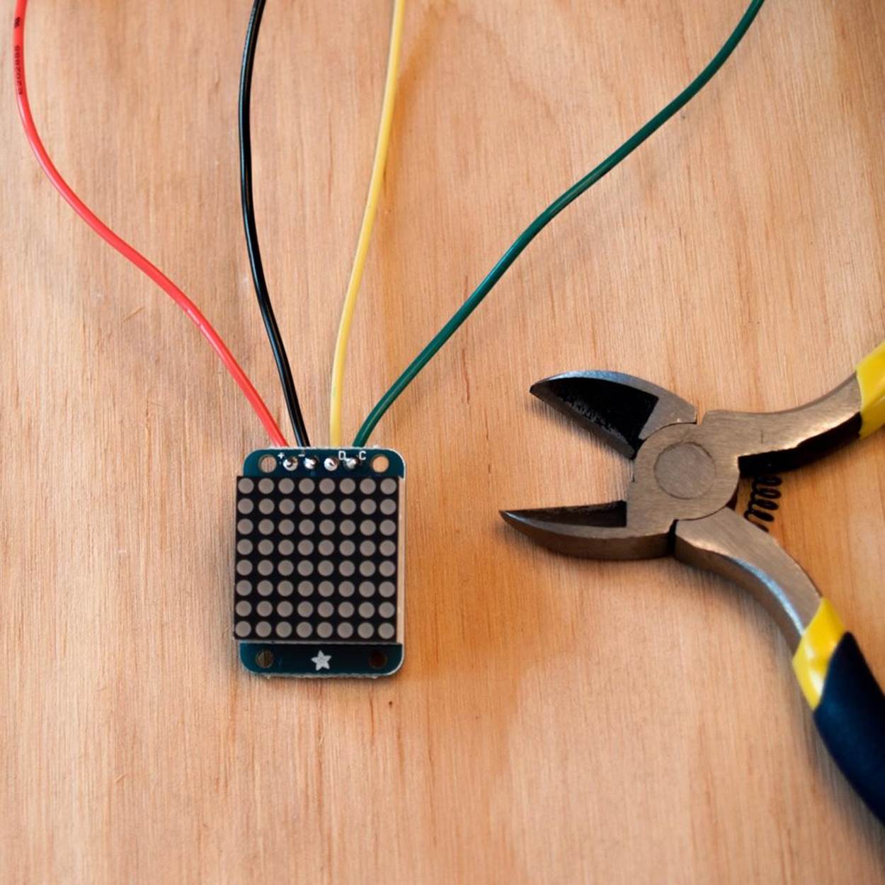
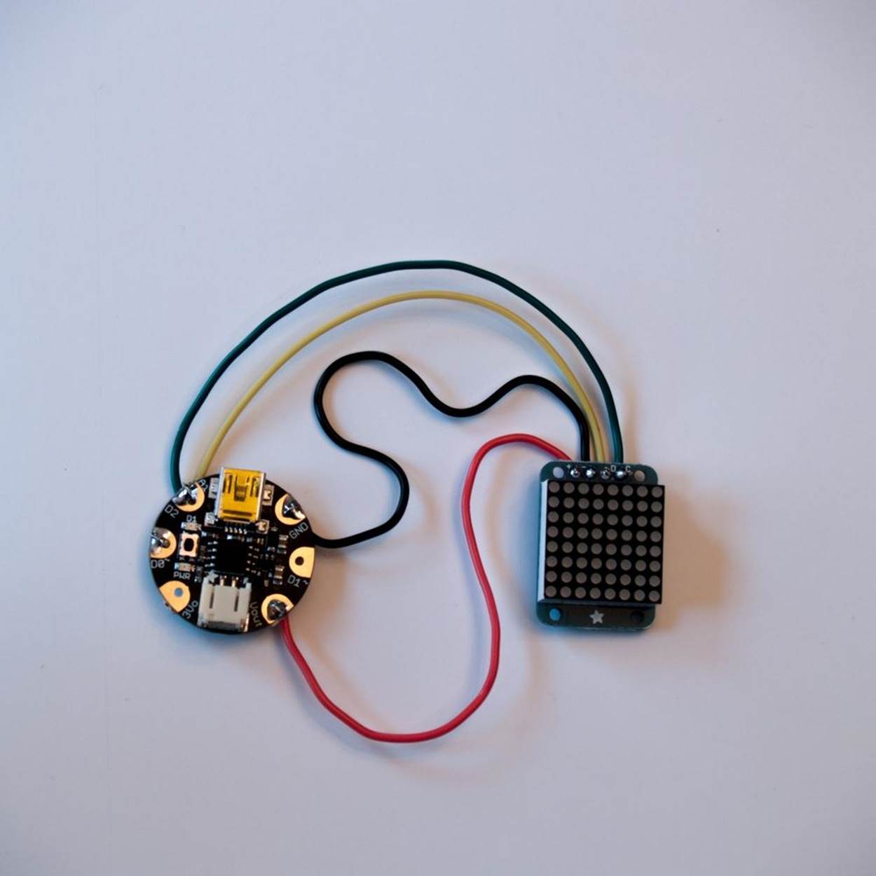
3. Now it’s time to connect each wire from the LED Matrix to the Gemma. Looking at the LED Matrix with the lights facing up, notice that the holes for the wires are marked “+,” “,” “D,” and “C.” The Gemma has six soldering pads, three on each side. You will be using four and leaving two empty. With the Gemma face up, its USB connector at the top, this is how the wires will be attached.
|
|
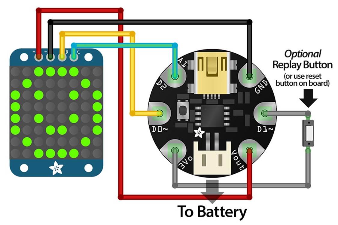
Figure 5-9. Credit: Adafruit and Fritzing.
o The + wire (red in the photo) will be connected to the bottom pad on the right (marked Vout).
o The − wire (black in the photo) will be connected to the top pad on the right (marked GND).
o The D wire (yellow in the photo) will be connected to the middle pad on the left (marked D0).
o The C wire (green in the photo) will be connected to the top pad on the right (marked D2).
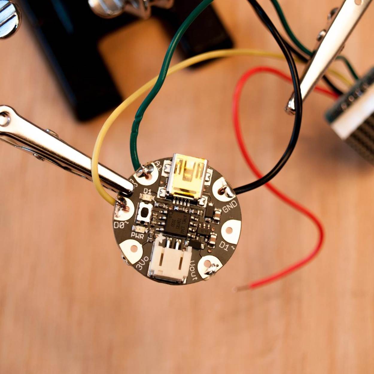
Soldering the wires from the LED matrix onto the Gemma is a bit tricky, since the holes are sized for sewing, not soldering, so it helps to pre-tin them. Use the third hand tool to hold the Gemma in place, and cover the pads listed above (and only those pads) with a thin layer of solder. Then take the first wire and poke it through the correct hole from below, double-checking that you have the right one. Bend the wire over to hook it onto the first pad. Use the tip of the soldering iron to push the wire down into the blob of solder on the appropriate pad, adding a little more from the top until the wire is covered. Do the same with the other three wires.
4. At this point, you may want to go to “Step 5: Test Your Design” to load the Arduino software onto your computer, plug in the Gemma, and make sure it and the LED Matrix are working properly. Otherwise, you can finish building the body of your FiberBot and work on the programming later.
Next, make the FiberBot body and attach the Gemma-LED Matrix circuit to it.
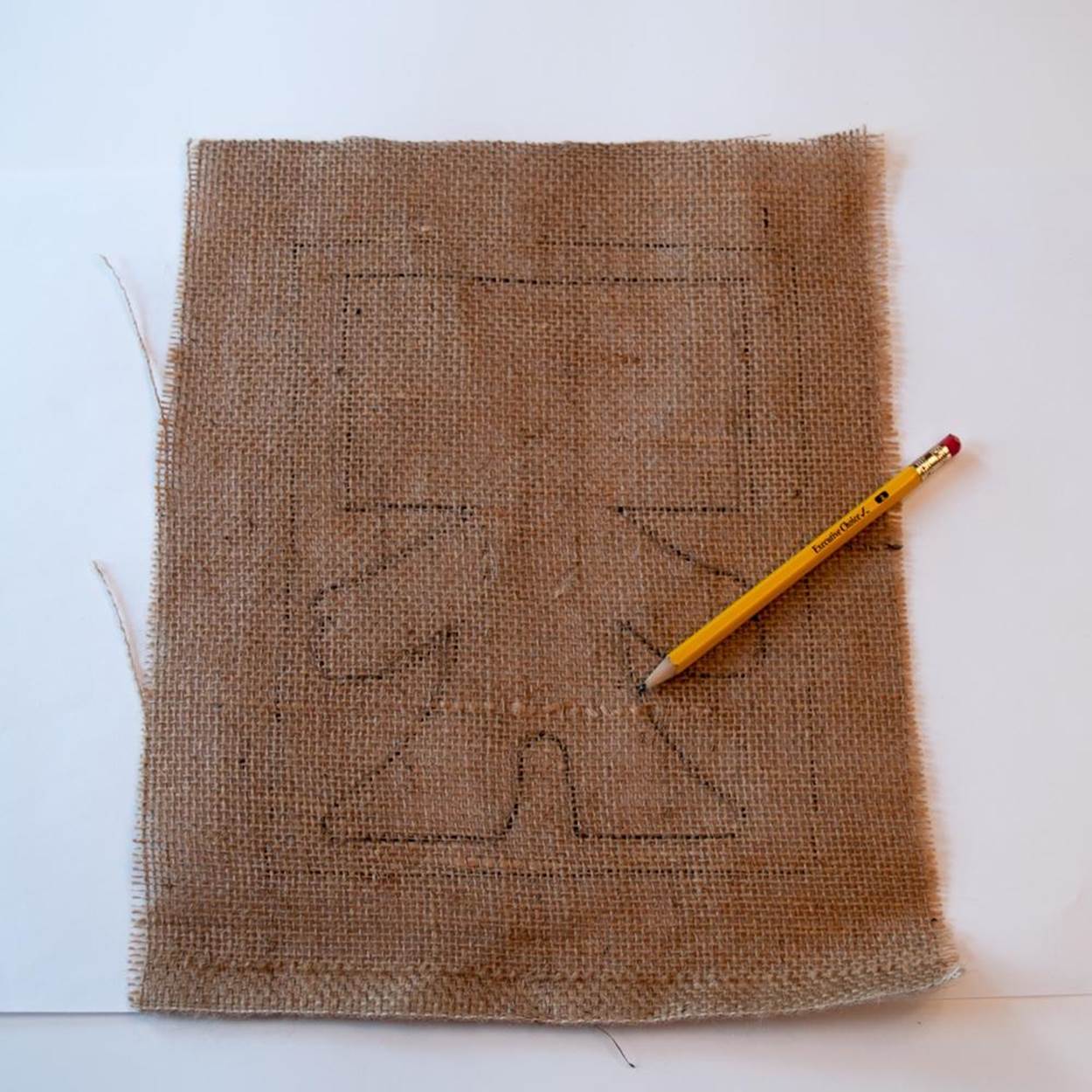
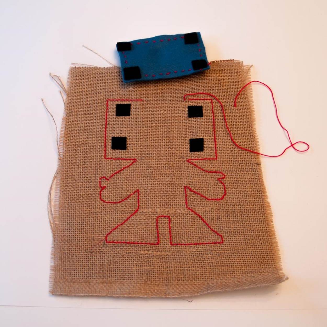
1. FiberBot’s raggedy burlap body was inspired by the little androids in the movie 9 by Tim Burton protege Shane Acker. Burlap is inexpensive and easy to cut and sew, but you’ll need to take care to prevent fraying. Print out the FiberBot Pattern on regular-sized printer paper (or enlarge and copy the pattern below) and place it over your pattern. The height of the bot from head to foot should be 8 inches (20 cm). Trace the outline of the bot onto the burlap with a soft pencil. Place it on top of the other piece of burlap, matching the edges, but don’t cut it out yet!
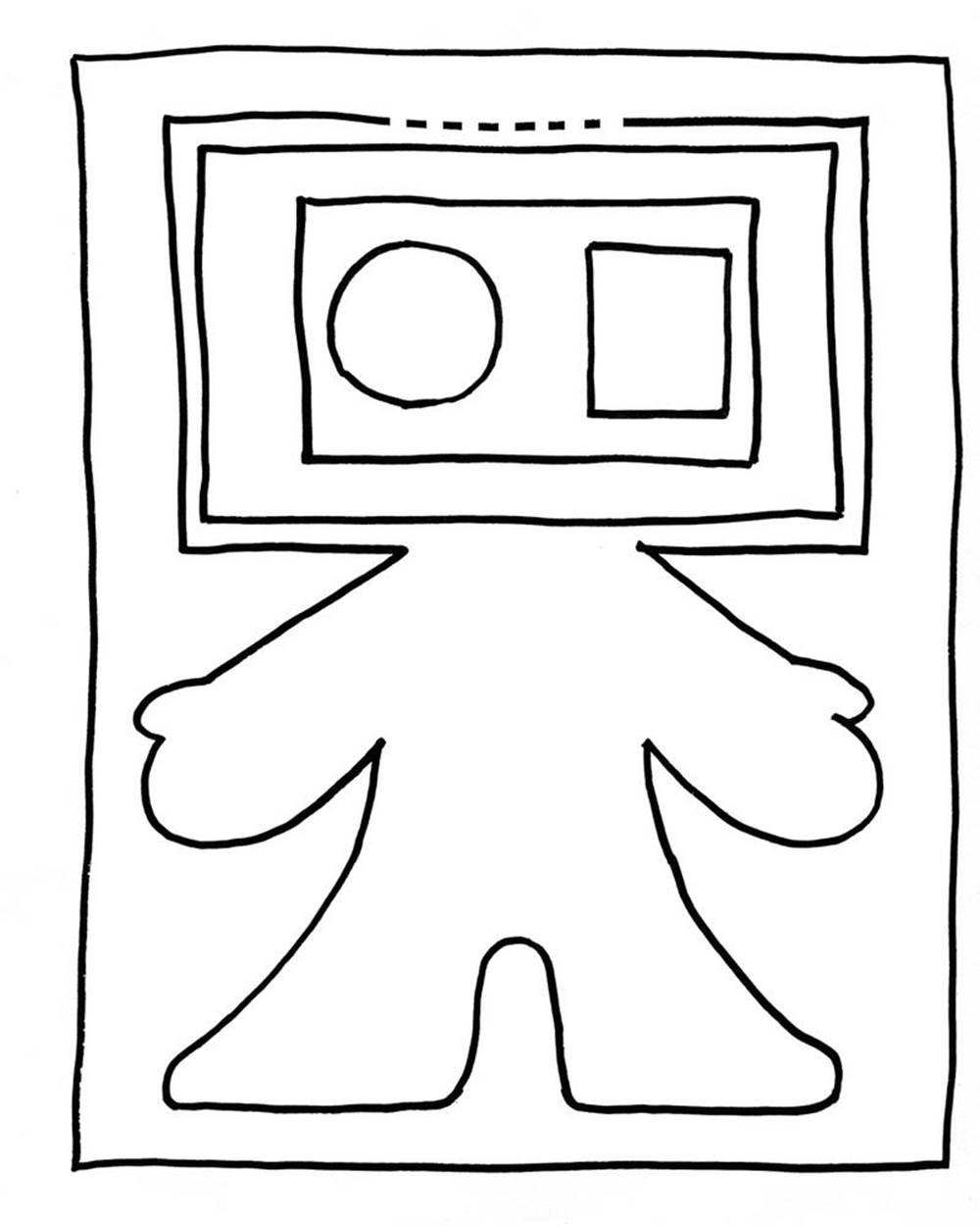
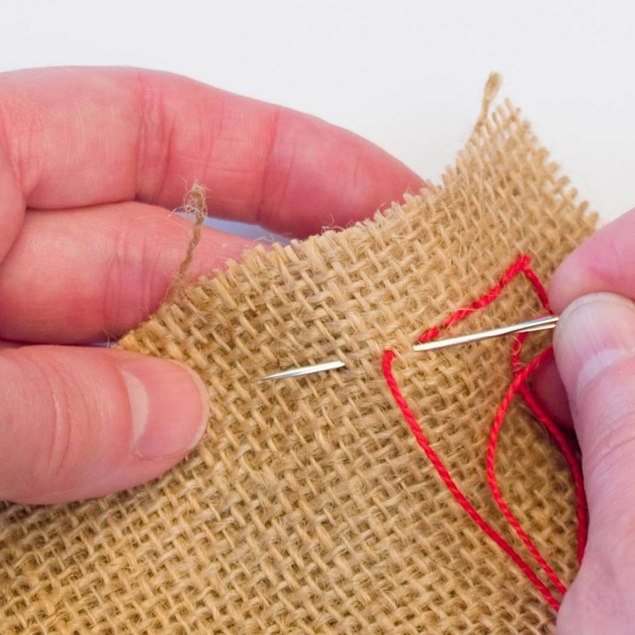
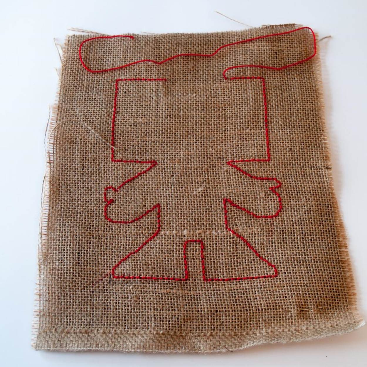
2. You will be sewing around the outline of the FiberBot body using the backstitch, starting on one side of the opening at the top of the head marked with a dotted line on the pattern. To do a backstitch, thread the largest needle you have with a piece of embroidery thread about 3 feet (1 m) long. (Do not separate the thread into strands.) Bring the needle through from the back to the front about 1/8 inch (3 mm) ahead of where you want to start. Go back to the starting point and push the needle through from front to back. Take one more stitch the same way to anchor the thread. Then come around once more, but this time push the needle up from back to front about 1/8 inch (3 mm) ahead of the end of the previous stitch. Then go back to the end of the previous stitch and push the needle through from front to back. Continue on with the backstitch around the entire body, stopping on the other side of the opening. Leave any excess thread hanging for now.
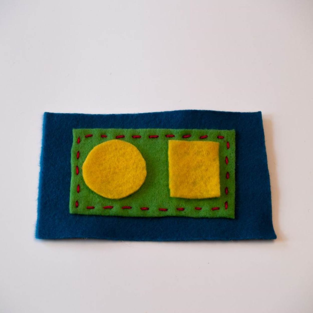
3. Take the felt and cut out two large rectangles, one medium rectangle, one small rectangle, and one circle, following the pattern. Center the medium rectangle on one of the large rectangles and sew them together using a running (in and out) stitch. Make a knot at the beginning and the end of your sewing to keep the thread from coming out. Trim any excess thread at the end.
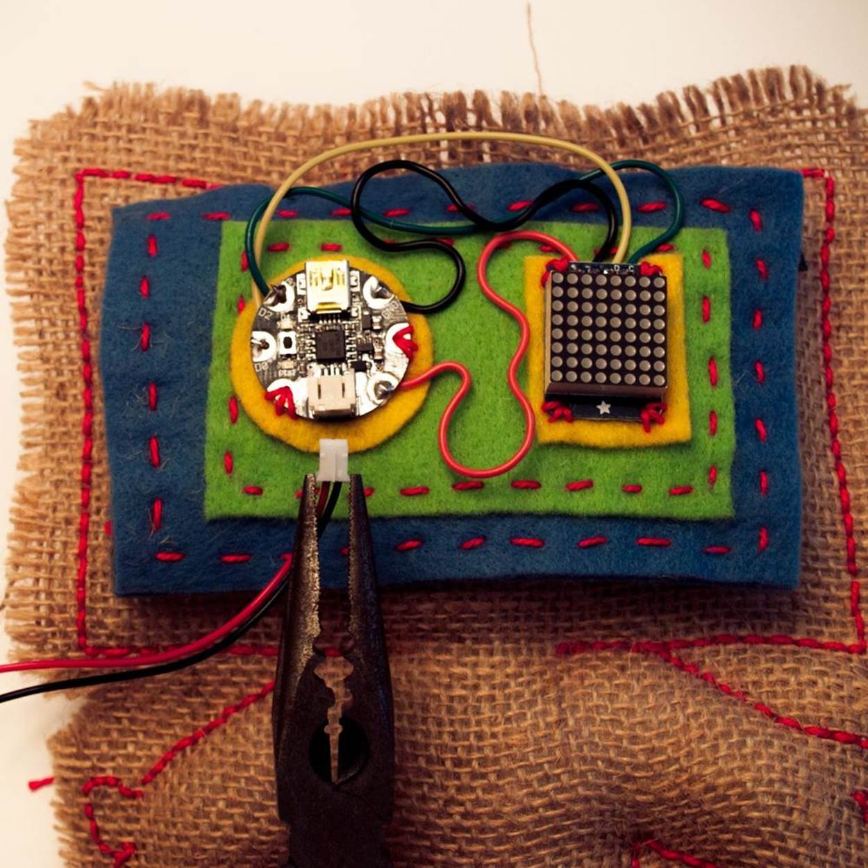
4. The Gemma and the LED Matrix go side by side on top of the medium rectangle, with the Gemma on the left. If the wires connecting them are stiff enough, curl them (gently!) into decorative waves to take up the slack. Be careful not to bend them too sharply, especially at the soldered ends, or they will break. Position the small felt rectangle under the LED Matrix. Using the large holes on the corners of the LED backpack, sew the device onto the felt, through all the layers, using three stitches in each hole. Knot the thread at the beginning and end to keep it in place. There are two holes available on the Gemma for sewing. Position the circular felt pad underneath the Gemma and sew it on through those two holes the same way as the LED Matrix.
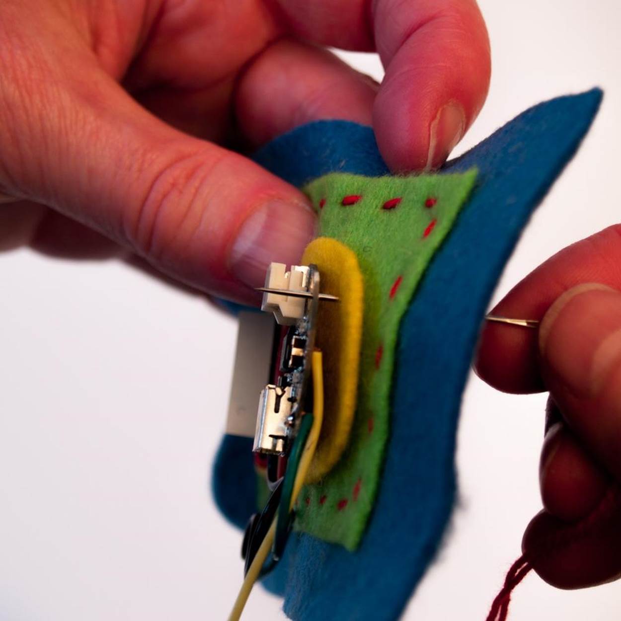
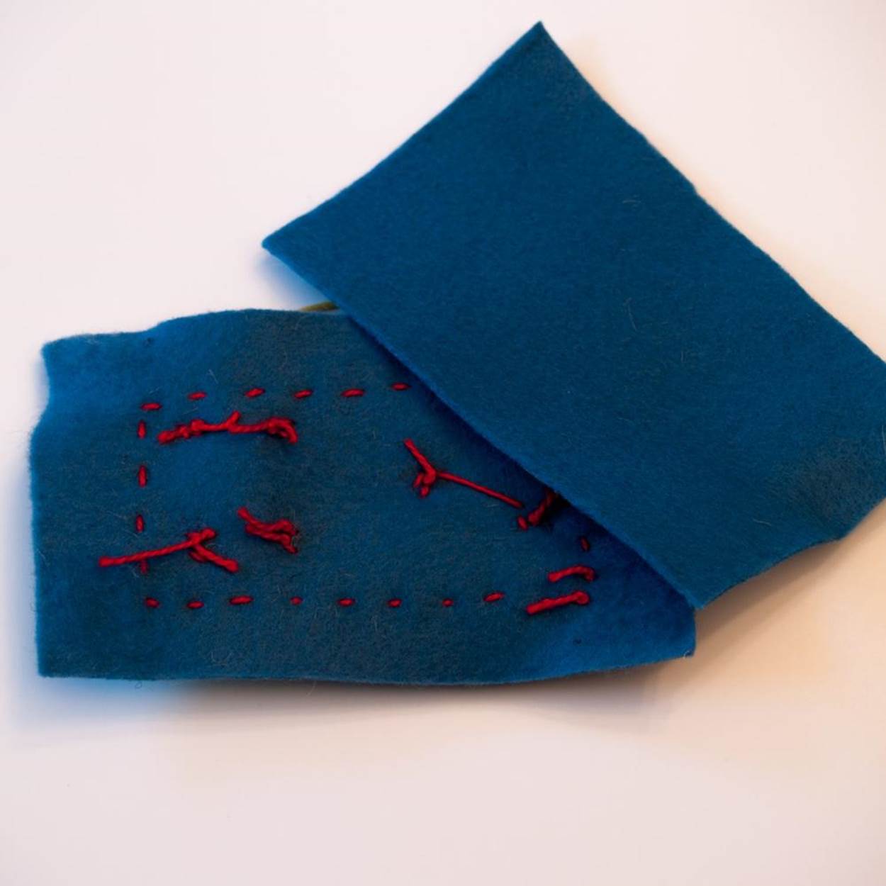
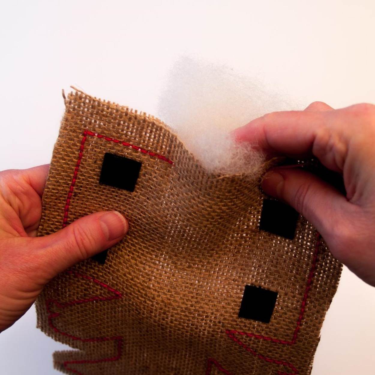
5. The second large felt rectangle is to hide all the stitching on the back of the first large felt rectangle. Attach four small peel-and-stick Velcro tabs onto the corners of the second felt piece, leaving room around the edges for stitching. Sew the felt pieces together, with the Velcro tabs on the outside. Attach the corresponding pieces of Velcro to the FiberBot’s burlap head, pressing to make a good seal. Connect the felt face to the FiberBot.
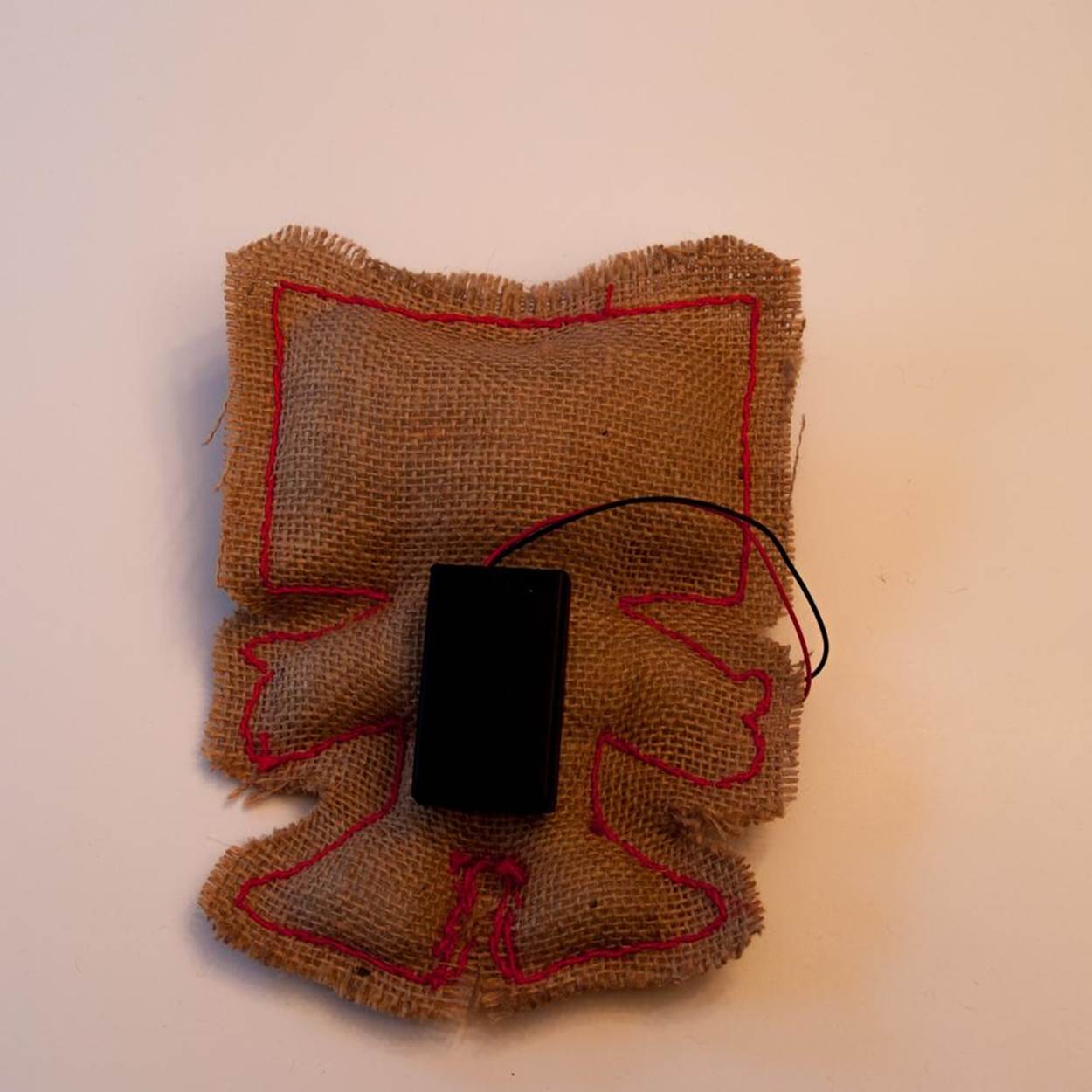
6. Plug the battery pack into the Gemma using the JST connector. Stick a piece of Velcro on the battery case opposite the side with the on/off switch. Stick the corresponding piece to the FiberBot’s back, pressing firmly. Now remove the face and the battery pack and set aside. If you have trouble unplugging the JST plug, use a pair of pliers to gently pull it out of the socket.
7. Insert the stuffing into the FiberBot through the opening at the top of the head. Use the eraser end of a pencil, a chopstick, or the handle of a wood spoon to get the stuffing into any corners you can’t reach with your fingers. Try to fill it loosely—just enough to give it a little three-dimensionality—since the burlap may fray and tear if stretched. When you’re satisfied, use the remaining thread to close up the hole with a backstitch.
8. Carefully trim around the outside of your stitching, leaving at least 1/2 inch (1 cm) of excess. You want a little fraying for a rough effect, but don’t trim too close to the stitching or the burlap will fall apart. Just take a small snip in tight places like around the arms and the legs, and don’t cut between the legs at all. If you do have fraying, you may be able to catch it with another row of stitching. Luckily, this style lends itself to a rough finish. Now reattach all the electronics, and your FiberBot is finished!
Step 5: Test Your Design
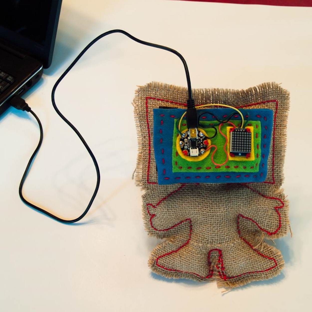
When your Gemma and LED backpack are all wired up, it’s time to try them out with the Arduino IDE and Adafruit programming. There are several steps involved, and you will have to download the necessary software from the Adafruit website onto your computer. Then you will upload the software from your computer to the Gemma via the USB cable. Here are the steps:
1. If you have a Windows computer, you first need to download a driver called USBtinyISP. (A driver is a small piece of software that tells the computer how to communicate with the hardware you are plugging in, in this case the Gemma.)
To install the driver:
o Go to the “Drivers” section of the Adafruit website for directions for Windows 7, 8, and XP.
o Plug your Gemma into a USB port on your computer using the Mini USB cable. The onboard green LED should light up, and the onboard red LED should start flashing.
o An installation wizard pop-up box should open up on your computer screen; tell it not to search the web for a driver, and it should install the driver on your hard drive.
If the driver doesn’t work, try one of the other versions you can find on the Adafruit page. My computer did not automatically open the installation wizard, but I was able to find the device and instruct the computer to manually install the driver folder. You may have to tell your computer to ignore a warning that the file isn’t safe; it is.
2. Next, you need to install the version of the Arduino IDE that works with Adafruit’s Gemma, Flora, and Trinket Arduino boards. If you already have a standard version of Arduino, there are directions to modify it yourself—but it’s easier to just install Adafruit’s customized version. Here’s how:
o Go to the Adafruit website for instructions and links.
o When you have downloaded the appropriate ZIP folder, move it where desired on your hard drive, and then extract all the files inside.
3. Find the Arduino IDE (it’s marked with a little teal Arduino symbol) in the directory where you stored the Arduino files. Click on it and a little pop-up window will open with an Arduino editing screen. Before you run your first sketch, or program, you need to adjust some settings. Click on Tools on the menu bar at the top of the Arduino window and then click on these:
o Under Board, select Adafruit Gemma 8MHz
o Under Programmer, select USBtinyISP
o Under Serial Port, select the number of the USB port you have plugged the Gemma into. (You may need to try a few to find the right one.)
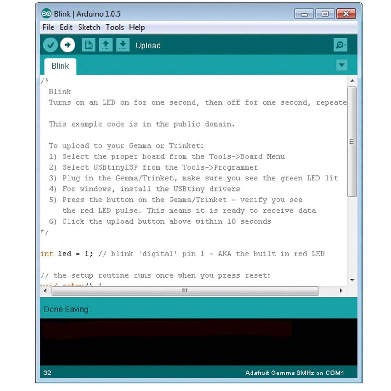
4. To test everything out, you will open and run a little a sketch, called Blink. It’s the “Hello World” for Arduino. Here’s how:
o Copy and paste the Blink sketch (below and at on the Arduino website, scroll down to the bottom of the page) into the white input screen in the Arduino pop-up window.
o Take the Gemma and press the reset button that sits between the red and green LEDs on the board. The red LED should shine dimly and then start flashing rapidly. That means the bootloader is ready to let you boot up a program.
o Click the Upload icon on the Arduino screen (the arrow that points to the right) and watch what happens. The code should start compiling (meaning Arduino is reading the program and translating it into digital code that the hardware can understand). If all goes well, the red LED on the Gemma should start blinking on and off in one second intervals (more slowly than it was flashing before).
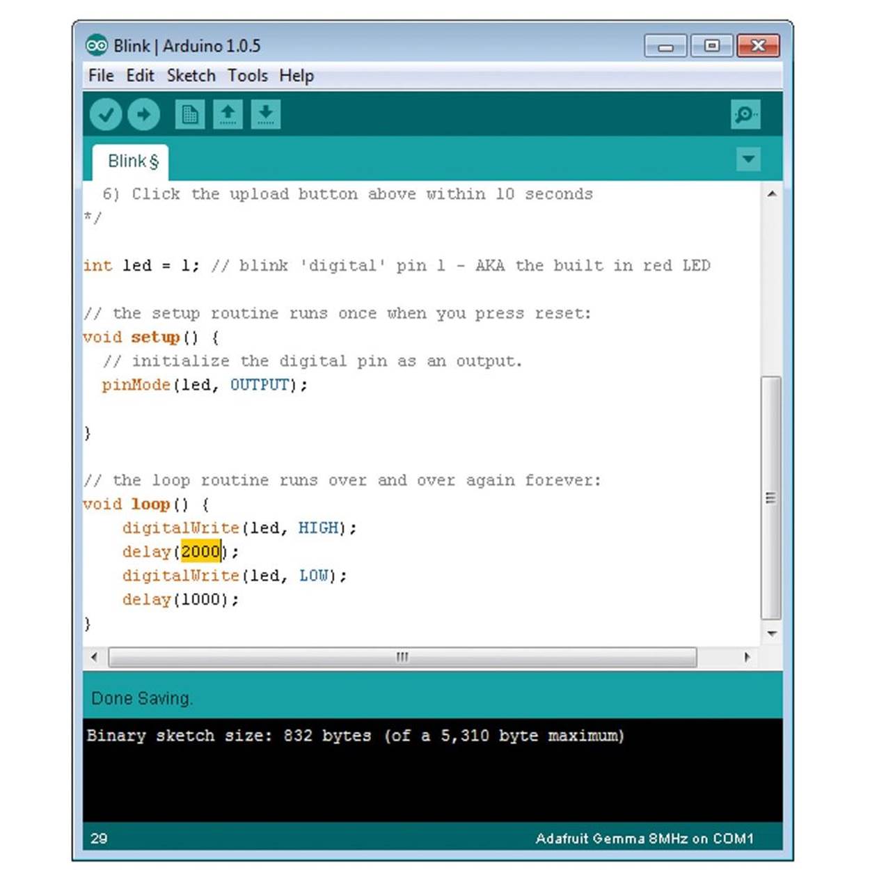
o You can play around with the code for the Blink sketch to see how it works. Look for the lines that say delay (1000); that command tells the Arduino device to turn the LED on or off for 1,000 thousandths of a second (or one second). If you change the numbers to 2,000, it will blink twice as slow. Change them to 500, and it will blink twice as fast. Don’t forget to push the reset button on Gemma before you click Upload on the Arduino screen every time.
5. Below the white input screen in the Arduino pop-up window, there is a black status area that tells you if your sketch is running correctly or has errors. If you see red text in that box, that means something’s wrong. The most common error message you are likely to get is avrdude: Error: Could not find USBtiny device (0x1781/0xc9f). That happens when you forget to press the reset button on the Gemma before you click Upload. Just try it again and the error message should go away. For other error messages, read through the directions again, and check the page “Setting Up with Arduino IDE” page for any updates. You can also head over to the Adafruit Customer Support Forum, where a live person will answer your questions relatively quickly. However, even with an error message the sketch may run correctly. For purposes of getting your Gemma and LED Matrix up and running, that may be good enough to move to the next step.
6. Once your Gemma is running the Blink sketch successfully, you need to get the LED Matrix involved. For that, you need to download a library, or bunch of related programs, called TinyWireM. Here’s how:
o Close any open Arduino windows.
o Go to the Adafruit website to find the link to the TinyWireM library and download it.
o Unzip the library file. It’s important to move it to the correct folder. In Windows, the Arduino IDE will automatically create a libraries folder in your Documents directory, under My Documents. If you need help finding the right folder, check out the Adafruit website for help.
7. Now you’re ready to run some animations on the LED Matrix. The sketches to run the LED Matrix are split into two pages. When you open the pages in the Arduino IDE, they will go in two separate tabs in the editing screen, like the tabs on an Internet browser. The first tab is the source code (Example 5-1). This can stay the same for every animation that you write. To load it, open the Arduino IDE and start a new sketch. Copy the source code below (or find it on the Gemma section of the Adafruit site) and paste it into the Arduino IDE editing screen. Click Save As in the File menu and give the source code a name (like “LEDMatrixSourceCode”), so you have a clean copy you can reuse to create new sketches.
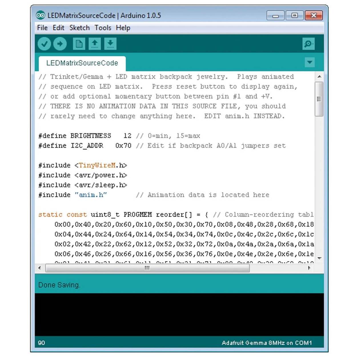
Example 5-1. Source code for Gemma—LED Matrix
// Trinket/Gemma + LED matrix backpack. Plays animated
// sequence on LED matrix. Press reset button to display again,
// or add optional momentary button between pin #1 and +V.
// THERE IS NO ANIMATION DATA IN THIS SOURCE FILE, you should
// rarely need to change anything here. EDIT anim.h INSTEAD.
#define BRIGHTNESS 12 // 0=min, 15=max
#define I2C_ADDR 0x70 // Edit if backpack A0/A1 jumpers set
#include <TinyWireM.h>
#include <avr/power.h>
#include <avr/sleep.h>
#include "anim.h" // Animation data is located here
static const uint8_t PROGMEM reorder[] = { // Column-reordering table
0x00,0x40,0x20,0x60,0x10,0x50,0x30,0x70,0x08,0x48,0x28,0x68,0x18,0x58,0x38,0x78,
0x04,0x44,0x24,0x64,0x14,0x54,0x34,0x74,0x0c,0x4c,0x2c,0x6c,0x1c,0x5c,0x3c,0x7c,
0x02,0x42,0x22,0x62,0x12,0x52,0x32,0x72,0x0a,0x4a,0x2a,0x6a,0x1a,0x5a,0x3a,0x7a,
0x06,0x46,0x26,0x66,0x16,0x56,0x36,0x76,0x0e,0x4e,0x2e,0x6e,0x1e,0x5e,0x3e,0x7e,
0x01,0x41,0x21,0x61,0x11,0x51,0x31,0x71,0x09,0x49,0x29,0x69,0x19,0x59,0x39,0x79,
0x05,0x45,0x25,0x65,0x15,0x55,0x35,0x75,0x0d,0x4d,0x2d,0x6d,0x1d,0x5d,0x3d,0x7d,
0x03,0x43,0x23,0x63,0x13,0x53,0x33,0x73,0x0b,0x4b,0x2b,0x6b,0x1b,0x5b,0x3b,0x7b,
0x07,0x47,0x27,0x67,0x17,0x57,0x37,0x77,0x0f,0x4f,0x2f,0x6f,0x1f,0x5f,0x3f,0x7f,
0x80,0xc0,0xa0,0xe0,0x90,0xd0,0xb0,0xf0,0x88,0xc8,0xa8,0xe8,0x98,0xd8,0xb8,0xf8,
0x84,0xc4,0xa4,0xe4,0x94,0xd4,0xb4,0xf4,0x8c,0xcc,0xac,0xec,0x9c,0xdc,0xbc,0xfc,
0x82,0xc2,0xa2,0xe2,0x92,0xd2,0xb2,0xf2,0x8a,0xca,0xaa,0xea,0x9a,0xda,0xba,0xfa,
0x86,0xc6,0xa6,0xe6,0x96,0xd6,0xb6,0xf6,0x8e,0xce,0xae,0xee,0x9e,0xde,0xbe,0xfe,
0x81,0xc1,0xa1,0xe1,0x91,0xd1,0xb1,0xf1,0x89,0xc9,0xa9,0xe9,0x99,0xd9,0xb9,0xf9,
0x85,0xc5,0xa5,0xe5,0x95,0xd5,0xb5,0xf5,0x8d,0xcd,0xad,0xed,0x9d,0xdd,0xbd,0xfd,
0x83,0xc3,0xa3,0xe3,0x93,0xd3,0xb3,0xf3,0x8b,0xcb,0xab,0xeb,0x9b,0xdb,0xbb,0xfb,
0x87,0xc7,0xa7,0xe7,0x97,0xd7,0xb7,0xf7,0x8f,0xcf,0xaf,0xef,0x9f,0xdf,0xbf,0xff };
void ledCmd(uint8_t x) { // Issue command to LED backback driver
TinyWireM.beginTransmission(I2C_ADDR);
TinyWireM.write(x);
TinyWireM.endTransmission();
}
void clear(void) { // Clear display buffer
TinyWireM.beginTransmission(I2C_ADDR);
for(uint8_t i=0; i<17; i++) TinyWireM.write(0);
TinyWireM.endTransmission();
}
void setup() {
power_timer1_disable(); // Disable unused peripherals
power_adc_disable(); // to save power
PCMSK |= _BV(PCINT1); // Set change mask for pin 1
TinyWireM.begin(); // I2C init
clear(); // Blank display
ledCmd(0x21); // Turn on oscillator
ledCmd(0xE0 | BRIGHTNESS); // Set brightness
ledCmd(0x81); // Display on, no blink
}
uint8_t rep = REPS;
void loop() {
for(int i=0; i<sizeof(anim); i) { // For each frame...
TinyWireM.beginTransmission(I2C_ADDR);
TinyWireM.write(0); // Start address
for(uint8_t j=0; j<8; j++) { // 8 rows...
TinyWireM.write(pgm_read_byte(&reorder[pgm_read_byte(&anim[i++])]));
TinyWireM.write(0);
}
TinyWireM.endTransmission();
delay(pgm_read_byte(&anim[i++]) * 10);
}
if(!--rep) { // If last cycle...
ledCmd(0x20); // LED matrix in standby mode
GIMSK = _BV(PCIE); // Enable pin change interrupt
power_all_disable(); // All peripherals off
set_sleep_mode(SLEEP_MODE_PWR_DOWN);
sleep_enable();
sei(); // Keep interrupts disabled
sleep_mode(); // Power down CPU (pin 1 will wake)
// Execution resumes here on wake.
GIMSK = 0; // Disable pin change interrupt
rep = REPS; // Reset animation counter
power_timer0_enable(); // Re-enable timer
power_usi_enable(); // Re-enable USI
TinyWireM.begin(); // Re-init I2C
clear(); // Blank display
ledCmd(0x21); // Re-enable matrix
}
}
ISR(PCINT0_vect) {} // Button tap
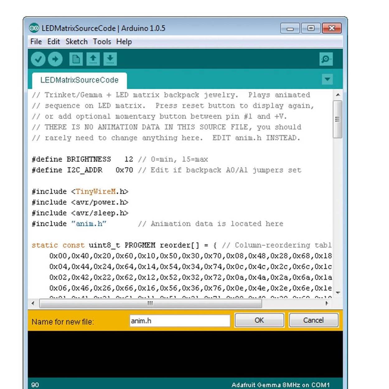
8. The second program you need to load into the Arduino IDE is the animation data itself. The EyeRoll animation below makes it look like your FiberBot is peering around with its one good eye. To create a new tab, look for a little arrow below the menu bar on the right side of the input screen. Click to open the drop-down menu and select New Tab. Name the new page anim.h. Then copy the EyeRoll code below (Example 5-2) and paste it into the new page. Click Save As in the File menu and give the sketch a name (like “MyEyeRollAnimation”). If you don’t already have a folder for your sketches, create one in the directory with the rest of your Arduino code and save this sketch there. Arduino will create a folder that contains the source code and the animation sketch.
Example 5-2. EyeRoll sketch
// EyeRoll Animation data for Gemma + LED matrix backpack.
#define REPS 3 // Number of times to repeat the animation loop (1-255)
const uint8_t PROGMEM anim[] = \{
B00000000, // frame 1
B00000000,
B00000000,
B00000000,
B00000000,
B00000000,
B11111111,
B01111110,
10, // 0.1 second delay
B00000000, // frame 2
B00000000,
B00000000,
B00000000,
B00000000,
B11111111,
B10000001,
B01111110,
10, // 0.1 second delay
B00000000, // frame 3
B00000000,
B00000000,
B00000000,
B11111111,
B10000001,
B10000001,
B01111110,
10, // 0.1 second delay
B00000000, // frame 4
B00000000,
B00000000,
B11111111,
B10011001,
B10000001,
B10000001,
B01111110,
10, // 0.1 second delay
B00000000, // frame 5
B00000000,
B11111111,
B10011001,
B10011001,
B10000001,
B10000001,
B01111110,
10, // 0.1 second delay
B00000000, // frame 6
B11111111,
B10011001,
B10011001,
B10011001,
B10000001,
B10000001,
B01111110,
10, // 0.1 second delay
B01111110, // frame 7
B10000001,
B10011001,
B10011001,
B10011001,
B10000001,
B10000001,
B01111110,
300, // 3 second delay
B01111110, // frame 8
B10000001,
B10001101,
B10001101,
B10001101,
B10000001,
B10000001,
B01111110,
25, // .25 second delay
B01111110, // frame 9
B10000001,
B10000111,
B10000111,
B10000111,
B10000001,
B10000001,
B01111110,
500, // 5 second delay
B01111110, // frame 10
B10001101,
B10001101,
B10001101,
B10000001,
B10000001,
B10000001,
B01111110,
10, // 0.1 second delay
B01111110, // frame 11
B10011001,
B10011001,
B10011001,
B10000001,
B10000001,
B10000001,
B01111110,
10, // 0.1 second delay
B01111110, // frame 12
B10000001,
B11100001,
B11100001,
B11100001,
B10000001,
B10000001,
B01111110,
500, // 5 second delay
B01111110, // frame 13
B10000001,
B10000001,
B10110001,
B10110001,
B10110001,
B10000001,
B01111110,
10, // 0.1 second delay
B01111110, // frame 14
B10000001,
B10000001,
B10000001,
B10011001,
B10011001,
B10011001,
B01111110,
10, // 0.1 second delay
B01111110, // frame 15
B10000001,
B10000001,
B10001101,
B10001101,
B10001101,
B10000001,
B01111110,
10, // 0.1 second delay
B01111110, // frame 16
B10000111,
B10000111,
B10000111,
B10000001,
B10000001,
B10000001,
B01111110,
100, // 1 second delay
B01111110, // frame 17
B10001101,
B10001101,
B10001101,
B10000001,
B10000001,
B10000001,
B01111110,
10, // 0.1 second delay
B01111110, // frame 18
B10000001,
B10011001,
B10011001,
B10011001,
B10000001,
B10000001,
B01111110,
300, // 3 second delay
B00000000, // frame 19
B11111111,
B10011001,
B10011001,
B10011001,
B10000001,
B10000001,
B01111110,
10, // 0.1 second delay
B00000000, // frame 20
B00000000,
B11111111,
B10011001,
B10011001,
B10000001,
B10000001,
B01111110,
10, // 0.1 second delay
B00000000, // frame 21
B00000000,
B00000000,
B11111111,
B10011001,
B10000001,
B10000001,
B01111110,
10, // 0.1 second delay
B00000000, // frame 22
B00000000,
B00000000,
B00000000,
B11111111,
B10000001,
B10000001,
B01111110,
10, // 0.1 second delay
B00000000, // frame 23
B00000000,
B00000000,
B00000000,
B00000000,
B11111111,
B10000001,
B01111110,
10, // 0.1 second delay
//rapid blink
B00000000, // frame 1
B00000000,
B00000000,
B00000000,
B00000000,
B00000000,
B11111111,
B01111110,
10, // 0.1 second delay
B00000000, // frame 2
B00000000,
B00000000,
B00000000,
B00000000,
B11111111,
B10000001,
B01111110,
10, // 0.1 second delay
B00000000, // frame 3
B00000000,
B00000000,
B00000000,
B11111111,
B10000001,
B10000001,
B01111110,
10, // 0.1 second delay
B00000000, // frame 4
B00000000,
B00000000,
B11111111,
B10011001,
B10000001,
B10000001,
B01111110,
10, // 0.1 second delay
B00000000, // frame 5
B00000000,
B11111111,
B10011001,
B10011001,
B10000001,
B10000001,
B01111110,
10, // 0.1 second delay
B00000000, // frame 6
B11111111,
B10011001,
B10011001,
B10011001,
B10000001,
B10000001,
B01111110,
10, // 0.1 second delay
B01111110, // frame 7
B10000001,
B10011001,
B10011001,
B10011001,
B10000001,
B10000001,
B01111110,
100, // 1 second delay
B01111110, // frame 7a
B10000001,
B10111101,
B10111101,
B10111101,
B10000001,
B10000001,
B01111110,
20, // 0.2 second delay
B01111110, // frame 7b
B10111101,
B11111111,
B11100111,
B11111111,
B10111101,
B10000001,
B01111110,
20, // 0.2 second delay
B01111110, // frame 7a
B10000001,
B10111101,
B10111101,
B10111101,
B10000001,
B10000001,
B01111110,
20, // 0.2 second delay
B01111110, // frame 7b
B10111101,
B11111111,
B11100111,
B11111111,
B10111101,
B10000001,
B01111110,
20, // 0.2 second delay
B01111110, // frame 7a
B10000001,
B10111101,
B10111101,
B10111101,
B10000001,
B10000001,
B01111110,
20, // 0.2 second delay
B01111110, // frame 7b
B10111101,
B11111111,
B11100111,
B11111111,
B10111101,
B10000001,
B01111110,
20, // 0.2 second delay
B01111110, // frame 7a
B10000001,
B10111101,
B10111101,
B10111101,
B10000001,
B10000001,
B01111110,
20, // 0.2 second delay
B01111110, // frame 7
B10000001,
B10011001,
B10011001,
B10011001,
B10000001,
B10000001,
B01111110,
100, // 1 second delay
B00000000, // frame 5
B00000000,
B11111111,
B10011001,
B10011001,
B10000001,
B10000001,
B01111110,
10, // 0.1 second delay
B00000000, // frame 4
B00000000,
B00000000,
B11111111,
B10011001,
B10000001,
B10000001,
B01111110,
10, // 0.1 second delay
B00000000, // frame 3
B00000000,
B00000000,
B00000000,
B11111111,
B10000001,
B10000001,
B01111110,
10, // 0.1 second delay
B00000000, // frame 2
B00000000,
B00000000,
B00000000,
B00000000,
B11111111,
B10000001,
B01111110,
10, // 0.1 second delay
B00000000, // frame 1
B00000000,
B00000000,
B00000000,
B00000000,
B00000000,
B11111111,
B01111110,
10, // 0.1 second delay
B00000000, // frame 2
B00000000,
B00000000,
B00000000,
B00000000,
B11111111,
B10000001,
B01111110,
10, // 0.1 second delay
B00000000, // frame 3
B00000000,
B00000000,
B00000000,
B11111111,
B10000001,
B10000001,
B01111110,
10, // 0.1 second delay
B00000000, // frame 4
B00000000,
B00000000,
B11111111,
B10011001,
B10000001,
B10000001,
B01111110,
10, // 0.1 second delay
B00000000, // frame 5
B00000000,
B11111111,
B10011001,
B10011001,
B10000001,
B10000001,
B01111110,
10, // 0.1 second delay
B00000000, // frame 6
B11111111,
B10011001,
B10011001,
B10011001,
B10000001,
B10000001,
B01111110,
10, // 0.1 second delay
B01111110, // frame 7
B10000001,
B10011001,
B10011001,
B10011001,
B10000001,
B10000001,
B01111110,
10, // 0.1 second delay
B00000000, // frame 5
B00000000,
B11111111,
B10011001,
B10011001,
B10000001,
B10000001,
B01111110,
10, // 0.1 second delay
B00000000, // frame 4
B00000000,
B00000000,
B11111111,
B10011001,
B10000001,
B10000001,
B01111110,
10, // 0.1 second delay
B00000000, // frame 3
B00000000,
B00000000,
B00000000,
B11111111,
B10000001,
B10000001,
B01111110,
10, // 0.1 second delay
B00000000, // frame 2
B00000000,
B00000000,
B00000000,
B00000000,
B11111111,
B10000001,
B01111110,
10, // 0.1 second delay
//end of sequence
B00000000, //frame 23
B00000000,
B00000000,
B00000000,
B00000000,
B00000000,
B11111111,
B01111110,
300, //3 second delay
};
9. Now to test the program. If the EyeRoll sketch isn’t already open, go into the folder where the two files you just created were saved. Double-click on the source code file (with the .ino suffix) to open both. Press the reset button on the Gemma, wait for the red LED to flash, then click Upload. After a few seconds, the EyeRoll animation should start to play on the LED Matrix. Does it work? Congratulations, you’re programming in Arduino! (If not, check Step 6 for troubleshooting tips.)

10. You now know how to set up a Gemma and LED Matrix. When you’re done, disconnect your FiberBot from the computer and run it off the batteries. If you haven’t already, insert three AAA batteries into the pack and plug it in. To run the animation, turn on the switch on the battery pack. To restart it when it’s done, just press the reset button on the Gemma itself. Enjoy your FiberBot, or skip ahead to Step 7 to find out how to create your own LED animation.
Step 6: Troubleshoot and Refine
If your hardware isn’t working, first make sure no connections are broken and no wires are touching and shorting out the circuit. Go over the steps above, to be sure everything is attached correctly.
If the software isn’t running the way it should, double-check to be sure you didn’t leave out any punctuation marks. Every curly bracket and semicolon is important! Also be sure your lines of animation code begin with a B, end with a comma, and that you have a delay time for each frame.
Step 7: Adaptations and Extensions
Want to try your own animation? Customizing the sketch is surprisingly easy. All you need to do is change the code on the anim.h page. The source code page stays the same. Be sure to save the entire sketch under a new name.
To see how to draw your own animation frames, take a look at the animation code itself. You’ll see that—like the 8×8 LED Matrix—each frame of the animation is written out in an 8 by 8 grid. Each LED pixel is represented by a one (indicating the light is on) or a zero (indicating the light is off). So by looking at each block of code, you can get an idea of what it is telling the LED Matrix to do. This is called a bitmap. (The text that comes after the // is documentation, notes from the programmer to explain what’s happening.) Here’s an example:
B00000000, // frame 5
B00000000,
B11111111,
B10011001,
B10011001,
B10000001,
B10000001,
B01111110,
10, // 0.10 second delay
As you can see, there are a few other little pieces of code you need to watch out for. Each line of code must start with a letter B and end with a comma. And after each block of eight lines representing the LED pixels is a ninth line that tells the Gemma how long that frame will last. In the example above, the number 10 followed by a comma means that frame will be displayed for a tenth (0.10) of a second. The delay time can range from 0 (no delay) to 255 (2.55 seconds). For longer delays, just repeat the same frames. According to Adafruit, the Gemma’s memory can store about 320 frames of animation.
You can use any design you like for your animated LED Matrix. You can make changes right in the Arduino IDE window, or copy the EyeBlink sketch into Notebook or a word processing program, modify it to your specifications, and paste it into the anim.h page. The source code page stays the same. Click Save As and give your new sketch a new name. Then upload it to Gemma to see how it runs. Have fun!