Introduction to 3D Game Programming with DirectX 12 (Computer Science) (2016)
|
Part 3 |
TOPICS |
In this part, we focus on applying Direct3D to implement several 3D applications, demonstrating techniques such as sky rendering, ambient occlusion, character animation, picking, environment mapping, normal mapping, and shadow mapping. A brief description of the chapters in this part follows.
Chapter 15, Building a First Person Camera and Dynamic Indexing: In this chapter, we show how to design a camera system that behaves more as you would expect in a first person game. We show how to control the camera via keyboard and mouse input. In addition, we introduce a new Direct3D 12 technique called dynamic indexing, where we can dynamically index an array of texture objects in a shader.
Chapter 16, Instancing and Frustum Culling: Instancing is a hardware supported technique that optimizes the drawing of the same geometry multiple times with different properties (say at different positions in the scene and with different colors). Frustum culling is an optimization technique where we discard an entire object from being submitted to the rendering pipeline if it lies completely outside the virtual camera’s field of view. We also show how to compute the bounding box and sphere of a mesh.
Chapter 17, Picking: This chapter shows how to determine the particular 3D object (or 3D primitive) that the user has selected with the mouse. Picking is often a necessity in 3D games and applications where the user interacts with the 3D world with the mouse.
Chapter 18, Cube Mapping: In this chapter, we show how to reflect environments onto arbitrary meshes with environment mapping; in addition, we use an environment map to texture a sky-sphere.
Chapter 19, Normal Mapping: This chapter shows how to get more detailed real-time lighting results by using normal maps, which are textures that store normal vectors. This gives surface normals at a finer granularity than per-vertex normals resulting in more realistic lighting.
Chapter 20, Shadow Mapping: Shadow mapping is a real-time shadowing technique, which shadows arbitrary geometry (it is not limited to planar shadows). In addition, we learn how projective texturing works.
Chapter 21, Ambient Occlusion: Lighting plays an important role in making our scenes look realistic. In this chapter, we improve the ambient term of our lighting equation by estimating how occluded a point in our scene is from incoming light.
Chapter 22, Quaternions: In this chapter, we study mathematical objects called quaternions. We show that unit quaternions represent rotations and can be interpolated in a simple way, thereby giving us a way to interpolate rotations. Once we can interpolate rotations, we can create 3D animations.
Chapter 23, Character Animation: This chapter covers the theory of character animation and show how to animate a typical human game character with a complex walking animation.
|
Chapter 15 |
BUILDING A FIRST |
In this chapter, we cover two separate short topics. First, we design a camera system that behaves more as you would expect in a first person game. This camera system will replace the orbiting camera system we have been using thus far in the demos. Second, we introduce a new Direct3D fig12 technique called dynamic indexing (new to shader model 5.1), where we can dynamically index an array of texture objects (Texture2D gDiffuseMap[n]). This is similar to how we indexed the special texture array object (Texture2DArray) in Chapter 12, but unlike Texture2DArray the textures in this array can be different sizes and formats, making it more flexible than Texture2DArrays.
Objectives:
1. To review the mathematics of the view space transformation.
2. To be able to identify the typical functionality of a first person camera.
3. To learn how to implement a first person camera.
4. To understand how to dynamically index into an array of textures.
15.1 VIEW TRANSFORM REVIEW
View space is the coordinate system attached to the camera as shown in Figure 15.1. The camera sits at the origin looking down the positive z-axis, the x-axis aims to the right of the camera, and the y-axis aims above the camera. Instead of describing our scene vertices relative to the world space, it is convenient for later stages of the rendering pipeline to describe them relative to the camera coordinate system. The change of coordinate transformation from world space to view space is called the view transform, and the corresponding matrix is called the view matrix.
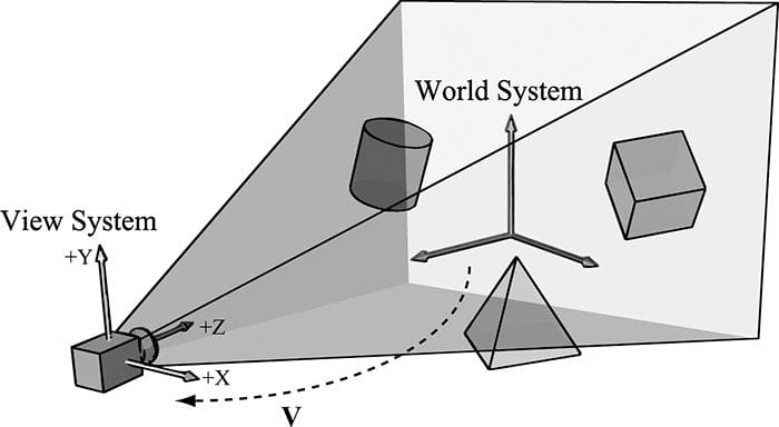
Figure 15.1. The camera coordinate system. Relative to its own coordinate system, the camera sits at the origin looking down the positive z-axis.
If QW = (Qx, Qy, Qz, 1), uW = (ux, uy, uz, 0), vW = (vx, vy, vz, 0), and wW = (wx, wy, wz, 0) describe, respectively, the origin, x-, y-, and z-axes of view space with homogeneous coordinates relative to world space, then we know from §3.4.3 that the change of coordinate matrix from view space to world space is:

However, this is not the transformation we want. We want the reverse transformation from world space to view space. But recall from §3.4.5 that reverse transformation is just given by the inverse. Thus W−1 transforms from world space to view space.
The world coordinate system and view coordinate system generally differ by position and orientation only, so it makes intuitive sense that W = RT (i.e., the world matrix can be decomposed into a rotation followed by a translation). This form makes the inverse easier to compute:

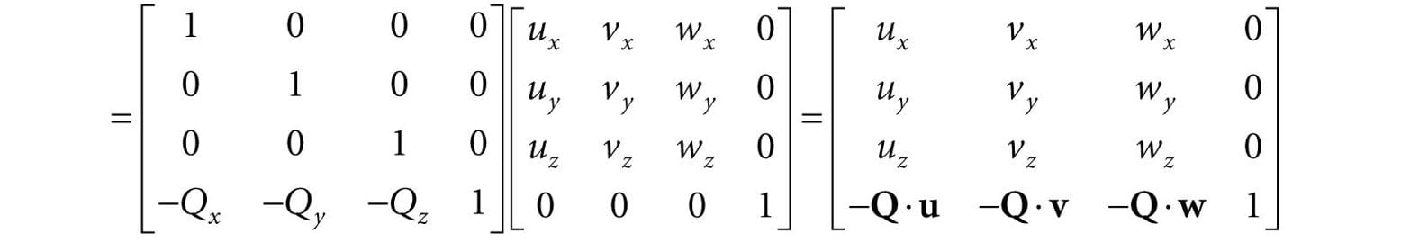
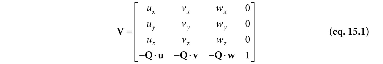
So the view matrix has the form:
As with all change-of-coordinate transformations, we are not moving anything in the scene. The coordinates change because we are using the camera space frame of reference instead of the world space frame of reference.
15.2 THE CAMERA CLASS
To encapsulate our camera related code, we define and implement a Camera class. The data of the camera class stores two key pieces of information. The position, right, up, and look vectors of the camera defining, respectively, the origin, x-axis, y-axis, and z-axis of the view space coordinate system in world coordinates, and the properties of the frustum. You can think of the lens of the camera as defining the frustum (its field of view and near and far planes). Most of the methods are trivial (e.g., simple access methods). See the comments below for an overview of the methods and data members. We review selected methods in the next section.
class Camera
{
public:
Camera();
˜Camera();
// Get/Set world camera position.
DirectX::XMVECTOR GetPosition()const;
DirectX::XMFLOAT3 GetPosition3f()const;
void SetPosition(float x, float y, float z);
void SetPosition(const DirectX::XMFLOAT3& v);
// Get camera basis vectors.
DirectX::XMVECTOR GetRight()const;
DirectX::XMFLOAT3 GetRight3f()const;
DirectX::XMVECTOR GetUp()const;
DirectX::XMFLOAT3 GetUp3f()const;
DirectX::XMVECTOR GetLook()const;
DirectX::XMFLOAT3 GetLook3f()const;
// Get frustum properties.
float GetNearZ()const;
float GetFarZ()const;
float GetAspect()const;
float GetFovY()const;
float GetFovX()const;
// Get near and far plane dimensions in view space coordinates.
float GetNearWindowWidth()const;
float GetNearWindowHeight()const;
float GetFarWindowWidth()const;
float GetFarWindowHeight()const;
// Set frustum.
void SetLens(float fovY, float aspect, float zn, float zf);
// Define camera space via LookAt parameters.
void LookAt(DirectX::FXMVECTOR pos,
DirectX::FXMVECTOR target,
DirectX::FXMVECTOR worldUp);
void LookAt(const DirectX::XMFLOAT3& pos,
const DirectX::XMFLOAT3& target,
const DirectX::XMFLOAT3& up);
// Get View/Proj matrices.
DirectX::XMMATRIX GetView()const;
DirectX::XMMATRIX GetProj()const;
DirectX::XMFLOAT4X4 GetView4x4f()const;
DirectX::XMFLOAT4X4 GetProj4x4f()const;
// Strafe/Walk the camera a distance d.
void Strafe(float d);
void Walk(float d);
// Rotate the camera.
void Pitch(float angle);
void RotateY(float angle);
// After modifying camera position/orientation, call to rebuild the view matrix.
void UpdateViewMatrix();
private:
// Camera coordinate system with coordinates relative to world space.
DirectX::XMFLOAT3 mPosition = { 0.0f, 0.0f, 0.0f };
DirectX::XMFLOAT3 mRight = { 1.0f, 0.0f, 0.0f };
DirectX::XMFLOAT3 mUp = { 0.0f, 1.0f, 0.0f };
DirectX::XMFLOAT3 mLook = { 0.0f, 0.0f, 1.0f };
// Cache frustum properties.
float mNearZ = 0.0f;
float mFarZ = 0.0f;
float mAspect = 0.0f;
float mFovY = 0.0f;
float mNearWindowHeight = 0.0f;
float mFarWindowHeight = 0.0f;
bool mViewDirty = true;
// Cache View/Proj matrices.
DirectX::XMFLOAT4X4 mView = MathHelper::Identity4x4();
DirectX::XMFLOAT4X4 mProj = MathHelper::Identity4x4();
};
|
|
The Camera.h/Camera.cpp files are in the Common directory. |

15.3 SELECTED METHOD IMPLEMENTATIONS
Many of the camera class methods are trivial get/set methods that we will omit here. However, we will review a few of the important ones in this section.
15.3.1 XMVECTOR Return Variations
First, we want to remark that we provide XMVECTOR return variations for many of the “get” methods; this is just for convenience so that the client code does not need to convert if they need an XMVECTOR:
XMVECTOR Camera::GetPosition()const
{
return XMLoadFloat3(&mPosition);
}
XMFLOAT3 Camera::GetPosition3f()const
{
return mPosition;
}
15.3.2 SetLens
We can think of the frustum as the lens of our camera, for it controls our view of view. We cache the frustum properties and build the projection matrix is the SetLens method:
void Camera::SetLens(float fovY, float aspect, float zn, float zf)
{
// cache properties
mFovY = fovY;
mAspect = aspect;
mNearZ = zn;
mFarZ = zf;
mNearWindowHeight = 2.0f * mNearZ * tanf( 0.5f*mFovY );
mFarWindowHeight = 2.0f * mFarZ * tanf( 0.5f*mFovY );
XMMATRIX P = XMMatrixPerspectiveFovLH(mFovY, mAspect, mNearZ, mFarZ);
XMStoreFloat4x4(&mProj, P);
}
15.3.3 Derived Frustum Info
As we just saw, we cache the vertical field of view angle, but additionally provide a method that derives the horizontal field of view angle. Moreover, we provide methods to return the width and height of the frustum at the near and far planes, which are sometimes useful to know. The implementations of these methods are just trigonometry, and if you have trouble following the equations, then review §5.6.3:
float Camera::GetFovX()const
{
float halfWidth = 0.5f*GetNearWindowWidth();
return 2.0f*atan(halfWidth / mNearZ);
}
float Camera::GetNearWindowWidth()const
{
return mAspect * mNearWindowHeight;
}
float Camera::GetNearWindowHeight()const
{
return mNearWindowHeight;
}
float Camera::GetFarWindowWidth()const
{
return mAspect * mFarWindowHeight;
}
float Camera::GetFarWindowHeight()const
{
return mFarWindowHeight;
}
15.3.4 Transforming the Camera
For a first person camera, ignoring collision detection, we want to be able to:
1. Move the camera along its look vector to move forwards and backwards. This can be implemented by translating the camera position along its look vector.
2. Move the camera along its right vector to strafe right and left. This can be implemented by translating the camera position along its right vector.
3. Rotate the camera around its right vector to look up and down. This can be implemented by rotating the camera’s look and up vectors around its right vector using the XMMatrixRotationAxis function.
4. Rotate the camera around the world’s y-axis (assuming the y-axis corresponds to the world’s “up” direction) vector to look right and left. This can be implemented by rotating all the basis vectors around the world’s y-axis using the XMMatrixRotationY function.
void Camera::Walk(float d)
{
// mPosition += d*mLook
XMVECTOR s = XMVectorReplicate(d);
XMVECTOR l = XMLoadFloat3(&mLook);
XMVECTOR p = XMLoadFloat3(&mPosition);
XMStoreFloat3(&mPosition, XMVectorMultiplyAdd(s, l, p));}
void Camera::Strafe(float d)
{
// mPosition += d*mRight
XMVECTOR s = XMVectorReplicate(d);
XMVECTOR r = XMLoadFloat3(&mRight);
XMVECTOR p = XMLoadFloat3(&mPosition);
XMStoreFloat3(&mPosition, XMVectorMultiplyAdd(s, r, p));
}
void Camera::Pitch(float angle)
{
// Rotate up and look vector about the right vector.
XMMATRIX R = XMMatrixRotationAxis(XMLoadFloat3(&mRight), angle);
XMStoreFloat3(&mUp, XMVector3TransformNormal(XMLoadFloat3(&mUp), R));
XMStoreFloat3(&mLook, XMVector3TransformNormal(XMLoadFloat3(&mLook), R));
}
void Camera::RotateY(float angle)
{
// Rotate the basis vectors about the world y-axis.
XMMATRIX R = XMMatrixRotationY(angle);
XMStoreFloat3(&mRight, XMVector3TransformNormal(XMLoadFloat3(&mRight), R));
XMStoreFloat3(&mUp, XMVector3TransformNormal(XMLoadFloat3(&mUp), R));
XMStoreFloat3(&mLook, XMVector3TransformNormal(XMLoadFloat3(&mLook), R));
}
15.3.5 Building the View Matrix
The first part of the UpdateViewMatrix method reorthonormalizes the camera’s right, up, and look vectors. That is to say, it makes sure they are mutually orthogonal to each other and unit length. This is necessary because after several rotations, numerical errors can accumulate and cause these vectors to become non-orthonormal. When this happens, the vectors no longer represent a rectangular coordinate system, but a skewed coordinate system, which is not what we want. The second part of this method just plugs the camera vectors into Equation 15.1 to compute the view transformation matrix.
void Camera::UpdateViewMatrix()
{
if(mViewDirty)
{
XMVECTOR R = XMLoadFloat3(&mRight);
XMVECTOR U = XMLoadFloat3(&mUp);
XMVECTOR L = XMLoadFloat3(&mLook);
XMVECTOR P = XMLoadFloat3(&mPosition);
// Keep camera’s axes orthogonal to each other and of unit length.
L = XMVector3Normalize(L);
U = XMVector3Normalize(XMVector3Cross(L, R));
// U, L already ortho-normal, so no need to normalize cross product.
R = XMVector3Cross(U, L);
// Fill in the view matrix entries.
float x = -XMVectorGetX(XMVector3Dot(P, R));
float y = -XMVectorGetX(XMVector3Dot(P, U));
float z = -XMVectorGetX(XMVector3Dot(P, L));
XMStoreFloat3(&mRight, R);
XMStoreFloat3(&mUp, U);
XMStoreFloat3(&mLook, L);
mView(0, 0) = mRight.x;
mView(1, 0) = mRight.y;
mView(2, 0) = mRight.z;
mView(3, 0) = x;
mView(0, 1) = mUp.x;
mView(1, 1) = mUp.y;
mView(2, 1) = mUp.z;
mView(3, 1) = y;
mView(0, 2) = mLook.x;
mView(1, 2) = mLook.y;
mView(2, 2) = mLook.z;
mView(3, 2) = z;
mView(0, 3) = 0.0f;
mView(1, 3) = 0.0f;
mView(2, 3) = 0.0f;
mView(3, 3) = 1.0f;
mViewDirty = false;
}
}
15.4 CAMERA DEMO COMMENTS
We can now remove all the old variables from our application class that were related to the orbital camera system such as mPhi, mTheta, mRadius, mView, and mProj. We will add a member variable:
Camera mCam;
When the window is resized, we know longer rebuild the projection matrix explicitly, and instead delegate the work to the Camera class with SetLens:
void CameraApp::OnResize()
{
D3DApp::OnResize();
mCamera.SetLens(0.25f*MathHelper::Pi, AspectRatio(), 1.0f, 1000.0f);
}
In the UpdateScene method, we handle keyboard input to move the camera:
void CameraApp::UpdateScene(float dt)
{
if( GetAsyncKeyState(‘W’) & 0x8000 )
mCamera.Walk(10.0f*dt);
if( GetAsyncKeyState(‘S’) & 0x8000 )
mCamera.Walk(-10.0f*dt);
if( GetAsyncKeyState(‘A’) & 0x8000 )
mCamera.Strafe(-10.0f*dt);
if( GetAsyncKeyState(‘D’) & 0x8000 )
mCamera.Strafe(10.0f*dt);
In the OnMouseMove method, we rotate the camera’s look direction:
void CameraAndDynamicIndexingApp::OnMouseMove(WPARAM btnState, int x, int y)
{
if( (btnState & MK_LBUTTON) != 0 )
{
// Make each pixel correspond to a quarter of a degree.
float dx = XMConvertToRadians(
0.25f*static_cast<float>(x - mLastMousePos.x));
float dy = XMConvertToRadians(
0.25f*static_cast<float>(y - mLastMousePos.y));
mCamera.Pitch(dy);
mCamera.RotateY(dx);
}
mLastMousePos.x = x;
mLastMousePos.y = y;
}
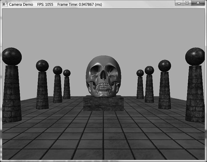
Figure 15.2. Screenshot of the camera demo. Use the ‘W’, ‘S’, ‘A’, and ‘D’ keys to move forward, backward, strafe left, and strafe right, respectively. Hold the left mouse button down and move the mouse to “look” in different directions.
Finally, for rendering, the view and projection matrices can be accessed from the camera instance:
mCamera.UpdateViewMatrix();
XMMATRIX view = mCamera.View();
XMMATRIX proj = mCamera.Proj();
15.5 DYNAMIC INDEXING
The idea of dynamic indexing is relatively straightforward. We dynamically index into an array of resources in a shader program; in this demo, the resources will be an array of textures. The index can be specified in various ways:
1. The index can be an element in a constant buffer.
2. The index can be a system ID like SV_PrimitiveID, SV_VertexID, SV_DispatchThreadID, or SV_InstanceID.
3. The index can be the result of come calculation.
4. The index can come from a texture.
5. The index can come from a component of the vertex structure.
The following shader syntax declares a texture array of 4 elements and shows how we can index into the texture array where the index comes from a constant buffer:
cbuffer cbPerDrawIndex : register(b0)
{
int gDiffuseTexIndex;
};
Texture2D gDiffuseMap[4] : register(t0);
float4 texValue = gDiffuseMap[gDiffuseTexIndex].Sample(
gsamLinearWrap, pin.TexC);
For this demo, our goal is the following: we want to minimize the number of descriptors we set on a per render-item basis. Right now we set the object constant buffer, the material constant buffer, and the diffuse texture map SRV on a per render-item basis. Minimizing the number of descriptors we need to set will make our root signature smaller, which means less overhead per draw call; moreover, this technique of dynamic indexing will prove especially useful with instancing (the topic of the next chapter). Our strategy is as follows:
1. Create a structured buffer that stores all of the material data. That is, instead of storing our material data in constant buffers, we will store it in a structured buffer. A structured buffer can be indexed in a shader program. This structured buffer will be bound to the rendering pipeline once per frame making all materials visible to the shader programs.
2. Add a MaterialIndex field to our object constant buffer to specify the index of the material to use for this draw call. In our shader programs, we use this to index into the material structured buffer.
3. Bind all of the texture SRV descriptors used in the scene once per frame, instead of binding one texture SRV per render-item.
4. Add a DiffuseMapIndex field to the material data that specifies the texture map associated with the material. We use this to index into the array of textures we bound to the pipeline in the previous step.
With this setup, we only need to set a per object constant buffer for each render-item. Once we have that, we use the MaterialIndex to fetch the material to use for the draw call, and from that we use the DiffuseMapIndex to fetch the texture to use for the draw call.
|
|
Recall that a structured buffer is just an array of data of some type that can live in GPU memory and be accessed by shader programs. Because we still need to be able to update materials on the fly, we use an upload buffer rather than a default buffer. The material structured buffer replaces our material constant buffer in the frame resources class and is created like so: |
struct MaterialData
{
DirectX::XMFLOAT4 DiffuseAlbedo = { 1.0f, 1.0f, 1.0f, 1.0f };
DirectX::XMFLOAT3 FresnelR0 = { 0.01f, 0.01f, 0.01f };
float Roughness = 64.0f;
// Used in texture mapping.
DirectX::XMFLOAT4X4 MatTransform = MathHelper::Identity4x4();
UINT DiffuseMapIndex = 0;
UINT MaterialPad0;
UINT MaterialPad1;
UINT MaterialPad2;
};
MaterialBuffer = std::make_unique<UploadBuffer<MaterialData>>(
device, materialCount, false);
|
Other than that, the code for the material structured buffer is not much different from the code with the material constant buffer. |
We update the root signature based on the new data the shader expects as input:
CD3DX12_DESCRIPTOR_RANGE texTable;
texTable.Init(D3D12_DESCRIPTOR_RANGE_TYPE_SRV, 4, 0, 0);
// Root parameter can be a table, root descriptor or root constants.
CD3DX12_ROOT_PARAMETER slotRootParameter[4];
// Perfomance TIP: Order from most frequent to least frequent.
slotRootParameter[0].InitAsConstantBufferView(0);
slotRootParameter[1].InitAsConstantBufferView(1);
slotRootParameter[2].InitAsShaderResourceView(0, 1);
slotRootParameter[3].InitAsDescriptorTable(1, &texTable, D3D12_SHADER_VISIBILITY_PIXEL);
auto staticSamplers = GetStaticSamplers();
// A root signature is an array of root parameters.
CD3DX12_ROOT_SIGNATURE_DESC rootSigDesc(4, slotRootParameter,
(UINT)staticSamplers.size(), staticSamplers.data(),
D3D12_ROOT_SIGNATURE_FLAG_ALLOW_INPUT_ASSEMBLER_INPUT_LAYOUT);
Now, before we draw any render-items, we can bind all of our materials and texture SRVs once per frame rather than per-render-item, and then each render-item just sets the object constant buffer:
void CameraAndDynamicIndexingApp::Draw(const GameTimer& gt)
{
…
auto passCB = mCurrFrameResource->PassCB->Resource();
mCommandList->SetGraphicsRootConstantBufferView(1, passCB->GetGPUVirtualAddress());
// Bind all the materials used in this scene. For structured buffers,
// we can bypass the heap and set as a root descriptor.
auto matBuffer = mCurrFrameResource->MaterialBuffer->Resource();
mCommandList->SetGraphicsRootShaderResourceView(2,
matBuffer->GetGPUVirtualAddress());
// Bind all the textures used in this scene. Observe
// that we only have to specify the first descriptor in the table.
// The root signature knows how many descriptors are expected in the table.
mCommandList->SetGraphicsRootDescriptorTable(3,
mSrvDescriptorHeap->GetGPUDescriptorHandleForHeapStart());
DrawRenderItems(mCommandList.Get(), mOpaqueRitems);
…
}
void CameraAndDynamicIndexingApp::DrawRenderItems(
ID3D12GraphicsCommandList* cmdList,
const std::vector<RenderItem*>& ritems)
{
…
// For each render item…
for(size_t i = 0; i < ritems.size(); ++i)
{
auto ri = ritems[i];
…
cmdList->SetGraphicsRootConstantBufferView(0, objCBAddress);
cmdList->DrawIndexedInstanced(ri->IndexCount, 1,
ri->StartIndexLocation, ri->BaseVertexLocation, 0);
}
}
We note that the ObjectConstants structure has been updated to have a MaterialIndex. The value you set for this is the same index you would have used to offset into the material constant buffer:
// UpdateObjectCBs…
ObjectConstants objConstants;
XMStoreFloat4x4(&objConstants.World, XMMatrixTranspose(world));
XMStoreFloat4x4(&objConstants.TexTransform, XMMatrixTranspose(texTransform));
objConstants.MaterialIndex = e->Mat->MatCBIndex;
The modified shader code demonstrating dynamic indexing is included below with relevant sections bolded:
// Include structures and functions for lighting.
#include “LightingUtil.hlsl”
struct MaterialData
{
float4 DiffuseAlbedo;
float3 FresnelR0;
float Roughness;
float4x4 MatTransform;
uint DiffuseMapIndex;
uint MatPad0;
uint MatPad1;
uint MatPad2;
};
// An array of textures, which is only supported in shader model 5.1+. Unlike
// Texture2DArray, the textures in this array can be different sizes and
// formats, making it more flexible than texture arrays.
Texture2D gDiffuseMap[4] : register(t0);
// Put in space1, so the texture array does not overlap with these resources.
// The texture array will occupy registers t0, t1, …, t3 in space0.
StructuredBuffer<MaterialData> gMaterialData : register(t0, space1);
SamplerState gsamPointWrap : register(s0);
SamplerState gsamPointClamp : register(s1);
SamplerState gsamLinearWrap : register(s2);
SamplerState gsamLinearClamp : register(s3);
SamplerState gsamAnisotropicWrap : register(s4);
SamplerState gsamAnisotropicClamp : register(s5);
// Constant data that varies per frame.
cbuffer cbPerObject : register(b0)
{
float4x4 gWorld;
float4x4 gTexTransform;
uint gMaterialIndex;
uint gObjPad0;
uint gObjPad1;
uint gObjPad2;
};
// Constant data that varies per material.
cbuffer cbPass : register(b1)
{
float4x4 gView;
float4x4 gInvView;
float4x4 gProj;
float4x4 gInvProj;
float4x4 gViewProj;
float4x4 gInvViewProj;
float3 gEyePosW;
float cbPerObjectPad1;
float2 gRenderTargetSize;
float2 gInvRenderTargetSize;
float gNearZ;
float gFarZ;
float gTotalTime;
float gDeltaTime;
float4 gAmbientLight;
// Indices [0, NUM_DIR_LIGHTS) are directional lights;
// indices [NUM_DIR_LIGHTS, NUM_DIR_LIGHTS+NUM_POINT_LIGHTS) are point lights;
// indices [NUM_DIR_LIGHTS+NUM_POINT_LIGHTS,
// NUM_DIR_LIGHTS+NUM_POINT_LIGHT+NUM_SPOT_LIGHTS)
// are spot lights for a maximum of MaxLights per object.
Light gLights[MaxLights];
};
struct VertexIn
{
float3 PosL : POSITION;
float3 NormalL : NORMAL;
float2 TexC : TEXCOORD;
};
struct VertexOut
{
float4 PosH : SV_POSITION;
float3 PosW : POSITION;
float3 NormalW : NORMAL;
float2 TexC : TEXCOORD;
};
VertexOut VS(VertexIn vin)
{
VertexOut vout = (VertexOut)0.0f;
// Fetch the material data.
MaterialData matData = gMaterialData[gMaterialIndex];
// Transform to world space.
float4 posW = mul(float4(vin.PosL, 1.0f), gWorld);
vout.PosW = posW.xyz;
// Assumes nonuniform scaling; otherwise, need to use inverse-transpose
// of world matrix.
vout.NormalW = mul(vin.NormalL, (float3x3)gWorld);
// Transform to homogeneous clip space.
vout.PosH = mul(posW, gViewProj);
// Output vertex attributes for interpolation across triangle.
float4 texC = mul(float4(vin.TexC, 0.0f, 1.0f), gTexTransform);
vout.TexC = mul(texC, matData.MatTransform).xy;
return vout;
}
float4 PS(VertexOut pin) : SV_Target
{
// Fetch the material data.
MaterialData matData = gMaterialData[gMaterialIndex];
float4 diffuseAlbedo = matData.DiffuseAlbedo;
float3 fresnelR0 = matData.FresnelR0;
float roughness = matData.Roughness;
uint diffuseTexIndex = matData.DiffuseMapIndex;
// Dynamically look up the texture in the array.
diffuseAlbedo *= gDiffuseMap[diffuseTexIndex].Sample(gsamLinearWrap, pin.TexC);
// Interpolating normal can unnormalize it, so renormalize it.
pin.NormalW = normalize(pin.NormalW);
// Vector from point being lit to eye.
float3 toEyeW = normalize(gEyePosW - pin.PosW);
// Light terms.
float4 ambient = gAmbientLight*diffuseAlbedo;
Material mat = { diffuseAlbedo, fresnelR0, roughness };
float4 directLight = ComputeDirectLighting(gLights, mat, pin.PosW, pin.NormalW, toEyeW);
float4 litColor = ambient + directLight;
// Common convention to take alpha from diffuse albedo.
litColor.a = diffuseAlbedo.a;
return litColor;
}
|
|
The above shader code demonstrated writing an explicit register space: StructuredBuffer<MaterialData> gMaterialData : register(t0, space1);
Texture2D gDiffuseMap : register(t0, space0); Texture2D gNormalMap : register(t0, space1); Texture2D gShadowMap : register(t0, space2);
Texture2D gDiffuseMap[4] : register(t0);
// Put in space1, so the texture array does not overlap with these // resources. // The texture array will occupy registers t0, t1, …, t3 in space0. StructuredBuffer<MaterialData> gMaterialData : register(t0, space1); |
To conclude this section, three additional uses of dynamic indexing are given:
1. Merging nearby meshes with different textures into a single render-item so that they can be drawn with one draw call. The meshes could store the texture/material to use as an attribute in the vertex structure.
2. Multitexturing in a single rendering-pass where the textures have different sizes and formats.
3. Instancing render-items with different textures and materials using the SV_InstanceID value as an index. We will see an example of this in the next chapter.
15.6 SUMMARY
1. We define the camera coordinate system by specifying its position and orientation. The position is specified by a position vector relative to the world coordinate system, and the orientation is specified by three orthonormal vectors relative to the world coordinate system: a right, up, and look vector. Moving the camera amounts to moving the camera coordinate system relative to the world coordinate system.
2. We included projection related quantities in the camera class, as the perspective projection matrix can be thought of as the “lens” of the camera by controlling the field of view, and near and far planes.
3. Moving forward and backwards can be implemented simply by translating the camera position along its look vector. Strafing right and left can be implemented simply by translating the camera position along its right vector. Looking up and down can be achieved by rotating the camera’s look and up vectors around its right vector. Looking left and right can be implemented by rotating all the basis vectors around the world’s y-axis.
4. Dynamic indexing is new to shader model 5.1 and and allows us to dynamically index an array of texture resources, where the textures in this array can be different sizes and formats. One application of this is to bind all of our texture descriptors once per frame, and then index into the texture array in the pixel shader to use the appropriate texture for a given pixel.
15.7 EXERCISES
1. Given the world space axes and origin in world coordinates: i = (1, 0, 0), j = (0, 1, 0), k = (0, 0, 1) and O = (0, 0, 0), and the view space axes and origin in world coordinates: u = (ux, uy, uz), v = (vx, vy, vz), w = (wx, wy, wz) and Q = (Qx, Qy, Qz), derive the view matrix form

using the dot product. (Remember, to find the change of coordinate matrix from world space to view space, you just need to describe the world space axes and origin with coordinates relative to view space. Then these coordinates become the rows of the view matrix.)
2. Modify the camera demo to support “roll.” This is where the camera rotates around its look vector. This could be useful for an aircraft game.
3. Suppose you have a scene with five boxes at different positions and each box has a different texture. Create a single mesh that stores the geometry for the five boxes at the different positions, and create a single render-item for the five boxes. Add an additional field to the vertex structure that is an index to the texture to use. For example, the vertices of box 0 will have a texture index of 0 so that box 0 is textured with texture 0, the vertices of box 1 will have a texture index of 1 so that box 1 is textured with texture 1, etc. Bind all five textures to the pipeline once per frame, and use the vertex structure index to select the texture to use in the pixel shader. Observe that we have drawn five boxes with five different textures with one draw call. If draw calls were a bottleneck in your application, merging nearby geometries into one render item like this could be an optimization for your application.
All materials on the site are licensed Creative Commons Attribution-Sharealike 3.0 Unported CC BY-SA 3.0 & GNU Free Documentation License (GFDL)
If you are the copyright holder of any material contained on our site and intend to remove it, please contact our site administrator for approval.
© 2016-2026 All site design rights belong to S.Y.A.