Android Wearables (2015)
Part III. Projects
Chapter 11. Build Your Own Glass
WHAT’S IN THIS CHAPTER?
· ➤ The difference between augmented and virtual reality
· ➤ Review of different wearable glasses
· ➤ Build your own version of project Cardboard’s glasses
· ➤ Make your smartwatch talk to your DIY glasses
WROX.COM CODE DOWNLOADS FOR THIS CHAPTER
The code downloads for this chapter are found at www.wrox.com/go/androidwearables on the Download Code tab. The code is in the Chapter 11 download and the files are individually named according to filenames noted throughout the chapter.
The first two chapters put wearable computing in context. Wearable gadgets can be placed in three main categories: watches, glasses, and fitness bands.
This book has guided you through the new Wear API from Google, which falls into the first gadget category. Many different vendors sell fitness bands. Chapter 9 discusses making your watch into a pedometer. A whole API called Google Fit is dedicated to the interaction between fitness-related gadgets and handhelds. Many new devices in that category will reach the market in the coming years. Finally, Google Glass has been around since 2012. It is an expensive and hard-to-get gadget. I have been unable to obtain one because I live in Sweden.
Therefore, we approached a vendor—Vuzix—that has a different approach than Google to wearable glasses. Vuzix designs and manufactures glasses with different capabilities. Its design is basically a fully functional mobile phone without 3G connectivity. It is intended for developers and companies interested in creating wearable computer vision applications.
I reviewed Vuzix’s M100 Smart Glasses. This interesting product can be mounted on top of any pair of glasses, and is intended for either the left or right eye. It runs one of the latest versions of the Android OS. However, the SDK for this device is not free. Therefore, if on top of having to purchase the device, you need to buy the development environment, it doesn’t feel like a good choice for just experimenting and gaining an understanding of the technology’s possibilities. Nevertheless, we recommend that you consider this product if you are looking for a standalone device (it works without a handheld) to design a product to, for example, augment a certain process in a production chain.
NOTE
For more information on Vuzix and its products, visit http://vuzix.com.
Not many vendors of wearable devices offer glasses, which makes it kind of hard to pursue what I would love you to experiment with in this chapter. Luckily, two Google engineers realized that the state-of-the-art device for immersive experiences, the Oculus Rift, has screen-related features that are similar to those on a high-end mobile phone. They designed the Google Cardboard project, which this chapter discusses later.
AUGMENTED REALITY AND VIRTUAL REALITY
Let’s quickly review the basic concepts related to glasses as interactive devices—specifically, augmented reality (AR) and virtual reality (VR)—before we jump into programming your own application for Cardboard. For just a few bucks, you will be able to build your own VR glasses and connect them to your smartwatch.
Then you will learn how to adjust an existing application to interact with the Wear API. We will take the basic example from the Google Cardboard project and tweak it to communicate with the smartwatch as an input method.
Augmented Reality
Augmented reality implies the addition of computer-generated layers of information to a real image. This means that a user in front of an AR application should see the real world in front of his eyes with an overlay generated by a different source.
AR can be achieved in two ways: through a transparent screen on top of the user’s eyes, or through a head-mounted display including cameras that film the environment in real time.
For an AR system to function, it needs to know something about the environment. It needs to know its location, in which direction the user is looking, whether the user is moving, and so on. This kind of information can be obtained through sensors or image analysis.
Common AR experiments use markers to determine either the user’s location or the physical location where the system should embed the virtual image on top of the camera feed or real image. In the past I have experimented with a library called NyARToolKit in Java to detect those markers and to add computer-generated shapes to the video feed captured by a webcam into a computer.
Figure 11.1 shows an AR application made with Processing by Amnon Owed. A series of cubes are rendered overlaid on a live video feed captured by a camera. The cubes are rendered on top of a series of markers that have been printed on paper. When the camera captures the image, a library dedicated to AR operations detects the different markers and exposes the geographic coordinates for the programmer to use. In that way it is possible to add any kind of 3D-generated graphics on location on the image as if the 3D objects were in the real physical space.
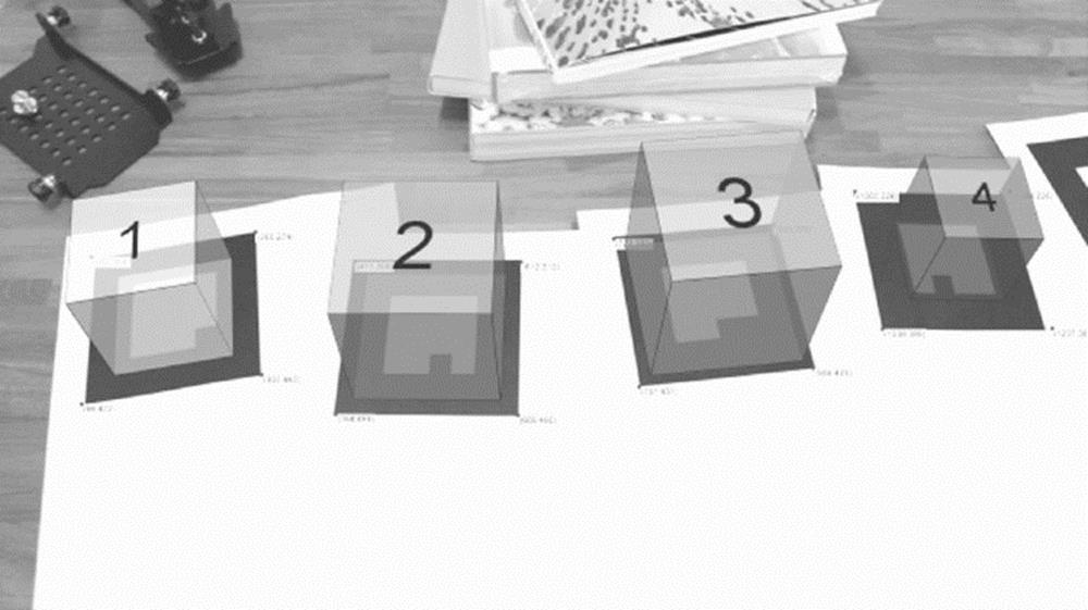
FIGURE 11.1 Augmented reality application (image courtesy of Amnon Owed)
NOTE
Read the full tutorial on how to generate AR applications in Processing (which in essence is nothing but a Java IDE) at:
http://www.creativeapplications.net/processing/augmented-reality-with-processing-tutorial-processing/
If you want to know more about Amnon Owed’s work, visit http://amnonp5.wordpress.com.
Google Glass has a transparent LCD that generates an overlay of information on top of whatever the user sees. In that sense it is an AR device. The following section has more details.
Google Glass
Google Glass’s strength is that it provides the user with an overlay of information on top of whatever he or she perceives thanks to a transparent LCD. Google Glass has some technology on board: it has a camera, some sensors, and the capability to communicate with a handheld. Ever since it was launched at Google I/O in June 2012, it has been the toy everyone in the tech industry wants to play with.
Regardless of its appeal, Google Glass is not a very innovative product. As mentioned in Chapter 1, although researchers have been working on this concept since the 1980s, this is the first time a company has tried to push a concept like this to the mainstream. Its designers intended Google Glass to be a day-to-day device that can be used by anyone in a nonintrusive way.
Figure 11.2 shows Google Glass version 2, a device not yet available.
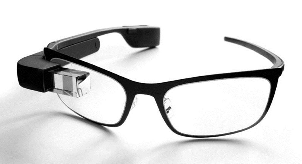
FIGURE 11.2 Google Glass (image by Mickepanhu, Creative Commons Attribution-ShareAlike 3.0 Unported)
Project Glass has generated some controversy. Its ubiquitous camera has heated up the discussion about the use of cameras in public spaces. Wearable-computing researcher Steve Mann encountered this issue when he traveled the world wearing his EyeTap device 24/7.
When designing wearable devices for everyday life, you must take into account the difference between what is socially acceptable today and what will be considered acceptable in the near future. Issues such as data ownership and privacy are relevant. Keep that in mind when you create your concepts for new apps.
Virtual Reality
VR is quite different from AR. The content in VR can be entirely synthetic. VR starts with the idea of having a head-mounted display that completely covers the user’s field of vision. It uses either a display or some sort of projective technology to show information to the user. One example of a VR device is Oculus Rift.
One of the main characteristics of VR is that the head-mounted display must be divided into two sections or one display for each eye. The latest implementations of this type of device use a single high-resolution display and a series of lenses to optically split the image in two. This is how the Oculus Rift operates.
Figure 11.3 shows the back view of the Oculus Rift development kit, dated 2012/2013. The device’s characteristic shape has to do with the display at the bottom.
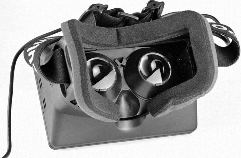
FIGURE 11.3 Oculus Rift (image courtesy of Sebastian Stabinger, CC BY 3.0)
The screen size of the original Oculus Rift display was barely 1280×800 pixels. This is not that much in comparison to the resolution of a high-end handheld. This fact is what inspired Google engineers David Coz and Damien Henry to make Cardboard—their own VR head-mounted display using just a mobile phone, some cardboard, a couple of lenses, and some other small parts.
VR on a Phone
It is a well-known fact that Google employees have the opportunity to devote 20 percent of their time to other endeavors. That is what Coz and Henry did when they came up with the idea of using a phone and a piece of software to create a VR device.
Contemporary phones have the computing power to run real-time OpenGL environments. Rendering stereoscopic images makes it possible to create a pair of images to stimulate each eye separately, creating the illusion of a real 3D image. You could use as input the images captured by two cameras or simply generate 3D shapes within a virtual world.
The creators of Google Cardboard had the simple but brilliant idea of creating a container for the glasses from inexpensive materials—cardboard in this case. Since the handheld is contained in a box, it is impossible or difficult to interact with the screen. Therefore, the creators considered two alternative input methods: near field communication (NFC) and magnetic fields.
The Cardboard prototype includes an NFC tag that triggers the event of launching a certain app in your phone. A strong neodymium magnet affects the magnetometer in the phone so that it can be used as a button by measuring abrupt changes in the magnetic field.
Figure 11.4 shows the original Google Cardboard, unfolded. The metallic disc is the magnet. The kit includes a pair of lenses and some Velcro as a fastener.
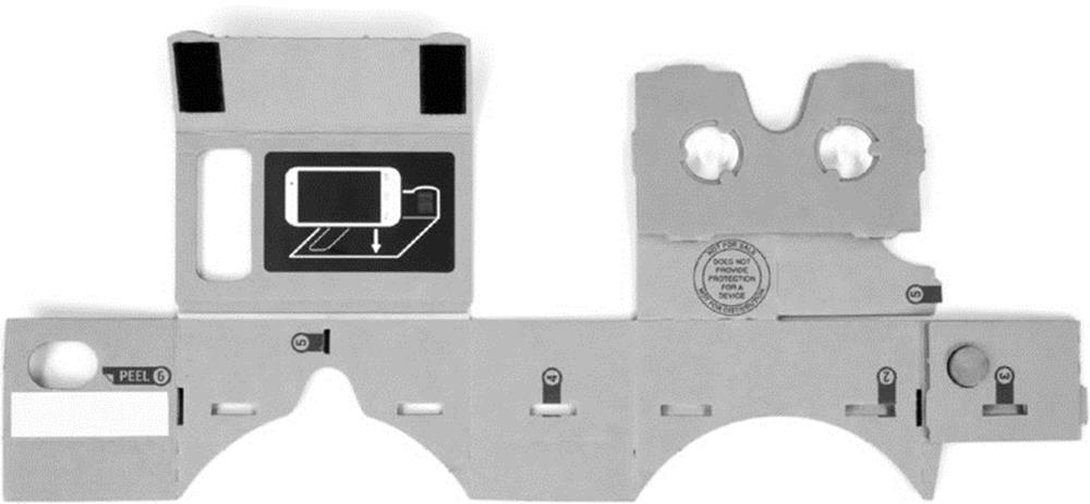
FIGURE 11.4 Unfolded Cardboard (image courtesy of Runner1928 Creative Commons Attribution-ShareAlike 4.0 International)
Currently you can purchase a DIY Google Cardboard kit at several places on the Internet. However, I will guide you through the process of making your own and controlling it from your Wear device instead of using the methods I mentioned: magnet plus NFC.
NOTE
Visit the official Google Cardboard project at https://cardboard.withgoogle.com/.
BUILDING YOUR OWN GLASSES
If you checked the link I just provided, you saw that part of the fun of the Cardboard project is to make it yourself. Since the arrival of this project in the summer of 2014, several vendors have begun selling their own version of the kit. Prices range between $5 and $30.
To build your own, you just need some cardboard, two small and identical magnifying lenses, some tape, and a rubber band or two. You also need your mobile phone. Don’t worry. It won’t be harmed during this experiment.
Figure 11.5 shows me wearing my personal Cardboard glasses. I didn’t really follow the original design from Google. It takes too many cuts, and I couldn’t find the specific type of lenses described on Google’s website.
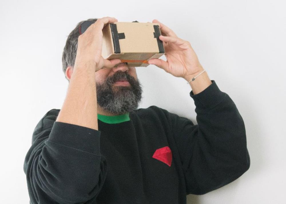
FIGURE 11.5 My personal Cardboard
Lenses
Cheap lenses are usually defined by their focal distance or zoom. The zoom is a multiplier that comes from making a division between the smallest and largest focal distance for a certain magnifying glass. The original Cardboard design recommends using a focal distance of 40mm (1.5 inches).
You can find lenses for as little as $1 up to as much as you want to pay. Cheap lenses are commonly defined by their zoom factor. I found a set of lenses with a 3X zoom for about $6 each at a local hardware store (see Figure 11.6). In my case they seem to be optimal at a distance of 100mm (4 inches) from the phone’s screen.
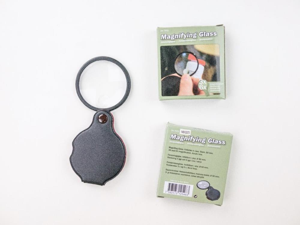
FIGURE 11.6 Lenses
To make your glasses work properly, you will have to fiddle a bit with the design I provide. If the focal distance is not set right, you will see a double image, a blurry one, or some other effect that will not make your experience the best one. Be ready to redo your box a couple of times; I did.
NOTE
You could visit Cardboard’s official website to get the original design files for the glasses—they are open source. Producing that design is far more complex as it is intended to be used with a lasercutter. The design suggested here is the Guerrilla version of Cardboard.
The Simplest Box Possible
This section is about making a box with tape, cardboard, and some love. I started with a cardboard box that was 140 × 200 × 280mm (5.5 × 8 × 11 inches). I broke it open and got a knife and some tape. You can see the design in Figure 11.7 . It should not take much effort to copy this design.
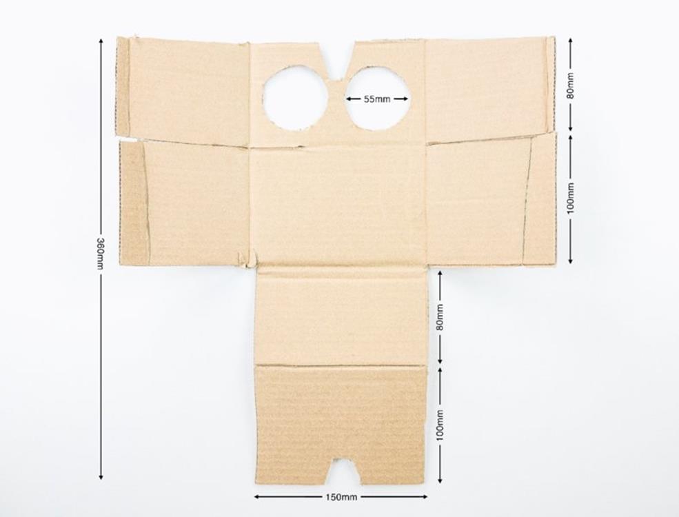
FIGURE 11.7 Box design
The trickiest part is attaching the lenses to the box. With the type of lenses I found, I had to add more tape to the design to make sure they wouldn’t move.
Figure 11.8 shows the final design. I kept the lens protectors because they made it easier to attach the lenses to the cardboard box.
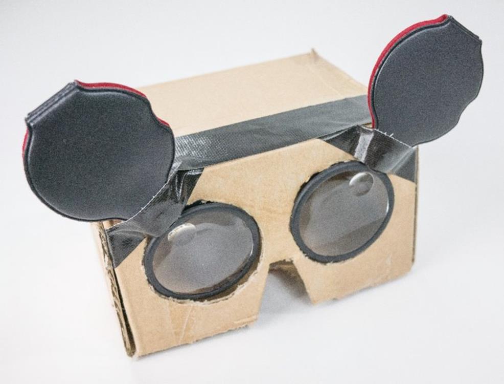
FIGURE 11.8 The final version of my Cardboard
THE SIMPLEST APP
The Cardboard documentation page offers a link to a github project that can be used to compile a simple application called “treasure hunt” that allows you to explore all the features of the VR library.
The sample code found today is ready for Android Studio. I have made sure the application compiles as an Android Studio workspace and made it available as a download. I created it starting from an empty Android Wear project for handheld and smartwatch, as explained in earlier chapters.
Figure 11.9 shows what you can expect to see on your screen after you have compiled the application and uploaded it to your handheld. This treasure hunt application was compiled using the Android Studio project provided as a download to this chapter. You can see a cube floating on top of a flat surface using stereoscopic projections. This is the “treasure.” You “hunt” for it by pressing the magnet on your Cardboard.
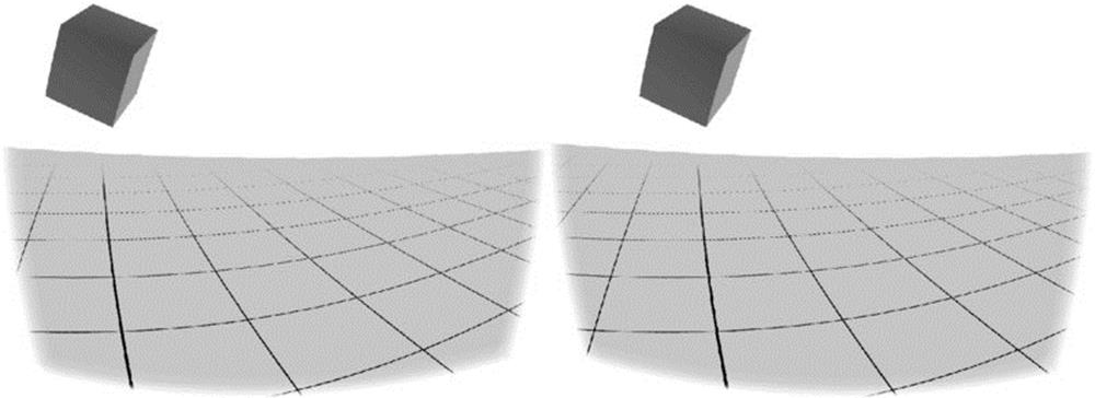
FIGURE 11.9 Treasure hunt app (the colors have been inverted for better visibility)
The goal is to add code to this app so that it uses the Wear API as an input.
NOTE
The simplest sample app for Cardboard can be found at the Cardboard development tutorials at https://developers.google.com/cardboard/overview.
If you want to see the github project where the original app for this project is located, visit https://github.com/googlesamples/cardboard/.
The cardboard.jar Library
The key to making the stereoscopic projection work is including in your project the VR Toolkit .jar file. This library is responsible for all the complex operations regarding the stereoscopic imaging and also adds access to the sensors.
You can find the binary version of the library at the github project mentioned in the preceding section. You should remember to add it to your compilation path. I recommend that you start working with the code example I created, which includes this binary already.
The following sections show you briefly how things work. It is not the goal of this chapter to teach you specifically about Google Cardboard, but about integrating an existing app with Android Wear.
Looking at the Code
We will start by looking at the main activity in the program. The idea is to understand how it works in order to find places to patch it. The example uses the magnetometer as a button. I will later substitute that functionality to use the smartwatch instead.
The Glasses’ MyActivityPhone.java
This class configures the use of the VR Toolkit library, as shown in Listing 11-1.
LISTING 11-1: Main Activity’s onCreate method (filename: MyActivityPhone.java)
package com.wiley.wrox.chapter11.cardboardglass;
import android.os.Bundle;
import android.content.Context;
import android.opengl.GLES20;
import android.opengl.Matrix;
import android.os.Vibrator;
import android.util.Log;
import com.google.vrtoolkit.cardboard.*;
import javax.microedition.khronos.egl.EGLConfig;
import java.io.BufferedReader;
import java.io.IOException;
import java.io.InputStream;
import java.io.InputStreamReader;
import java.nio.ByteBuffer;
import java.nio.ByteOrder;
import java.nio.FloatBuffer;
public class MyActivityPhone extends CardboardActivity
implements CardboardView.StereoRenderer {
[...]
/**
* Sets the view to our CardboardView and initializes the
* transformation matrices we will use to render our scene.
* @param savedInstanceState
*/
@Override
protected void onCreate(Bundle savedInstanceState) {
super.onCreate(savedInstanceState);
setContentView(R.layout.activity_my_phone);
CardboardView cardboardView =
(CardboardView) findViewById(R.id.cardboard_view);
cardboardView.setRenderer(this);
setCardboardView(cardboardView);
mModelCube = new float[16];
mCamera = new float[16];
mView = new float[16];
mModelViewProjection = new float[16];
mModelView = new float[16];
mModelFloor = new float[16];
mHeadView = new float[16];
mVibrator = (Vibrator) getSystemService(Context.VIBRATOR_SERVICE);
mOverlayView = (CardboardOverlayView) findViewById(R.id.overlay);
mOverlayView.show3DToast("Pull the magnet when you find an object.");
}
[...]
I have highlighted a few things in this code:
· ➤ Notice that the VR Toolkit from Google is needed for the code to compile.
· ➤ In the overridden version of onCreate(), after setting up the view and the renderer and initializing all the variables, the program initializes an instance of the vibrator. It gives the user physical feedback.
· ➤ When the program starts, it projects a sentence in the 3D space: “Pull the magnet when you find an object.” This gives a hint of what the user is expected to do when interacting with this application. This is one of the main aspects of our intervention in this code. We will get rid of the magnet and use the watch instead.
Listing 11-2 focuses on the onCardboardTrigger()method within the main class. This method is called when the magnet detects a sudden change in the magnetic field. With isLookingAtObject() it checks whether the handheld has rotated to an angle so that the user is facing a floating cube—the treasure in this game. If that is the case, a success message appears onscreen. If not, the user is encouraged to keep searching. Regardless of whether the user finds the object, the phone vibrates.
LISTING 11-2: onCardboardTrigger method (filename: MyActivityPhone.java)
/**
* Increment the score, hide the object, and give feedback if the
* user pulls the magnet while looking at the object. Otherwise,
* remind the user what to do.
*/
@Override
public void onCardboardTrigger() {
Log.i(TAG, "onCardboardTrigger");
if (isLookingAtObject()) {
mScore++;
mOverlayView.show3DToast("Found it! Look around for" +
"another one.\nScore = " + mScore);
hideObject();
} else {
mOverlayView.show3DToast("Look around to find the object!");
}
// Always give user feedback
mVibrator.vibrate(50);
}
Listing 11-3 shows the isLookingAtObject() method, which happens to be part of the code and not part of the library. It uses a series of methods belonging to the VR Toolkit library that aren’t within the scope of this experiment. I think it is worth taking a quick look at them just to see that they aren’t that scary.
LISTING 11-3: isLookingAtObject method (filename: MyActivityPhone.java)
/**
* Check if user is looking at object by calculating where
* the object is in eye-space.
* @return
*/
private boolean isLookingAtObject() {
float[] initVec = {0, 0, 0, 1.0f};
float[] objPositionVec = new float[4];
// Convert object space to camera space. Use the headView from onNewFrame.
Matrix.multiplyMM(mModelView, 0, mHeadView, 0, mModelCube, 0);
Matrix.multiplyMV(objPositionVec, 0, mModelView, 0, initVec, 0);
float pitch = (float)Math.atan2(objPositionVec[1], -objPositionVec[2]);
float yaw = (float)Math.atan2(objPositionVec[0], -objPositionVec[2]);
Log.i(TAG, "Object position: X: " + objPositionVec[0]
+ " Y: " + objPositionVec[1] + " Z: " + objPositionVec[2]);
Log.i(TAG, "Object Pitch: " + pitch +" Yaw: " + yaw);
return (Math.abs(pitch) < PITCH_LIMIT) && (Math.abs(yaw) < YAW_LIMIT);
}
In essence, the code checks whether the camera angle in the 3D environment the user is navigating is within the limits that should allow the user to see it floating over the ground. I highlighted the last line in the method, showing the logical statement that determines whether the conditions indicate that the user is looking at a cube.
The Glasses’ AndroidManifest.xml
Listing 11-4 shows the manifest file for the glasses. It highlights two different parts:
· ➤ A uses-permission tag to allow the app to use the NFC tag reader
· ➤ A uses-permission tag to allow the app to use the haptic feedback through the handheld’s vibrator
LISTING 11-4: Glasses’ manifest file (filename: AndroidManifest.xml)
<?xml version="1.0" encoding="utf-8"?>
<manifest xmlns:android="http://schemas.android.com/apk/res/android"
package="com.wiley.wrox.chapter11.cardboardglass" >
<uses-permission android:name="android.permission.NFC" />
<uses-permission android:name="android.permission.VIBRATE" />
<uses-feature android:glEsVersion="0x00020000" android:required="true" />
<application
android:allowBackup="true"
android:icon="@drawable/ic_launcher"
android:label="@string/app_name"
android:theme="@style/AppTheme" >
<activity
android:screenOrientation="landscape"
android:name=".MyActivityPhone"
android:label="@string/app_name" >
<intent-filter>
<action android:name="android.intent.action.MAIN" />
<category android:name="android.intent.category.LAUNCHER" />
</intent-filter>
</activity>
</application>
</manifest>
A Couple More Classes
Two more Java files are included in the phone’s part of the project. One handles the layout of the information on the 3D visualization, and the other contains simple information about the 3D objects. I will show you two code snippets to help you understand the content of those files. You could hack them easily to get them to do things differently.
Listing 11-5 shows an excerpt of CardboardOverlayView, a class that extends the linear layout to include two different visualizations: one for the left eye and one for the right.
LISTING 11-5: Excerpt of the CardboardOverlayView class (filename: CardboardOverlayView.java])
package com.wiley.wrox.chapter11.cardboardglass;
import [...]
/**
* Contains two subviews to provide a simple stereo HUD.
*/
public class CardboardOverlayView extends LinearLayout {
private static final String TAG = CardboardOverlayView.class.getSimpleName();
private final CardboardOverlayEyeView mLeftView;
private final CardboardOverlayEyeView mRightView;
private AlphaAnimation mTextFadeAnimation;
public CardboardOverlayView(Context context, AttributeSet attrs) {
super(context, attrs);
setOrientation(HORIZONTAL);
LayoutParams params = new LayoutParams(
LayoutParams.MATCH_PARENT, LayoutParams.MATCH_PARENT, 1.0f);
params.setMargins(0, 0, 0, 0);
mLeftView = new CardboardOverlayEyeView(context, attrs);
mLeftView.setLayoutParams(params);
addView(mLeftView);
mRightView = new CardboardOverlayEyeView(context, attrs);
mRightView.setLayoutParams(params);
addView(mRightView);
// Set some reasonable defaults.
setDepthOffset(0.016f);
setColor(Color.rgb(150, 255, 180));
setVisibility(View.VISIBLE);
mTextFadeAnimation = new AlphaAnimation(1.0f, 0.0f);
mTextFadeAnimation.setDuration(5000);
}
public void show3DToast(String message) {
setText(message);
setTextAlpha(1f);
mTextFadeAnimation.setAnimationListener(new EndAnimationListener() {
@Override
public void onAnimationEnd(Animation animation) {
setTextAlpha(0f);
}
});
startAnimation(mTextFadeAnimation);
}
[...]
I have chosen two methods in the class that I consider relevant to understanding how it works. First is the constructor, where you can see objects that display the data for each eye. Second is the show3DToast() method, which shows the text floating in front of your eyes while you navigate the 3D space. The rest of the class is basically a series of methods. They handle listeners as well as how to show text. More importantly, a helper class (not shown here) sets the layout of the canvas and text area for each eye.
Listing 11-6 shows an excerpt of WorldLayoutData, a class containing general information about the objects in the world. In this case, the array under the display contains information about the color of the cubes before the user finds them. “Finding” is the action of acknowledging having found the cube.
LISTING 11-6: Excerpt of the WorldLayoutData class (filename: WorldLayoutData.java)
public static final float[] CUBE_COLORS = new float[] {
// front, green
0f, 0.5273f, 0.2656f, 1.0f,
0f, 0.5273f, 0.2656f, 1.0f,
0f, 0.5273f, 0.2656f, 1.0f,
0f, 0.5273f, 0.2656f, 1.0f,
0f, 0.5273f, 0.2656f, 1.0f,
0f, 0.5273f, 0.2656f, 1.0f,
// right, blue
0.0f, 0.3398f, 0.9023f, 1.0f,
0.0f, 0.3398f, 0.9023f, 1.0f,
0.0f, 0.3398f, 0.9023f, 1.0f,
0.0f, 0.3398f, 0.9023f, 1.0f,
0.0f, 0.3398f, 0.9023f, 1.0f,
0.0f, 0.3398f, 0.9023f, 1.0f,
// back, also green
0f, 0.5273f, 0.2656f, 1.0f,
0f, 0.5273f, 0.2656f, 1.0f,
0f, 0.5273f, 0.2656f, 1.0f,
0f, 0.5273f, 0.2656f, 1.0f,
0f, 0.5273f, 0.2656f, 1.0f,
0f, 0.5273f, 0.2656f, 1.0f,
// left, also blue
0.0f, 0.3398f, 0.9023f, 1.0f,
0.0f, 0.3398f, 0.9023f, 1.0f,
0.0f, 0.3398f, 0.9023f, 1.0f,
0.0f, 0.3398f, 0.9023f, 1.0f,
0.0f, 0.3398f, 0.9023f, 1.0f,
0.0f, 0.3398f, 0.9023f, 1.0f,
// top, red
0.8359375f, 0.17578125f, 0.125f, 1.0f,
0.8359375f, 0.17578125f, 0.125f, 1.0f,
0.8359375f, 0.17578125f, 0.125f, 1.0f,
0.8359375f, 0.17578125f, 0.125f, 1.0f,
0.8359375f, 0.17578125f, 0.125f, 1.0f,
0.8359375f, 0.17578125f, 0.125f, 1.0f,
// bottom, also red
0.8359375f, 0.17578125f, 0.125f, 1.0f,
0.8359375f, 0.17578125f, 0.125f, 1.0f,
0.8359375f, 0.17578125f, 0.125f, 1.0f,
0.8359375f, 0.17578125f, 0.125f, 1.0f,
0.8359375f, 0.17578125f, 0.125f, 1.0f,
0.8359375f, 0.17578125f, 0.125f, 1.0f,
};
Once you execute this application on your Cardboard, the result you can expect will look like Figure 11.9.
Getting Your Cardboard to Talk to Your Smartwatch
Following the code examples from Chapter 7, it should be pretty straightforward to make your watch the input device to the app I just showed you. You import a couple of classes, modify the manifest file, include the Wearable API to send messages back and forth, make your own wearable app, and hack the onCardboardTrigger()method in your phone’s main activity. Piece of cake!
Let’s do this step by step. You will build two apps that will be connected through Google Play services. The watch displays the screen with a black background. When touched, it sends a message to the handheld indicating this. It also toggles the color. This example is unidirectional: We will send data from the wearable app to the phone app, but not the other way around. Implementing the communication in the other direction is not difficult using the code examples from previous chapters.
As in Chapter 7, you must take into account two things when dealing with such a scenario:
· ➤ How will you handle communication between devices? I will try using the Data API.
· ➤ How will you update the information on the devices’ screens? Like the case explored in Chapter 7, I will follow an event-based approach with a thread that responds to the arrival of data by changing the UI.
Start from the Previous Project
Start from the example we just finished. It contains all the code needed for building the Cardboard. You just need to patch the MyActivityPhone class in a couple of places. The project I prepared for you in the download area for this chapter includes a clean class for the Android Wear device.
The first step is to create the API client. You need only one object of the class DataItem shared between both devices, where one field represents the event of having touched the watch’s screen.
As usual, I will provide code snippets to give you an understanding of the code. For full code listings, check this chapter’s downloads.
The Phone’s MyActivityPhone.java
In MyActivityPhone.java, shown in Listing 11-7, you have to add a couple of things:
· ➤ The declaration of a Google API client to start sharing data between devices, with overrides to control the possibility of the connectivity’s being lost or not even started
· ➤ A local broadcast manager to capture the intents sent by the class listening to the data arriving from the smartwatch
LISTING 11-7: Modifications to the main activity on the phone app (filename: MyActivityPhone.java)
[...]
private GoogleApiClient mGoogleApiClient;
private BroadcastReceiver mResultReceiver;
[...]
@Override
protected void onCreate(Bundle savedInstanceState) {
super.onCreate(savedInstanceState);
setContentView(R.layout.activity_my_phone);
// declaration of the Google API client
mGoogleApiClient = new GoogleApiClient.Builder(this)
.addConnectionCallbacks(new GoogleApiClient.ConnectionCallbacks() {
@Override
public void onConnected(Bundle connectionHint) {
Log.v(TAG, "Connection established");
}
@Override
public void onConnectionSuspended(int cause) {
Log.v(TAG, "Connection suspended");
}
})
.addOnConnectionFailedListener(new
GoogleApiClient.OnConnectionFailedListener() {
@Override
public void onConnectionFailed(ConnectionResult result) {
Log.v(TAG, "Connection failed");
}
})
.addApi(Wearable.API)
.build();
mGoogleApiClient.connect();
mResultReceiver = createBroadcastReceiver();
LocalBroadcastManager.getInstance(this).registerReceiver(
mResultReceiver,
new IntentFilter("cardboard.localIntent"));
CardboardView cardboardView = (CardboardView)
findViewById(R.id.cardboard_view);
cardboardView.setRenderer(this);
setCardboardView(cardboardView);
mModelCube = new float[16];
mCamera = new float[16];
mView = new float[16];
mModelViewProjection = new float[16];
mModelView = new float[16];
mModelFloor = new float[16];
mHeadView = new float[16];
mVibrator = (Vibrator) getSystemService(Context.VIBRATOR_SERVICE);
mOverlayView = (CardboardOverlayView) findViewById(R.id.overlay);
mOverlayView.show3DToast("Pull the magnet when you find an object.");
}
[...]
private void onWearTouch() {
Log.v(TAG, "Arrived touch event");
if (isLookingAtObject()) {
mScore++;
mOverlayView.show3DToast("Found it! Look around "+
"for another one.\nScore = " + mScore);
hideObject();
} else {
mOverlayView.show3DToast("Look around to find the object!");
}
// Always give user feedback
mVibrator.vibrate(50);
}
@Override
protected void onDestroy() {
if (mResultReceiver != null) {
LocalBroadcastManager.getInstance(this)
.unregisterReceiver(mResultReceiver);
}
super.onDestroy();
}
private BroadcastReceiver createBroadcastReceiver() {
// we are just interested in the event, the rest doesn't matter
return new BroadcastReceiver() {
@Override
public void onReceive(Context context, Intent intent) {
onWearTouch();
}
};
}
As you can see, the basic idea is to call a method from the BroadcastReceiver and then perform a series of actions onscreen. In this case, it adds a point to the user’s record and vibrates. On top of that, you don’t need to sacrifice the possibility of using the magnet as an input. These new methods enhance your app without giving away anything (unless you want to do so).
The Phone’s AndroidManifest.xml
The service declaration is highlighted in Listing 11-8. This, together with the metadata tag declaring the use of the Google Play services API, are the two changes needed for the service to boot when the app launches and for the combo to use the Google Play Services API to talk to the other device.
LISTING 11-8: Full manifest file (filename: AndroidManifest.xml)
<?xml version="1.0" encoding="utf-8"?>
<manifest xmlns:android="http://schemas.android.com/apk/res/android"
package="com.wiley.wrox.chapter11.cardboardglass" >
<uses-permission android:name="android.permission.NFC" />
<uses-permission android:name="android.permission.VIBRATE" />
<uses-feature android:glEsVersion="0x00020000" android:required="true" />
<application
android:allowBackup="true"
android:icon="@drawable/ic_launcher"
android:label="@string/app_name"
android:theme="@style/AppTheme" >
<activity
android:screenOrientation="landscape"
android:name="MyActivityPhone"
android:label="@string/app_name" >
<intent-filter>
<action android:name="android.intent.action.MAIN" />
<category android:name="android.intent.category.LAUNCHER" />
</intent-filter>
</activity>
<service android:name=
"DataLayerListenerServicePhone" >
<intent-filter>
<action
android:name="com.google.android.gms.wearable.BIND_LISTENER" />
</intent-filter>
</service>
<meta-data android:name="com.google.android.gms.version"
android:value="@integer/google_play_services_version" />
</application>
</manifest>
The Phone’s DataLayerListenerService
DataLayerListenerService is launched on the phone after the app launches. When the phone registers an event of any of the shared data objects changing, the listener is triggered. In this case it filters by WEAR2PHONE. This object, as defined in MyActivityWear.java (see the source code in the next section), sends a boolean variable each time the screen is touched. The variable arriving from the Wear device toggles between true and false upon data arrival as a way to show progress.
Listing 11-9 shows the listener waiting for data to arrive from the watch. It is very similar to the one used in the last example of Chapter 7, only that this time there is no data going back from the phone to the watch.
LISTING 11-9: Full listener on the phone (filename: DataLayerListenerService.java)
package com.wiley.wrox.chapter11.cardboardglass;
import android.net.Uri;
import android.util.Log;
import com.google.android.gms.common.data.FreezableUtils;
import com.google.android.gms.wearable.DataEvent;
import com.google.android.gms.wearable.DataEventBuffer;
import com.google.android.gms.wearable.DataMap;
import com.google.android.gms.wearable.DataMapItem;
import com.google.android.gms.wearable.WearableListenerService;
import java.util.List;
public class DataLayerListenerServicePhone extends WearableListenerService {
private static String TAG = "wrox-mobile";
@Override
public void onDataChanged(DataEventBuffer dataEvents) {
super.onDataChanged(dataEvents);
Log.v(TAG, "Data arrived");
final List<DataEvent> events =
FreezableUtils.freezeIterable(dataEvents);
for(DataEvent event : events) {
final Uri uri = event.getDataItem().getUri();
final String path = uri!=null ? uri.getPath() : null;
if("/WEAR2PHONE".equals(path)) {
final DataMap map =
DataMapItem.fromDataItem(event.getDataItem()).getDataMap();
// read your values from map:
boolean touch = map.getBoolean("touch");
String reply = "Touched:" + touch;
Log.v(TAG, reply);
// if there was a touch, trigger the event detection
Intent localIntent = new Intent("cardboard.localIntent");
localIntent.putExtra("result", touch);
LocalBroadcastManager.getInstance(this)
.sendBroadcast(localIntent);
}
}
}
}
MyActivityWear.java
The activity on the watch (as shown on Listing 11-10) is simple. It needs to initialize the use of the data API and send data whenever the screen is touched. To make this easier to understand and to give the user visual feedback, the following things happen:
· ➤ The data is sent as WEAR2PHONE.
· ➤ The background color changes at each press. If the screen was white, it turns black, and vice versa.
· ➤ touchListener is implemented within the method dedicated to the layout. That’s where the action happens.
LISTING 11-10: Main activity class on the wearable (filename: MyActivityWear.java)
package com.wiley.wrox.chapter11.cardboardglass;
import android.app.Activity;
import android.graphics.Color;
import android.os.Bundle;
import android.support.wearable.view.WatchViewStub;
import android.util.Log;
import android.view.MotionEvent;
import android.view.View;
import android.widget.TextView;
import com.google.android.gms.common.ConnectionResult;
import com.google.android.gms.common.api.GoogleApiClient;
import com.google.android.gms.wearable.DataMap;
import com.google.android.gms.wearable.PutDataMapRequest;
import com.google.android.gms.wearable.Wearable;
public class MyActivityWear extends Activity {
private GoogleApiClient mGoogleApiClient;
private TextView mTextView;
private int mColor = Color.rgb(255,255,255);
private boolean mTouch = false;
private static final String TAG = "wrox-wear";
@Override
protected void onCreate(Bundle savedInstanceState) {
super.onCreate(savedInstanceState);
setContentView(R.layout.activity_my_wear);
mGoogleApiClient = new GoogleApiClient.Builder(this)
.addConnectionCallbacks(new
GoogleApiClient.ConnectionCallbacks() {
@Override
public void onConnected(Bundle connectionHint) {
Log.v(TAG, "Connection established");
}
@Override
public void onConnectionSuspended(int cause) {
Log.v(TAG, "Connection suspended");
}
})
.addOnConnectionFailedListener(new
GoogleApiClient.OnConnectionFailedListener() {
@Override
public void onConnectionFailed(ConnectionResult result) {
Log.v(TAG, "Connection failed");
}
})
.addApi(Wearable.API)
.build();
mGoogleApiClient.connect();
final WatchViewStub stub = (WatchViewStub)
findViewById(R.id.watch_view_stub);
stub.setOnLayoutInflatedListener(new
WatchViewStub.OnLayoutInflatedListener() {
@Override
public void onLayoutInflated(WatchViewStub stub) {
mTextView = (TextView) stub.findViewById(R.id.text);
stub.setOnTouchListener(new View.OnTouchListener() {
@Override
public boolean onTouch(View view, MotionEvent event) {
Log.v(TAG, "UI touched");
toggleBackgroundColor();
if(mGoogleApiClient==null)
return false;
final PutDataMapRequest putRequest =
PutDataMapRequest.create("/WEAR2PHONE");
final DataMap map = putRequest.getDataMap();
mTouch = !mTouch;
map.putBoolean("touch", mTouch);
Wearable.DataApi.putDataItem(mGoogleApiClient,
putRequest.asPutDataRequest());
return false;
}
});
}
});
}
private void toggleBackgroundColor(){
if (mColor == Color.rgb(0, 0, 0))
mColor = Color.rgb(255, 255, 255);
else
mColor = Color.rgb(0, 0, 0);
setBackgroundColor(mColor);
}
private void setBackgroundColor(int color) {
final WatchViewStub stub = (WatchViewStub)
findViewById(R.id.watch_view_stub);
stub.setBackgroundColor(color);
}
}
The Wear Android Manifest File
The only difference between the manifest file shown in Listing 11-11 and the default one when you create a new project is the call to Google Play that lets the wearable talk to the handheld inside your Cardboard glasses.
LISTING 11-11: Manifest file on the wearable (filename: AndroidManifest.xml)
<?xml version="1.0" encoding="utf-8"?>
<manifest xmlns:android="http://schemas.android.com/apk/res/android"
package="com.wiley.wrox.chapter11.cardboardglass" >
<uses-feature android:name="android.hardware.type.watch" />
<application
android:allowBackup="true"
android:icon="@drawable/ic_launcher"
android:label="@string/app_name"
android:theme="@android:style/Theme.DeviceDefault" >
<activity
android:name=
"MyActivityWear"
android:label="@string/app_name" >
<intent-filter>
<action android:name="android.intent.action.MAIN" />
<category android:name="android.intent.category.LAUNCHER" />
</intent-filter>
</activity>
<meta-data android:name="com.google.android.gms.version"
android:value="@integer/google_play_services_version" />
</application>
</manifest>
The Final Result
As usual, I recommend that you check the full example in the file chapter11_CardboardGlass_touch.zip. There you will find all the code used for this example, ready for you to copy and start experimenting with in your own applications.
The expected result on your side should look like Figure 11.9, which shows the activity on my phone. When touching the screen of your wearable and being in front of a cube (it will be highlighted in yellow), you earn a point.
SUMMARY
You have learned how to integrate Wear into an existing block of code. In this chapter we enhanced the functionality of an existing app by adding touch interaction through the wearable.
You also had a chance to experiment with one of the most promising libraries of code in the world of DIY head-mounted displays—the VR Toolkit used to power Google Cardboard.
From a more theoretical standpoint, you were introduced to augmented reality and virtual reality. You read about the different products you can use to build experiences for both.
All materials on the site are licensed Creative Commons Attribution-Sharealike 3.0 Unported CC BY-SA 3.0 & GNU Free Documentation License (GFDL)
If you are the copyright holder of any material contained on our site and intend to remove it, please contact our site administrator for approval.
© 2016-2026 All site design rights belong to S.Y.A.