Make: Basic Arduino Projects - 26 Experiments with Microcontrollers and Electronics (2014)
Chapter 1. The Trick Switch
Resistor-Capacitor Timing Basics
In electronics, sometimes we want to keep a device on for a certain amount of time even when an electrical switch is turned off. Ordinary pushbuttons used to turn electronic devices on and off can easily be operated by a timed delay switch. How awesome would it be to create such a device to delay turning off a simple LED? Such a gadget could be used to trick your friends, family, or even the local Makerspace when they see the LED staying on after the pushbutton has been released. With a few electronic components from the Ultimate Microcontroller Pack, you can make an LED (light-emitting diode) stay on for a few extra seconds when a pushbutton switch is turned off. Figure 1-1 shows an assembled Trick Switch. The electronic components required to build the Trick Switch are shown in the Parts List.
Parts List
§ Arduino microcontroller
§ SW1: mini pushbutton
§ LED1: red LED
§ C1: 100 uF electrolytic capacitor
§ R1: 10K ohm resistor (brown, black, orange stripes)
§ R2: 330 ohm resistor (orange, orange, brown stripes)
§ Full-size clear breadboard
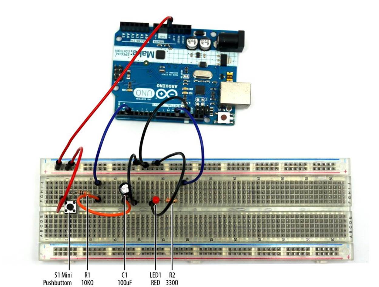
Figure 1-1. Trick Switch circuit built on a full-size clear breadboard (both the 100 uF electrolytic capacitor and red LED negative pins are wired to ground)
TECH NOTE
You can create your own electrical circuits and test them using diagrams with an online simulator called Circuit Lab.
Let’s Build a Trick Switch
When you press the pushbutton switch on this device, the LED turns on. The capacitor will begin storing electrical energy from the +5VDC power supply circuit of the Arduino. Releasing the pushbutton switch cuts off the flow of electricity from the source, but the energy stored in the capacitor keeps the Arduino running for a few extra seconds. The Arduino keeps the LED lit until the capacitor’s stored energy is empty. You can build the Trick Switch using the electronic components from the Parts List and the Fritzing wiring diagram shown in Figure 1-2. Here are the steps required to build the electronic device:
1. From the Ultimate Microcontroller Pack, place the required parts on your workbench or lab tabletop.
2. Wire the electronic parts using the Fritzing wiring diagram of Figure 1-2 or the actual Trick Switch device shown in Figure 1-1.
3. Type the Pushbutton sketch shown in Example 1-1 into the Arduino text editor.
4. Upload the Pushbutton sketch to the Arduino.
5. Press the mini pushbutton for a moment. The red LED turns on. After one to two minutes, the red LED will turn off.
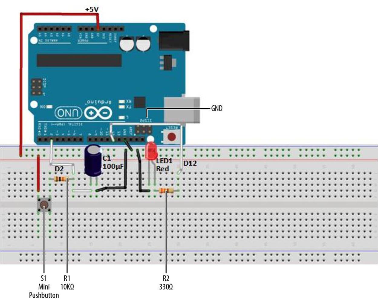
Figure 1-2. Trick Switch Fritzing diagram
TROUBLESHOOTING TIP
If the Trick Switch device doesn’t work, check for incorrect resistor values, incorrect wiring, sketch typos, and improper orientation of polarized electronic components (the LED and capacitor).
Example 1-1. Pushbutton sketch
/*
Pushbutton Sketch
Reads the capacitor voltage at digital pin 2 and turns on and off a light-
emitting diode (LED) connected to digital pin 12.
17 Nov 2012
by Don Wilcher
*/
// constants won't change; they're used here to
// set pin numbers:
const int buttonPin = 2; // the number of the pushbutton pin
const int ledPin = 12; // the number of the LED pin
// variables will change:
int buttonStatus = 0; // variable for reading the pushbutton status
void setup() {
// initialize the LED pin as an output:
pinMode(ledPin, OUTPUT);
// initialize the pushbutton pin as an input:
pinMode(buttonPin, INPUT);
}
void loop(){
// read the status of the pushbutton value:
buttonStatus = digitalRead(buttonPin);
// check if the pushbutton is pressed
// if it is, the buttonEvent is HIGH:
if (buttonStatus == HIGH) {
// turn LED on:
digitalWrite(ledPin, HIGH);
}
else {
// turn LED off:
digitalWrite(ledPin, LOW);
}
}
TECH NOTE
The ledPin value can be changed to 13 to operate the onboard LED.
Trick Switch with On/Off Indicators
In developing new products, electronics designers are always improving designs by adding features and functions that excite the customer. The Trick Switch device you built can be improved by adding an LED indicator. This LED indicates when the Trick Switch timing cycle is done.Figure 1-3 shows you where to add a green LED to the Trick Switch on the full-size clear breadboard.
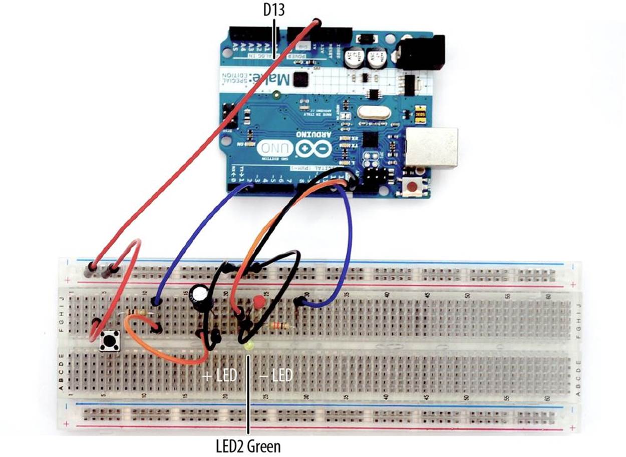
Figure 1-3. Adding a green LED indicator to the Trick Switch circuit built on a full-size clear breadboard
To complete the new product design, you need to make a few changes to the Pushbutton sketch. Modify the sketch using the code changes shown in Example 1-2.
Example 1-2. Pushbutton sketch modified to include LED indicators
// constants won't change; they're used here to
// set pin numbers:
const int buttonPin = 2; // the number of the pushbutton pin
const int ledPin = 12; // the number of the LED pin
const int ledPin13 = 13; // onboard LED
void setup() {
// initialize the LED pins as outputs:
pinMode(ledPin, OUTPUT);
pinMode(ledPin13, OUTPUT);
// initialize the pushbutton pin as an input:
pinMode(buttonPin, INPUT);
}
void loop(){
// read the state of the pushbutton value:
int buttonStatus;
buttonStatus = digitalRead(buttonPin);
// check if the pushbutton is pressed
// if it is, the buttonStatus is HIGH:
if (buttonStatus == HIGH) {
// turn LED on:
digitalWrite(ledPin, HIGH);
// turn off onboard LED:
digitalWrite(ledPin13,LOW);
}
else {
// turn LED off:
digitalWrite(ledPin, LOW);
// turn on onboard LED:
digitalWrite(ledPin13, HIGH);
}
}
After you’ve saved the sketch changes and uploaded them to the Arduino, the green LED will turn on. When you press the mini pushbutton, the green LED will turn off, and the red LED will turn on. Pretty awesome stuff. Enjoy!
The block diagram in Figure 1-4 shows the electronic component blocks and the electrical signal flow for the Trick Switch. A Fritzing electronic circuit schematic diagram of the switch is shown in Figure 1-5. Electronic circuit schematic diagrams are used by electrical/electronic engineers to design and build cool electronic products for society.
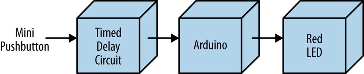
Figure 1-4. Trick Switch block diagram
Something to Think About
Try different resistor and capacitor values and see what happens. Can you detect any patterns? How can a small piezo buzzer be used with the Trick Switch?
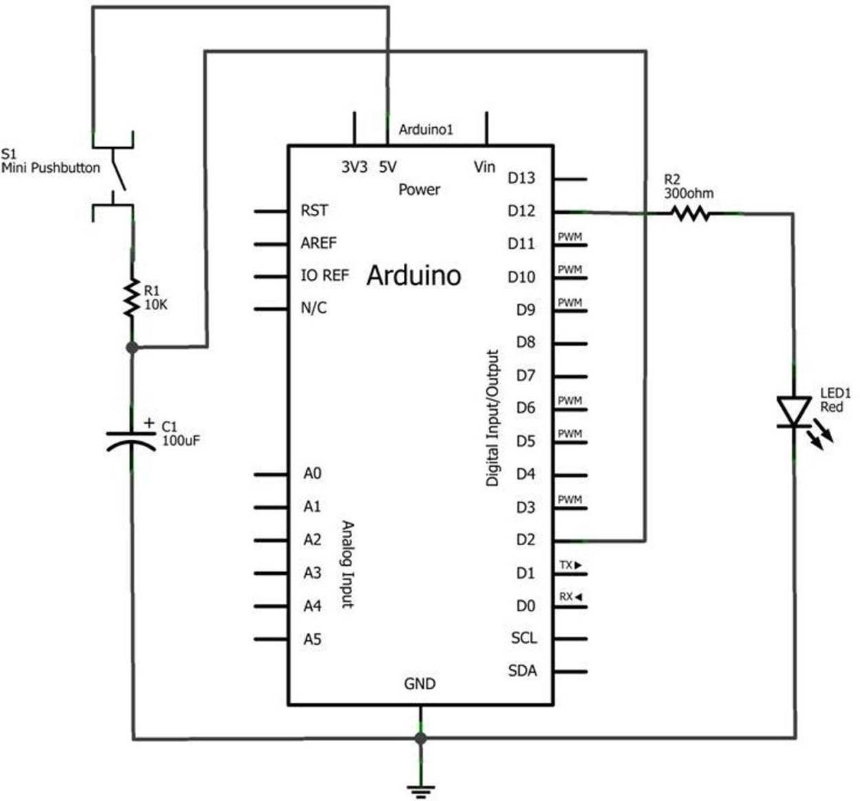
Figure 1-5. Trick Switch circuit schematic diagram