Arduino: A Quick-Start Guide, Second Edition (2015)
Part I. Getting Started with Arduino
Chapter 2. Creating Bigger Projects with the Arduino
For simple applications, what you learned about the Arduino IDE in the preceding chapter is sufficient. But soon your projects will get more ambitious, and then it will be handy to split them into separate files that you can manage as a whole. So in this chapter, you’ll learn how to stay in control of bigger projects with the Arduino IDE.
Usually, bigger projects need not only more software, but also more hardware—you will rarely use the Arduino board in isolation. You will use many more sensors than you might imagine, and you’ll have to transmit the data they measure back to your computer. To exchange data with the Arduino, you’ll use its serial port. This chapter explains everything you need to know about serial communication. To make things more tangible, you’ll learn how to turn your computer into a very expensive light switch that lets you control an LED using the keyboard.
What You Need
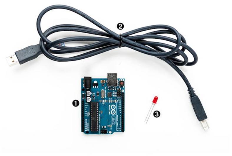
To try this chapter’s examples, you need only a few things:
1. An Arduino board, such as the Uno, Duemilanove, or Diecimila
2. A USB cable to connect the Arduino to your computer
3. An LED (optional)
4. A software serial terminal such as PuTTY (for Windows users) or screen for Linux and Mac OS X users (optional)
Managing Projects and Sketches
Modern software developers can choose from a variety of development tools that automate repetitive and boring tasks. That’s also true for embedded systems like the Arduino. You can use integrated development environments (IDEs) to manage your programs, too. The most popular one has been created by the Arduino team.
The Arduino IDE manages all files belonging to your project. It also provides convenient access to all the tools you need to create the binaries that will run on your Arduino board. Conveniently, it does so unobtrusively.
Organizing all the files belonging to a project automatically is one of the most important features of an IDE. Under the hood, the Arduino IDE creates a directory for every new project, storing all the project’s files in it. To add new files to a project, click the Tabs button on the right to open the Tabs pop-up menu, and then choose New Tab (Figure 7, The Tabs menu in action). To add an existing file, use the Sketch > Add File menu item.
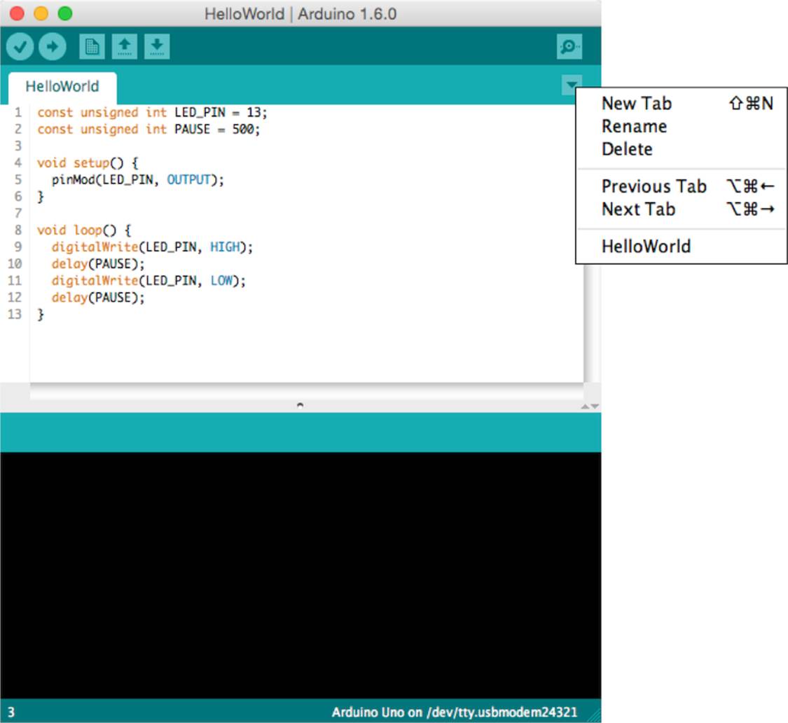
Figure 7. The Tabs menu in action
As you might have guessed from the names of the menu items, the Arduino IDE calls projects sketches. If you create a new sketch, the IDE gives it a name starting with sketch_. You can change the name whenever you like using the Save As command. If you do not save a sketch explicitly, the IDE stores it in a predefined folder you can look up in the Preferences menu. Whenever you get lost, you can check what folder the current sketch is in using the Sketch > Show Sketch Folder menu item.
Since Arduino 1.0, sketches have the extension ino. Older IDE versions used pde. Arduino 1.0 still supports pde files, but it will update them to ino when you save the sketch. (You can disable this behavior in the Preferences menu.)
Not only can you create your own sketches using the IDE, but it also comes with many example sketches that you can use as a basis for your own experiments. Get to them via the File > Examples menu. Take some time to browse through them, even if you don’t understand anything you see right now.
Note that many libraries come with examples, too. Whenever you install a new library (you’ll learn how to do this later), you should have a look at the File > Examples menu again. It will probably contain new entries.
The Arduino IDE makes your life easier by choosing reasonable defaults for many settings. But it also allows you to change most of these settings, and you’ll see how in the next section.
Changing Preferences
For your early projects, the IDE’s defaults might be appropriate, but sooner or later you’ll want to change some things. As you can see in the following figure, the IDE lets you change only a few preferences directly.
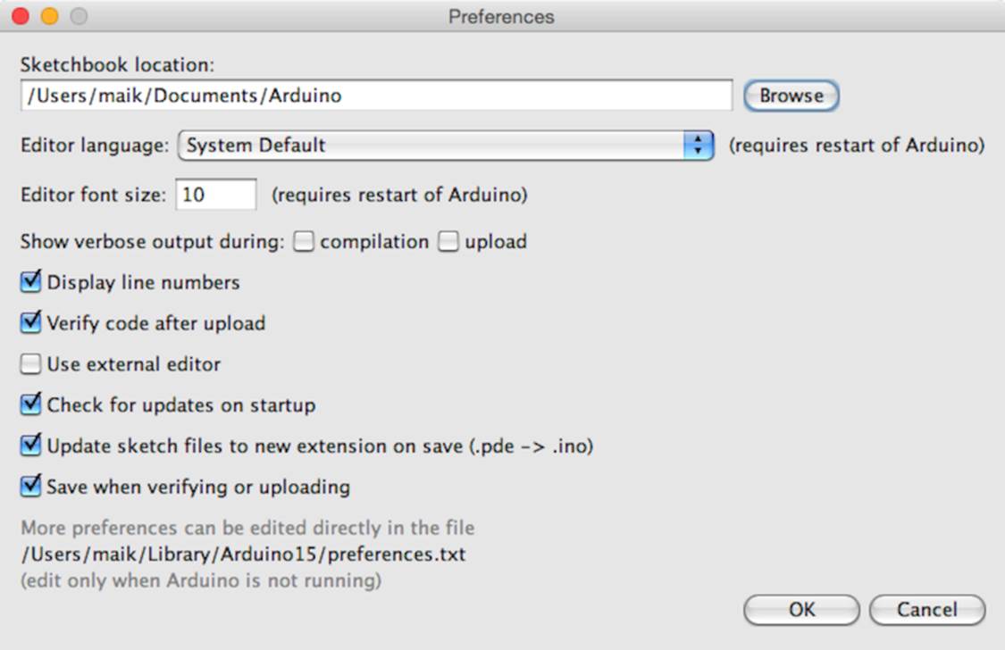
The dialog box refers to a file named preferences.txt containing more preferences. This file is a Java properties file consisting of key/value pairs. Here you see a few of them:
|
|
... |
|
|
preproc.web_colors=true |
|
|
editor.font=Monaco,plain,10 |
|
|
update.check=true |
|
|
build.verbose=true |
|
|
upload.verbose=true |
|
|
... |
Most of these properties control the user interface; that is, they change fonts, colors, and so on. But they can also change the application’s behavior. You can enable more verbose output for operations such as compiling or uploading a sketch. Before Arduino 1.0, you had to editpreferences.txt and set both build.verbose and upload.verbose to true to achieve this. Today, you can change the verbose settings from the Preferences dialog box. Make sure that verbose output is enabled for compilation and upload. Also, it’s helpful to enable the “Display line numbers” option.
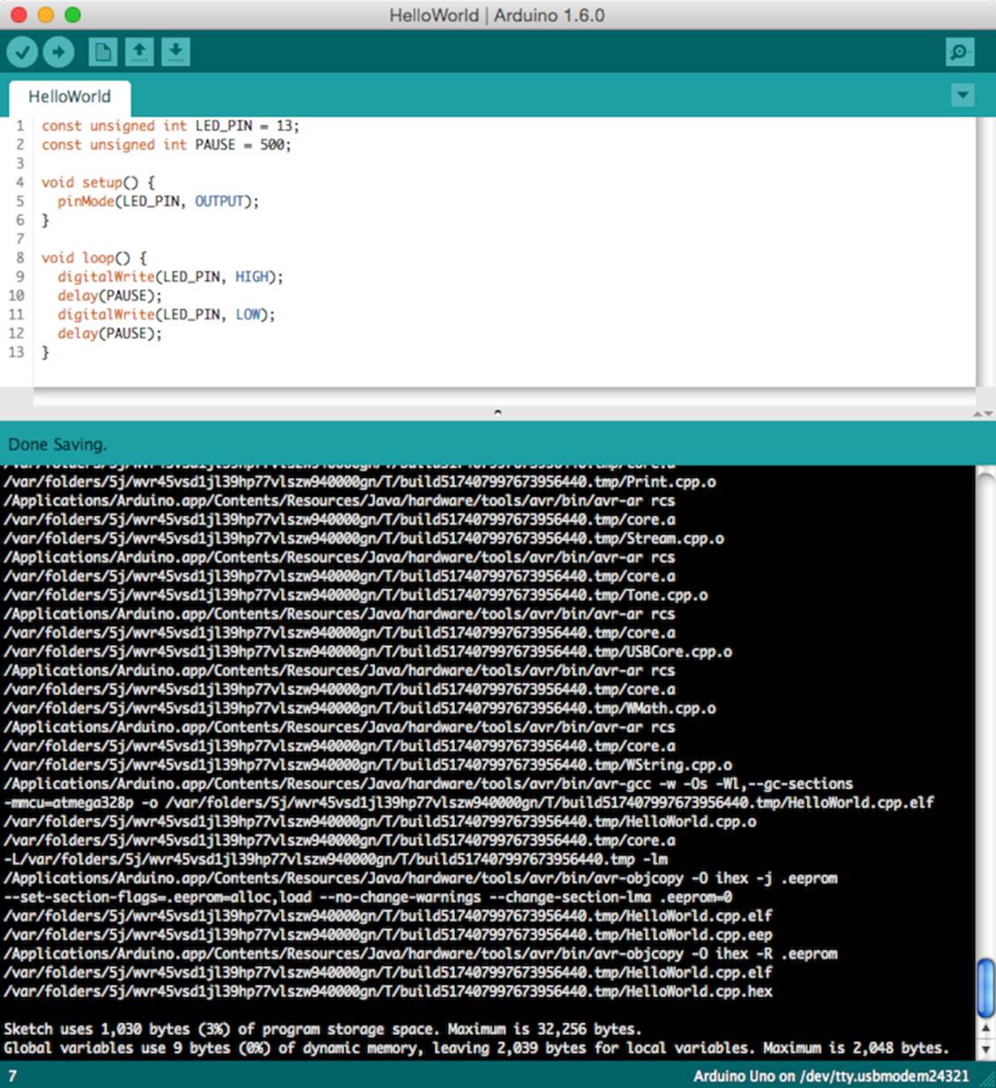
Load the blinking LED sketch from Chapter 1, Welcome to the Arduino, and compile it again. The output in the message panel should look like this:
Note that the IDE updates some of the Preferences values when it shuts down. So before you change any preferences directly in the preferences.txt file, you have to stop the Arduino IDE.
Now that you’re familiar with the Arduino IDE, let’s do some programming. We’ll make the Arduino talk to the outside world.
The Arduino Programming Language
People sometimes get irritated when it comes to the language the Arduino gets programmed in. That’s mainly because the typical sample sketches look as if they were written in a language that was exclusively designed for programming the Arduino. But that’s not the case—it is plain old C++ (which implies that it supports C, too).
Most Arduino boards use an AVR microcontroller designed by a company named Atmel. (Atmel says that the name AVR doesn’t stand for anything.) These microcontrollers are very popular, and many hardware projects use them. One reason for their popularity is the excellent tool chain that comes with them. Based on the GNU C++ compiler tools, it is optimized for generating code for AVR microcontrollers.
That means you feed C++ code to the compiler that is not translated into machine code for your computer, but for an AVR microcontroller. This technique is called cross-compiling and is the usual way to program embedded devices.
Using Serial Ports
Arduino makes many stand-alone applications—projects that do not involve any additional computers—possible. In such cases you need to connect the Arduino to a computer once to upload the software, and after that, it needs only a power supply. More often, people use the Arduino to enhance the capabilities of a computer using sensors or by giving access to additional hardware. Usually, you control external hardware via a serial port, so it is a good idea to learn how to communicate serially with the Arduino.
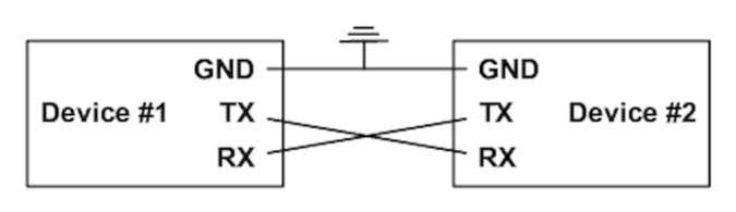
Although the standards for serial communication have changed over the past years (for example, we use USB today, and our computers no longer have RS232 connectors), the basic working principles remain the same. In the simplest case, we can connect two devices using only three wires: a common ground, a line for transmitting data (TX), and one for receiving data (RX).
Serial communication might sound old-school, but it’s still the preferred way for hardware devices to communicate. The S in USB stands for “serial”—and when was the last time you saw a parallel port? (Perhaps this is a good time to clean up the garage and throw out that old PC you wanted to turn into a media center someday….)
For uploading software, the Arduino has a serial port, and you can use it to connect the Arduino to other devices, too. (In Compiling and Uploading Programs, you learned how to look up the serial port your Arduino is connected to.) In this section, you’ll use the serial port to control Arduino’s status LED using your computer’s keyboard. The LED should be turned on when you press 1, and it should be turned off when you press 2. Here’s all the code you need:
|
Welcome/LedSwitch/LedSwitch.ino |
|
|
Line 1 |
const unsigned int LED_PIN = 13; |
|
- |
const unsigned int BAUD_RATE = 9600; |
|
- |
|
|
- |
void setup() { |
|
5 |
pinMode(LED_PIN, OUTPUT); |
|
- |
Serial.begin(BAUD_RATE); |
|
- |
} |
|
- |
|
|
- |
void loop() { |
|
10 |
if (Serial.available() > 0) { |
|
- |
int command = Serial.read(); |
|
- |
if (command == '1') { |
|
- |
digitalWrite(LED_PIN, HIGH); |
|
- |
Serial.println("LED on"); |
|
15 |
} else if (command == '2') { |
|
- |
digitalWrite(LED_PIN, LOW); |
|
- |
Serial.println("LED off"); |
|
- |
} else { |
|
- |
Serial.print("Unknown command: "); |
|
20 |
Serial.println(command); |
|
- |
} |
|
- |
} |
|
- |
} |
As in our previous examples, we define a constant for the pin the LED is connected to and set it to OUTPUT mode in the setup function. In line 6, we initialize the serial port using the begin function of the Serial class, passing a baud rate of 9600. (You can learn what a baud rate is inLearning More About Serial Communication.) That’s all we need to send and receive data via the serial port in our program.
So, let’s read and interpret the data. The loop function starts by calling Serial’s available method in line 10. available returns the number of bytes waiting on the serial port. If any data is available, we read it using Serial.read. read returns the first byte of incoming data if data is available and -1 otherwise.
If the byte we have read represents the character 1, we switch on the LED and send back the message “LED on” over the serial port. We use Serial.println, which adds a carriage return character (ASCII code 13) followed by a newline (ASCII code 10) to the text.
If we receive the character 2, we switch off the LED. If we receive an unsupported command, we send back a corresponding message and the command we didn’t understand. Serial.print works exactly like Serial.println, but it doesn’t add carriage return and newline characters to the message.
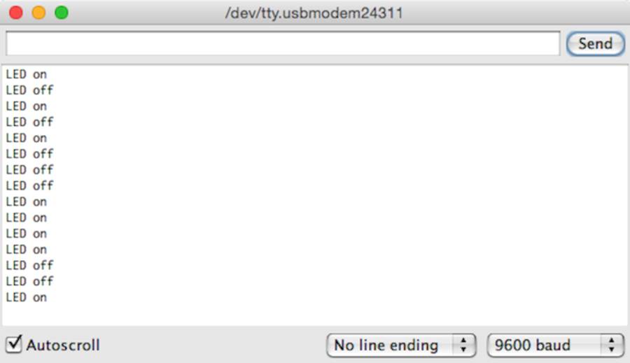
Let’s see how the program works in practice. Compile it, upload it to your Arduino, and then switch to the serial monitor. At first glance, nothing happens. That’s because we haven’t sent a command to the Arduino yet. Make sure the drop-down menu at the bottom of the serial monitor is set to No line ending. Enter a 1 in the text box, and then click the Send button. Two things should happen now: the LED is switched on, and the message “LED on” appears in the serial monitor window (as shown in the following image). We are controlling an LED using our computer’s keyboard!
Play around with the commands 1 and 2, and also observe what happens when you send an unknown command. If you type in an uppercase A, the Arduino will send back the message “Unknown command: 65.” The number 65 is the ASCII code of the letter A, and the Arduino outputs the data it got in its most basic form. That’s the default behavior of Serial’s print method, and you can change it by passing a format specifier to your function calls. To see the effect, replace line 20 with the following statements:
|
|
Serial.println(command, DEC); |
|
|
Serial.println(command, HEX); |
|
|
Serial.println(command, OCT); |
|
|
Serial.println(command, BIN); |
|
|
Serial.write(command); |
|
|
Serial.println(); |
The output looks as follows when you send the character A again:
|
|
Unknown command: 65 |
|
|
41 |
|
|
101 |
|
|
1000001 |
|
|
A |
Depending on the format specifier, Serial.println automatically converts a byte into another representation. DEC outputs a byte as a decimal number, HEX as a hexadecimal number, and so on. Note that such an operation usually changes the length of the data that get transmitted. The binary representation of the single byte 65 needs 7 bytes, because it contains seven characters. Also note that we have to use Serial.write instead of Serial.println to output a character representation of our command value. Former versions of the Arduino IDE had a BYTE modifier for this purpose, but it has been removed in Arduino 1.0.
Numbering Systems
It’s an evolutionary accident that 10 is the basis for our numbering system. If we had only four fingers on each hand, it’d be probably eight, and we’d probably have invented computers a few centuries earlier.
For thousands of years, people have used denominational number systems, and we represent a number like 4711 as follows:
4×10³ + 7×10² + 1×101 + 1×100
This makes arithmetic operations very convenient. But when working with computers that interpret only binary numbers, it’s often good to use numbering systems based on the numbers 2 (binary), 8 (octal), or 16 (hexadecimal).
The decimal number 147 can be represented in octal and hexadecimal as:
|
2×82 |
+ |
2×81 |
+ |
3×80 |
= |
0223 |
|
9×161 |
+ |
3×160 |
= |
0x93 |
In Arduino programs, you can define literals for all these numbering systems:
|
|
int decimal = 147; |
|
|
int binary = B10010011; |
|
|
int octal = 0223; |
|
|
int hexadecimal = 0x93; |
Binary numbers start with a B character, octal numbers with a 0, and hexadecimal numbers with 0x. Note that you can use binary literals only for numbers from 0 to 255.
Using Different Serial Terminals
For trivial applications, the IDE’s serial monitor is sufficient, but you cannot easily combine it with other applications, and it lacks some features. That means you should have an alternative serial terminal to send data, and you can find plenty of them for every operating system.
Serial Terminals for Windows
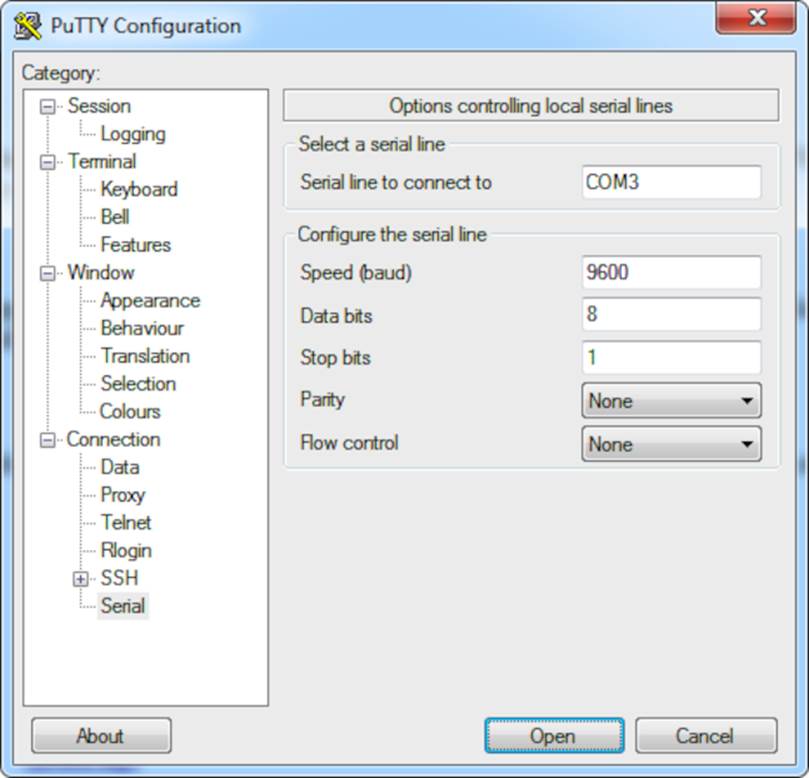
PuTTY[38] is an excellent choice for Windows users. It is free, and it comes as an executable that doesn’t even have to be installed. The following figure shows how to configure it for communication on a serial port.
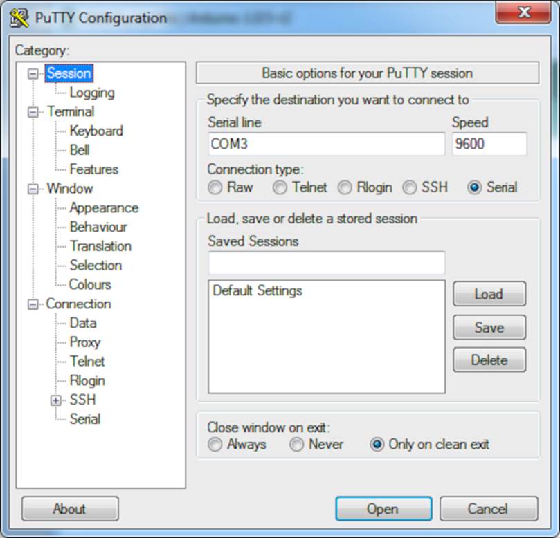
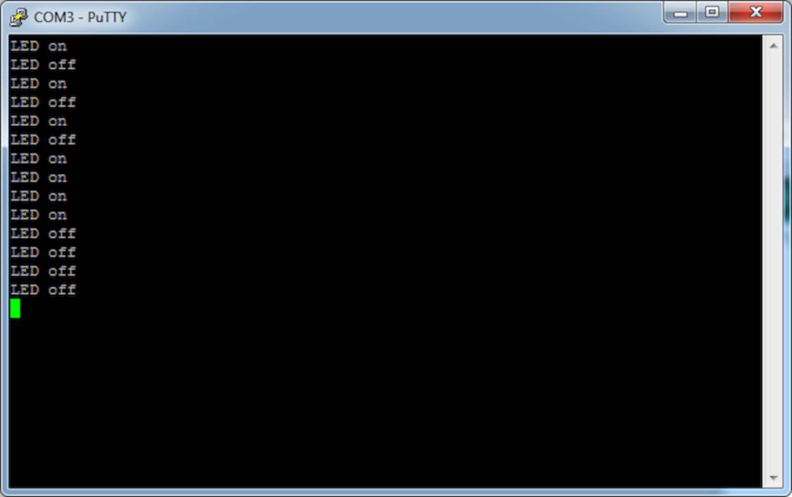
After you have configured PuTTY, you can open a serial connection to the Arduino. The following screenshot shows the corresponding dialog box. Click Open, and you’ll see an empty terminal window.
Now press 1 and 2 a few times to switch on and off the LED.
Serial Terminals for Linux and Mac OS X
Linux and Mac users can use the screen command to communicate with the Arduino on a serial port. Check which serial port the Arduino is connected to in the IDE’s Tools > Board menu. Then run a command like this (with an older board the name of the serial port might be something like/dev/tty.usbserial-A9007LUY, and on Linux systems it might be /dev/ttyUSB1 or something similar):
|
|
$ screen /dev/tty.usbmodem24321 9600 |
The screen command expects the name of the serial port and the baud rate to be used. To quit the screen command, press Ctrl-a followed by k. (On some systems it’s Ctrl-a followed by Ctrl-k.)
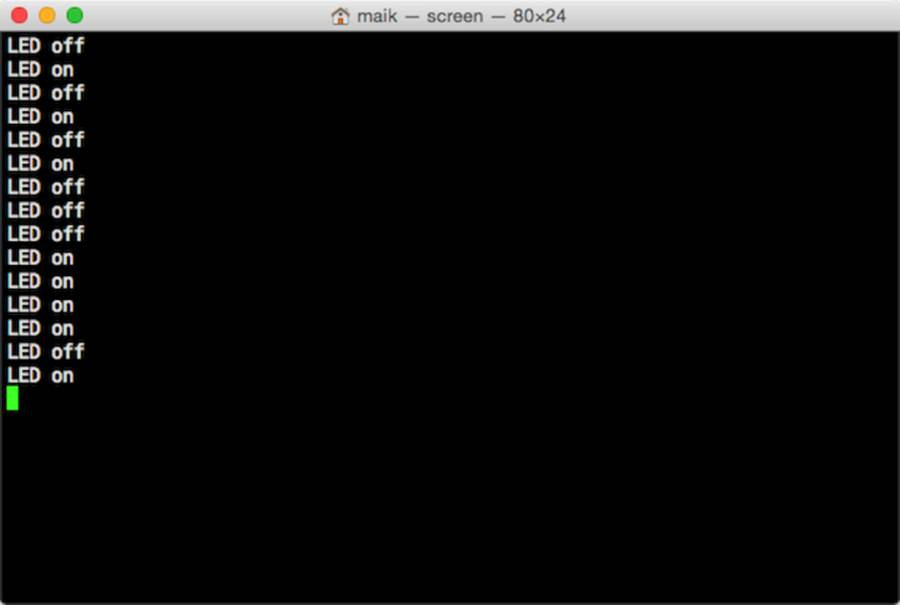
We can now communicate with the Arduino, and this has great implications: whatever is controlled by the Arduino can also be controlled by your computer, and vice versa. Switching LEDs on and off isn’t too spectacular, but try to imagine what’s possible now. You could move robots, automate your home, or create interactive games.
Here are some more important facts about serial communication:
· The Arduino Uno’s serial receive buffer can hold up to 64 bytes. When sending large amounts of data at high speed, you have to synchronize sender and receiver to prevent data loss. Usually, the receiver sends an acknowledgment to the sender whenever it is ready to consume a new chunk of data.
· You can control many devices using serial communication, but the regular Arduino has only one serial port. If you need more, take a look at the Arduino Due, which has four serial ports.[39]
· A Universal Asynchronous Receiver/Transmitter (UART)[40] device supports serial communication on the Arduino. This device handles serial communication while the CPU takes care of other tasks. This greatly improves the system’s overall performance. The UART uses digital pins 0 (RX) and 1 (TX), which means you cannot use them for other purposes when communicating on the serial port. If you need them, you can disable serial communication using Serial.end().
· With the SoftwareSerial[41] library, you can use any digital pin for serial communication. It has some limitations, but it is sufficient for most applications.
In this chapter, you saw how to communicate with the Arduino using the serial port, which opens the door to a whole new world of physical computing projects. (See Learning More About Serial Communication, for more details about serial communication.) In the next chapters, you’ll learn how to gather interesting facts about the real world using sensors, and you’ll learn how to change the real world by moving objects. Serial communication is the basis for letting you control all of these actions using the Arduino and your PC.
What If It Doesn’t Work?
If anything goes wrong with the examples in this chapter, you should take a look at What If It Doesn’t Work?, first. If you still run into problems, it may be because of some issues with serial communication. You might have set the wrong baud rate; in the following figure, you can see what happens in such a case.
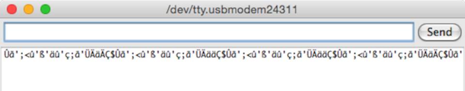
Make sure that the baud rate you’ve set in your call to Serial.begin matches the baud rate in the serial monitor.
Exercises
· Add new commands to the sample program. The command 3 could make the LED blink for a while.
· Try to make the commands more readable; that is, instead of 1, use the command “on”, and instead of 2, use “off”.
If you have problems solving these exercises, read Chapter 4, Building a Morse Code Generator Library.
Footnotes
|
[38] |
http://www.chiark.greenend.org.uk/~sgtatham/putty/ |
|
[39] |
http://arduino.cc/en/Main/arduinoBoardDue |
|
[40] |
http://en.wikipedia.org/wiki/UART |
|
[41] |
http://www.arduino.cc/en/Reference/SoftwareSerial |
All materials on the site are licensed Creative Commons Attribution-Sharealike 3.0 Unported CC BY-SA 3.0 & GNU Free Documentation License (GFDL)
If you are the copyright holder of any material contained on our site and intend to remove it, please contact our site administrator for approval.
© 2016-2026 All site design rights belong to S.Y.A.