Arduino Sketches: Tools and Techniques for Programming Wizardry (2015)
Part II. Standard Libraries
Chapter 14. Servo
This chapter discusses the following functions of servo motors:
· attach()
· attached()
· write()
· writeMicroseconds()
· read()
· detach()
The hardware needed to run the examples in this chapter includes:
· Arduino Uno
· USB Cable
· Breadboard
· LM35
· HYX-S0009 or equivalent servo motor
You can find the code download for this chapter at http://www.wiley.com/go/arduinosketches on the Download Code tab. The code is in the Chapter 14 download folder and the filename is Chapter14.ino.
Introduction to Servo Motors
Most motors are simple devices that turn on their axle when current is supplied. When a motor turns, the user generally has no idea about the angle or speed; to get this information, sensors are required. Servo motors differ by knowing exactly the angle that they are at and adjusting their position as required. Most servo motors cannot turn 360 degrees; instead, they are often limited to a range. Most servo motors have 180 degrees of rotation, as shown in Figure 14.1.
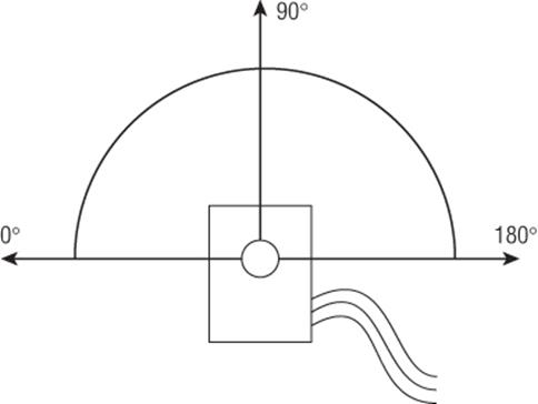
Figure 14.1 Servo motor movement
To know the exact position, servo motors can use a wide variety of techniques. Most use a potentiometer, using electrical resistance to understand how far the arm has turned, while more advanced systems use a coded optical wheel to get precise information.
Servo motors were originally designed in the dark times of war. They were used in radar and anti-aircraft artillery during World War II. Radar requires the angle of the emitter and receiver to be known because the position of the aircraft needs to be calculated and displayed on a screen. Anti-aircraft artillery needs to be placed at a precise angle depending on the results of the calculation, and servo motors could place heavy loads at the right angle much faster than humans and with more reliability.
Although it might seem strange to have a motor that does not make complete turns, servo motors have a wide range of uses. They are used in industrial systems to open and close valves; they are still used on radar or tracking equipment to point a device in the right direction with a high level of precision; and robots use servo motors to keep arms at a precise angle, while providing enough force to keep the arm in place with a high load. Hobbyists making remote controlled vehicles are familiar with servo motors because they are used to control steering. When the front wheels of a car turn left or right, this is a servo-motor acting, keeping the direction in place despite resistive force.
A servo motor is a motor assembly with additional sensors and logic. In short, an embedded microcontroller reads the angle of the output shaft, and controls a small motor.
Controlling Servo Motors
Most motors require only two wires: one for the power and one for the ground. Stepper motors are slightly different, having several wires to move a motor by a specific number of degrees, but still have no embedded intelligence. (Stepper motors are explained in Chapter 15.) Servo motors are different; most require three wires. One wire is for power, one is for the ground connection, and the third one is for sending orders to the servo motor.
Servo motors use pulse width modulation (PWM) to receive instructions. Pulse width modulation uses short and precise pulses of digital signals to transmit information. PWM was first presented in Chapter 4.
A servo expects a pulse every 20 milliseconds. The length of the pulse instructs the servo motor to move to a specific angle. The PWM signals vary between a ½ and 2 ½ milliseconds. A ½ millisecond pulse instructs the servo motor to move to its minimum position, and a 2 ½ millisecond pulse tells the Servo motor to move to its maximum position. A 1 ¼ millisecond pulse will move to the central position.
The question is, “How exactly can this be done in an Arduino?” The PWM interface on an Arduino does not have the same timings as servo motor controls, and it is easy to make a mistake and make a pulse longer than 2 milliseconds. Fortunately, the Arduino abstraction layer makes this extremely easy, requiring only a few instructions.
Most boards allow up to 12 Servo motors to be connected at any one time, with the exception of the Arduino Mega, which can control up to 48 motors. However, this comes at a small price. Using the Servo library automatically disables PWM operations on pins 9 and 10. Again, the Arduino Mega is an exception and can happily use up to 12 Servo motors without interference. Any more than 12 servo motors results in PWM being disabled on pins 11 and 12.
NOTE
In Arduino 0016 and earlier, only two servos were supported, on pins 9 and 10.
Connecting a Servo Motor
Servo motors typically have three wires. The power wire, usually red, is connected to the power rail. The ground wire, usually black or brown, is connected to the ground rail. The third wire, usually yellow or orange, is the signal wire and is connected directly to a digital pin on the Arduino. The Arduino can normally directly supply power to a servo motor, but when using several servo motors, you need to separate the Arduino power supply to the servo power supply to avoid brown outs. Servo motors, even if they do not always act like typical motors, still have a small motor inside and can draw large amounts of current, far more than what the ATmega can deliver.
Before using servo motors, you must import the Servo library. You can do this either by importing the library through the Arduino IDE menu (Sketch ![]() Import Library
Import Library ![]() servo) or by manually typing:
servo) or by manually typing:
#include <Servo.h>
In your software, you must first create a new servo object before issuing instructions. You must create one object per servo motor (or group of servo motors) to control.
Servo frontWheels;
Servo rearWheels;
To tell the Arduino which pins the servo motors are connected to, call attach(), specifying the pin, and optionally, specifying the minimum and maximum pulse size.
servo.attach(pin)
servo.attach(pin, min, max)
By default, Arduino uses 544 microseconds as the minimum pulse length (equivalent to 0 degrees) and 2,400 microseconds as the maximum pulse width (equivalent to 180 degrees). If your servo motor has different settings for a maximum and minimum pulse, you can change the values in attach() by specifying the durations in microseconds. For example, a servo motor that uses a 1 millisecond minimum and 2 millisecond maximum can be configured like this:
servo.attach(pin, 1000, 2000);
From then on, the Arduino automatically calculates the length of the pulse according to the wanted angle but will not issue commands until a function specifically orders the servo motor to move.
Moving Servo Motors
Telling a servo motor to move to a specific angle is easily accomplished using write(). The Arduino will do all the necessary calculations; determining the length of the pulse to generate and sending the pulse on time:
servo.write(angle);
The angle parameter is an integer number, from 0 to 180, and represents the angle in degrees.
If you require precision, you can specify the length of the pulse by using the writeMicroseconds() function. This eliminates the need for calculation by the Arduino and specifies the exact pulse length, an integer, expressed in microseconds:
servo.writeMicroseconds(microseconds);
It does not matter what the original position was, the servo motor automatically adjusts its position. The Arduino does not need to calculate this either; all the intelligence is embedded inside the motor assembly. It does, however, keep the last angle that it was instructed to use, and this value can be fetched with read():
int angle = servo.read()
Remember that servo motors can receive only instructions and not return information. The value returned by read() is the value inside the Arduino. When connecting a servo motor, there is no way to know what position it was in initially. It can be helpful to set a servo motor to a default position before starting your application. (For example, a remote-controlled car should probably have the wheels turn so that they are at 90 degrees; without adjusting the steering, the owner would expect the car to go straight and not at an angle.)
Servo motors and other physical objects take time to get to where you want them to be, so it's considered good practice to give your motor a bit of time to get where it wants to go. Some motors move faster than others, if you're unsure of how much time you'll need, it's best to check your motor's documentation.
Disconnecting
If required, servo motors can be disconnected inside sketches. To disconnect a servo, use detach():
servo.detach()
Subsequent calls to attached() return false, and no more signals will be sent until the sketch calls attach() again.
Servo motors can be attached, detached, and re-attached in software. Sometimes a sketch needs to know the status of the devices connected at that time. To see if a servo motor is connected, you can use attached():
result = servo.attached();
This function returns 1 (or true) if a servo motor has been declared as attached, and 0 (or false) otherwise. Note that this won't tell you if your motor is physically attached or not, just that it is connected in software.
Precision and Safety
Controlling multiple servo motors can be rather processor-intensive, and this can sometimes affect precision if you have a large amount of servos controlled by one Arduino. In extreme cases, slight angular distortion may be visible on servo motors with the lowest angular value. This is often in the range of 1 to 2 degrees.
There are situations in which using servo motors can be a safety issue. If used with robotics, one of the most basic rules of robotics is to never get in the way of a robotic arm. Imagine a robotic arm powered by servo motors that is to place an object in the user's hand. The movement must be precise and not go above or below a certain angle.
Using the Servo library does not stop interrupts. You can still respond to interrupts, and timing functions such as millis() still work, but remember that the end of a servo motor pulse can be lengthened by the time it takes to execute an interrupt handler. If your interrupt handler takes 200 microseconds to complete and is called close to the end of a servo's pulse, in the worst case, the pulse sent to the servo motor can be lengthened by 200 microseconds, meaning that the resulting angle is not what you expected. It will be corrected the next time a pulse is sent, and the servo motor will move to the correct angle. In most applications, this will not be a problem, but just keep this in mind if your application has an absolute limit that must not be exceeded.
Example Application
Servo motors can be used for a variety of projects, from remote controlled cars to robotics. To keep things simple, this section uses a servo motor to create a retro-style thermometer. In the digital age, you might sometimes forget what these devices used to look like. Mercury thermometers are usually long glass objects, with a straight line, but some thermometers are round, and have a hand similar to clocks. A servo motor can be used to move the hand, controlled by an Arduino that gets a temperature reading from an external component, perfect for indoor or outdoor temperature readings.
This example uses an LM35. The LM35 is an inexpensive and readily available precision temperature sensor calibrated in Celsius, and illustrated in Figure 14.2. It can be used to sense temperatures between –55° C and +150° C by adding a resistor and a reference voltage, but without any additional resistor, it can sense temperatures between 0° C and 100° C. The LM35 outputs 10 mV for each degree, from 0 V for 0° C to 1,000 mV (or 1 V) for 100° C.
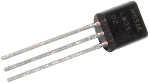
Figure 14.2 An LM35
However, the Arduino's analog-to-digital converters are normally calibrated from 0 to 5 volts, but the LM35 will never output 5 volts. To compare analog values, the Arduino will compare the input to something called a reference—a voltage. Generated inside the microcontroller, this reference is normally set to the same voltage as the Arduino's power. The reference voltage can be changed so instead of sampling values between 0 and 5 volts, the Arduino can be told to sample between 0 and 1.1 volts. You do this by callinganalogReference (INTERNAL). This will give more precision for this application, but it comes at a price. If using the INTERNAL constant, this sketch will not run correctly on an Arduino Mega; it will require changing. When this example is complete, it will be up to you, the designer, to choose if you want to sample on 5 V and keep compatibility or to use a different sample range and only use specific boards.
By using a reference of 1.1 V, the 10-bit ADC will have a sampling precision of 1.1 divided by 1,024, or 1.07 mV. The LM35 outputs 10 mV per degree, so 10 divided by 1.07 is approximately 9.31. So, a change of 9.31 in the analog reading equals 1 degree. To get a reading in Celsius, simply get the return value and divide by 9.31.
The sketch can now retrieve temperatures between 0 and 100 degrees Celsius, but this range is too large. If your internal thermometer is showing 100 degrees, your house might be on fire, and you shouldn't be looking at your thermometer. If the outside reading is 100 degrees, something is wrong. In both cases, there is no use in displaying the temperature, so everything above 50 will be ignored.
Finally, the last part will be to convert a temperature into the servo motor movement. For this example, the servo motor will be mounted so that the 0–180 degrees line is parallel to the floor. Ninety degrees will be straight up. The temperature hand will move only between 45 degrees and 135 degrees.
This brings a question: How should the temperature be converted to an angle? This sounds like a lot of complicated calculation; 0 degrees Celsius is 45 degrees for the Servo motor, and 50 degrees Celsius will be an angle of 135 degrees. The truth is, there is no need to make any calculations; the Arduino will do that for you using map(), explained in Chapter 4. As a reminder, map() works like this:
result = map(value, fromLow, fromHigh, toLow, toHigh);
This function maps a number from one range to another, and that is exactly what is in this example: two ranges. Temperature values vary from 0 to 50, and angles vary from 45 to 135. Therefore, with a single function, the Arduino will automatically calculate the output to the stepper motor, converting a temperature range to an angle range.
Schematic
This application uses an Arduino Uno. The LM35 will be connected to analog pin 0, and the servo will be connected to digital pin 9. The wiring that should be used is shown in Figure 14.3.
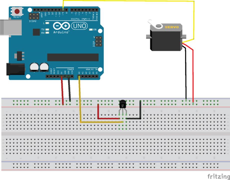
Figure 14.3 Temperature sensor application schematic (Image created with Fritzing)
Sketch
Time to write the sketch, as shown in Listing 14.1.
Listing 14.1: Sketch (filename: Chapter14.ino)
1 #include <Servo.h>
2
3 float tempC;
4 int angleC;
5 int reading;
6 int tempPin = A0;
7 int servoPin = 9;
8
9 Servo thServo;
10
11 void setup()
12 {
13 analogReference(INTERNAL);
14 Serial.begin(9600);
15 thServo.attach(servoPin);
16 thServo.write(90);
17 delay(1000);
18 }
19
20 void loop()
21 {
22 reading = analogRead(tempPin);
23 tempC = reading / 9.31;
24 angleC = map(tempC, 0, 50, 135, 45);
25 Serial.print(tempC);
26 Serial.print(" Celsius, ");
27 Serial.print(angleC);
28 Serial.println(" degrees");
29 thServo.write(angleC);
30 delay(500);
31 }
The work starts right from line 1. On the first line of the sketch, the Servo library is imported. On lines 3 to 7, variables are defined. The temperature is defined as a floating-point number, and all other variables are defined as integers.
On line 9, a Servo object is created, called thServo, short for thermometer Servo. This is the instance on which instructions will be called.
On line 11, the setup function is created. In this function, three things will be done. First, the reference voltage is set to INTERNAL, meaning the analog-to-digital converter will compare against a 1.1 V reference, not 5 volts as it would normally. This works for all analog inputs, and therefore, no pin is specified. Second, a serial interface is created for debugging. Finally, the sketch is told to attach a servo motor on pin 9 (servoPin), and a default value is written. Ninety degrees is specified, moving the arm to a default position in the middle of the reading. The sketch is given 1 second to move, which is more than enough time.
On line 20, the loop() function is defined. First, the sketch reads the voltage from A0 , comparing it to 1.1 V. The result, returned as an integer, is stored in reading. Next, the variable reading is divided by 9.31 (calculated previously), and the result is stored in a floating-point number, called tempC. Next, the angle must be calculated. This is done through map(), by first indicating the values that are expected for the temperature (0 to 50) and next, the values expected as an angle (135 to 45). The numbers are inverted because this servo motor turns counterclockwise, and the lowest temperature is expected to be on the left.
On lines 25 to 28, data is printed to the serial port. This is used as debug information and can be omitted in a final version.
Finally, on line 29, the angle is written to the servo pin, and the sketch waits for one-half a second before repeating.
Congratulations, you have just created a retro thermometer!
Exercises
This sketch is fully functional but requires some tweaking to be optimal. For example, the servo motor movement may sometimes be a little erratic. Now look at the serial output to have a better idea:
22.34 Celsius, 86 degrees
22.77 Celsius, 86 degrees
23.20 Celsius, 88 degrees
So, the difference between 22.77 and 22.34 degrees Celsius does not result in a movement, but the difference between 22.77 and 23.20 degrees Celsius results in a 2-degree movement? This is the result of the map() function, and because it “translates” a 50-unit range to a 90-unit range, it will lose a little precision. If you need more precision, you will have to look at another way of controlling the servo motor. Try using writeMicroseconds() for greater accuracy.
Also, there is one requirement that was not put into place. Temperatures above 50 degrees Celsius should be ignored, but they aren't. map() specifies values between 0 and 50, and will “map” them to values between 45 and 135, but this does not mean that values are limited. If the input value is outside of the input range, it will also be outside of the output range. Try to limit input or output values, using min() and max(), or even better, use constrain().
What solution did you come up with?
Summary
In this chapter, you have seen what a servo motor is and how it differs from typical motors. You have seen how it is controlled, and how to position it as required. In the next chapter, you will see another type of motor—the stepper motor—the functions used to control it, and an example application to put it all together.
All materials on the site are licensed Creative Commons Attribution-Sharealike 3.0 Unported CC BY-SA 3.0 & GNU Free Documentation License (GFDL)
If you are the copyright holder of any material contained on our site and intend to remove it, please contact our site administrator for approval.
© 2016-2026 All site design rights belong to S.Y.A.