Arduino Sketches: Tools and Techniques for Programming Wizardry (2015)
Part II. Standard Libraries
Chapter 15. Stepper
This chapter discusses the following functions of the Stepper library:
· Stepper()
· setSpeed()
· step()
The hardware needed to use these functions includes:
· Arduino Uno
· 1 x L293D
· 1 x 5-V bipolar stepper motor
· Breadboard
· Cables
You can find the code downloads for this chapter at http://www.wiley.com/go/arduinosketches on the Download Code tab. The code is in the Chapter 15 download and the filename is Chapter15.ino.
Introducing Motors
Electric motors generally work by creating electromagnetic fields from coils, forcing magnets on an axle to move, therefore driving the axle. By generating electromagnetic fields, a motor turns continuously until current is removed.
Servo motors (presented in Chapter 14) function a little differently, but even if their usage is different, a servo motor is still controlled by an ordinary electric motor managed by a small microcontroller to ensure the servo motor can move to a precise position.
Stepper motors are different. They have several coils inside, and the internal axle is “toothed.” When applying current to one of the coils, the closest “tooth” is attracted to the coil, and the axle moves by a few degrees. Current is then removed from the coil and sent through another coil, again attracting a tooth and moving the axle by a few degrees. By repeating this operation, a stepper motor can be controlled to turn continuously in either direction, but this is not normally a stepper motor's main function. Stepper motors can have precise movement and as such can drive gears with equal precision.
Imagine a printer. Paper is fed into the printer, and the printer begins to print one line. A print head moves across the paper and deposits ink in precise locations according to the image that was sent to it. When the print head arrives at the far edge of the paper, the paper is fed into the printer, and the printer heads returns in the opposite direction, continuously printing until the end of the page. Feeding paper into the printer is extremely precise; too much paper and white lines appear on the sheet. Too little, and the resulting image will be squashed. The movement has to be precise and feed exactly the right amount of paper. Chances are, the motor feeding the paper into the printer is a stepper motor. Also, because the printer head requires precise positioning, there is a good chance that the belt used to attach the printer head assembly is also controlled by a stepper motor.
Stepper motors have several characteristics, but the most important one is the angle per “step.” This can vary greatly in the different models, but ranges of between 2–5 degrees are common.
Controlling a Stepper Motor
Stepper motors are different from standard electrical motors, and as such, can be difficult to control. They require both software and hardware to be used. Fortunately, the hardware isn't difficult to use, and the Arduino software library is even easier.
Hardware
Stepper motors come in different sizes, and more important, different power ranges. It is common to find 12-V models, but this can be complicated for 5-V systems. Also, stepper motors tend to require higher current than what a microcontroller can provide. For most applications, a microcontroller cannot control a stepper motor directly; it must be interfaced with additional hardware. An H-Bridge is one type of component that can help use a stepper.
An H-bridge is an electronic component (or configuration of transistors) designed initially to control electric motors, as shown in Figure 15.1.
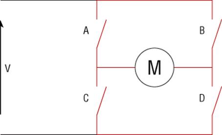
Figure 15.1 An H-bridge driver
By activating A and D, current can flow from the 12-volt rail, through a motor's electromagnet, to ground. This turns the motor in one direction. When activating B and C, the current flows in the opposite direction, and therefore the motor also turns in the opposite direction. This configuration also has the added bonus of allowing the motor to turn freely, by deactivating all inputs, or even to brake the motor by activating C and D.
Because an H-bridge controls one electromagnet and because stepper motors are composed of two or more electromagnet coils driven in sequence, a dual H-bridge can be used to drive a stepper motor. This is achieved by turning on specific coils and giving the motor enough time to align to that coil before turning it off and turning on another coil. By doing this, you can have a motor turn in a precise fashion, a few degrees at a time. The downside is that stepper motors are not as fast as classic motors, but they were not designed for speed. It is still possible to vary the motor speed by changing the frequency of the inputs, and stepper motors can still achieve relatively fast rotation speeds.
Unipolar Versus Bipolar Stepper Motors
Unipolar stepper motors have coils with a center tap, an electrical connection in the middle of the coil. This makes current switching easier; instead of inverting current, the center tap can be used as a grounding point for the current, and one pole or the other can be powered, therefore effectively inverting polarity without the need for complicated electronics. The center taps are often joined together, so these motors often have five leads.
Bipolar motors do not have a center tap; instead, the hardware must be used to invert current. As this inversion is easily achieved with an H-bridge, managing this is no longer a major factor. Bipolar motors do present a major advantage; because they have simplified coils, they can often achieve more torque for the same weight.
NOTE
H-bridge drivers are commonly used for both unipolar and bipolar stepper motors, therefore no longer requiring the center tap, maximizing the torque of unipolar motors.
The Stepper Library
The Arduino IDE has built-in support for stepper motors through the Stepper library. To import the Stepper library, either add the library automatically via the Sketch ![]() Import Library
Import Library ![]() Stepper menu item, or manually:
Stepper menu item, or manually:
#include <Stepper.h>
To begin using a stepper motor, you must create a new instance of the Stepper class.
Stepper(steps, pin1, pin2);
Stepper(steps, pin1, pin2, pin3, pin4);
The steps parameter is an int which indicates the number of steps that your motor must make to complete one revolution. Some motors only document the number of degrees per step; in that case, divide that number by 360 to get the number of steps. The pin1 andpin2 parameters are digital output pins used for two lead stepper motors. The pin3 and pin4 parameters are used for motors with four leads. This is done like so:
Stepper myStepperMotor = Stepper(84, 5, 6, 7, 8);
Stepper motors turn by performing single steps, and to increase the speed of the motor, you must change the frequency at which steps are performed. To do this, use setSpeed():
Stepper.setSpeed(rpm);
This function does not return any data and configures the output sequence to make the motor turn at the specified speed in revolutions per minute. The rpm parameter is a long. The final function is used to instruct the motor to move by a specific amount of steps:
Stepper.step(steps);
This function does not return any data and requires one parameter: steps. The steps parameter is an int and indicates the number of steps to perform. Depending on the wiring, positive values will cause the motor to turn in one direction, and negative values will make the motor turn the opposite direction. This function does not return until the task is complete, and depending on the amount of steps to perform, this can take a long time. During this time, the sketch cannot continue to perform other actions.
Example Project
In this project, you create another thermometer, one that varies slightly from the servo motor example in the previous example. An LM35 temperature sensor will connect to A0. The stepper motor will connect to digital pins 8, 9, 10, and 11 through a double H-bridge. This project is different from the previous because it will not show the exact temperature, but a variation. A stepper motor can maintain its position and provide force to keep the angle correctly positioned. A stepper motor cannot know its exact position; an order is given to move a certain number of steps in one direction or another, but it cannot know if the motor shaft has turned correctly. Maybe there was too much force involved, and the motor couldn't overpower the force. The advantage to this is that stepper motors can be repositioned; you can force the hand into a certain position and then let the motor reposition itself as required. This thermometer will not show the exact temperature, but a variation. The user can reposition the hand into a central position at any time, and by looking at the thermometer moments later, he will know if it is getting colder or warmer.
Hardware
This project uses an Arduino Uno for the control part of the project and an LM35 temperature sensor like in the servo example. It also uses an H-bridge controller and a 5-V stepper motor. Most H-bridges can use higher power motors, but with a less powerful motor the user can change the position of the motor by hand. An illustration of the circuit is shown in Figure 15.2.
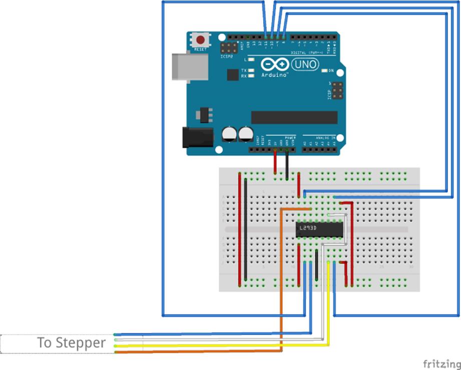
Figure 15.2 Project schematic (Image created with Fritzing)
Stepper motors often have different connections, depending on the make and model. See the documentation that came with your motor to see how to connect it.
Sketch
The sketch is the easy part of the project; this sketch simply reads the temperature and updates the position of the motor depending on temperature differences. The sketch is shown in Listing 15.1.
Listing 15.1: Stepper thermometer (filename: Chapter15.ino)
1 #include <Stepper.h>
2
3 // Set this to the number of steps your motor needs to make one turn
4 #define STEPS 100
5
6 // Stepper motor is connected to pins 8 to 11
7 Stepper stepper(STEPS, 8, 9, 10, 11);
8
9 // the previous reading from the analog input
10 int previous = 0;
11
12 void setup()
13 {
14 // Set a low stepper speed
15 stepper.setSpeed(10);
16
17 // Make a single temperature reading
18 previous = analogRead(0);
19 }
20
21 void loop()
22 {
23 // Get the sensor value
24 int val = analogRead(0);
25
26 // Move the stepper motor depending on the result
27 stepper.step(val - previous);
28
29 // Remember the previous value
30 previous = val;
31
32 delay(5000);
33 }
The Stepper.h file is required for any projects that use the stepper library, and this is included on line one of the sketch. On line 4, the amount of steps required to make a complete revolution is defined. Change this according to the stepper motor you have. On line 7, the Stepper instance is created using the amount of steps defined in STEPS and using digital lines 8 through 11.
setup() defined on line 12 does two things. First, it sets up the speed of the stepper motor to 10 rpm. This is a relatively slow speed, but the motor doesn't need to turn quickly. Secondly, it takes a reading from the temperature sensor to use as a reference value. The value is stored in previous, a variable defined on line 10.
On line 21, loop() is declared. In loop(), you'll first read the value of the analog pin into a variable called val and then change the stepper motor's position by the difference between previous and val. Finally, the contents of previous are replaced by the contents of val, and the sketch waits for 5 seconds before looping.
Summary
In this chapter, you have seen what a stepper motor is, how and where it is used, and how to control one with an Arduino. The example has given you an idea of how easy it is to use a stepper motor, and how you can use them in your own applications. In the next chapter, you will see the Firmata library, a control library that lets you read and write Arduino pins directly from a computer.
All materials on the site are licensed Creative Commons Attribution-Sharealike 3.0 Unported CC BY-SA 3.0 & GNU Free Documentation License (GFDL)
If you are the copyright holder of any material contained on our site and intend to remove it, please contact our site administrator for approval.
© 2016-2026 All site design rights belong to S.Y.A.