Arduino Sketches: Tools and Techniques for Programming Wizardry (2015)
Part II. Standard Libraries
Chapter 17. GSM
This chapter discusses the following functions of the GSM library:
· GSMAccess.begin()
· GSMAccess.shutdown()
· GSM_SMS.beginSMS()
· GSM_SMS.print()
· GSM_SMS.endSMS()
· GSM_SMS.available()
· GSM_SMS.remoteNumber()
· GSM_SMS.read()
· GSM_SMS.peek()
· GSM_SMS.flush()
· GSMVoiceCall.voiceCall()
· GSMVoiceCall.getVoiceCallStatus()
· GSMVoiceCall.answerCall()
· GSMVoiceCall.hangCall()
· GSMVoiceCall.retrieveCallingNumber()
· GPRS.attachGPRS()
· GSMClient.connect()
· GSMServer.ready()
· GSMModem.begin()
· GSMModem.getIMEI()
The hardware needed to use these functions includes
· Arduino Uno
· Arduino GSM Shield
· Active SIM card
· 1 x Reed switch
You can find the code download for this chapter at http://www.wiley.com/go/arduinosketches on the Download Code tab. The code is in the Chapter 17 folder and the filename is Chapter17.ino.
Introducing GSM
One of the many things that defines the human race is our capacity to communicate. Throughout our inventions, we have developed ways to express ourselves, and to talk to more and more people, further and further away. Try to imagine life without a mobile phone, or any sort of telephone. How do you tell someone something? There are still options available to you; you could write a letter (a real letter, not an e-mail, one with pen and paper). It would take a day or two to arrive, and the recipient would read it when he arrived home (or at the office). You could also leave the house to see the person, either by going to her house, business, or a common meeting place (the town square, or even a restaurant). Neither of these options are as fast as dialing them up.
Of course, things do change. When writing this book, I am constantly in contact with my publisher and editor. I pick up my mobile phone, and call a number, and a few seconds later, another telephone rings, separated by a wide distance. I am in Europe, and they are in the United States. No matter where I am, either at home in France, or on a business trip to England, Brazil, or Singapore, people can get ahold of me. The international telephone network connects millions upon millions of people together, at distances that span the entire world, but the ability to place telephone calls is only one aspect of this network.
Mobile Data Network
Long gone are the days when a mobile telephone was used only for placing phone calls. Today, even the most basic of phones can receive network data as either text or multimedia messages. More advanced phones can receive e-mails, browse websites, or even stream high-quality videos through advanced data networks. We can be almost anywhere and still receive Facebook requests and spam messages. Times have indeed changed.
Although this may appear to be simple, it is extremely complicated to achieve. Data is sent through multiple channels, and simply walking around outside can be complicated for the mobile telephone network, as users regularly disconnect from one tower while connecting to a new tower. This is all handled transparently by the telephone and the telephone network, resulting in what appears to be a seamless network. The truth is, at any one moment, a telephone, or device in a mobile network, may not send and receive data.
GSM
The first generation of mobile communications, known as 1 G, was a simple technology that allowed full-duplex voice communication (full-duplex meaning that you could talk and listen at the same time). A simple system, it worked extremely well for people that needed to be on the move and connected continuously. Most 1 G telephones were car phones; relatively large devices that ran on a car's battery, but allowed users to do what the telephones were designed for—talking.
The 1 G network was entirely analog, but was only called 1 G when a new technology was needed; it was then known as the second generation, or 2 G and replaced 1 G.
In 1981, the European Conference of Postal and Telecommunications Administration (known as CEPT) created a new committee, the Groupe Spéciale Mobile, based in Paris. The GSM name would later be known as Global System for Mobile Communication, and its logo would become the de facto standard in almost all countries.
GSM changed quite a few technical aspects; all communications were now digital instead of analog. By using digital technology, communications could be compressed, using less bandwidth, allowing more users access to the network. Because mobile devices were becoming truly mobile and smaller, phone's radio emission strength was reduced, requiring more and more cells to allow communications. Cell towers were now cheap to produce, so this wasn't a problem, as was the cost to pay for safe devices that could be placed in a pocket and used all day.
One of the changes that the GSM specification proposed was something that is still in use: a SIM card. A SIM card contains a unique serial number, operator network information, subscriber information, temporary network information, and two passcodes for the user: the PIN and PUK. By using a SIM card, users can choose their mobile operator, and mobile operators can sometimes “lock” mobile phones to their network.
The original GSM specification did not include data transfer but was rapidly modified to allow SMS messages, just one such method that uses digital data. SMS, short for Short Message System, is a technique to send 160 characters to cell towers or to telephones. Although most people think of SMS messages as “I will be 20 minutes late,” they are also an efficient way of warning people in case of an emergency, and for publicity, taxi reservations, payment systems, or even for proprietary inter-application communication. The number of SMS messages range in the billions per year, and although their use is slowly declining in favor of other messaging systems, in 2013, an estimated 145 billion SMS messages were sent.
SMS is not the only data transfer technique used by the GSM network; two other major systems exist.
GPRS
GPRS, short for General Packet Radio Service, is a packet-based data exchange technique. Although most GSM connections were circuit-switched (meaning that a connection was established and then terminated when the connection was cut), GPRS introduced a packet-switching technique, allowing operators to charge clients by the quantity of data used, and not the time spent transferring data. GPRS is an extension to the GPS 2 G technology, and as such, is often known as 2.5 G. This technology allows theoretical speeds of up to 50 Kbit/s, but true throughput is often limited at 40 Kbit/s.
EDGE
EDGE, short for Enhanced Data rates for GSM Evolution, is an enhancement over the previous GPRS data connection method. With a theoretical max speed of 250 Kbit/s, this norm was soon called 2.75 G by mobile telephone owners. It is still used today as a fallback when other high-speed networks are not available.
3 G
The third generation of mobile networks is a large change from the previous 2 G, and is not compatible with the older systems, but remains a fallback technology for current telephones. 3 G allows for higher data speeds than previous standards, ranging from 2 Mbit/s all the way to 28 Mbit/s.
The 3 G standard was created by the International Telecommunication Union, which is not the same as the GSM committee. 3 G mobile devices can use the 2 G network, but 2 G devices cannot connect to 3 G networks. They must use the older 2 G network, forcing operators to have several systems in place on the same tower.
4 G and the Future
4 G is currently the most advanced technology readily available, with extremely high speeds exceeding 50 Mbit/s. The 4 G standard allows for theoretical speeds much higher than that, but even that isn't fast enough for the future, and work has already begun on the 5 G network. Time will tell just how far the mobile network will progress.
Modems
A modem (short for modulator-demodulator) is a device that can send and receive digital data through an analog carrier. Most veteran computer experts remember modems as the trusty 56-k modem—a device that connected to a computer through a serial port and allowed the computer to connect to the Internet (or a company network) through a telephone line. Where does the 56 k come from? The speed, 56 thousand baud or 56 Kbit/s data rate. If everything went well (which it usually didn't) this meant that users could download data at a blistering 4 to 5 kilobytes per second. Don't laugh; they were fast modems, yet most were slower.
Although the trusty 56-k modems have been mostly replaced by broadband, it is interesting to know how they work. Modems are serial devices, and most were instructed to operate using the Hayes command set: simple ASCII messages instructing the modem to perform specific actions. Most commands start with “AT”, short for Attention. A modem is instructed to configure itself in a specific way, to call a number and to get information using simple text messages. When the connection is made, the modem is switched fromcommand mode to data mode, and from there on, the modem sends each byte of data it receives. It is also possible to change from data mode to command mode again to issue more instructions to the modem (for example, to hang up). Again, this is performed by sending AT commands.
The 56-k modem is indeed a dying technology, but its legacy is still with us and will be for a long time. The AT command idea was so well implemented that most radio peripherals still use them; Bluetooth devices, for example, are configured using AT commands. Bluetooth does not connect through telephone lines, but the modem principle is the same; a digital device transmits digital data over an analog medium—in this case, radio waves. Even the most modern 4 G telephone is also a modem, accepting serial data, transmitting and receiving data over radio waves. GSM devices are exactly the same.
Arduino and GSM
There are multiple ways to connect to devices wirelessly and exchange information: Wi-Fi, Bluetooth, and Zigbee to name but a few. Most of these technologies require the user to create an infrastructure, but there is no wireless infrastructure as extensive and as widely used as the mobile telephone network. Also, Arduinos are small, lightweight, and mobile, making them perfect for mobile network use. A GPS tracker on a car is only useful if it can send information through an existing network, and is useless if it leaves your Wi-Fi zone (which probably happens a lot for a car). However, there is a good chance that your car will go through at least several mobile network cells during its trip, allowing it to send data at will.
Several shields exist to achieve this. Arduino produces its GSM shield, one that comes bundled with a SIM card from Movilforum Telefonica. The GSM shield is unlocked, meaning that it can be used with any mobile operator, but Movilforum Telefonica's service is international, and it has a large partner network, allowing for GSM communication just about anywhere.
GSM shields connect to GSM networks but will not work on 3 G and 4 G networks. Although on a 2 G network, the shield enables you to make and receive telephone calls, send and receive SMS messages, and enables data connectivity.
NOTE
Data connectivity means that you can access the entire Internet, but most mobile operators have their own internal network, meaning that your telephone is not directly visible from the Internet. This adds a level of security to your applications but makes it difficult to “listen” for incoming connections. A GSM device should always initiate a connection and wait for a response.
GSM devices are often power-hungry and usually require an external power supply. USB ports that supply 500 mA cannot keep a GSM shield powered under heavy load; these devices often require a power supply between 700 and 1,000 mA.
To use a GSM shield, Arduino has developed a library to create connections, send and receive data, and even manage the SIM card.
Arduino GSM Library
The Arduino GSM library is available in Arduino 1.0.4 and later. The GSM library is a complex library with multiple header files. It can be imported automatically in the Arduino IDE by going to the menu Sketch ![]() Import Library
Import Library ![]() GSM, but doing this adds a large number of files:
GSM, but doing this adds a large number of files:
· #include <GSM3MobileMockupProvider.h>
· #include <GSM3ShieldV1BaseProvider.h>
· #include <GSM3ShieldV1ModemVerification.h>
· #include <GSM3ShieldV1PinManagement.h>
· #include <GSM3ShieldV1SMSProvider.h>
· #include <GSM3MobileClientService.h>
· #include <GSM3ShieldV1CellManagement.h>
· #include <GSM3ShieldV1MultiServerProvider.h>
· #include <GSM3ShieldV1BandManagement.h>
· #include <GSM3ShieldV1DataNetworkProvider.h>
· #include <GSM3ShieldV1.h>
· #include <GSM3CircularBuffer.h>
· #include <GSM3MobileCellManagement.h>
· #include <GSM3MobileAccessProvider.h>
· #include <GSM3MobileClientProvider.h>
· #include <GSM3SMSService.h>
· #include <GSM3MobileDataNetworkProvider.h>
· #include <GSM3ShieldV1ServerProvider.h>
· #include <GSM3MobileServerService.h>
· #include <GSM3VoiceCallService.h>
· #include <GSM3MobileServerProvider.h>
· #include <GSM.h>
· #include <GSM3MobileVoiceProvider.h>
· #include <GSM3ShieldV1VoiceProvider.h>
· #include <GSM3ShieldV1ScanNetworks.h>
· #include <GSM3ShieldV1ClientProvider.h>
· #include <GSM3ShieldV1DirectModemProvider.h>
· #include <GSM3MobileNetworkProvider.h>
· #include <GSM3MobileSMSProvider.h>
· #include <GSM3MobileNetworkRegistry.h>
· #include <GSM3ShieldV1ModemCore.h>
· #include <GSM3ShieldV1MultiClientProvider.h>
· #include <GSM3ShieldV1AccessProvider.h>
· #include <GSM3SoftSerial.h>
Don't be frightened by the large number of files. For most applications, you can simply include the GSM library #include <GSM.h>.
Because the GSM library is complex, its different usage is separated into classes. There are classes to manage GPRS connections: SMS messages, and voice calls, to name but a few.
GSM Class
The GSM class is responsible for initializing the shield and the on-board GSM device. It is initialized like this:
GSM GSMAccess
GSM GSMAccess(debug)
The debug parameter is optional. It is a boolean and is false by default. If set to true, the GSM device outputs AT commands to the console.
To connect to the GSM network, use the begin() function:
GSMAccess.begin();
GSMAccess.begin(pin);
GSMAccess.begin(pin, restart);
GSMAccess.begin(pin, restart, sync);
The pin parameter is a character array that contains the PIN code for the SIM card connected to the GSM shield. If your SIM card does not have a PIN code, you can omit this parameter. The restart parameter is a boolean and specifies if the modem is to be restarted. By default, this parameter is true, resulting in a modem restart. The sync parameter is a boolean and sets the synchronization to the base station. In a synchronous configuration, the sketch can tell if an operation has completed. In an asynchronous configuration, operations are scheduled, and their result isn't always immediately available. By default, it is set to true. All the return codes listed in this chapter correspond to a synchronous configuration.
This function returns a char indicating the status of the modem: ERROR, IDLE, CONNECTING, GSM_READY, GPRS_READY, or TRANSPARENT_CONNECTED.
This can be used as follows:
#include <GSM.h>
#define PINNUMBER "0000" // SIM card PIN
GSM gsm(true); // Debug AT messages
void setup()
{
// initialize serial communications
Serial.begin(9600);
// connection state
boolean notConnected = true;
// Start GSM shield
while(notConnected)
{
if(gsm.begin(PINNUMBER)==GSM_READY)
notConnected = false;
else
{
Serial.println("Not connected");
delay(1000);
}
}
Serial.println("GSM initialized");
}
To shut down the modem, use shutdown():
GSMAccess.shutdown();
This function does not take any parameters and returns a boolean: true if the modem was shut down and false if the function is currently executing. If this function returns false, it does not mean that the function failed, only that the shutdown operation has not yet completed.
SMS Class
GSM modems can, of course, be used to send and receive SMS messages. To enable SMS message services, use the GSM_SMS class:
GSM_SMS sms;
An SMS message is sent in three steps; first, the destination number is required. Second, the text is entered. Finally, the message is confirmed.
To set a destination telephone number, use beginSMS():
sms.beginSMS(number);
The number parameter is a char array, the telephone number that will receive the SMS message.
To fill in the SMS body, use print():
sms.print(message);
The message parameter is again a char array and contains the message to be sent. Note that SMS messages are limited to 160 characters. This function returns the amount of bytes sent, expressed as an int.
To complete an SMS message and to instruct the modem to send the message, use endSMS():
sms.endSMS();
This function does not take any parameters.
When the SMS message has been assembled, the SIM card is told to send the message as soon as possible. The SIM card coupled with the modem make an autonomous unit which acts independently from the Arduino. Assembling and sending a message through the Arduino API does not guarantee that the message is sent; it is queued to be sent.
Because the device is autonomous, it also receives SMS messages without warning; there is no callback and no interruption. The sketch must periodically poll the GSM shield to see if a message is present. This is done with available():
result = sms.available();
This function returns an int, the number of messages waiting on the SIM card. To begin reading a text message, you must first retrieve the number of the sender, which is done with remoteNumber():
sms.remoteNumber(number, size);
The number parameter is a char array, a memory location where the sender ID will be stored. The size parameter is the size of the char array.
When the sender ID has been retrieved, the next thing you must do is to retrieve the message body. You can do this with read(), which works the same way as with file functions and serial buffers. It reads one character at a time.
result = sms.read();
You can read the entire content of a message with the following code:
// Read message bytes and print them
while(c=sms.read())
Serial.print(c);
SMS messages that have been previously read are marked with a hashtag. To see if a message has been read without actually fetching the first character, you can use peek(). Just like with serial buffers, this function returns the first character but does not increment the index. Subsequent calls to peek() or even read() will return the same character.
if(sms.peek()=='#')
Serial.println("This message has been discarded");
To discard a message, you can use flush():
sms.flush();
This function deletes the SMS at the current buffer index from the modem's memory.
VoiceCall Class
You can use the VoiceCall class to place and to answer voice calls. An Arduino can place voice calls but cannot send voice data without additional hardware. Most shields have an audio input and output port, allowing users to add additional components as required. This can be in the form of a microphone and speaker, or for distress calls, it can also be an electronic component capable of outputting wave audio. The GSM component accepts text instructions and encodes/decodes the audio as required. Instructions include dialing numbers, picking up and hanging up, as well as caller identity functions.
The first thing you must do is create an instance of the GSMVoiceCall class:
GSMVoiceCall vcs;
To place a phone call, use VoiceCall():
result = vcs.voiceCall(number);
The number parameter is a char array and is the telephone number to call. The function returns an int: 1 if the call were placed or 0 if it were unable to call. This can be used as follows:
// Check if the receiving end has picked up the call
if(vcs.voiceCall(phoneNumber))
{
Serial.println("Call Established");
}
Serial.println("Call Finished");
This function places only the call and returns if the call were established. To check on the call status, use getVoiceCallStatus():
result = vcs.getVoiceCallStatus();
This function takes no parameters and returns IDLE_CALL, CALLING, RECEIVINGCALL, or TALKING, which is described in Table 17.1.
Table 17.1 getVoiceCallStatus() Return Codes
|
Constant |
Description |
|
IDLE_CALL |
The modem is idling: no incoming calls, no outgoing calls, and no call in progress. |
|
CALLING |
The modem is currently calling a number. |
|
RECEIVINGCALL |
The modem is receiving an incoming call. |
|
TALKING |
A call has been placed (incoming or outgoing) and communication is established. |
The other end of a telephone call can hang up whenever it chooses (or even when network conditions no longer allow a call to continue), and the Arduino can also instruct the GSM device to hang up with hangCall():
result = vcs.hangCall();
This function takes no parameters and returns an int: 1 if the operation succeeded and 0 otherwise. This function not only hangs up a connected call, but can also hang up on an incoming call.
Arduinos can also receive calls, but the GSM modem does not warn the sketch of incoming calls; the sketch must poll the GSM device with getVoiceCallStatus() when there's an incoming call expected. When an incoming call is detected (when getVoiceCallStatus()returns RECEIVINGCALL), you can retrieve the calling number and decide to accept/refuse the call. To get the incoming telephone number, use retrieveCallingNumber():
result = vcs.retrieveCallingNumber(number, size);
The number parameter is a char array and can store the incoming number. The size parameter is the size of the array. This function returns 1 if the phone number is retrieved, and 0 if it is unable to retrieve the phone number.
To pick up an incoming call, use answerCall():
result = vcs.answerCall();
This function does not take any parameters and returns1 if the call is answered, or 0 if it is unable to answer. Incoming calls can also be refused with hangCall().
GPRS
GPRS is the method used to send and receive data using a GSM mobile device. It does not require an active voice call but does require authentication. When the SIM card has been told to create a connection, it maintains the connection and automatically reconnects if needed. Before using a GPRS connection, you must use the GPRS class:
GPRS gprs;
Then, to initiate a connection, you must use attachGPRS():
grps.attachGPRS(APN, user, password);
This function takes three parameters, all three are char arrays. The APN parameter is the Access Point Name, the name of the connection point between the GPRS network and the Internet. Each GPRS network should have one; check with your SIM card provider for more information. The user and password parameters are optional username and password details that are sometimes required to connect to an APN. Again, the documentation that comes with your SIM card should give more details. Not all providers use the username and password fields; in which case they may be left blank. This function returns the same constants as begin(); it returns GPRS_READY when the connection is established.
if (gprs.attachGPRS(GPRS_APN, GPRS_LOGIN, GPRS_PASSWORD)==GPRS_READY)
Serial.println("Connected to GPRS network");
When the connection to the GPRS network is established, you need to create either a server or a client. A server waits for incoming connections, and a client connects to external servers. A server uses the GSMServer class, and a client uses the GSMClient class. Both work almost the same as an Ethernet connection, with a few differences; the GSM library attempts to be as compatible as possible with the Ethernet library.
CROSS-REFERENCE
The Ethernet library was presented in Chapter 9.
To create a client, that is to say a device that will connect to another Internet device, use the GSMClient class:
GSMClient client;
When that is done, you must connect to a server. To connect to a server, use connect():
result = client.connect(ip, port);
The ip parameter is a 4-byte IP address, and port is an int specifying the port that the sketch wants to connect to. This function returns a boolean: true if the connection is established, and false if the connection fails.
When a connection has been made, you can send and receive data. Sending data is done with print(), println(), and write():
result = client.print(data);
result = client.println(data);
result = client.write(databyte);
These functions are presented in Chapter 9.
To become a server, that is to say a device that will listen to incoming connections, use the GSMServer class:
GSMServer server(port);
The port parameter is an int; it tells the server which port to listen on for connections.
One difference between the GSM library and the Ethernet library is the nature of the connection. GSM connections are sometimes unstable; network coverage may not be available in some locations (for example, inside a building or under a bridge). To know if a command were successfully executed, use the ready() function:
result = client.ready();
This function does not take any parameters and returns an int; 1 if the previous operation has completed, and 0 if it has not (yet) completed.
Many network providers do not allow incoming connections on their network, making it impossible to run servers with the GSM shield. Check with your provider to see if there are any such limitations with your network.
Modem
The modem class is used primarily to perform diagnostic operations on the modem component. To use it, you must use the GSMModem class:
GSMModem modem;
To initialize the modem subsystem, you must first use begin():
result = modem.begin();
This function returns true if the modem subsystem was initialized or false if there was a problem with the initialization. (For example, the shield has not been correctly installed.)
To retrieve the IMEI number, the International Mobile Equipment Identifier, a unique number identifying the shield's modem, use getIMEI():
result = modem.getIMEI();
This function does not take any parameters and returns a String, the IMEI number of the GSM modem.
Example Application
One of the domains where Internet-connected devices are in constant demand is home security. Most security devices use a home's Wi-Fi connection, but these devices are vulnerable to attack. For this reason, many security systems also have a backup GSM system, allowing devices to communicate even if the physical line to the Internet is severed.
For this application, you will create a system that monitors a door or window. In the event of this entrance opening, a warning message is sent via text message. To make sure that the system works, every few minutes a “heartbeat” is sent to an Internet server. This message is just a small bit of information that shows that the system works. If the server does not hear from the Arduino within a certain timeframe, then it knows that something is wrong.
This example uses an Arduino Uno and a GSM shield. One entrance is monitored by means of a reed switch, button, or other contact-based switch. This switch must be configured as NC, normally closed, and connected to the Arduino's ground. Normally this would require a resistor to pull either the 5-V power rail or the ground, but Arduinos have internal pull-up resistors that can be activated in code, and that is what will be done here. If the door is open, the connection is severed, and the Arduino's internal pull-up registers an intrusion. Also, if the wires are cut, theArduino also registers that as an alert. The schematic is shown in Figure 17.1.
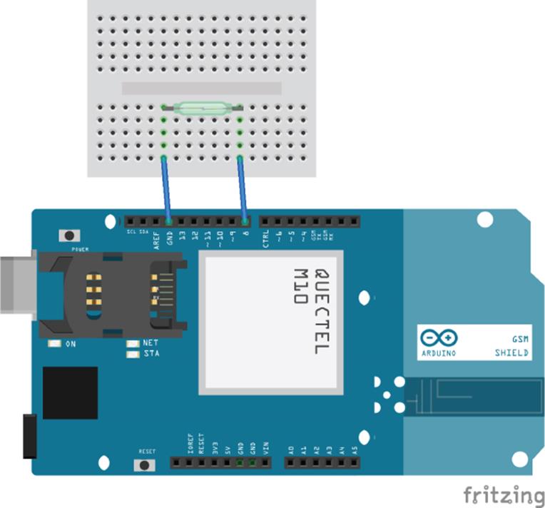
Figure 17.1 Project schematic
Your sketch should look like Listing 17.1
Listing 17.1: Sketch (filename: chapter17.ino)
1 #include <GSM.h>
2
3 #define PINNUMBER "0000" // Replace with your SIM card PIN
4 #define CONTACT "01234567" // Replace with your mobile telephone
number
5 #define GPRS_APN "GPRS_APN" // Replace your GPRS APN
6 #define GPRS_LOGIN "login" // Replace with your APN login
7 #define GPRS_PASSWORD "password" // Replace with your APN password
8 #define SERVER "yourhomesecurity"
9 #define PORT 8080
10
11 // initialize the library instance
12 GSM gsmAccess;
13 GSM_SMS sms;
14 GSMClient client;
15 GPRS gprs;
16
17 // Variables
18 bool intrusion = false;
19
20 void setup()
21 {
22 // initialize serial communications and wait for port to open:
23 Serial.begin(9600);
24
25 // connection state
26 boolean notConnected = true;
27
28 // Start GSM shield
29 // If your SIM has PIN, pass it as a parameter of begin() in
quotes
30 while(notConnected)
31 {
32 if((gsmAccess.begin(PINNUMBER)==GSM_READY) &
33 (gprs.attachGPRS(GPRS_APN, GPRS_LOGIN, GPRS_PASSWORD)
34 ==GPRS_READY))
35 notConnected = false;
36 else
37 {
38 Serial.println("Not connected");
39 delay(1000);
40 }
41 }
42
43 pinMode(8, INPUT_PULLUP);
44 45 Serial.println("GSM initialized");
46 }
47
48 void loop()
49 {
50 for (int i = 0; i < 600; i++)
51 {
52 delay(500); // sleep for half a second
53 if (digitalRead(8) == HIGH)
54 {
55 if (intrusion == false)
56 {
57 // An intrusion has been detected. Warn the user!
58 intrusion = true;
59 sendWarningSMS();
60 }
61 else
62 {
63 // The user was already warned about an intrusion, do
nothing
64 }
65 }
66 else
67 {
68 // Everything looks OK
69 intrusion = false;
70 }
71 }
72
73 // It has been 10 minutes, send a heartbeat
74 if (client.connect(SERVER, PORT))
75 {
76 Serial.println("connected");
77 client.print("HEARTBEAT");
78 client.stop();
79 }
80 else
81 {
82 // if you didn't get a connection to the server:
83 Serial.println("Connection failed");
84 }
85 }
86
87 void sendWarningSMS()
88 {
89 sms.beginSMS(CONTACT);
90 sms.print("Intrusion alert!");
91 sms.endSMS();
92 }
This sketch begins by importing the GSM library, and then defining the necessary parameters for this sketch: the PIN number, the contact number, and different connection parameters.
On line 12, the different objects are created: gsmAccess is used to talk to the Arduino GSM board, sms is the object used to send SMS messages, client is used to create a GPRS client connection, and gprs is used to attach the GPRS connection.
The setup() function is declared on line 20. The serial connection is configured on line 23, and on line 26 the variable notConnected is set to true. As long as this variable is true, a while loop attempts to attach to the GPRS network, with the attachGPRS() function on line 33. Finally, on line 43, pin 8 is set as an input with an internal pull-up resistor.
On line 88 a function is declared: sendWarningSMS(). This function will send an SMS message to the specified contact. The SMS message is created on line 90 using the beginSMS() function. On line 91, text is sent to the SMS engine—this will be the content of the message. Finally, on line 92 the endSMS() function will send the message.
The loop() function is declared on line 49. It starts with a for() loop and iterates 600 times. Each loop will start by waiting for a second, and then looking at the state of the digital input on pin 8. If the result is false, that means that the reed switch has been activated, and the variable intrusion is set to true before calling the sendWarningSMS() function.
Once this loop iterates 600 times, or close to 10 minutes, the sketch will attempt to connect to a server. If the connection is successful, the sketch will send a message to the server telling it that the security system is still up and running. If the sketch cannot connect, then a warning message is sent to the serial console.
The sketch is simple and needs protection. A warning light could be added, or at least an output to a relay for a siren of some sort. Also, the device can send SMS messages to warn people, but it can also receive messages—you can write a routine that can receive messages to turn the security on if the user leaves the house without activating his alarm.
Summary
In this chapter, I have shown you just how flexible a GSM shield can be and the different ways it can be used. You have seen an example using just some of the many functions, and explored an idea about how to increase connectivity. In the next chapter, I will show you the Audio library, a powerful library that adds function to an Arduino Due to output audio files. You will see how audio files are composed and how to create a device that will output audio to a loudspeaker.
All materials on the site are licensed Creative Commons Attribution-Sharealike 3.0 Unported CC BY-SA 3.0 & GNU Free Documentation License (GFDL)
If you are the copyright holder of any material contained on our site and intend to remove it, please contact our site administrator for approval.
© 2016-2026 All site design rights belong to S.Y.A.