Arduino Sketches: Tools and Techniques for Programming Wizardry (2015)
Part III. Device-Specifi c Libraries
Chapter 18. Audio
This chapter discusses the following functions of the Audio library:
· begin()
· prepare()
· write()
The hardware needed to use the examples in this chapter includes:
· Arduino Due
· Ethernet Shield (Arduino, SainSmart, etc.)
· Micro-SD card
· Breadboard
· LM35 Temperature Sensor
· Wires
· 3.5-mm audio jack
· An audio amplifier
NOTE
The Audio library is only found in Arduino IDE version 1.5 and later. It is still considered experimental and under development.
You can find the code download for this chapter at http://www.wiley.com/go/arduinosketches on the Download Code tab. The code is in the Chapter 18 folder and the filename is Chapter18.ino.
Introducing Audio
Science fiction films from the 1980s were full of strange machines with lots of flashing lights and annoying beeps. The first PCs sold had only a buzzer, and the first versions could only do that, buzz. A while later, people played with the buzzer, making tones and even music for games. There are various videos on YouTube that show what games used to be like. Don't laugh; we really did play like that, and we liked it!
The gaming industry was driving sound development at the time, and gamers wanted more advanced music. It wasn't long before MIDI sound cards were released. MIDI is a protocol for connecting musical devices together. (A computer can also be a musical instrument.) Some sound cards could be programmed with “instruments” to be played back at different notes. Although the sound fidelity was much better than the original internal buzzers, it could still be better. Music was certainly much better, but recorded sounds still were not possible—or at least, not easily. You could listen to high-quality music, but the explosions created by your rocket launcher wouldn't sound quite right. The industry turned to another solution.
A new generation of sound cards was born: Creative Lab's Sound Blaster series. It had the features of MIDI sound cards but also had digital signal processors (DSP for short) that could create complex digital audio signals. Computer processors were more and more powerful, and finally powerful enough to create complex sounds by digitally interpreting an analog signal through the sound card. We could hear music, and explosions sounded great. We stayed up all night hurling rockets at each other.
Again, new technology had its benefits but also had a problem: space. Digital sound files took up a lot of space, and space wasn't readily available at the time. High-end hard drives were just more than 1 gigabyte in size, and a 3-minute song recorded from the radio could be hundreds of megabytes in size. If music were to become digital, we needed larger hard drives or to find a way to compress music, preferably both. Today, a song can be compressed into 4 or 5 megabytes and placed onto a music player with gigabytes of space. However, it also requires something else: faster processors.
Digital Sound Files
One of the first digital audio formats is known as wave: an uncompressed digital file that represents an analog signal. Where analog signals can have almost every value possible between their maximum and minimum values, digital cannot. It requires a resolution: the amount of values it can handle. On a scale of 0 to 10, an analog signal would create a 7.42, but a digital signal from 0 to 10 in steps of 1 would not; the closest it can do is 7, as shown in Figure 18.1.
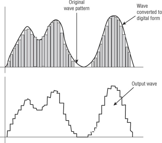
Figure 18.1 Digital resolution
As you can see, the analog signal flows through different values, but the digital representation creates a “step” effect; the representation of the data is not precise, and quality is lost. Thankfully, sound cards do not have values that go from zero to 10; most are 16 bits for a total of 65,536 values. Previous generations had 8-bit sampling for a total of 256 values, and 256 values are too low for an accurate representation. However, the 16-bit value of 65,536 is considered to be more than enough for most audiophiles. This is the quality found on CDs and even some Blu-ray audio files. However, the resolution is not the only factor to take into consideration.
Sound waves are a mixture of different frequencies; the higher the frequency, the higher the pitch. Humans can normally hear sounds from as low as 20 Hz all the way to 20 kHz and above. To digitally sample frequencies as high as 20 kHz, the effective sampling rate (the speed at which the sound is sampled) must be at least doubled or 40 kHz. For typical applications, a sampling rate of 44.1 kHz is used. A microchip was already on the market that used this frequency for sampling, designed by Sony Corporation. For professional applications, sampling was done at rates as high as 48 kHz. 44.1 kHz and 48 kHz are common sample frequencies found on computers, as are multiples of 44.1 kHz; 22.05 kHz, and 11.025 kHz. 8 kHz was used for a long time for telephone systems, where audio quality was adequate to understand human voice conversations. Professional sampling devices can sample at a high rate for even more accurate results; DVD audio is sampled at 192 kHz, and other devices can go as high as 2 MHz.
The higher the sampling rate, the more accurate the result will be. The effects of sampling speed are shown in Figure 18.2.
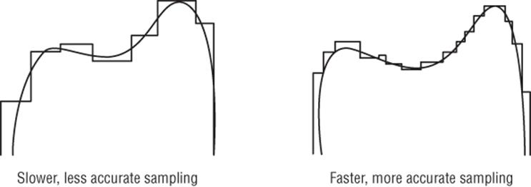
Figure 18.2 Sampling rates
Higher sampling rates also create more data, meaning more space is required.
Music on the Arduino
Arduinos can create musical tones because music is, put simply, repeated frequencies. A musical A has a frequency of 220 Hz, a musical A' is double that, or 440 Hz. By knowing the frequencies of notes, it's possible to program an Arduino to create simple musical tones. For example, the famous song “Happy Birthday” can be written in musical tones as: “CCDCFE CCDCGF CCC1AFED BBAFGF.” By using tone(), you can generate a musical tune to impress your friends, but it remains a simple musical tone. The sound is clearly artificial and does not resemble piano tones or any other musical instrument.
CROSS-REFERENCE
tone() is presented in Chapter 4.
Arduino Due
The Arduino Due is a different kind of Arduino. It is based on Atmel's implementation of an ARM Cortex-M3, a powerful microcontroller and has more processing power than most Arduinos. It is a 32-bit microcontroller, runs at 84 MHz, and has more input and output pins than most Arduinos, including some advanced functions. Audio output on Arduinos is normally done by varying the frequency of a square wave, but the Arduino Due has two Digital to Analog Converters (DAC) that can output a true analog signal, like the pulses produced by tone().
Pulse width modulation is an “all or nothing signal;” the output alternates between a logical high and a logical low. High fidelity sound is different; it requires a signal that has multiple values between the minimum and maximum voltage to control the volume, and to provide a clearer audio signal. The tone() function generates a square wave, but unlike pulse width modulation, it has a 50% duty cycle, that is to say, it oscillates between a logical high and a logical low, both phases being equal in length. It results in an audible tone, but cannot represent a complex audio signal like voice.
CROSS-REFERENCE
PWM is presented in Chapter 4.
Digital to Analog Converters
Digital to Analog Converters (DAC) can be used to generate waveforms and are often used to create sine, triangle, and sawtooth waves. Because these devices can create custom waveforms and because sound is also a waveform, they can be used to create sound—and with relatively good precision.
WARNING
Microcontrollers and DACs can generate signals but are not powerful enough to power devices; they require an amplifier to create a signal powerful enough for a speaker to use. Connecting a speaker directly to the microcontroller can, and probably will, damage the pin, maybe even the microcontroller.
A DAC is the opposite of an Analog to Digital Converter (ADC) but it uses the same properties. A digital signal has a resolution; the amount of bits that are used to create a signal. On the Arduino Due, the two DACs have 12-bit resolutions; they can write values from 0 to 4,095. The analog output varies from one analog value to another; on the Arduino Due, it varies from 0 V to +3.3 V, the voltage of the Cortex-M microcontroller. Because the voltage range is 3.3 V and because there are 4,096 possible values, the DAC has a precision of 3.3 divided by 4,096, or approximately 0.000806. Each increment on the digital side will result in a change of 0.8 mV on the analog side.
Digital Audio to Analog
Digital audio files are essentially a representation of analog signals. It is therefore easy to take each value and to write that value into a DAC, creating a waveform that is close to the original audio. There are several factors to consider:
· Resolution—The resolution of the digital audio file is important; on most computers, they are either 8 bits or 16 bits, but the Arduino Due's DAC has a 12-bit resolution.
· Speed—The original file was sampled at a precise speed, and playing back the audio data at a different speed would change the pitch.
· Stereo or mono—Audio can be recorded as mono (single channel) or stereo (dual channel). The Arduino Due can play only mono files, so stereo files play back as mono; both channels convert to a single channel.
Creating Digital Audio
You can create digital audio files using numerous tools, from programs on your computer to your smartphone. Most operating systems have at least one application you can use to record your voice. Digital audio can also be “converted”; converting one format to another is also possible with a large range of applications, but because some audio formats are licensed, some of these applications are either shareware or commercial.
A third option is the capability of some more advanced programs to “speak” directly, using voice synthesis. This can later be used to create new files containing the voice. This is an interesting solution if you are looking for a robotic voice system.
For most audio recording, limited resources are required. For nonprofessional applications, a simple multimedia headset is often more than enough; some USB models have good sampling rates and offer noise reduction. Try to record your voice inside with no other ambient noises. Choose a time when you know you will not receive a phone call or have a visit from someone. Having a break of even one-half an hour can result in a slightly different voice, so try to record all the files you need in a single session.
Storing Digital Audio
Digital audio files can be extremely large, and wave files are not compressed. For a typical desktop computer, this will not be a problem. Audio CDs containing wave files could hold 80 minutes of stereo music in 700 megabytes, which is normally more than sufficient for most projects. Most audio files can exceed the Arduino Due's internal memory and flash, so another storage medium is required. To store (and play) digital audio on the Arduino Due, you must use an SD card with a shield that has SD-card capability.
WARNING
The Arduino Due is not a 5-V device; it is a 3.3-V device. Some shields that are designed for 5-V Arduinos will not work on the Arduino Due, so check compatibility.
The shield can be any type that supports an SD card; some sensor shields and most Ethernet shields have an SD-slot present on the board. For more information on SD cards, see Chapter 12.
Playing Digital Audio
To play back audio files, you must first import the library: Audio.h.
#include <Audio.h>
To play back Audio files from the SD card, you will also require the SD and SPI libraries; import SD.h and SPI.h.
#include <SD.h>
#include <SPI.h>
NOTE
The Arduino Due is supported only in the versions of the Arduino IDE. Version 1.0 does not support the Due, and you cannot import the Audio library from the menu. Version 1.5 and above support both the Arduino Due and the Audio library.
To initiate the Audio library, you run begin().
Audio.begin(rate, size);
This function takes two arguments: the rate and a size. The audio rate is the number of samples per second; for example, 22050 or 44100 are typical values. For stereo audio files, you must double the audio rate (44100 for 22.05 kHz and 88200 for 44.1 kHz). Thesize parameter indicates the size of an audio buffer that will be created by this function, in milliseconds. For example, to prepare the Arduino Due to play a 44.1-kHz stereo file with a 100-millisecond buffer, use the following:
// 44100Khz stereo => 88200 sample rate
// 100 mSec of prebuffering.
Audio.begin(88200, 100);
When the Audio library is ready, you must prepare your samples to be played. This is done with the prepare() function:
Audio.prepare(buffer, samples, volume);
The buffer parameter is the name of a buffer created by your sketch; it is not the audio buffer created by the begin() function. The samples parameter is the number of samples to write, and the volume parameter is the volume of the audio output, expressed as a 10-bit number; 0 is a silent output, and 1023 is the maximum volume possible.
The final step is to write the data into the audio buffer using the write() function.
Audio.write(buffer, length);
The buffer parameter and the length parameter are identical to the parameters used in the prepare() function. This function writes the samples to the internal audio buffer. If the audio file is not played, playback commences. If the file is currently played, this adds the samples to the end of the internal buffer.
Example Program
For this application, you create a digital thermometer, using an LM35, a small thermometer that is first presented in Chapter 14. The schematic is almost identical, but for this application, there is a change. When the user presses a button, the Arduino does not display the time; it says it out loud.
To do this, you have quite a bit of work to do. The Arduino cannot “speak” directly; to say “The temperature is 22-degrees Celsius,” it requires several sound files. The first part, “The temperature is” will be one file, and the last part, “degrees Celsius” will also be one file. In between, you have to record your voice or get a friend to record theirs. Don't worry; you don't have to record every number between zero and 100; like the previous example in Chapter 14, this application does not go above 40. You can choose later on if you want to go higher. Also, the English language does come to your rescue in this example; every number between zero and 20 will have to be recorded, but after that, it is easier. For example, in the 30s, each number starts with “thirty,” followed by 1 digit. The number 37 could therefore be a file with the word “thirty,” and a file with the word “seven.” This is exactly what your GPS system does in your car; “In four-hundred meters, turn right” is actually composed of several files. It is up to you to create those files or to find some free audio files on the Internet—the choice is yours.
You must decide how to proceed and with the exact wording required. For this example, you create numerous audio files. The first one, called temp.wav, will contain a quick phrase; “The current temperature is” or words to that effect. Afterward, you need to create numerous files; each number from 0 to 20 and named as the number they contain, plus the extension .wav. For example, the file containing the word “18” would be “18.wav.” There is no need to record 21; this will be done by mixing 20 and 1. Instead, record the tens: 20, 30, and 40. For most applications, 40 should be sufficient.
The application itself will be simple, but it is something that you can use to create a nice project. When the user presses a button, the temperature is sampled. One by one, files are opened on the SD card and sent to an audio buffer. When all the files are read, the last file is closed, and the system waits for the user to press the button again.
Hardware
For this example, you will be using an Arduino Due with a shield compatible with the board that has an SD slot. The Ethernet shield used in Chapter 9 would suffice, even if the Ethernet adapter is not used; this application needs only the SD-card slot. The LM35's output will be connected to analog input 5, and the ground pin will be connected to the ground pin on the Arduino Due, but the +Vs pin is different. On previous examples, it was connected to the +5V pin because that is all that was available. However, the component's documentation states that the +Vs pin must have at least 4 V, but the Arduino Due is powered only by 3.3 V. On the Arduino Due, there are two voltage pins: 3.3 V and 5 V. For this example, the LM35 will be powered by the +5-V pin. For other components, this might have been a problem; the Arduino Due is powered at 3.3 V, and the inputs expect to have 3.3 V or lower; applying 5 V to an input could damage the microcontroller. The LM35, however, can safely be powered by +5 V in this application because the output is equivalent to 10 mV per degree Celsius, or 1.5 V for 150 degrees. Therefore, the LM35 can safely be powered by +5 V because it will not output more than 3.3 V.
The button will be connected to digital pin 2. It will be powered by 3.3 V and connected to ground through a 10-Kilohm pull-down resistor. When the button is open, the input will be connected to the ground, resulting in a logical zero. When the button is pressed, the input will be connected to 3.3 V, resulting in a logical 1.
Finally, the audio output will be connected to DAC0. Remember, this is only a signal; it is not strong enough to power a speaker. Using too much power will result in damage to the Arduino. To output audio, the schematic uses a jack connector. Most home Hi-Fi systems or mobile speakers use a jack input, usually by using a male-to-male jack cable. It uses the same connecter you would use to connect your MP3 player to the speaker.
Figure 18.3 shows the layout for this design.
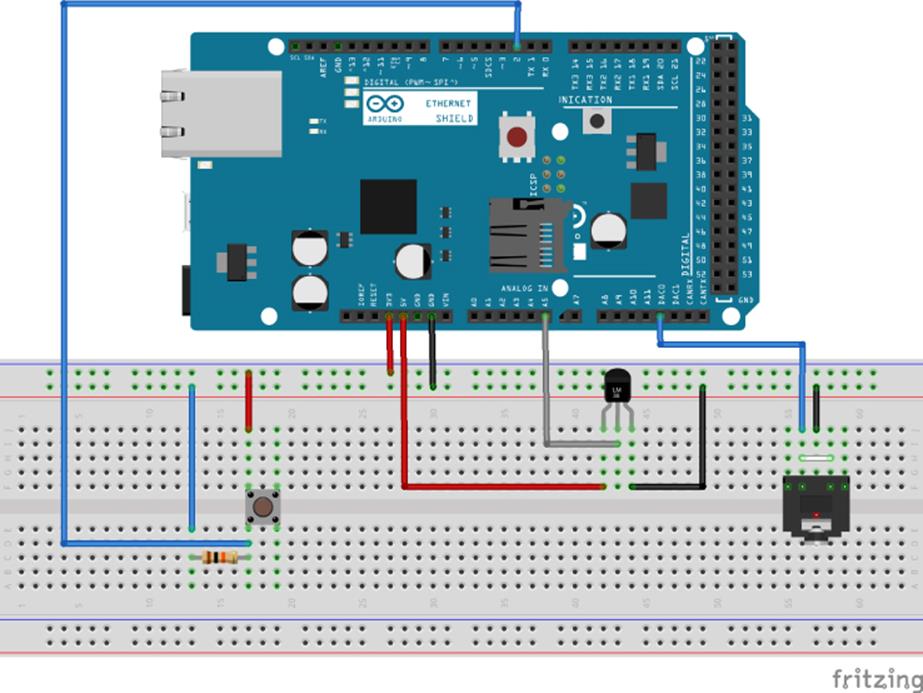
Figure 18.3 Hardware layout (Image created with Fritzing)
Sketch
The code that will be used for this sketch is presented in Listing 18.1.
Listing 18.1: Sketch (filename: Chapter18.ino)
1 #include <SD.h>
2 #include <SPI.h>
3 #include <Audio.h>
4
5 const int buttonPin = 2; // The pushbutton pin
6 const int sensorPin = A5; // The analog input pin
7
8 void setup()
9 {
10 // Debug output at 9600 baud
11 Serial.begin(9600);
12
13 // Set up SD-card. Check your board for the pin to use
14 if (!SD.begin(4))
15 {
16 Serial.println("SD initialization failed!");
17 return;
18 }
19
20 // Configure high-speed SPI transfers
21 SPI.setClockDivider(4);
22
23 // 44100Khz mono files, 100 mSec of prebuffering.
24 Audio.begin(44100, 100);
25
26 // Configure pins
27 pinMode(buttonPin, INPUT);
28 pinMode(sensorPin, INPUT);
29 }
30
31 void loop()
32 {
33 // Wait for a button to be pressed
34
35 if (digitalRead(buttonPin))
36 {
37 // read the value from the sensor:
38 int sensorValue = analogRead(sensorPin);
39
40 Serial.print("Sensor reading: ");
41 Serial.print(sensorValue, DEC);
42
43 // Convert the temperature (3.3V on the Due)
44 int tempC = ( 3.3 * analogRead(sensorPin) * 100.0) / 1024.0;
45 Serial.print(" Temperature: ");
46 Serial.println(tempC, DEC);
47
48 // Play the first file
49 playfile(String("temp.wav"));
50
51 // File name to read?
52 if (tempC > 20)
53 {
54 Serial.print("Open filename ");
55 String filename1 = String(String(tempC - (tempC % 10))
56 + ".wav");
57 Serial.println(filename1);
55 playfile(filename1);
59
60 Serial.print("Open filename ");
61 String filename2 = String(String(tempC % 10) + ".wav");
62 Serial.println(filename2);
63 playfile(filename2);
64 }
65 else
66 {
67 Serial.print("Open filename ");
68 String filename = String(String(tempC) + ".wav");
69 Serial.println(filename);
70 playfile(filename);
71 }
72 }
73 else
74 {
75 // Button was not pressed, sleep for a bit
76 delay(50);
77 }
78 }
79
80 void playfile(String filename)
81 {
82 const int S=1024; // Number of samples to read in block
83 short buffer[S];
84 char chfilename[20];
85
86 filename.toCharArray(chfilename, 20);
87
88 // Open first wave file from sdcard
89 File myFile = SD.open(chfilename, FILE_READ);
90 if (!myFile)
91 {
92 // If the file could not be opened, halt
93 Serial.print("Error opening file: ");
94 Serial.println(filename);
95 while (true);
96 }
97
98 // Loop the contents of the file
99 while (myFile.available())
100 {
101 // Read from the file into buffer
102 myFile.read(buffer, sizeof(buffer));
103
104 // Prepare samples
105 int volume = 1023;
106 Audio.prepare(buffer, S, volume);
107 // Feed samples to audio
108 Audio.write(buffer, S);
109 }
110 myFile.close();
111 }
This sketch has three main functions: the usual setup() and loop()but also playfile(), the function that will be called to play audio files.
setup() is declared on line 8. The serial port is configured on line 11, and the SD card reader is initialized on line 14. Communication between the Arduino and the SD card controller is done via the SPI protocol, and reading wave files requires high-speed transfers. To do this, on line 21, the SPI clock divider is defined to speed up communications. On line 24, the Audio library is initialized. It will expect mono files with a bit rate of 44.1 kHz, and allocates a buffer for 100 milliseconds, more than enough for most data reads from the SD card. Two pins are then defined on lines 27 and 28; the pin used to read the state of the button is set as an input, and then the sensor pin is also defined as an input.
loop() is declared on line 31. This is where most of the work will be done. On line 35, the state of the button is read. If the button is not pressed, almost all of loop() is skipped, and the sketch pauses for 50 milliseconds on line 75 before repeating.
If the button is pressed, then the analog value on the sensor pin is read and stored as a variable. To help debugging, the value is displayed over the serial port. On line 44, a calculation is made, converting the reading from the sensor to degrees Celsius. Remember that the Arduino Due is a 3.3-V device, and therefore, the analog value is compared to 3.3 V, not to 5 V. The temperature is then output to the serial port.
To save space on the SD card, the recording of the different numbers have been separated into different files. If the temperature is below 21 degrees, then a single filename will be used; put simply, the filename is the temperature. If the temperature is eighteen degrees, it refers to a file called “18.wav”. Temperatures of 21 degrees and more will cause two files to be called; one containing the 10s, and one containing the single 1s. Twenty-four degrees will cause the sketch to call two files: “20.wav” and “4.wav”. After the filename is created, playfile() is called with the filename passed as a String.
playfile() is declared on line 80. It takes a single parameter, a String, the name of the file to be opened. On line 82, a const int is declared, which is the amount of data to be copied from the wave file per pass. On the next line, a buffer is created; this is the container where data will be placed from the file on the SD card. On line 84, another variable is created; this is again the filename, but as a char array; the SD.open() function does not accept strings, only chars.
On line 89, the sketch attempts to open the file on the SD card. If it fails, it prints out a message on the serial port and then halts execution. If the sketch does open the file, it carries on.
On line 99, a while loop is created, and loops until there is no more data left to read in the file. This is done with the File.available() function, which returns the number of bytes that can be read from the file. On line 102, the file is read in blocks of sizeof(buffer) intobuffer. On line 105, a variable is declared and contains the value 1023. This is used on the next line, where the Audio library prepares the samples with the Audio.prepare() function. It takes the local buffer called buffer, the size of that buffer, and the volume to be applied; in this case, 1023, or the highest volume possible. The final step is to write the local buffer into the Audio buffer with the function Audio.write(). This function takes the same parameters as the Audio.prepare() function, with the exception of the volume. When the while loop is finished, the file is closed, and the function returns.
Exercise
This application measures the temperature from a single source. You could modify the sketch to retrieve the temperature from an inside sensor, as well as the temperature from outside. You could also add a humidity sensor or an ultraviolet sensor. By pressing a button, you could know that the outside temperature is 38-degrees Celsius, the humidity is 20 percent, and the UV index is 8, but inside you have a comfortable 24 degrees.
Not everyone uses Celsius; you could modify the sketch to use Fahrenheit, and even use the EEPROM to store your setting, making this a sketch that you can use worldwide. You could even create your own shield with sensor connectors, an SD slot, and an audio jack integrated directly onto the shield.
Summary
In this chapter, you have seen how the Due has some advanced functions that can be used to play back audio files, and the library used to perform these actions. You have seen how to wire an Arduino Due to a loudspeaker to create your own alarm clock, temperature sensor, or any sort of device that requires an audio output. In the next chapter, I will show you the Scheduler library, an advanced library for the Arduino Due that allows you to run different tasks at different times.
All materials on the site are licensed Creative Commons Attribution-Sharealike 3.0 Unported CC BY-SA 3.0 & GNU Free Documentation License (GFDL)
If you are the copyright holder of any material contained on our site and intend to remove it, please contact our site administrator for approval.
© 2016-2026 All site design rights belong to S.Y.A.