The Arduino Inventor's Guide (2017)
1 Getting Started with Arduino
This project covers everything you need to get your Arduino up and running! We’ll introduce the hardware, show you how to install the programming environment, and help you make sure everything works by loading a simple program. At the end, you should have your own blinking light and the excitement to move on. Let’s go!
MATERIALS TO GATHER
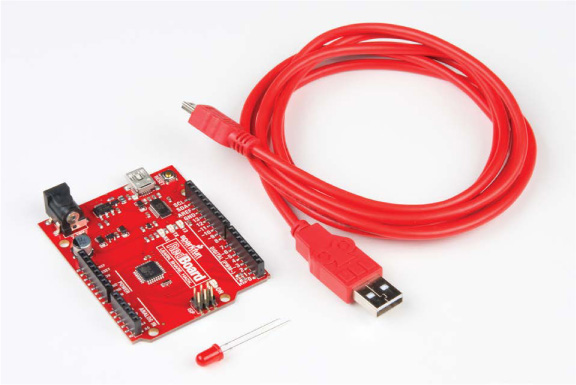
You’ll need the following hardware (shown in Figure 1-1) to complete this project:
• One SparkFun RedBoard (DEV-13975), Arduino Uno (DEV-11021), or any other Arduino-compatible board
• One USB Mini-B cable (CAB-11301 or your board’s USB cable)
• One LED (COM-09590, or COM-12062 for a pack of 20)
FIGURE 1-1: Required components
ABOUT THE ARDUINO
An Arduino (pronounced är·də’wēn·ō or “arr-dween-oh!”) is a small programmable device that can add smarts to nonintelligent things. You can use an Arduino to run robots, create LED art, and even act as a handheld gaming console. In this section, we’ll go into more detail on what the Arduino is and how it can change the way you think about the world around you.
An Accessible Hardware Platform
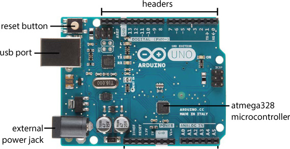
An Arduino is like a small computer. You can program it using very simple instructions, and you can power it with just a few AA batteries. What makes an Arduino really different from a regular computer is that it uses a microcontroller, rather than a CPU, to process information and take action. This small chip acts as the brains of your project, and it can receive input from sensors (like light detectors, temperature sensors, or buttons) and output signals to control LEDs, motors, buzzers, and more. An Arduino board like the one in Figure 1-2 has all of the supporting components and circuitry to make a micro-controller work.
FIGURE 1-2: The Arduino Uno is an open source, programmable electronics platform for hobbyists.
The programming language used for the Arduino is essentially a version of C/C++. The programming environment is the Arduino IDE (integrated development environment). The team that developed it bundled it with many prewritten functions and libraries to simplify the process of writing code to interface with hardware. For example, these libraries take the multiple lines of code required to turn on an LED and simplify them into a single instruction!
About the SparkFun RedBoard
There are many officially Arduino-branded boards, but since the platform is open source (meaning the source hardware design and software are available for anyone to look at and modify), there are also many Arduino derivatives, clones, and compatible boards. The board designs are all licensed under a Creative Commons Attribution Share-Alike license, and the Arduino FAQ (https://www.arduino.cc/en/Main/FAQ) states that anyone is “free to use and adapt [these designs] for your own needs without asking permission or paying a fee.” Derivative boards work with the same programming environment as an official Arduino, but often the hardware has been tweaked or modified in some way.
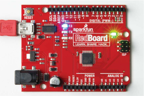
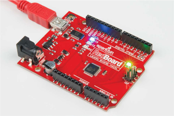
The SparkFun RedBoard, pictured in Figure 1-3, is an Arduino-compatible derivative board. It is based on the Arduino Uno design but has a more stable USB interface and uses a USB mini connector instead of the Type-A connector. Otherwise, it is exactly the same as the Uno, with the same size and shape.
FIGURE 1-3: The Arduino-compatible SparkFun RedBoard. Notice how its shape matches up with the Arduino Uno in Figure 1-2.
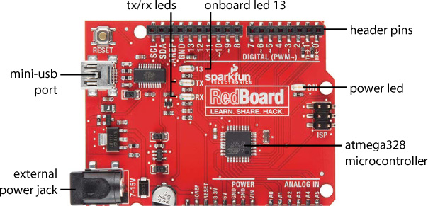
The RedBoard is the go-to Arduino board here at SparkFun and has a few key components that you’ll need to know in order to navigate the first few chapters of this book. We have labeled each term for you in Figure 1-3.
ATmega328 microcontroller The square black chip in the middle of the board. It is the brain of the Arduino.
Header pins The tiny metal legs on the microcontroller, which let you read input and send output. They are accessible through the four sets of black headers on either side of the Arduino. They are numbered and labeled for specific uses. The pins you’ll care about most are those labeled Digital (0–13), Analog In (A0–A5), and Power.
Mini-USB port This is how you send code to and communicate with the Arduino. You can also power your board using the USB port for most applications in this book. If an external power supply is needed, we’ll be sure to point it out.
Power LED This LED is an indicator to show that the Arduino is powered on. If you ever have a short circuit on your board or a bad power connection, this indicator will not turn on.
TX/RX LEDs These LEDs blink when data, such as code or numbers, is being passed back and forth between your Arduino and your laptop.
Onboard LED 13 A debug light. If you’re plugging your Arduino in for the first time, LED 13 should blink once per second. It’s connected to pin 13 on the Arduino.
External power jack A barrel jack port next to the USB port. The Arduino takes 5 V of power, though you can safely supply the Arduino a voltage between 7 and 15 V without damaging your board. A chip on the Arduino scales this input voltage down to 5 V for the electronics and circuitry to work properly.
Like all Arduino-compatible boards, you’ll program the RedBoard with the Arduino IDE.
INSTALLING THE ARDUINO IDE AND DRIVERS
You should install the Arduino IDE before plugging your RedBoard into the USB port for the first time. To install the Arduino IDE, go to http://www.arduino.cc/download/. Select the appropriate version for your computer’s operating system, and click the link to download (Figure 1-4). You’ll be asked whether you’d like to make a contribution; the development and maintenance of the Arduino IDE rely on the help and contributions of the community that uses it.
NOTE
If you’ve already plugged in your board, that’s not a problem—you may just need to restart your computer after the installation is complete for the drivers to work properly.
FIGURE 1-4: You can use the online IDE or download the latest version for your operating system.
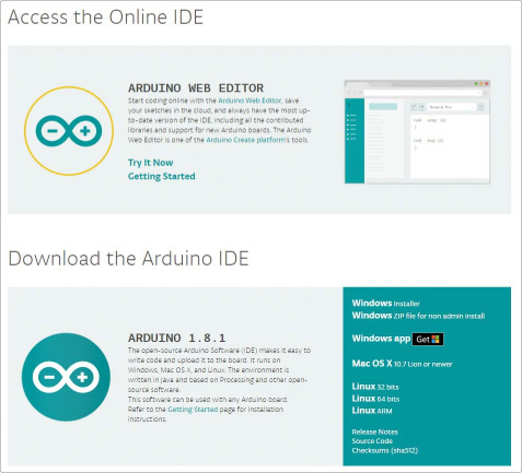
Even if you already have the IDE installed, we recommend downloading and installing the latest version. The Arduino IDE is continuously being updated and improved, and it’s best to have the newest release. The examples in this book use IDE versions 1.8.1 and later.
NOTE
If you like to be on the bleeding edge of software, the Arduino Downloads page also provides nightly builds that preview the next release. For this book, however, we recommend using the latest stable release.
The Arduino website also provides an online platform called Arduino Create, which includes a web-based code editor. It allows you to program your device through your web browser and share and view projects with others online. As of the writing of this book, it is supported only on Windows and OS X.
Whether you choose to use Arduino Create or the downloaded IDE, follow the directions online to run the installation process.
Installing on Windows
If you’re working on a Windows PC, we recommend downloading the Windows Installer version of Arduino. Download this file, open it, and click Run. This will bring up the Installation Options dialog (Figure 1-5).
FIGURE 1-5: Installation Options dialog for Arduino. Make sure that USB drivers are selected!
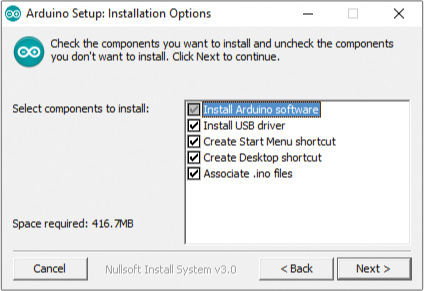
Check the Install Arduino software box along with the other options, or you’ll have to install the drivers separately. Then, tell the installer where you’d like to install Arduino (we recommend accepting the default directory), and click Install.
Once you begin the installation process, have a snack or a cup of coffee, because it could take a few minutes to complete. Depending on your version of Windows, you might again be asked if you want to install drivers and if Arduino LLC is trusted, as pictured in Figure 1-6.
FIGURE 1-6: In Arduino we trust!
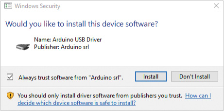
If you don’t want to see prompts like this again, check the box that says you trust Arduino. Either way, click Install to install the USB drivers. That’s it! Arduino typically installs a shortcut on your desktop. Double-click that now to run the Arduino IDE.
Installing on OS X
If you’re using a Mac, download the Arduino IDE option for OS X, and follow the directions in this section.
Installing the IDE
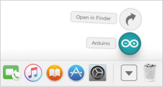
After the download is complete, hover your cursor over your Downloads folder, and click Open in Finder as shown in Figure 1-7.
FIGURE 1-7: After downloading, the program will be in the Downloads folder. Click Open in Finder to move it into the Applications folder.
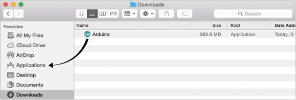
Then, simply click and drag the Arduino program file into the Applications folder, as shown in Figure 1-8. In most cases, you won’t need to install anything else, and you should be able to open the Arduino IDE as you would any other program.
FIGURE 1-8: Click and drag the Arduino file into the Applications folder on the left.
Installing the FTDI Driver Manually on OS X
If you’re using a standard Arduino Uno board, the drivers should be preinstalled and work out of the box. If you’re using the SparkFun RedBoard, there’s one extra step needed to manually install a driver. The SparkFun RedBoard uses a USB chip from Future Technology Devices International (FTDI) to communicate with your computer. You need to manually install the FTDI driver for this chip. First, navigate to http://www.sparkfun.com/ftdi/. This will take you to our tutorial on installing FTDI drivers (see Figure 1-9).
Click the link for Mac OS X. This will direct you to options for a driver to install based on the version of OS X running on your computer. There is one option if you have Mac OS X 10.3 (Panther) to 10.8 (Mountain Lion) and another option if you have Mac OS X 10.9 (Mavericks) or greater.
FIGURE 1-9: SparkFun FTDI Installation Guide

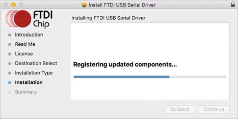
Download the appropriate driver and double-click it to start the installation process. You should be greeted with the familiar Mac software install window. Select your hard drive once it is found, and click OK. Continue through the installation process, and when the progress bar fills up (as in Figure 1-10), the drivers should be installed.
FIGURE 1-10: Installation of the FTDI drivers on OS X
That’s it! Now, double-click the Arduino icon in your Applications folder to run the IDE. If you’ve already opened the IDE before installing the FTDI drivers, you’ll need to fully exit and close out of the Arduino IDE and restart it for your serial ports to show up correctly.
NOTE
If you encounter an error after driver installation, check out solutions at https://www.sparkfun.com/macdriver/.
Installing on Linux
Arduino is available for Linux users, too. Download the correct Linux file for your system; it comes in 32- and 64-bit flavors. Then, uncompress the file using xz-utils or another file compression utility. If you want to use the latest version of Arduino in Linux, you may need to install some other dependency programs as well. Go to http://playground.arduino.cc/Learning/Linux/ for distribution-specific information on this.
For most distributions of Linux (including Ubuntu, Debian, and Fedora), you should be able to use the apt-get package manager to install Arduino from the command line. Open a terminal and enter the following command:
sudo apt-get install arduino
Once the process is complete, open the Arduino program you just installed. Arduino uses Java to run the IDE and must be run out of an XWindows or comparable window user interface environment.
NOTE
Depending on the package manager for your distribution of Linux, the version you install this way may not be the latest version currently hosted on the Arduino site.
A BRIEF IDE TOUR
The IDE is a place for you to write instructions for your Arduino and test them out. These instructions form a program, or in Arduino terminology, a sketch. The IDE allows you to upload your sketch to your Arduino and control things in the physical world.
If you haven’t done so already, open your newly installed Arduino program. After a splash screen, you should see the IDE, which looks something like Figure 1-11.
FIGURE 1-11: The Arduino IDE
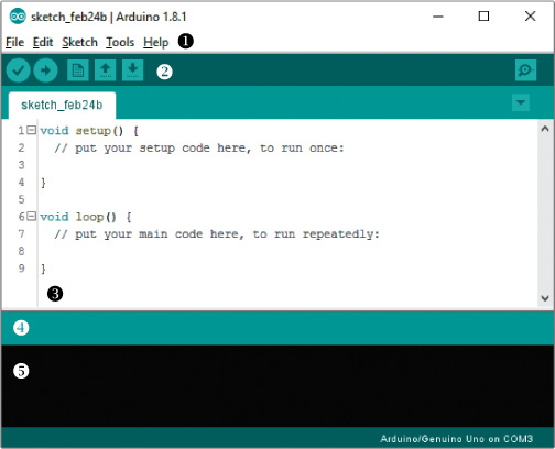
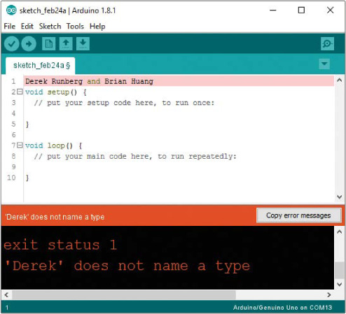
You can use the menu bar (which consists of File, Edit, Sketch, Tools, and Help menus) ➊ to open or save files, upload your code to the Arduino, modify settings, and so on. You should also see a set of graphic buttons ➋. In order from left to right, these are Verify/ Compile, Upload, New, Open, and Save. We will explore those menus and buttons throughout this book. The majority of the IDE is whitespace ➌; this is where you’ll write your code. Underneath the code area is the alert bar ➍, and below it you’ll find the console ➎; these report statuses, alerts, and errors. For example, if there’s a typo in your sketch (called a syntax error), the IDE will show you the error there. If you try typing your name in the code window and click the check mark (Verify/Compile) button, the Arduino IDE will think for a bit and then show an error in the alert bar, highlight your name, and give you more information in the console about the error, as you can see in Figure 1-12.
FIGURE 1-12: A typical error message and readout in the Arduino IDE
CHANGING THE DEFAULT PREFERENCES
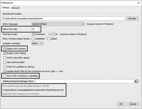
Arduino is a fully open and configurable programming environment. There are a few minor things we like to tweak in the preferences to make it easier to write code, debug, and make cool stuff. Select File ▸ Preferences to view and change the general settings of the Arduino IDE. You should see a window similar to Figure 1-13.
We suggest adjusting the editor font size so it’s comfortable for you to read. We also like to check Display line numbers and uncheck Save when verifying or uploading. Line numbers will help you navigate around your code easier, and unchecking the auto-saving feature will allow you to quickly test code without having to save it each time. Arduino is completely open, so if you want to, you can also click the preferences.txt file and adjust many other features.
FIGURE 1-13: Arduino Preferences window
TEST DRIVE: PLUGGING IN THE ARDUINO FOR THE FIRST TIME
When you have the Arduino IDE and drivers fully installed, connect your Arduino board to the USB port of your computer using the appropriate cable. The power LED should turn on, and if your board is completely new, you should see an LED, labeled 13, blinking as in Figure 1-14. Your computer is powering the Arduino board through the USB cable, and it’s running code that was installed at the factory. Unlike a computer, an Arduino can only store and run a single sketch at a time. The standard test sketch loaded onto an Arduino is a simple LED blink. With your board plugged in, you’ll set up the IDE so that you can write your own sketch.
NOTE
If you plugged in your board before installing the IDE and drivers, you may need to restart your computer.
FIGURE 1-14: The LED labeled 13 blinks when you power a new board.
Choosing Your Board in the IDE
Depending on your computer or operating system, it may take a little bit for the computer to identify the new hardware you just plugged in and associate it with the drivers you installed. After your computer recognizes the new device, click Tools and mouse over the Board option, as in Figure 1-15.
FIGURE 1-15: The Board selection list in the Tools menu
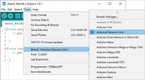
A list of pre-supported Arduino boards should appear. If you’re using a standard Arduino Uno or the SparkFun RedBoard, select the option Arduino/Genuino Uno. If you end up using a board other than an Uno or RedBoard in the future, select the correct Arduino based on your board’s documentation—this book assumes that you’re using the Uno or an Uno derivative.
Selecting the Communication Port
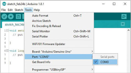
Each device that’s plugged into your computer has a unique communication port identifier. You need to configure the IDE so that it knows which port your Arduino is connected to. To do this, first select Tools ▸ Port to see the communication port options for your device. You’ll see different options depending on your operating system.
On Windows
If you’re using a Windows PC, you may see COM3, COM4, or another numbered COM port, as shown in Figure 1-16. Select this option. If no options show up, see “Basic Arduino Troubleshooting” on page 27.
FIGURE 1-16: Selecting the communication port on Windows
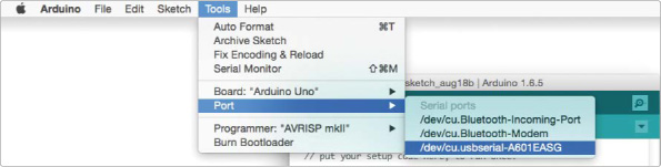
On OS X and Linux
On Mac or Linux machines, the communication port should be listed as /dev/cu.usbserial-A<xxxx>, where the <xxxx> is a string of random characters unique to your Arduino. Select this option. You may see more than one port listed, as in Figure 1-17, but only the one with this unique ID string will map to your Arduino. If no options show up, see “Basic Arduino Troubleshooting” on page 27.
FIGURE 1-17: Selecting the communication port on OS X
AN ARDUINO “HELLO, WORLD!”
“Hello, world!” is the classic first program that many beginning programmers write. In most other programming languages, this program displays Hello, world! to the screen. Because the Arduino doesn’t have a screen, its version of “Hello, world!” is a blinking LED.
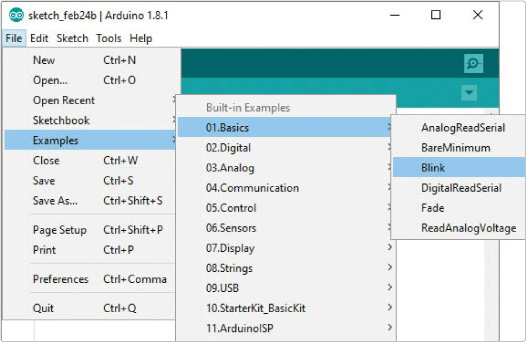
For your first sketch, we’ll show you how to use an example that comes with the Arduino IDE. With your board connected to your computer, click the File drop-down menu and select Examples ▸ 01.Basics ▸ Blink as shown in Figure 1-18 to open a sketch called Blink.
A new IDE window containing the Blink sketch should open. In this window, click Sketch ▸ Upload or click the Upload icon. The IDE will turn this relatively human-readable code into 1s and 0s that the Arduino understands (a process called compiling) and then upload the sketch to your board.
FIGURE 1-18: Finding the Blink sketch
After you click Upload, watch the alert area for status messages. It should say Compiling sketch… and show a progress bar. After the compiling is complete, your computer will start to upload the sketch to your Arduino. The RX (receive) and TX (transmit) LEDs on your Arduino board should blink rapidly, indicating that the sketch is being transmitted to the Arduino board. The TX light blinks because you’re transmitting something to the Arduino, and the RX light blinks because as the Arduino receives the sketch, it responds to your computer to confirm receipt. When the upload process is done, the status area on the IDE should say Upload complete, and the LED labeled 13 on your board should blink, as in Figure 1-19.
FIGURE 1-19: Turning on LED 13
If you get any error messages, your Arduino might not be talking to your computer. Read the next section, “Basic Arduino Troubleshooting,” for some common problems to look out for, and then try uploading the sketch again.
BASIC ARDUINO TROUBLESHOOTING
The Arduino, like any other programmable piece of electronics, is temperamental at times. Here are a few troubleshooting tips for when you have trouble programming your Arduino.
1. Make sure that your Arduino is plugged into your USB cable and that the cable is plugged into your computer all the way. It’s easy to have the cable only partially plugged into the board. You can also try unplugging it and plugging it back in.
2. Always confirm the board selected in the Board menu is the board plugged into your computer. For our examples, we will have Arduino/Genuino Uno selected.
3. Confirm that the correct communication port is selected in the Tools ▸ Port menu; it should have a checkmark or dot next to it. If you’re not sure which port goes with your Arduino, unplug your USB cable from your computer, refresh the communication port listing, and watch to see which port disappears.
4. Make sure you didn’t accidentally type some stray characters into your example sketch. The code will not compile if there are any extra characters.
5. On Windows, check your computer’s Device Manager. Make sure that there isn’t an exclamation mark next to the device. If there is, you need to reinstall the drivers manually.
6. If you’re still getting error messages, reinstall the drivers for your board. We have additional instructions available at www.sparkfun.com/ftdi/.
These six tips are solutions to common speed bumps for anyone new to Arduino, so start here. If none of these suggestions solves the issue, just stay calm, be patient, and remember that you’re not the first one to have a problem. If you get completely stuck, look for solutions on the official Arduino forum at http://forum.arduino.cc/.
ANATOMY OF AN ARDUINO SKETCH
In this section, we’ll walk you through the Blink sketch that you uploaded to the Arduino in ‘An Arduino “Hello, World!”’ on page 25. First, Listing 1-1 gives the sketch itself, in all its blinky glory.
LISTING 1-1: The Blink example sketch
➊ /*
Blink
Turns an LED on for one second, then off for one second,
repeatedly.
Most Arduinos have an onboard LED you can control. On the
UNO, MEGA, and ZERO, it is attached to digital pin 13;
on the MKR1000 it's on pin 6. LED_BUILTIN is set to the
correct LED pin independent of which board is used.
If you want to know which pin the onboard LED is connected
to on your Arduino model, check the Technical Specs of
your board at https://www.arduino.cc/en/Main/Products
This example code is in the public domain.
modified 8 May 2014
by Scott Fitzgerald
modified 2 Sep 2016
by Arturo Guadalupi
modified 8 Sep 2016
by Colby Newman
*/
//the setup function runs once when you press reset or
//power the board
➋ void setup() {
//initialize digital pin LED_BUILTIN as an output
pinMode(LED_BUILTIN, OUTPUT);
}
//the loop function runs over and over again forever
➌ void loop() {
digitalWrite(LED_BUILTIN, HIGH); //turn the LED on
//(voltage level is HIGH)
delay(1000); //wait for a second
digitalWrite(LED_BUILTIN, LOW); //turn the LED off
//(voltage level is LOW)
delay(1000); //wait for a second
}
When writing sketches in Arduino, you need to be very specific with the words, punctuation, and capitalization you use. These elements are part of a programming language’s syntax. For the IDE to compile your sketch properly, you must use words that it recognizes. These are called keywords, and you’ll notice them when they change to a different color, such as orange, teal, or green. Now, let’s look at some of the features used in this first sketch in detail.
Key Sketch Elements
At the top of the sketch, you declare a new global namespace ➊. This is a space that describes what the sketch does and often includes other information such as variable initializations and library statements. Nearly every sketch will include a namespace. This sketch’s namespace has comments written to help human readers understand what the sketch does. In the Arduino IDE, comments are gray. Every comment either starts with the characters // or is bounded by the symbols /* and */ if the comment is longer than a few lines. Notice that not all comments come between lines of code; some appear on the same line as the code they clarify. This doesn’t affect the sketch, because comments are ignored by the IDE. Unlike with code, you can write anything you want in the comments using regular words, spelling, or punctuation.
The skeleton of any sketch consists of two main function definitions, setup() ➋ and loop() ➌. A function is simply a way of grouping multiple instructions or lines of code together. Each function has a data type, a name, and a group of instructions. The word before the function indicates the type of data the function will return. Both setup() and loop() have the type void because they do not return any values.
The name of every function includes a set of parentheses. These parentheses are where you pass parameters to the function. Parameters are values that a function needs to do its job. Neither setup() nor loop() needs parameters, but you’ll use some functions in later projects that do need them. Finally, the lines of code that make up the function are grouped by an opening curly bracket, {, and closing curly bracket, }.
The setup() and loop() functions are required for every Arduino sketch; when the Arduino is turned on for the first time or is reset, the setup() code runs once and only once, and loop() code repeats continuously over and over. It’s like baking cookies: instructions in setup() get out all of your tools and ingredients, and loop() bakes batches over and over until you turn off the oven (that is, the Arduino).
Now, let’s figure out what each line of code in setup() and loop() is actually doing.
The setup() Function
First, let’s take a closer look at the Blink sketch’s setup() function; see Listing 1-2.
LISTING 1-2: The setup() code for our Blink example
void setup() {
//initialize digital pin LED_BUILTIN as an output
pinMode(LED_BUILTIN, OUTPUT);
}
The only line of code inside the setup() function is a call to the pinMode() function. Pins 0–13 on the Arduino are considered general-purpose input/output (GPIO) pins. They can be used as either inputs or outputs, and pinMode()allows you to tell the Arduino how you plan to use a digital pin. You do this by passing two parameters. The first is the pin number, and it can range from 0 to 13. The second parameter is the pin configuration.
For the pin reference, the Blink sketch uses a system constant called LED_BUILTIN to specify that you’re using the default LED on the device. On most Arduino devices, this is the same as pin 13. Notice that the value is in all caps and colored dark teal. This color indicates that LED_BUILTIN is a special keyword with a predefined value used in the IDE.
The second parameter defines the pin configuration as an OUTPUT. Notice that the keyword OUTPUT is also dark teal because it is another constant used in Arduino. There are a few other choices here, which we’ll cover in detail in Projects 4 and 9, but for now just note that Blink sets the pin as an OUTPUT for the LED.
If you were to describe this line of code as a sentence, it would say, “Tell pin 13 to output from the Arduino.”
NOTE
The pinMode() function follows a capitalization convention called camel case. In camel case, the first letter is lowercase, and any later letters that start words are capitalized.
The very last character in the pinMode() call is a semicolon (;), which marks the end of a line of code. When you start writing your own sketches, always end a finished line of code with a semicolon. If you forget one, don’t worry; nearly everyone who’s ever programmed forgets a semicolon eventually, so the Arduino IDE will show a handy warning to help you figure out where to put the missing punctuation.
WHERE’S THE MAIN() FUNCTION?
If you know a bit of programming or are familiar with C or C++, you might wonder where the main() function is in Arduino sketches. When you click Verify/Compile or Upload, Arduino actually pulls together a lot of other files behind the scenes—including a file called main.cpp. Dig around the Arduino program folder, and you can find all the nitty-gritty details of what’s going on. Remember, it’s open source!
Here’s a snippet of code from the main.cpp file:
int main(void)
{
init();
initVariant();
#if defined(USBCON)
USBDevice.attach();
#endif
➊ setup();
for (;;)
{
➋ loop();
if (serialEventRun) serialEventRun();
}
return 0;
}
See where the setup() function is called at ➊? And notice that the loop() function ➋ is inside a forever loop; Arduino implements a forever loop using an empty for(;;). That’s how it runs continuously.
The loop() Function
Now let’s look again at the loop() function, which executes each instruction from top to bottom and repeats itself forever. See Listing 1-3.
LISTING 1-3: The loop() code for the Blink sketch
void loop() {
digitalWrite(LED_BUILTIN, HIGH); //turn the LED on
//(voltage level is HIGH)
delay(1000); //wait for a second
digitalWrite(LED_BUILTIN, LOW); //turn the LED off
//(voltage level is LOW)
delay(1000); //wait for a second
}
The digitalWrite() function allows you to turn the Arduino pins on or off; this is called controlling a pin’s state. This function also uses two parameters. The first indicates the pin you want to control; in this case, we’re using the system constant LED_BUILTIN again. The second parameter is the state you want the pin to be in. To turn the light on, the Blink sketch passes in HIGH. To turn the light off, it passes in LOW.
The second instruction is delay(), which delays your sketch by the number of milliseconds you pass as its parameter. The Arduino Uno and derivative boards like the SparkFun RedBoard execute 16 million instructions per second; that’s really fast! It’s so fast, in fact, that without a delay, you’d never notice a change in the LED. The delay lets us control how long the LED stays on. In the example, delay(1000) instructs the Arduino to delay for 1,000 ms before executing the next command.
The next two lines of code are similar to the first two; they simply instruct the Arduino to turn the LED off and delay another 1,000 ms. After the last line, the loop() function repeats from the top and turns the LED back on.
HACK THE (HELLO) WORLD
One of the best ways to learn from example code is by changing what it does. Try decreasing the delays to 500. Click Upload. How did the blink change? What if you pass delay() the number 5 instead? This is a 5 ms blink! Can you see it? What is the fastest blink rate that you can see?
Your First Piece of Hardware
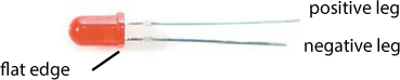
With the LED on your board working and blinking away, the next step is to add your first piece of hardware: an external LED. As we mentioned, the pins on the Arduino are used for hooking up inputs and outputs to the microcontroller, and we can demonstrate that simply with an LED. Grab an LED and take a close look at it. It will look something like Figure 1-20.
You’ll notice that the LED has a short leg and a long leg. If you look really closely, you’ll also see that the edge of the LED bulb has a flat surface on the same side as the short leg. These help you identify the polarity of the legs; the LED’s long leg is the positive leg, and the short leg on the side of the flat bulb surface is the negative, or ground, leg.
FIGURE 1-20: An LED showing the long and short legs
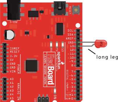
Remember that LED_BUILTIN refers to pin 13 on the Arduino. So, adding your LED to the Arduino is as simple as plugging the long leg of the LED into pin 13 and the short leg of the LED into the GND (ground) pin right next to pin 13. Insert the LED now, with your board powered. If you plug it in correctly, as shown in Figure 1-21, the LED will start blinking. If the LED doesn’t blink, you probably have it plugged in backward. Not to worry: pull it out and flip it around.
FIGURE 1-21: An LED added to pin 13 the quick and dirty way
GOING FURTHER
Each project in this book will have a “Going Further” section, which describes ways to take the concepts you learned in that project to the next level. These sections will include advice on using the existing project, hacking the code, and modifying the project physically.
Hack
For this project, we suggest you try to create some nifty blink patterns. First, copy and paste the four lines in the loop() function so that it repeats and you end up with eight lines of code. This gives you two blink sequences and more code to work with. You can create patterns by modifying the delay times to control when the LED lights. For example, we made a pattern that looks like a heartbeat; our modified Blink sketch is shown in Listing 1-4.
LISTING 1-4: Example code of a heartbeat pattern
void setup() {
pinMode(LED_BUILTIN, OUTPUT);
}
void loop() {
digitalWrite(LED_BUILTIN, HIGH);
delay(200);
digitalWrite(LED_BUILTIN, LOW);
delay(200);
digitalWrite(LED_BUILTIN, HIGH);
delay(200);
digitalWrite(LED_BUILTIN, LOW);
delay(800);
}
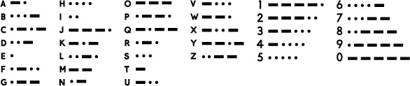
For a real challenge, try programming your Arduino to flash the letters of your name in Morse code with a series of short (dot) and long (dash) blinks. Figure 1-22 shows a Morse code cheat sheet to help you figure out the blink patterns. The classic message that most people start with is S-O-S, or . . . - - - . . . (dot dot dot, dash dash dash, dot dot dot).
FIGURE 1-22: Basic Morse code chart
Modify
A blinking light is a powerful thing! With your newfound superpower, you can physically add LEDs to a lot of things around the house. A Halloween costume is always a great place for some blinky bling. You could solder the LED legs to some wire to make the connections longer so it’s easy to hide the Arduino somewhere more comfortable for the wearer (like in a pocket). We took a Halloween spider we got from the local grocery store and hacked it with some creepy red eyes that blink (see Figure 1-23).
Another good fit for blinking and controlling LEDs is in scale modeling. Adding working LEDs to car headlights, buildings, or streetlights is always a great way to create the illusion of reality in any scale model or scene, as shown in Figure 1-24.
FIGURE 1-23: A blinky scary spider
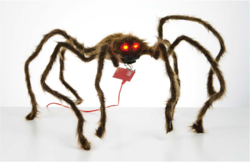
FIGURE 1-24: A scale model with Arduino-controlled lights

SAVING YOUR SKETCH
Every project looks more stylish with a few blinking LEDs, so we suggest you keep your remixed Blink sketch handy so you can reuse parts of it in future builds. Save your sketch, and be sure to name it something descriptive that’ll remind you what it is. Your filename should not contain any spaces; if it does, Arduino will replace the spaces with underscore (_) characters. By default, when you save your sketches, Arduino will save them to the Arduino sketchbook folder, usually found in the Documents folder on your computer. You can choose to save them elsewhere, but it’s often a good idea to have all your sketches in one place.
When you’re ready to level up your blinking skills, head to Project 2, where we’ll show you how to build your very own Arduino-powered stoplight.
All materials on the site are licensed Creative Commons Attribution-Sharealike 3.0 Unported CC BY-SA 3.0 & GNU Free Documentation License (GFDL)
If you are the copyright holder of any material contained on our site and intend to remove it, please contact our site administrator for approval.
© 2016-2026 All site design rights belong to S.Y.A.