The Arduino Inventor's Guide (2017)
2 A Stoplight for Your House
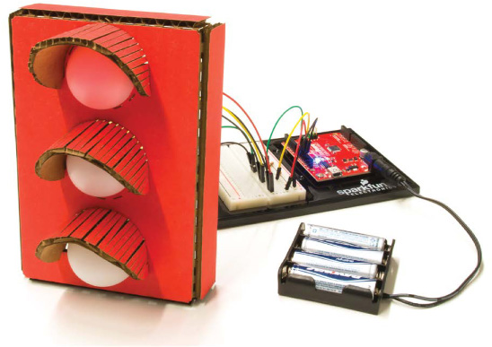
In your first big step toward world domination through embedded electronics, you set up the Arduino IDE and blinked an LED. That’s huge, but with an Arduino, no project needs to stop at just one LED. This project will show you how to expand your first LED sketch to display a blinking pattern on three LEDs. Your mission, should you choose to accept it, is to build and program a stoplight for a busy hallway in your house (see Figure 2-1).
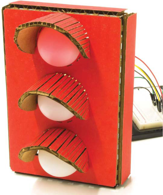
FIGURE 2-1: The completed Stoplight project
MATERIALS TO GATHER
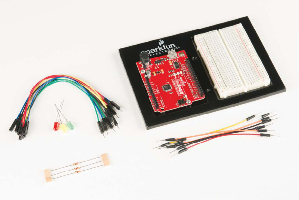
The materials in this project are all pretty simple. All of the electronic parts are standard in the SparkFun Inventor’s Kit, except for the ones marked with an asterisk (*). If you’re using your own kit or piecing together parts yourself, see the following parts list. Figure 2-2 shows all of the parts used in this project.
Electronic Parts
• One SparkFun RedBoard (DEV-13975), Arduino Uno (DEV-11021), or any other Arduino-compatible board
• One USB Mini-B cable (CAB-11301 or your board’s USB cable; not shown)
• One solderless breadboard (PRT-12002)
• One red LED, one yellow LED, and one green LED (COM-12062)
• Three 330 Ω resistors (COM-08377, or COM-11507 for a pack of 20)
• Male-to-male jumper wires (PRT-11026)
• Male-to-female jumper wires (PRT-09140*)
• (Optional) One 4 AA battery holder (PRT-09835*; not shown)
FIGURE 2-2: Components for the Stoplight
Other Materials and Tools
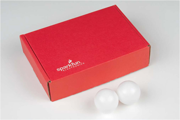
If you want to build an enclosure like the one in Figure 2-1 or follow the suggestions in “Going Further” on page 64, you’ll also need the following supplies, shown in Figures 2-3 and 2-4:
• Pencil
• Craft knife
• Metal ruler
• Pliers
• Wire stripper
• Glue (hot glue gun or craft glue)
• (Optional) Drill and a 3/16-inch drill bit
• (Optional) Soldering iron
• (Optional) Solder
• (Optional) Helping hands (not shown)
• Cardboard (about 12 inches square) or a cardboard box
• Two ping-pong balls
• Enclosure template (see Figure 2-15 on page 55)
NOTE
Good, clean cardboard will be worth its weight in gold in these projects. We suggest picking up cardboard sheets from a craft or art supply store.
FIGURE 2-3: Recommended tools
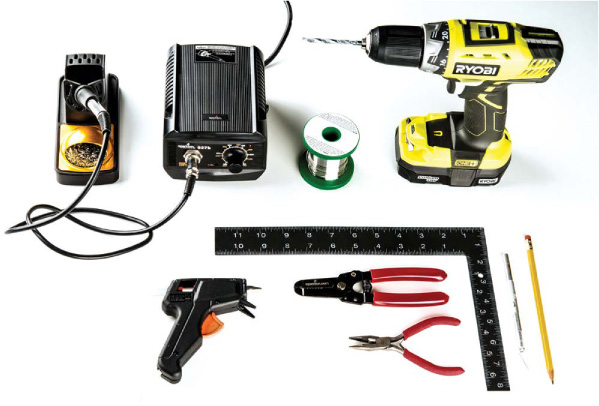
FIGURE 2-4: Recommended building materials
NEW COMPONENT: THE RESISTOR
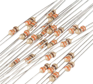
Although you used an LED on its own in Project 1, in most cases it’s best to use a resistor to protect the LED from too much current. Resistors like the ones in Figure 2-5 are everywhere. They are indispensable when you’re building circuits, and you’ll need them to complete this project, too.
FIGURE 2-5: Resistors up close and personal
If you think of electricity like the flow of water through a pipe, a resistor is analogous to a point where the pipe size narrows, reducing the water flow. (If you’re curious, see “Visualizing Electricity as Water in a Pipe” on page 4, which describes this metaphor in detail.) Resistors control or limit the flow of current.
Resistance is measured in ohms (typically shortened to Ω, the Greek symbol omega), and the colored bands on resistors represent their resistance. You’ll find a resistor color band decoder in “Resistors and Bands” on page 308; however, in this book, you only need to be able to identify two different values of resistors: 330 Ω and 10 kΩ. The bands on a 330 Ω resistor are orange, orange, and brown (see Figure 2-5), while on a 10 kΩ resistor they’re brown, black, and orange. There is also a fourth band on a resistor, and its color indicates the resistor’s tolerance. A resistor’s value will be accurate within a certain tolerance: silver means the resistor has a 5 percent tolerance, while gold indicates a 10 percent tolerance. The projects in this book aren’t sensitive enough for the tolerance level to make a difference, though, so we’ll just refer to the resistors by their assumed value, which will work for either tolerance band.
Some components, like LEDs, can be damaged if the current flowing to them is too high, and resistors can protect those components by reducing the current. Having a resistor in line with an LED to limit the current to a safe level is a good precaution so your LED doesn’t burn out—or, in the worst case, pop! (Yes, they can literally pop.) From here on, we’ll use current-limiting resistors in all projects.
WHY THE STOPLIGHT USES 330 Ω RESISTORS
An average red LED has a maximum current rating of about 20 mA, as listed on its datasheet. In order to protect it, you need to add a resistor to keep the current below this limit. But how do you know to use a 330 Ω resistor?
The output pins on the Arduino provide 5 V when they are turned on. Depending on the color, each LED needs a slightly different amount of voltage to turn on, typically in the range of 2.0 to 3.5 V. A red LED turns on at about 2 V, and that leaves 3 V remaining. The 3 V will be dissipated across a resistor or anything else that is in line in the circuit. It’s generally good practice to limit the current going through an LED to about half the maximum, so for the red LED with a maximum current rating of 20 mA, you get 10 mA. You can calculate the resistor needed for 3 V and 10 mA with Ohm’s law (remember 10 mA = 0.01 A):
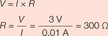
But 300 Ω isn’t a standard resistor value. The closest standard resistor value is 330 Ω, and usually the nearest standard resistor is good enough. This should ensure that the LED lasts for a very, very long time. Since the resistor will be dictating the current, this is a current-limiting resistor.
If you have different resistors available, you could use a different value resistor and see what happens. Bigger resistors will make the current smaller, and smaller resistors will make the current bigger. What happens if you use the 10 kΩ resistor instead?
BUILD THE STOPLIGHT PROTOTYPE
Now it’s time to build the circuit. First, take a look at the schematic shown in Figure 2-6. You’ll build this on a breadboard, as shown in Figure 2-7.
FIGURE 2-6: Schematic diagram for the Stoplight project
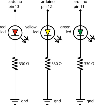
The schematic illustrates how each component is connected electrically. Pin 13, pin 12, and pin 11 on the Arduino will each be used to control an individual LED on the Stoplight circuit. As you can see in the schematic, each LED is connected to an individual resistor, and each resistor is connected to GND (ground). Next, let’s look at the wiring.
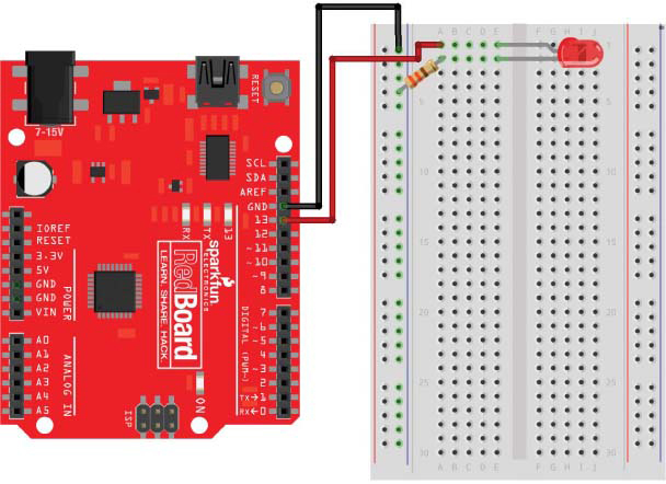
FIGURE 2-7: Connecting a red LED to a breadboard with a current-limiting resistor
Connect the Red LED to the Breadboard
Now you’ll start to translate the schematic into an actual circuit. In the first project, you blinked an LED built into the Arduino board. This LED was internally wired to pin 13 on the Arduino. Because you’ll be using three discrete LEDs, you need to wire these up yourself. Take out your breadboard, and, following the schematic in Figure 2-6 or the illustrated diagram in Figure 2-7, connect pin 13 to the positive (long) leg of the LED.
NOTE
For a refresher on how breadboards work, see “Prototyping Circuits” on page 6.
To wire this on the breadboard, we suggest that you first position your Arduino and breadboard as shown in Figure 2-7. (This will be the standard layout throughout the book.) Then, find a red LED and a 330 Ω resistor. Bend the resistor legs as shown in Figure 2-8 so that the resistor is easier to insert into the breadboard. We suggest using wire cutters to trim both resistor legs by about half their length to make the resistor easier to work with. Resistors aren’t polarized like LEDs, so you don’t have to keep track of which leg is positive or negative.
FIGURE 2-8: Bending a resistor
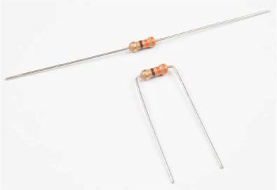
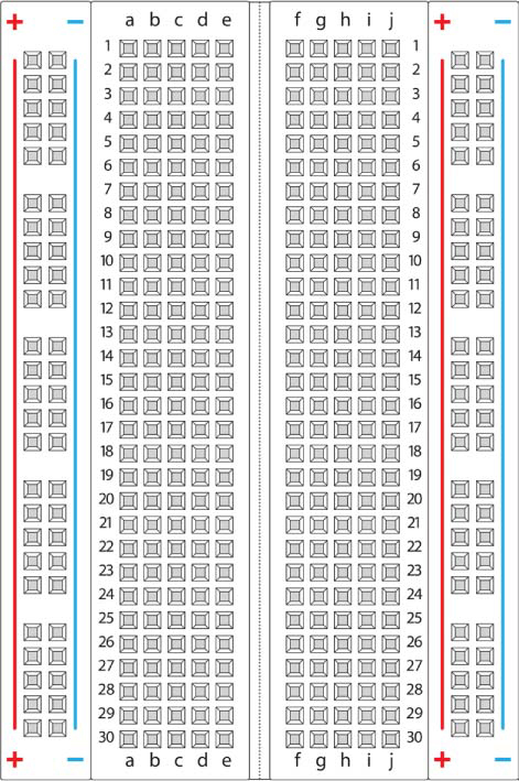
Figure 2-9 shows a diagram of a typical breadboard. Most breadboards have labeled columns and numbered rows as references. Using these reference points, insert the LED into your breadboard as shown in Figure 2-7. The long, positive leg (anode) should be in column E, row 1 (E1) on the breadboard, and the short, negative leg (cathode) should be in column E, row 2 (E2). Now, find a 330 Ω (orange-orange-brown) resistor. Insert one leg of the resistor into any hole in row 2 of the breadboard to connect the resistor to the short leg of the LED. In our diagram, we insert this leg of the resistor into A2 on the breadboard. On all standard breadboards, for each row, columns A–E are connected, and columns F–J are connected. Now, insert the other leg of the resistor into the breadboard’s negative power rail, which is the column marked with a blue or black line and a – (minus) symbol.
FIGURE 2-9: A breadboard has numbered rows and columns labeled with letters.
Add Power to the Breadboard
Grab two male-to-male jumper wires. We suggest using black for ground (GND) and red for power, and that’s the convention we’ll follow throughout this book.
Connect the black wire from the GND pin on the Arduino to the negative power rail on the breadboard. There are three pins labeled GND on the Arduino. You can use any of these. The power for each LED will actually come from the digital pins. Since pin 13 will power the red LED, connect a wire from pin 13 on the Arduino to A1 on the breadboard.
Plug your Arduino board into your computer using a USB cable, and the “Hello, world!” sketch from Project 1 should run, causing your LED to blink. In fact, both the LED on the breadboard and the LED on the Arduino should be blinking, because they’re both wired into pin 13.
If the breadboard LED doesn’t blink but the Arduino one does, double-check your wiring and the orientation of the LED. Make sure that the shorter leg is in the second row of the breadboard, connected to the resistor, and that the resistor is connected to GND through the negative power rail. After you get the red LED blinking, disconnect the Arduino from the computer so that you can safely build the rest of the circuit. It’s best practice to disconnect the board while building your circuit.
Add the Yellow and Green LEDs
Now, connect the yellow LED to pin 12 on the Arduino and the green LED to pin 11; you can follow the same basic instructions you followed for the red LED, but use different pairs of rows for each new LED, as in the final wiring diagram in Figure 2-10.
FIGURE 2-10: The final Stoplight circuit, using pins 11, 12, and 13
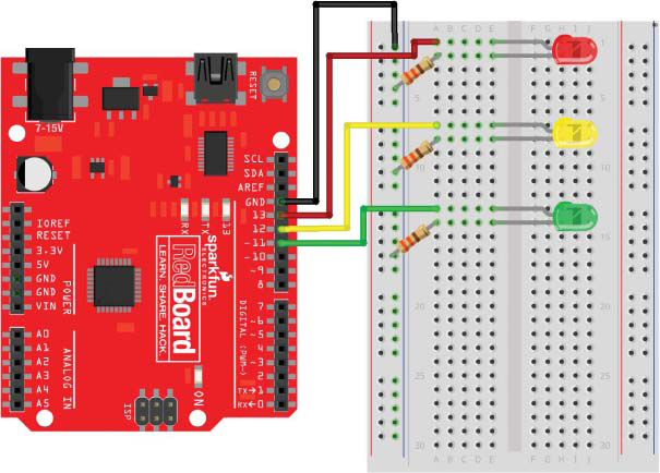
Each LED should have its own resistor wired to the ground rail, just like the schematic from Figure 2-6. Notice, too, that we gave each LED a little space on the breadboard so that we could have room to plug in wires without messing up other parts of the circuit. Although we suggested a specific way to plug in this circuit, remember that you can use any part of the breadboard—so long as the two wires you’re trying to connect are in the same row. Once you’re done, your circuit should resemble Figure 2-11.
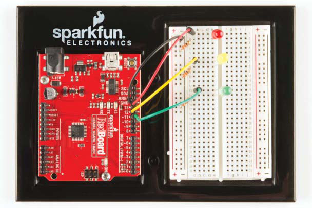
FIGURE 2-11: The completed Stoplight circuit, including the Arduino, LEDs, and resistors
To mimic a real stoplight, this project needs a way to turn on each light for a certain amount of time and then switch to the next one. Fortunately, an Arduino sketch can use all kinds of instructions, including timing commands, to control a circuit.
PROGRAM THE STOPLIGHT
Now, plug your Arduino back into your computer. It’s time to get programming! Open the Arduino IDE to start a new sketch.
Confirm Your IDE Settings
When writing any sketch, you should always start with a little housekeeping. First, check that the Board type and Port are properly set. Click Tools ▸ Board now. If you’re using the SparkFun RedBoard or a standard Arduino Uno, select Arduino/Genuino Uno. Then, click Tools ▸ Port. In Windows, your Arduino should be set to the highest numbered COM port. On OS X or Linux, the port should be listed as /dev/cu.usbserial-A<xxxx>, where <xxxx> is a string of random characters unique to your Arduino.
Create Placeholders for Pin Numbers
With your IDE settings confirmed, you’re ready to create the sketch. As discussed in “Anatomy of an Arduino Sketch” on page 27, a basic Arduino sketch consists of two parts: the setup() function and the loop() function. That simplified description is true for most simple sketches, but more complex sketches have many different parts. One new part that the Stoplight sketch uses is the global namespace, which is the part of your sketch above the setup()function and completely outside of any function. In this space, you can define certain names (variables) as placeholders for values, and these values will then be available for all parts of your sketch to use. Arduino sketches can work with several types of values.
Data That Sketches Understand
The Arduino language includes a number of possible data types for values, and there are a few you’ll run into often when writing sketches. The following list isn’t exhaustive, but it touches on the big ones and shows how their names appear in code:
Integer (int) A whole number that ranges from –32,768 to 32,767
Float (float) A number that has a decimal point and ranges from –3.4028235E+38 to 3.4028235E+38
Byte (byte) A number that ranges from 0 to 255
Character (char) A single letter, denoted by a set of single quotes, such as ‘a’
String (String) A series of characters, denoted by a set of double quotes, such as "hello"
Boolean (Boolean) A value of either true or false, which maps to 1 or 0 in the sketch and HIGH or LOW in terms of pin output
Arduino sketches require you to specify the data type of a variable when you define it. Let’s look at how that works.
Values That Can Change
Most values you’ll create to use in your sketches will be variables. Think of a variable as a placeholder for a piece of data. That data can be a number, a letter, or even a whole sentence.
Before you can use a variable, you have to define it, which includes giving it a name, declaring its data type, and initializing it with a value. It’s a good habit to give a variable a value at the moment you define it, which looks something like this:
➊int ➋val = ➌10;
This variable definition has three parts: the data type ➊, the name of the variable ➋, and the variable’s value ➌. At the end of this line, notice that there is a semicolon—this denotes the end of a statement or instruction. The semicolon is very important, and forgetting it is often the root cause of many compiler errors or bugs in code, so be careful to remember it!
When choosing a variable name, you can use any unbroken set of characters, including letters and numbers. There is one caveat here: variables cannot start with a number or consist of any special characters. We suggest making variable names as descriptive as possible, while keeping them short. It’s a chance for you to be a little creative with abbreviating words and descriptions. In this example, we chose to name the variable val (short for value), and 10 is the variable’s initialized value, or the value assigned to a variable to start with. You don’t need to initialize a variable when you define it, but doing both at the same time is helpful and a good practice.
For this project, you’ll create three variables to store pin numbers for the three LEDs the Arduino will control. It’s a lot easier to work with a variable that describes an LED color than it is to try to remember which LED is connected to which pin!
Start a new sketch, and add the code in Listing 2-1 to the global namespace of your sketch.
LISTING 2-1: Variables that represent pin numbers
byte redPin = 13;
byte ylwPin = 12;
byte grnPin = 11;
Again, these three variables store the pin numbers for the three LEDs. On the Arduino, pin numbers are limited to whole numbers between 0 and 13, so we use the byte data type. We can use byte because we know that the pin number will be less than 255. Notice that each variable’s name describes what it contains: redPin is for the red LED pin, ylwPin is the yellow LED pin, and grnPin is the green LED pin. And, just as Figure 2-10 shows, the red pin is pin 13, yellow is pin 12, and green is pin 11. Now, anytime you use a pin number in your sketch, you can use the descriptive variable name instead.
NOTE
For legibility, we camel-cased the variable names by capitalizing the p in pin. Camel-casing is a coding convention that allows you to separate words in a variable without using spaces.
Write the setup() Function
To continue writing the Stoplight sketch, add the setup() function in Listing 2-2.
LISTING 2-2: setup() code for the Stoplight
void setup()
{
//red LED
pinMode(redPin➊, OUTPUT➋);
//yellow LED
pinMode(ylwPin, OUTPUT);
//green LED
pinMode(grnPin, OUTPUT);
}
Just like the “Hello, world!” sketch in Project 1 (see “The setup() Function” on page 30), this sketch configures the digital pins of the Arduino in setup() with the pinMode() function.
This project uses three different digital pins, so the sketch has three separate pinMode() functions. Each function call includes a pin number as its variable ➊ (redPin, ylwPin, and grnPin) and the constant OUTPUT ➋. It uses OUTPUT because this sketch controls LEDs, which are output devices. We’ll introduce INPUT devices in Project 4.
Write the loop() Function
Next comes the loop() function. Normal stoplights cycle from red to green to yellow and then back to red, so this project does, too. Copy the code from Listing 2-3 into the loop() portion of your sketch.
LISTING 2-3: loop() code for the Stoplight
void loop()
{
//red on
digitalWrite(redPin, HIGH);
digitalWrite(ylwPin, LOW);
digitalWrite(grnPin, LOW);
delay(2000);
//green on
digitalWrite(redPin, LOW);
digitalWrite(ylwPin, LOW);
digitalWrite(grnPin, HIGH);
delay(1500);
//yellow on
digitalWrite(redPin, LOW);
digitalWrite(ylwPin, HIGH);
digitalWrite(grnPin, LOW);
delay(500);
}
The Stoplight will have only one light on at a time, to avoid confusing your hallway traffic and causing chaos. To maintain order, each time an LED is turned on, the other LEDs should be turned off. For example, if you wanted the red light to be on, you’d call the function digitalWrite(redPin, HIGH), followed by digitalWrite(ylwPin, LOW) and digitalWrite(grnPin, LOW). The first call writes HIGH to turn on the red LED on redPin (pin 13), and the other two calls write LOW to ylwPin and grnPin (pins 12 and 11) to turn off the yellow and green LEDs. Because the Arduino runs at 16 MHz (roughly one instruction per 16 millionth of a second), the time between these commands is on the order of a few microseconds. These three commands run so fast that you can assume they all happen at the same time. Finally, notice the function delay(2000). This function pauses the sketch and keeps the red light on for 2,000 ms, or 2 seconds, before executing the next set of instructions.
The code for the yellow and green LEDs repeats the same concept, setting the corresponding pin to HIGH and the others to LOW and delaying for different lengths of time. For your own Stoplight, try changing the delay times to something a little more realistic for your hallway’s traffic. Remember that the value you pass to the delay() function is the amount of time you want the LED to stay on in milliseconds.
Upload the Sketch
After you’ve typed in all of the code, double-check that it looks like the code in Listing 2-4, save your sketch, and upload it to your Arduino by clicking Sketch ▸ Upload or pressing CTRL-U. If the IDE gives you any errors, double-check your code to make sure that it matches the example code exactly. Your instructions should have the same spelling, capitalization, and punctuation, and don’t forget the semicolon at the end of each instruction.
When everything works, your LEDs should turn on and off in a cycle that is similar to a real stoplight—starting with a red light, followed by a green light, and then a short yellow light before returning to the top of the loop() function and going back to red. Your sketch should continue to run this way indefinitely while the Arduino is powered.
LISTING 2-4: Complete code for the Stoplight
byte redPin = 13;
byte ylwPin = 12;
byte grnPin = 11;
void setup()
{
pinMode(redPin, OUTPUT);
pinMode(ylwPin, OUTPUT);
pinMode(grnPin, OUTPUT);
}
void loop()
{
//red on
digitalWrite(redPin, HIGH);
digitalWrite(ylwPin, LOW);
digitalWrite(grnPin, LOW);
delay(2000);
//green on
digitalWrite(redPin, LOW);
digitalWrite(ylwPin, LOW);
digitalWrite(grnPin, HIGH);
delay(1500);
//yellow on
digitalWrite(redPin, LOW);
digitalWrite(ylwPin, HIGH);
digitalWrite(grnPin, LOW);
delay(500);
}
Make the Stoplight Portable
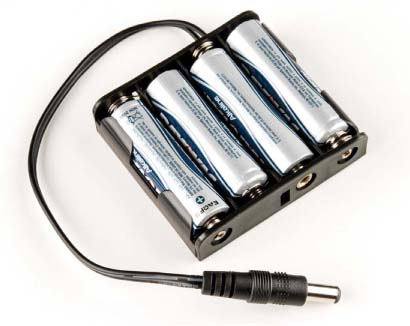
When your Arduino is connected to your computer, it’s receiving power through the USB port. But what if you want to move your project or show it around? You’ll need to add a portable power source—namely, a battery pack. The Arduino board has a barrel jack power port for plugging battery packs into, as well as an on-board voltage regulator that will accept any voltages from about 6 V to 18 V. There are many different battery adapters available, but we like using a 4 AA battery adapter for a lot of our projects, as shown in Figure 2-12.
FIGURE 2-12: A 4 AA battery pack with a barrel jack adapter
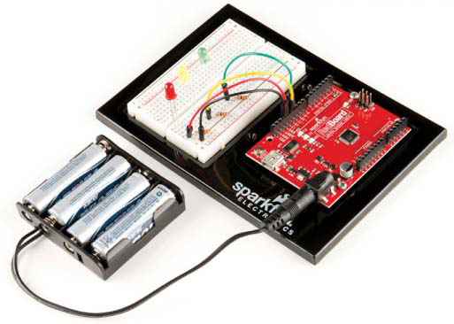
Unplug the USB cable from your computer, insert four AA batteries into your battery pack, and plug your portable battery pack into your Arduino, as shown in Figure 2-13. If your batteries are charged, you can move your project around or embed it directly into a model stoplight!
FIGURE 2-13: Making the Stoplight portable by adding a battery pack
Now you’ll level up this project. In the next section, we’ll show you how to turn these LEDs into a model stoplight that you can mount in high-traffic areas of your house.
BUILD THE STOPLIGHT ENCLOSURE
Once your Arduino isn’t tethered to a computer, you can build any electronics project into a more permanent enclosure. The circuit on your breadboard is great, but you probably have to use your imagination to picture it as a stoplight. For maximum effect, the Stoplight just needs a good housing and lenses that will make the lights visible from a distance. The enclosure is optional if all you want to do is prototype, but we hope you’ll try it out.
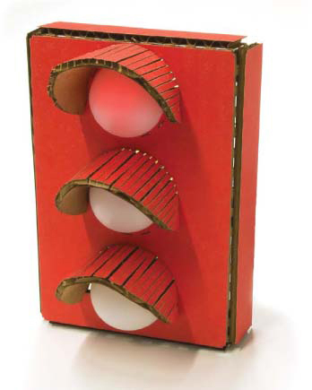
For this project, we’ll show you how to build a more realistic-looking stoplight with some cardboard or cardstock, but you can use any material that you happen to have lying around. Be creative! Our example, shown in Figure 2-14, is made from some cardboard, ping-pong balls, and a bit of crafting skill.
FIGURE 2-14: An enclosure made from cardboard and ping-pong balls
You can either build a stoplight on your own using this project only as an inspiration or, if you want to reproduce this project exactly as you see it here, download the ZIP file of templates and sketches at https://www.nostarch.com/arduinoinventor/. Each project in this book includes templates that you can print, trace, and hand-cut the old-fashioned way with a craft knife and a metal ruler.
NOTE
If you’re lucky enough to have access to a cutting machine like a Cricut, a Silhouette Cameo, or a laser cutter, these files should easily translate to those tools, too.
Extract the Project 2 files from the ZIP file, and print the Stoplight template PDF at full size if you’d like a cutting guide. With your templates in hand, collect the other items listed in “Other Materials and Tools” on page 39 and start building.
Cardboard Construction
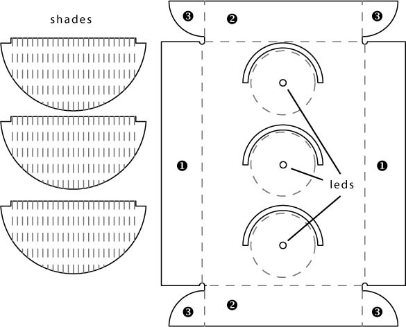
First, cut out the templates, shown in Figure 2-15. In our template, the housing body is a single piece of cardboard that is meant to be cut out, scored, and folded.
Trace the template onto your cardboard, and make careful note of the dashed lines, perhaps by drawing them on your cardboard in a different color. You’ll score the cardboard along those lines to bend it, so whatever you do, don’t cut along them yet.
FIGURE 2-15: Enclosure template for the Stoplight (not full size)
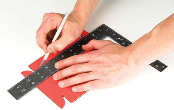
Once you have everything traced, cut out the stoplight pieces along the solid lines using a craft knife and a metal ruler, as shown in Figure 2-16. If you’ve never used a craft knife before, be sure to read “Using Craft Knives Safely” on page 56. Score the cardboard for the housing along each dotted line, on the exterior side of the cardboard. When scoring cardboard, you take a couple of shallow passes with the craft knife (don’t cut all the way through). Don’t score the shades yet.
FIGURE 2-16: Scoring along the template with a craft knife and metal ruler
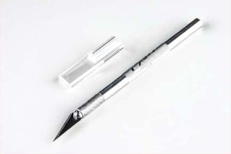
USING CRAFT KNIVES SAFELY
You’ll use craft knives a lot in this book, so it’s important to know how to safely use them. Just like any tool, when used incorrectly, craft knives like the one here can cause injury.
Here are a few tips for using craft knives safely:
• Always pull the blade when slicing through sheet materials. Pushing or forcing the blade in any other direction raises the potential for slipping or breaking the blade.
• Be patient. Don’t try to cut through the entire thickness of the material in a single pass. Make multiple passes with medium pressure. This will save your blade and also produce a cleaner finished product in the end.
• Use a straightedge made of metal, such as a metal ruler. If you use a wooden or plastic ruler as a straightedge, you run a higher chance of your blade catching the straightedge, rebounding off the material, and ultimately moving toward your hand.
• Keep your fingers out of the way. This may seem obvious, but accidents happen.
• If your knife starts to roll off your desk, let it fall, and just pick it up off the floor. If you reach for it and catch it before it falls, you run the risk of stabbing yourself in the hand. Ouch!
• Finally, use sharp, new, and intact blades. If a blade breaks, replace it. If a blade is dull, replace it. Cutting through paper and cardboard dulls blades very quickly. Keep a supply of extra blades around, and if it’s starting to get hard to cut, replace the blade.
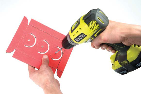
Once you have cut out your cardboard enclosure, add the mounting holes for the three LEDs; these should be at the little solid-lined circles inside the big dashed circles. One easy option is to carefully press a sharp pencil through the cardboard to make the holes. For cleaner holes, however, we suggest using a 3/16-inch drill bit and power drill to make holes in the cardboard, as in Figure 2-17. The LEDs are about 5 mm (about 0.197 inches) in diameter. You want the hole to be a nice, tight fit. So, a 3/16-inch hole (0.1875 inches) is perfect for making the fit snug for the LED.
Be careful when completing this step, and make sure to watch where your fingers and hands are relative to the drill bit. You don’t want to drill into yourself! You can also use the drill bit without the drill and manually spin it through the cardboard if you don’t have a drill or aren’t comfortable using one.
FIGURE 2-17: Drilling holes for the LEDs
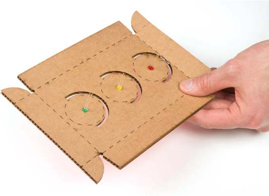
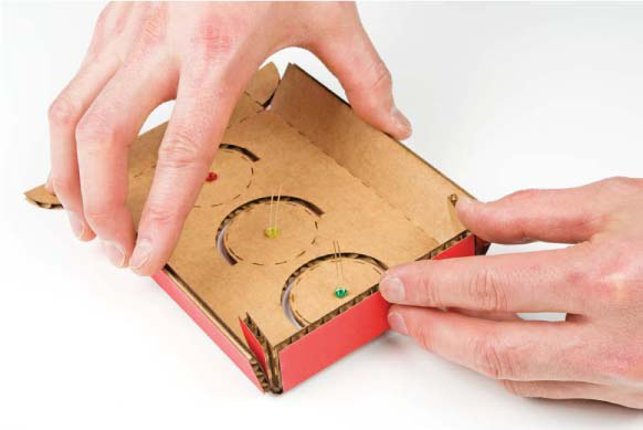
Once you have the holes drilled, remove the three LEDs from your breadboard and insert them through the back side of the cardboard, as shown in Figure 2-18. Remember that standard traffic lights are usually ordered red, yellow, and green from the top to the bottom. Pay attention to where the LEDs connect on the board, because we’re going to reconnect them at the end.
FIGURE 2-18: All three LEDs pressed into the cardboard
Next, bend the cardboard along the scored lines, as shown in Figure 2-19. Bend the vertical sides ➊ toward the interior, and then do the same with the top and bottom sides ➋ and the tabs ➌. (The sides and tabs are labeled in Figure 2-15.)
FIGURE 2-19: Prefolding the scored cardboard to form an enclosure for the Stoplight
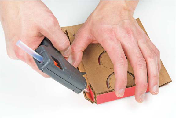
Position the tabs ➌ inside the vertical sides ➊, and glue them in place as shown in Figure 2-20. You can use hot glue, tape, or craft glue—we prefer hot glue because it’s easy to work with, sets quickly, and has a pretty strong bond.
Repeat this for the top and bottom corners. You should end up with a shallow rectangular box with an open back.
FIGURE 2-20: Folding and gluing the cardboard housing
Make the Stoplight Lenses
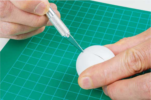
The Stoplight’s lenses are made from ping-pong balls cut in half, but you can use anything that’s moderately translucent.
If you’re using ping-pong balls or something similar, carefully cut two balls in half. When doing this, place the ball against a cutting mat or thick piece of cardboard and hold it firmly at the sides with your fingertips. Carefully push the knife blade down toward the mat and into the ping-pong ball (making sure the blade isn’t pointing at you or your hand) to make an incision as shown in Figure 2-21. Rotate the ping-pong ball and repeat until you’ve cut all the way through. Make sure to keep your fingers away from the blade, and always cut on a cutting mat or a piece of cardboard.
FIGURE 2-21: Safely cutting a ping-pong ball
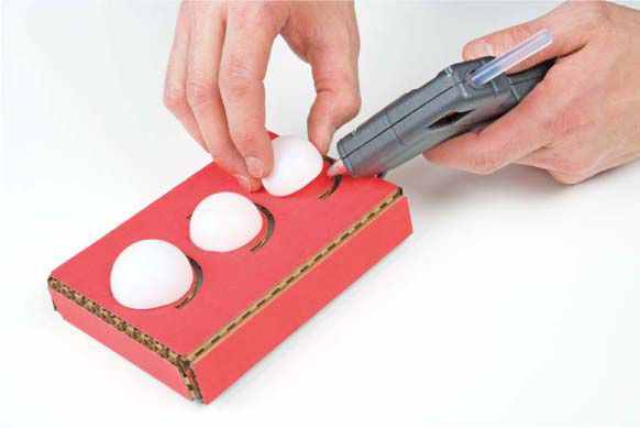
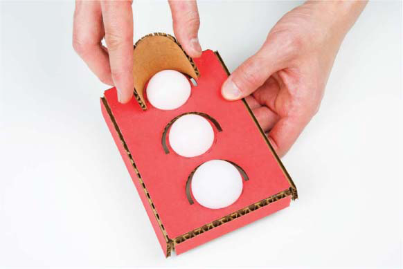
Once you have three ping-pong ball halves (you’ll have four; one’s an extra to use in future projects or as a small hat for your favorite stuffed animal), secure them with a dab of hot glue as shown in Figure 2-22.
FIGURE 2-22: The enclosure with ping-pong balls as lenses
Make the Shades
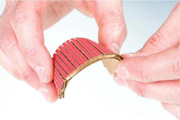
Finally, add the shades to the Stoplight. For a nice curve, make a number of parallel scores, about 1/8 inch apart, as shown in Figure 2-23. There are example score lines in the template, so you can follow those. After making all of your scores, bend each shade into a curve, as shown in Figure 2-24.
FIGURE 2-23: Scoring a shade
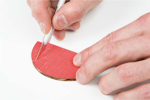
FIGURE 2-24: Bending the shade into a curve
Once you have the shades bent and shaped to your liking, fit them into the housing just above each lens, as shown in Figure 2-25, and then glue them in place. If you’re going for a more finished or realistic look, you can spray paint the housing black. Make sure you either remove the lenses or cover them with masking tape first so that they don’t get coated in spray paint.
FIGURE 2-25: Fitting a shade into the housing
Mount the LEDs and Arduino
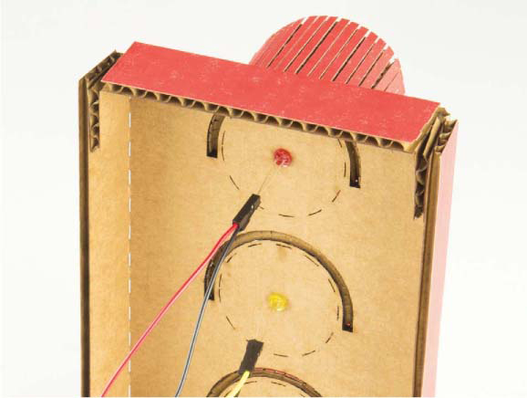
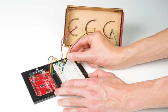
All you have left to do is to connect the LEDs from the new enclosure to your Arduino. First, use two male-to-female jumper wires (SparkFun PRT-09385) to extend each of the LEDs. You’ll need a total of six of these jumper wires. Simply plug each LED leg into the female end of the jumper wire. To keep things organized, we like to use black wires for the negative (shorter) leg and colored wires for the positive (longer) leg, as shown in Figure 2-26.
FIGURE 2-26: Attaching jumper wires to the LEDs
With the jumper wires connected to the LEDs, plug the male end into the breadboard in the same place where the LED came out, as shown in Figure 2-27. Again, pay attention to which LED goes where. If you don’t remember, consult the original diagram in Figure 2-10.
FIGURE 2-27: Inserting the male end of each jumper wire into the breadboard
Check to make sure your connections work by plugging in the Arduino to your computer or to a battery pack. If one of the lights isn’t working, try jiggling the connections or double-checking that the wires are plugged into the correct row on the breadboard.
You can either leave the Arduino and breadboard outside the Stoplight housing or tack them inside the housing with glue or double-sided tape. Whatever you decide, when you’re done, power up your Stoplight, and go find a busy hallway intersection in need of traffic safety.
Figure 2-28 shows the finished Stoplight in all its glory.
FIGURE 2-28: Finished Stoplight project
GOING FURTHER
The concepts you saw while building the Stoplight, such as timing the control of output (LEDs), can be applied to a number of different uses in your house and life. Here are a couple of suggestions for adapting the Stoplight.
Hack
The basic concept of a stoplight is all about timing. When else would a timer be useful? What about changing the code to help you time frying an egg? You could rework the Stoplight so that the red LED is lit while the egg is still in a state of “iffy” or “rare” doneness, the yellow LED lights when it’s almost cooked the way you like it, and then the green LED lights when the egg is done.
We can’t give you the timing, as we probably have different preferences for how we like our eggs cooked. There are also a number of variables that will affect the timing, like the temperature, the type of pan, and the size of the egg. You’ll have to figure that all out on your own.
In the code, you’d need to work with pretty big numbers for the delay, since it’s measured in milliseconds. To set a delay in minutes, all you need is a little multiplication. Remember that 1,000 ms equals 1 second; multiply by 60, and you’ll find that 60,000 ms equals 60 seconds, or 1 minute. For a delay of 3 minutes, you can multiply 3 by 60,000 directly in the delay() function, like this:
delay(60,000 * 3);
You may be wondering how long you can set the delay() function for. The data type that delay() receives is an unsigned long, which is any number that falls in the range of 0 to 4,294,967,295. So the maximum delay is 1,193 hours or so. Pretty cool! Knowing this, is there anything else you’d want to time with the delay() function?
Modify
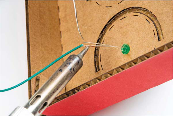
If you’re looking to make this project more permanent and sturdy, you can solder wires to the LEDs instead of using the male-to-female jumpers. If you’ve never soldered before, turn to “How to Solder” on page 302 for some soldering instructions before you start. You’ll need to snip the end off of a male-to-male jumper wire, strip the insulation back about 1/2 inch using wire strippers, and then solder the stripped end to each leg of a trimmed LED, as shown in Figure 2-29. Notice that we twisted the wire around the leg of the LED to hold it securely while soldering. After soldering, the connection will be more durable, and you’ll be able to use the LEDs for other projects since the other end is still a male jumper.
FIGURE 2-29: Soldering a cut jumper wire to an LED
Though this project looks impressive, the programming and hardware are pretty simple. As you read about sensors and logic over the next few chapters, we encourage you to think back to this project and brainstorm ways you can elaborate on it with what you learn.
All materials on the site are licensed Creative Commons Attribution-Sharealike 3.0 Unported CC BY-SA 3.0 & GNU Free Documentation License (GFDL)
If you are the copyright holder of any material contained on our site and intend to remove it, please contact our site administrator for approval.
© 2016-2026 All site design rights belong to S.Y.A.