The Arduino Inventor's Guide (2017)
Appendix
More Electronics Know-How
This appendix provides a how-to on using a multimeter and soldering, as well as a handy reference for reading the color bands on resistors.
MEASURING ELECTRICITY WITH A MULTIMETER
A multimeter is an indispensable tool used to diagnose and troubleshoot circuits. As its name states, it is a meter capable of measuring multiple things related to electricity—namely, current, continuity, resistance, and voltage. Let’s take a look at how to use a multimeter. We will be using the SparkFun VC830L (TOL-12966; shown in Figure A-1) throughout the tutorial, but these methods should apply to most multimeters.
Parts of a Multimeter
A multimeter has three main parts, labeled in Figure A-1.
FIGURE A-1: A typical multimeter
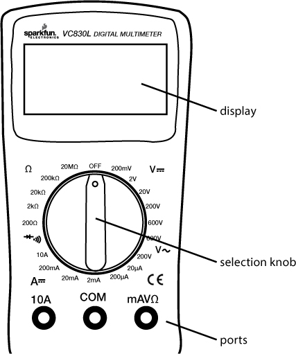
The display can usually show four digits and a negative sign. The selection knob allows the user to set the multimeter to read different things such as milliamps (mA) of current, voltage (V), and resistance (Ω). The numbers along the outside of the selection knob indicate the maximum value or range for any given setting.
On some multimeters, the display doesn’t show the units. In these cases, it is assumed that the values displayed have the same units as the setting, so if you have the range set to 200 Ω, the number displayed will be in Ω. If you have the range set to 2 kΩ, 20 kΩ, or 200 kΩ, then the value displayed will be in units of kΩ.
Most multimeters come with two probes, which are plugged into two of the three ports on the front of the unit. The three ports are labeled COM, mAVΩ, and 10A. COM stands for common and should almost always be connected to ground, negative, or the – of a circuit. The mAVΩ port allows the measurement of current (up to 200 mA), voltage (V), and resistance (Ω). The 10A port is the special connection used for measuring currents greater than 200 mA.
Most probes have a banana-type connector on the end that plugs into the multimeter, allowing for different types of probes to be used. For most measurements, connect the red probe into the mAVΩ port and the black probe into the COM port.
Measuring Continuity

Measuring continuity is possibly the single most important function for troubleshooting and debugging circuits. This feature allows us to test for conductivity and to trace where electrical connections have been made or not made. Set the multimeter to the continuity setting, marked with a diode symbol with propagation waves around it (like sound coming from a speaker), though this may vary among multimeters.
Touch the two probe ends together and you should hear a ringing tone—this is why checking for continuity is sometimes called “ringing out” a circuit. You can use this method to test which holes on a solderless breadboard are connected and which ones aren’t. The probe tips are usually too big to insert directly into a breadboard, but you can stick two wires in the same row on a breadboard and touch the ends of the probes to each wire. You should hear the tone indicating that these two wires are connected through the row. You can also use this method to trace out a circuit. Because you often can’t see where all of the wires go, this is a quick way to test whether two points are connected electrically. When you’re checking for continuity, it doesn’t matter which side of the probe you connect, because you’re just checking that one side is connected electrically to the other.
Measuring Resistance
![]()
The continuity setting simply rings a tone when the resistance is low, but to get an actual value for the resistance, you need to use a resistance setting. Turn the knob to one of the resistance settings marked by the omega symbol (Ω), which represents ohms, the unit for measuring resistance. Make sure that the resistor or the element you’re measuring is not powered or connected to your circuit. A resistor, like many electrical elements, has two ends. To measure its resistance, simply touch the ends of the probes to the ends of the resistor. As with continuity, it doesn’t matter which side you connect to red and which side you connect to black.
There are several possible resistance range settings available. These settings represent the maximum value you can measure. If you want to measure a small resistor to a high degree of accuracy, you would set the multimeter low—to 200 Ω, for example.
If you try to measure a resistance greater than the range, the multimeter will simply display [1. ], with no zeros displayed. If the resistance is greater than your chosen range, try moving the range up a notch and measuring it again.
Give it a try! If you measure the resistance of the 330 Ω resistor (orange-orange-brown), what values do you record for each setting? All resistors have a tolerance band; most are typically 5 percent. What is the percentage error for your measurement? Is it within the tolerance?
Test the resistance of the photoresistor. Hold your hand or something else opaque above the photoresistor, and measure the resistance for various heights.
Measuring Voltage
![]()
Voltage is a measurement of electrical potential between two points, sometimes also called the potential difference. Similar to the resistance settings, the various settings for measuring voltage specify the maximum value.
You’ll notice that there are two range symbols, one with two straight lines and one with a squiggly line. The two straight lines indicate direct current (DC) measurements, which are most commonly used in electronics. The squiggly line represents alternating current (AC), the type of electricity found in the walls of your house. Be sure that you have the knob turned to the right setting—you probably want DC. The 20 V setting is the best choice for the projects in this book, since all voltages are limited to 5 V on the Arduino.
Now, try to measure the voltage on an Arduino board. Plug your Arduino board into your computer using the USB cable for power. To measure voltage, connect the black probe to GND (ground). Now, use the red probe to test the voltage at various points or pins (with respect to GND). What does the 5 V pin show? How about the 3.3 V pin?
Measuring Current
![]()
Current is the rate of movement of charges in a circuit and is measured in amperes (amps). In order to capture the rate of moving charges and thus measure current, you need to break the circuit and connect the meter in-line at the place where you want to measure current. Adjust the knob to the appropriate current range that you expect to measure. If you’re measuring anything that might be above 200 mA, switch the selection knob to 10A and move the red probe into the port marked 10A on the body of the multimeter. If you’re not sure, this is the safest range to start with, to avoid damage to your meter.
To measure the current going through a simple LED and resistor circuit, for example, you could splice into the circuit between the LED and the resistor (see Figure A-2). The current path must go through the meter. Because this is a series circuit, you could measure the current anywhere along this path: before the LED, after the LED, or after the resistor.
FIGURE A-2: Splicing a multimeter into a circuit to measure current
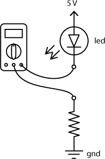
When measuring current, be very careful not to exceed the limits of your multimeter—you should be able to find the range of current your multimeter can handle from its user manual. If you go beyond the current limits, you run the risk of also blowing a fuse on the multimeter. (Don’t worry if you blow the fuse—a replacement is pretty inexpensive. In order to swap in the new fuse, you’ll probably need to open the back of the multimeter with a screwdriver.) The standard mAVΩ port can usually handle up to 200 mA.
HOW TO SOLDER
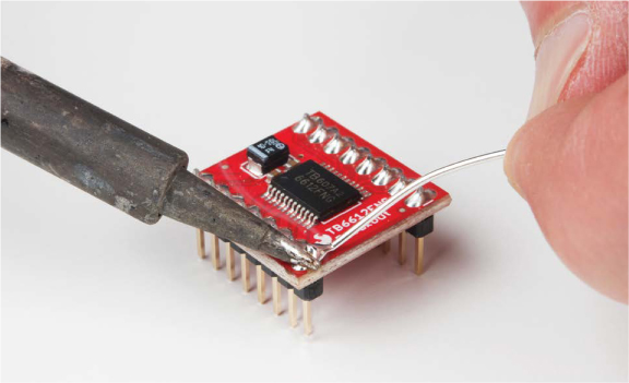
Soldering is one of the most basic skills used in prototyping electronics projects. It involves melting a special metal, solder, between two components to hold them together more permanently (see Figure A-3).
FIGURE A-3: Soldering
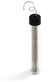
Solder, shown in Figure A-4, is a metal alloy with a relatively low melting temperature. Modern solder melts at a temperature of around 180 degrees Celsius or 356 degrees Fahrenheit, about the temperature you need to bake cookies. Most solder used for electronics has a core of flux, a cleaning fluid. As the solder melts, the flux helps to clean the surfaces being soldered and helps the solder flow.
FIGURE A-4: A roll of solder
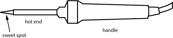
To perform soldering, you use a soldering iron. Most soldering irons are about the size of a medium carrot and have two main parts: the handle and the hot end (see Figure A-5).
FIGURE A-5: A typical soldering iron
There are many styles and types of soldering irons. Lower-cost irons can be about $10 and usually have a fixed temperature setting, but we suggest getting an iron with some type of temperature adjustment knob. The optimal temperature for an iron is about 650 degrees Fahrenheit. If it’s too hot, the tip will oxidize and get dirty quickly. If it’s not hot enough, it won’t melt the solder. An adjustable iron will help you control this, so it’s worth spending a little extra.
Be very careful when using a soldering iron: when you turn it on, the hot end will very quickly get hot enough to melt metal. That’s really hot! Always hold a soldering iron from the handle—you should never hold it from the hot end even when it’s off.
You should also protect the table surface you’re working on with a piece of cardboard, a cutting mat, or scrap piece of wood. And, before you start soldering, you should always wear eye protection. Little bits of solder and flux do sometimes sputter off. It’s best to keep your precious eyes safe!
Heating the Iron
To use a soldering iron, first plug in your iron and let it heat up. Depending on the type of iron you have, this may take anywhere between 30 seconds and a couple of minutes. While the iron is heating up, make sure it’s resting on a stand so that the hot end is not touching your table or work surface.
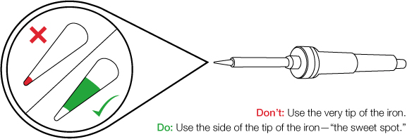
When the iron is hot, the solder should melt easily, so test this by touching a piece of solder with the side of the iron’s tip. This is the hottest part of the iron, known as the sweet spot (shown in Figure A-6), and it is the part you should use to apply heat to components. If the solder melts immediately, your iron is hot enough to solder.
FIGURE A-6: The side of the tip is much hotter than the very end of the tip.
Perfecting Your Soldering Technique
Contrary to what you might assume, when soldering you don’t actually touch the iron directly to the solder to melt it. The trick is to hold the iron to the components you’re intending to solder for around 2 to 3 seconds. Then you apply solder directly to the heated joint, and the solder will melt. Solder will always flow toward the heat and settle in the hottest part of the component. If you feed the solder directly onto the iron, it may glob up on the iron and not go onto the parts you want to solder. If this happens, simply clean the iron and try again. Hold the iron the same way you would hold a pencil, with your dominant hand, holding it from the handle. With your other hand, hold a length of solder. Be careful not to hold the solder too close to the end you’re melting, as the heat may travel up the length of solder to your fingertips.
Touch the sweet spot of the iron to the parts that you intend to solder. Be sure that the sweet spot of the iron is touching both parts that need to be soldered so that they heat up equally, as shown in Figure A-3. Count for three full seconds: one one-thousand, two one-thousand, three one-thousand.
Next, while holding the iron to the components, feed the end of the solder into the joint. Remember, the solder will flow toward the heat.
After you have fed enough solder so that the joint is filled, remove the solder, but hold the iron in place for one more second. This will allow the solder to flow and settle. Remove the iron from the joint, and place it back onto its stand.
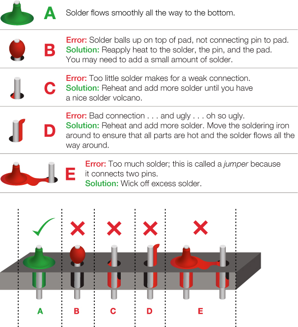
A good solder joint should be smooth and somewhat shiny. If you’re soldering onto a PCB, the joint often resembles a small volcano or chocolate candy kiss. Soldering takes practice, so if your solder joint doesn’t look clean and smooth, try reheating the joint to get the solder to flow and settle again, or add a bit more solder. Figure A-7 illustrates some common mistakes and possible solutions for soldering.
FIGURE A-7: Common soldering mistakes and solutions
Cleaning the Iron
Keeping the tip of the iron clean is one of the secrets to getting a good solder joint. We recommend cleaning it before each use by heating it up and using a brass scrubber or wet sponge to wipe off any excess solder and oxidation that may have built up.
If the tip is dirty and you can’t wipe off the excess buildup, you can use Tip Tinner and Cleaner (TOL-13246); this is a mixture of a mild acid and solder. To clean with this, heat the iron, place the tip of the hot iron into the tip tinner, and let the tip tinner eat away at the oxidation and buildup for about 10 to 15 seconds at a time. Then, wipe the tip off on the sponge. Repeat this process if necessary. The tip of the iron should be shiny.
Soldering Tips
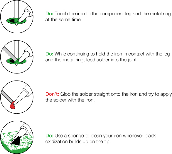
Figure A-8 shows a few additional hints and suggestions for using the soldering iron.
FIGURE A-8: Soldering hints and suggestions
NOTE
Some types of solder contain lead. We highly recommend washing your hands after doing any soldering regardless of the type of solder you use.
Using a soldering iron is a skill that should be in any maker’s arsenal. When you’re ready to make your prototype projects more permanent and durable, soldering will ensure that the wires and connections between components don’t get disconnected.
ADDITIONAL SOLDERING TOOLS
Here are a few additional tools we’d recommend you use to help you make the perfect solder joint each time. These tools help hold your parts, clean up your solder joints, and remove extra solder.
Third Hand
A third hand is basically a clamp to hold down the pieces you’re soldering and will be one of your best helpers for soldering. There are many versions of third hands, but most are simply a couple alligator clips on a heavy stand that will hold your parts while you’re using your hands to hold the solder and the iron. Many of the basic ones even come with a magnifying glass and a small soldering iron stand, too, as shown in Figure A-9.
FIGURE A-9: Third hand soldering stand

Flux Pen
One of the tricks to getting a good solder joint is to make sure everything is clean, which you can do with flux, a slightly acidic cleaning fluid often made from tree rosin. A flux pen (see Figure A-10) works a lot like a paint marker; you simply press the tip of the marker down on the solder joint you’re working on until a small puddle of liquid comes out onto your board. Apply the soldering iron directly to the joint and insert the solder and, using flux, the solder will melt a lot faster and bond better to your components.
FIGURE A-10: A water-soluble flux pen
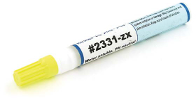
Flux does wonders for soldering, but it is somewhat corrosive, so make sure you minimize contact with your skin and wash your hands immediately after use.
Solder Wick
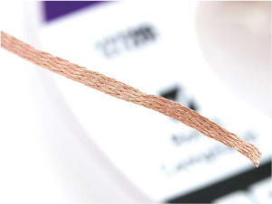
You’ll sometimes find when soldering that you’ve added too much solder or gotten solder in places that you didn’t intend. There are two tools to keep around on your bench that help remove unwanted solder. The first is solder wick, a finely braided copper mesh that resembles a ribbon, as shown in Figure A-11.
To use solder wick, place the wick over the solder joint you wish to remove, apply the heated soldering iron to the top of the wick to heat the wick and the solder joint below, and as the solder melts, it will wick away from your components into the copper mesh. Voilà!
FIGURE A-11: A close-up view of solder wick
Be sure to hold the iron on the wick as you remove both the wick and the iron from your board. If you pull the iron away too soon, the wick will be soldered onto your board. If this happens, simply reheat the joint to remove the wick.
Solder Vacuum
The second tool that can remove unwanted solder is called a solder vacuum or solder sucker. This nifty tool creates a vacuum using a plunger (similar to a syringe) and releases with the press of a button.
To use a solder sucker, first push down on the plunger to preload the tool. Next, heat up the solder joint you wish to remove until it is completely melted and liquid. Place the tip of the solder vacuum against the solder (while still holding the iron to keep it melted), and finally push the release button to suck away the unwanted solder.
If it doesn’t work, try again. It sometimes helps to add a bit more solder to the area you wish to remove solder from.
RESISTORS AND BANDS
Resistors come in a wide range of values, but how can you tell what the value is by looking at the tiny component? There are no numbers or text!
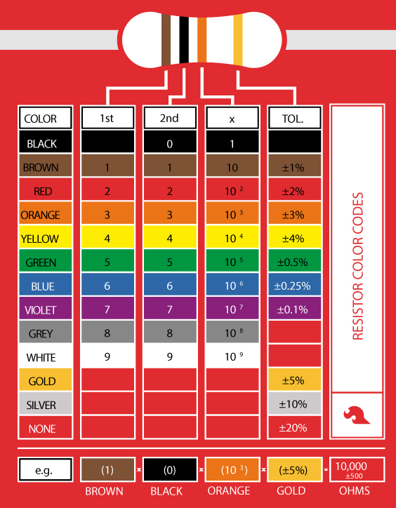
Resistors use a color band system to show their values. Figure A-12 shows how the banding system works.
Most resistors have four or five colored bands. The last band on the resistor specifies the tolerance, or the degree of variance, allowed by the manufacturer. Most of the time, your resistors will have a gold tolerance band, for 5 percent. This means the manufacturer allows 5 percent error on the value of that resistor. For example, the resistance of a 10 kΩ resistor with a 5 percent tolerance can fluctuate up to 500 Ω and still be considered a 10 kΩ resistor.
When you’re reading from left to right with the tolerance band (usually gold or silver) toward the right, the remaining bands specify the resistance value. On a four-band resistor, the first two bands specify the base number, and the third band is the multiplier. On a five-band resistor, the first three bands specify the base number, and the fourth band is the multiplier.
For example, the first three bands on a 10 kΩ resistor are brown, black, and orange. Following the chart in Figure A-12, brown equals 1, and black equals 0, so brown-black means the base number is 10. The third band is orange, which specifies a multiplier of 103, for a total of 10,000. Finally, the fourth band specifies the tolerance, which in this example is 5 percent (gold).
FIGURE A-12: Resistor color cheat sheet
In case you need to look up resistor color bands later, you may want to dog-ear this page for reference. It’s okay—we won’t tell the librarian.
Afterword
We hope you’ve enjoyed building the projects in this book. It was a lot of fun for us to come up with different project ideas that incorporated cardboard, paper, ping-pong balls, and other common materials, as well as the basic electronics. But the projects in this book are just a start. We hope they inspire you and help unleash your inner inventor! We encourage you to combine and mash up components and concepts from each of these chapters to create your own Franken-duino project! If you have comments or ideas that you’d like to share with us, please send us a note at ArduinoInventorsGuide@sparkfun.com.
Best of luck, and happy building!
All materials on the site are licensed Creative Commons Attribution-Sharealike 3.0 Unported CC BY-SA 3.0 & GNU Free Documentation License (GFDL)
If you are the copyright holder of any material contained on our site and intend to remove it, please contact our site administrator for approval.
© 2016-2026 All site design rights belong to S.Y.A.