The Arduino Inventor's Guide (2017)
10 Tiny Electric Piano
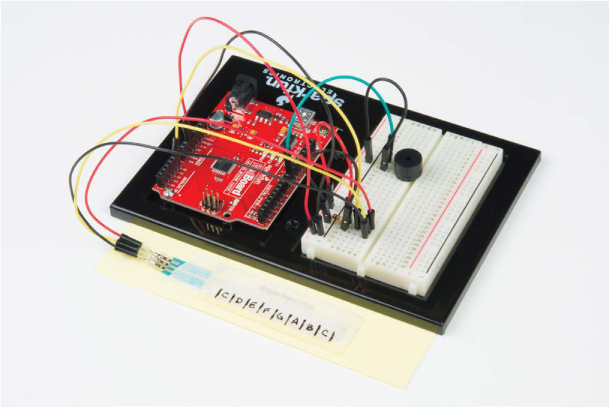
In this project, you’ll use a special touch sensor and a piezo buzzer to create an Arduino piano (Figure 10-1). Regardless of whether you have any musical talent, this will be a fun project!
FIGURE 10-1: A completed Tiny Electric Piano
MATERIALS TO GATHER
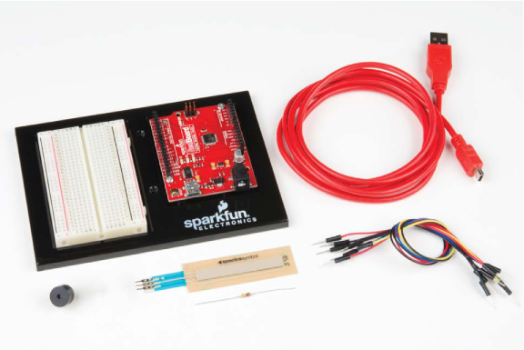
There are only a couple new parts in this project. One is the soft potentiometer (SoftPot), which will act as your keyboard, and the other is the piezo buzzer, which will provide the sound. The supplies you’ll need are shown in Figures 10-2 and 10-3. Grab your materials, and let’s get started.
Electronic Parts
• One SparkFun RedBoard (DEV-13975), Arduino Uno (DEV-11021), or any other Arduino-compatible board
• One USB Mini-B cable (CAB-11301 or your board’s USB cable)
• One solderless breadboard (PRT-12002)
• One 10 kΩ resistor (COM-08374, or COM-11508 for a pack of 20)
• One 50 mm SoftPot membrane potentiometer (SEN-08680)
• One piezo buzzer (COM-07950)
• Male-to-male jumper wires (PRT-11026)
NOTE
All of the parts used in this project are standard in the SparkFun Inventor’s Kit.
FIGURE 10-2: Components for the Tiny Electric Piano
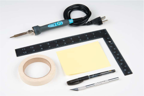
Other Materials and Tools
• Pencil
• Craft knife
• Metal ruler
• (Optional) Soldering iron
• Masking tape
• Cardboard or cardstock (about 4 × 5 inches) or a small cardboard box
FIGURE 10-3: Additional supplies
NEW COMPONENTS
As we mentioned, this project will introduce just two new parts. The first is a SoftPot touch sensor: a special kind of potentiometer that is similar to the one used in Project 6 but reacts to pressure. The second new part is a piezo buzzer. Let’s take a look at these two parts in more detail.
The SoftPot Membrane Potentiometer
In Project 6, we introduced a simple potentiometer with a knob that you could turn to control the Balance Beam. The SoftPot, shown in Figure 10-4, works similarly but reacts to pressure instead of knob rotation.
FIGURE 10-4: A 50 mm SoftPot
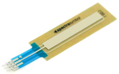
The SoftPot is a thin and flexible sensor that can detect where along its length pressure is applied. When you press down, the resistance between the middle pin and the closest end pin varies between 0 Ω and 10 kΩ, depending on how much pressure is detected. The SoftPot sensor has a thin membrane that separates the center pin connection from the outer ones. This sensor is very accurate and has a nearly infinite resolution. In industrial applications, the SoftPot is often used to identify the position of sliding parts, robot arms, and other components that make precision movements.
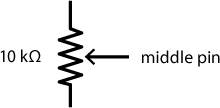
In this project, you’re going to use this sensor as your piano keyboard. You’ll divide the length of the strip into eight sections or “keys” that you can use to play various notes. The SoftPot is effectively the same as a knob potentiometer used in earlier projects. In schematics and circuit diagrams, you may recognize the symbol as pictured in Figure 10-5.
FIGURE 10-5: The schematic diagram for the SoftPot is identical to that of the regular potentiometer.
The Piezo Buzzer
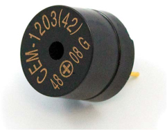
The piezo buzzer (Figure 10-6) is similar to a speaker and produces an audible click when you apply a voltage to the two leads; these clicks happen very fast, several hundreds or even thousands of times per second, and their frequency creates a tone. Inside a typical piezo buzzer is a special crystal called a piezo element that deforms when voltage is applied. The crystal is connected to a round metal disc, and when the crystal deforms, the disc vibrates the air inside a small cylinder, producing the clicking sound.
FIGURE 10-6: Piezo buzzer
NOTE
The buzzer that’s included in the SparkFun Inventor’s Kit actually uses a small magnetic coil instead of a piezo element, but it works the same. We still refer to it as a piezo buzzer.
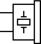
You’ve already seen how you can blink an LED at various rates with the Arduino. Now, if you “blink” the buzzer at a rate of hundreds of times per second, we can convert these clicks into tones! There are several different electrical symbols used to represent buzzers, speakers, and similar elements. The symbol we’ll use in this chapter is shown in Figure 10-7.
FIGURE 10-7: Electrical symbol for a piezo buzzer
BUILD THE CIRCUIT
This circuit uses only two electronic elements: the buzzer and the SoftPot, shown in Figures 10-8 and 10-9. When inserting the buzzer into the breadboard, you may notice that the legs are slightly closer together than the holes of the board. Just gently bend the legs apart so that the pins line up with the holes and insert the buzzer. The legs should be three holes apart.
The SoftPot has three legs like the potentiometer you used in Project 6. But unlike a regular potentiometer, the SoftPot requires a pull-down resistor to ensure that, when there is no input or pressure on the sensor, the SoftPot defaults to a nominal state of 0. This will prevent the buzzer from making noise when you aren’t pressing on the sensor.
FIGURE 10-8: Schematic diagram of the Tiny Electric Piano circuit
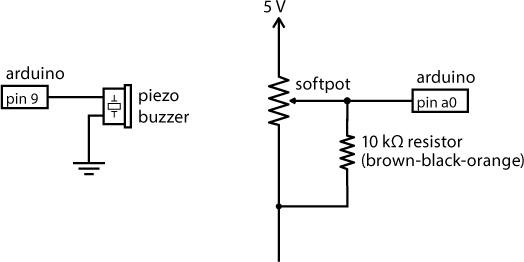
FIGURE 10-9: Prototype of the Tiny Electric Piano circuit on the breadboard
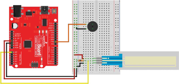
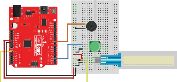
Assemble the circuit as shown in the diagram. The circuit is fairly simple. First, connect 5 V and GND to the power and ground rails on the left side of the breadboard. Next, add the buzzer roughly 10 rows down from the top of the breadboard. Connect one leg of the buzzer to pin 9 of the Arduino and the other leg of the buzzer to the ground rail. Then, insert the SoftPot near the bottom of the breadboard. Connect the top pin of the SoftPot to the 5 V power rail, the lower pin to the ground rail, and the middle pin to the analog input pin A0 on the Arduino. Remember that the SoftPot requires a pull-down resistor between the wiper pin (middle pin) and the ground rail. Finally, add a 10 kΩ resistor between the middle pin and the ground rail.
Once you have it built, it’s time to try a couple of code examples.
PROGRAM THE TINY ELECTRIC PIANO
First, you’ll test the build by having the buzzer make noises and recognizable tones, and then you’ll map those noises and tones to the SoftPot. Once you know how to get your code making sounds, we’ll show you how to add functionality so that you can play up to eight distinct notes, like a small piano.
You’ve already seen that the Arduino can generate really fast pulses and react to split-second button presses. With your circuit wired up, you’ll use these capabilities to make some fun sounds and test the frequency response of the buzzer.
Test the Buzzer
Arduino has a few commands that make playing notes really simple. There are two functions that control making sounds with Arduino: tone(), which tells the buzzer to play a frequency you specify, and noTone(), which tells the buzzer to stop the sound so you can control the length of the note. Here’s how you use these two functions.
//creates a tone of frequency on pin for a duration in ms
tone(pin, frequency, duration);
//stops the playing of a tone on the given pin
noTone(pin);
The tone() function needs to be called with three parameters: the pin number the buzzer is connected to, a frequency you want to play, and the duration to play the note. When called, tone() creates a square wave at the frequency you provided on the defined pin for a specific duration. This square wave triggers the vibration of the disc inside the buzzer connected to this pin, creating a sound at that frequency. Once started, tone() continues for the duration specified or until you call either another tone() command with a different frequency or the noTone() command to stop the Arduino from playing.
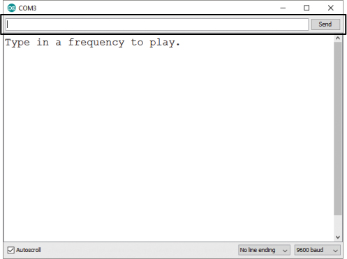
Copy the code from Listing 10-1 into the Arduino IDE or download the sketch from https://www.nostarch.com/arduinoinventor/. In this example, you’ll use the Serial Monitor to choose a frequency, and the buzzer will play that tone for half a second.
LISTING 10-1: Serial tone test code
//Serial Tone Test Example
//Upload this example and then open the Serial Monitor
int freq;
void setup()
{
➊ pinMode(9, OUTPUT);
Serial.begin(9600);
Serial.println("Type in a frequency to play.");
}
void loop()
{
➋ if(Serial.available() > 0) //wait for a serial
//input string
{
➌ freq = Serial.parseInt(); //parse out integer value
Serial.print("Playing note: "); //user feedback
Serial.println(freq);
➍ tone(9, freq, 500); //play the note for 500 ms
➎ delay(500); //delay for the note duration
}
else
{
noTone(9);
}
}
Let’s take a look at how this all works. In the setup(), the sketch sets the pinMode ➊ for the GPIO pin on the buzzer, initializes the serial communication on the Arduino, and prints a short message instructing the player on what to do.
Next, inside the loop(), the if(Serial.available() > 0) statement ➋ checks for data sent over serial communication like so: Serial.available() returns the number of bytes received from the Serial Monitor, and the if() statement compares that value to zero; if the number of bytes is greater than zero, it means data was received, and the script reads the data ➌. The Serial.parseInt() function converts the data into an integer, which is then stored in the variable freq.
The code plays the frequency stored in freq for 500 ms using the tone() function ➍ and then has a short delay() ➎. The delay() ensures that the note plays for the full 500 ms before starting another note. The tone() command is a nonblocking function: it executes and then continues to the next instruction without waiting.
After uploading this sketch to your device, open the Serial Monitor (CTRL-SHIFT-M or Tools ▸ Serial Monitor). Then, click the line-ending-character drop-down list (Figure 10-10), and select No line ending. When you send data between digital devices, an invisible end-of-line (EOL) character is sometimes used to indicate the end of a message. The two most commonly used EOL characters are the new line (NL) and carriage return (CR). While the character may appear to be invisible, to the Arduino this character still reads in as a value. Selecting this option makes sure that it doesn’t send any extra characters.
Now, in the box at the very top, you can type any number and press ENTER, and the buzzer will play that note for half a second (500 ms). The range of human hearing is about 20 Hz to 20,000 Hz, so play around with some different frequencies, but keep them within that range.
FIGURE 10-10: Open the Serial Monitor, and change this option to No line ending.
The serial communication on the Arduino has a buffer 64 bytes long. A buffer is like a waiting line for the data as it goes into the device, and in this case it allows you to send several notes at a time using the Serial Monitor. For example, you can play the song “Twinkle, Twinkle, Little Star” by typing in the following numbers, separated by commas without spaces. The last comma is important, too. The Serial.parseInt() command looks for numeric characters that are separated by non-numeric characters like commas. The Arduino needs to see that last token (the final comma) to parse out the final note.
262,262,392,392,440,440,392,392,349,349,330,330,294,294,262,262,
Make sure to omit the spaces here. Each character is equal to 1 byte of data, and if you try to send more than the maximum 64 bytes at a time, the last few pieces of data will get cut off.
Lastly, the buzzer is optimized at 2,047 Hz. You may notice that when you try this frequency the buzzer is very, very loud and can be annoying, so be warned: people around you may not appreciate the high-pitched tones that come out of this buzzer at 2,047 Hz!
Create Specific Notes
If you want to try something more traditional, you can correlate actual musical notes to frequencies. Many instruments use a reference point of middle C, which has a frequency of about 262 Hz. Table 10-1 shows a short table of frequencies for an octave of the C major scale.
TABLE 10-1: Notes and frequencies of the C major scale
|
NOTE |
APPROXIMATE FREQUENCY |
|
C |
262 |
|
D |
294 |
|
E |
330 |
|
F |
349 |
|
G |
392 |
|
A |
440 |
|
B |
494 |
|
C |
524 |
Experiment and see if you can play a song. To start you off, “Twinkle, Twinkle, Little Star” begins with the notes CC, GG, AA, GG, FF, EE, DD, CC. You may notice that the sounds the Arduino makes aren’t the most melodic. This is because the Arduino can only turn the pin either HIGH (on) or LOW (off). This creates a square wave, which has a tinny pitch. There are some tricks you can do using capacitors to create a noise filter to soften this sound, but that’s a topic for another book!
Generate Sound with the SoftPot
Making music with frequencies is fun, but typing them over and over gets really tedious. Instead, you can use the SoftPot as a sensor whose values will correspond to frequencies for the buzzer.
The SoftPot is wired up with a simple voltage divider so that a pressure on the length of the strip will be translated into a voltage from 0 to 5 V. Remember that the Arduino can translate an analog voltage from 0 to 5 V to a value of 0to 1023 using the analogRead() function. Using the simple sketch in Listing 10-2, you can send frequencies to the buzzer by pressing the SoftPot. When the SoftPot is not pressed, the value defaults to 0 because of the pull-down resistor, so no sound is produced.
Start a new Arduino sketch, copy the code example from Listing 10-2, and upload it to your device.
LISTING 10-2: Noisemaker example code
//Noisemaker Example
//upload this example, open the Serial Monitor,
//and then squeeze the SoftPot
➊ int sensorValue;
void setup()
{
pinMode(9, OUTPUT);
Serial.begin(9600);
}
void loop()
{
➋ sensorValue = analogRead(A0);
➌ if (sensorValue > 0) //if there's a press on sensor,
//play note
{
➍ Serial.print("Raw sensor reading: ");
Serial.println(sensorValue);
➎ tone(9, sensorValue, ➏50);
delay(➐50);
}
➑ else
{
noTone(9);
}
}
Let’s take a look at what’s going on in this sketch. You again start by declaring a variable to store the raw sensor reading ➊. In the loop, the analogRead() function reads the voltage on pin A0 ➋ and assigns this value to the variable sensorValue. This value will be 0 V when no pressure is applied. You use an if() statement ➌ to check if the input value is greater than 0, and if it is, the sketch prints the raw sensor value ➍ and uses the tone() command ➎ to play the value stored in sensorValue. If the sketch is getting stuck playing a note, try changing the 0 in the if() statement to a larger number like 10 or 20 ➌. This is a technique called setting a deadband range. Some sensors don’t always go back to a zero value, so this deadband sets a range of values that the program can still consider to be zero. Each sensor may be slightly different.
Notice that in this example we changed the duration the tone() is played ➏ and the delay() ➐ to 50 ms. This will allow you to create faster changes in notes. Otherwise, you would only be able to play notes that were half a second long! Finally, you want to make sure that the Arduino only plays a tone when the SoftPot is pressed. To do this, you use the else() statement to detect when the SoftPot is not being pressed ➑ and the noTone() command to turn the buzzer off.
Now, instead of using a frequency sent from the Serial Monitor, the Arduino uses the raw sensor value from the SoftPot. To play around, simply squeeze the SoftPot between your thumb and index finger, applying pressure at different points along the sensor. As you slide your fingers up and down the SoftPot, you can generate tones from 1 Hz to 1,023 Hz. What do you hear? Does it sound like aliens are landing? Pretty cool—now you have your very own special effects generator! Can you play anything that resembles a song? If not, take a look at the next example.
Play a Song
Now that you have a feel for how the Arduino can make sounds, it’s time to map the sensor readings of the SoftPot to real notes so you can make actual music. You’ll break the sensor up into eight distinct sections (or keys) and map these to an index that you can use to play notes.
Copy the sketch in Listing 10-3 into the Arduino IDE, and upload it to your device.
LISTING 10-3: Tiny Electric Piano sketch
//Tiny Electric Piano Example Code
➊ int frequencies[] = {262, 294, 330, 349, 392, 440, 494, 524};
int sensorValue;
➋ byte note;
void setup()
{
pinMode(9, OUTPUT);
Serial.begin(9600);
}
void loop()
{
sensorValue = analogRead(A0);
if (sensorValue > 0) //if it's a note, play it!
{
//map the key pressed to a note
➌ note = map(sensorValue, 0, 1023, 0, 8);
➍ note = constrain(note, 0, 7);
Serial.print(sensorValue);
Serial.print("\t");
Serial.println(➎frequencies[note]);
tone(9, ➏frequencies[note], 50);
delay(50);
}
else
{
noTone(9);
}
}
Let’s look at the code. First, you declare a data structure referred to as an array. An array is a kind of variable that represents a list of values rather than just a single value. Arrays can be of any standard data type, including bytes, ints, longs, and floats, and you declare the data type before the array name.
Declaring an array is similar to declaring a variable except that the array name is followed by two square brackets, [ ]. When you initialize an array, you define the list inside two curly brackets, { }, and use commas to separate each value:
dataType arrayName[] = {val0, val1, val2, val3, val4... };
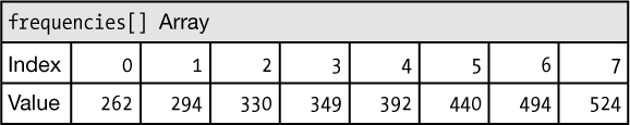
Listing 10-3 declares an integer (int) array named frequencies[] that stores a list of eight values for the frequencies of the musical notes ➊. You can access the values in the array using the index number of the value, placed between square brackets. The first value is referenced as frequencies[0], the second is referenced as frequencies[1], and so on. Notice, as usual, that the index starts at 0 rather than 1, as shown in Figure 10-11.
FIGURE 10-11: The frequencies[] array elements
The sketch then declares an index variable named note ➋. The array has only eight values, so you can declare this variable as a byte since it uses less memory space than an integer. Next, the sketch uses the map() function ➌ to translate the raw sensorValue reading in the range 0–1,023 to a 0–8 scale.
The map() function is a great tool for converting from one range of values to another. You pass it the input value, the range of the input, and the desired range, and it will scale your input value to the desired range, like so:
map(inValue, inMin, inMax, outMin, outMax);
The sketch assigns this scaled value to the variable note. This will be the index to reference the array. But while the map() function scales the 0–1,023 range to a range of 0–8, the frequencies[] array actually has only eight values and is indexed from 0 to 7.
We do this because map() rounds down when it scales from one range to another range, so to get eight equally spaced values, we actually need to give it nine values. Value 8 is produced only when the input is equal to 1,023. Because value 8 (the ninth value) is not a valid index for the array, we correct this using another command, constrain() ➍. This function constrains the value to a range of 0 to 7. Any value that is below 0 is constrained to a minimum value of 0, and any value greater than 7 is constrained to a maximum value of 7. The constrain() function is often used in conjunction with map() to scale and limit a value.
The constrain() function is used like so:
constrain(value, minValue, maxValue);
Finally, the sketch prints the frequency of the current note being triggered to the Serial Monitor ➎ and uses the tone() function ➏ to play the note.
To test it out, press or squeeze the SoftPot. As you move your finger up and down the length of the sensor, you’ll hear the different notes. See what songs you can play.
Now, let’s turn this prototype into a finished piano!
BUILD THE PIANO
To convert the prototype into a more functional piano, you just need to apply it to a flat surface and mark out the eight keys.
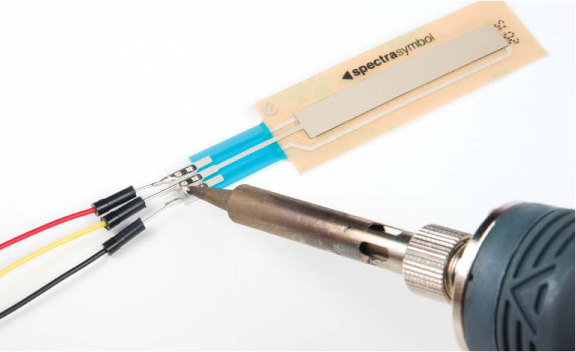
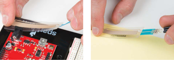
Unfortunately, the pins on this sensor are not long enough or thick enough to simply insert into the male-to-female jumper wires, so if you want to remove it from the breadboard, we suggest that you solder three male-to-male jumper wires from the Inventor’s Kit to the ends of the SoftPot, as shown in Figure 10-12. Alternatively, you can use male-to-female jumpers, but you’ll need to crimp the ends using a set of needle-nose pliers. If you do this, insert the sensor pins into a set of male-to-female jumper wires and crush the plastic casing around the sensor pins. Make sure that the wires are in contact with the pins of the sensor.
FIGURE 10-12: Soldering wires to the SoftPot
The SoftPot has adhesive backing designed to be placed flat on a hard surface, so with the wires attached, apply the sensor to any portable hard surface (Figure 10-13), like a small piece of cardboard or even the breadboard holder itself.
FIGURE 10-13: Options for mounting the SoftPot
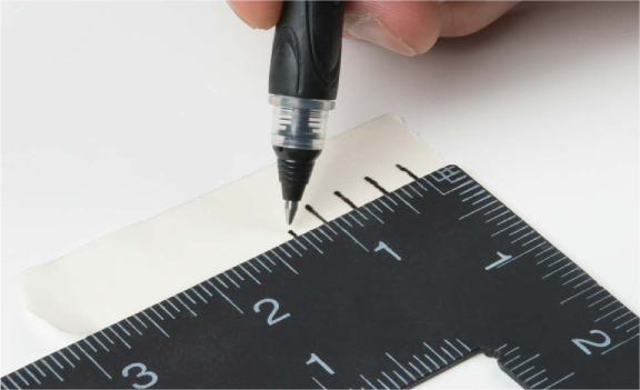
The SoftPot sensor is 50 mm long (approximately 2 inches). You need to divide the length of the sensor into eight keys, which means each key should be roughly a quarter inch wide. Using a piece of masking tape or a sheet of paper, mark off eight quarter-inch keys, as shown in Figure 10-14.
FIGURE 10-14: Marking off the keys
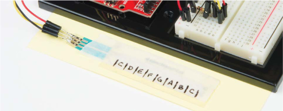
Next, position the masking tape or paper on top of the SoftPot to give you a guide for playing the notes. The completed keyboard should look like Figure 10-15. If you like, you can label the keys with the notes matching the frequencies in your code to help you play from sheet music.
FIGURE 10-15: The finished Tiny Electric Piano keyboard
GOING FURTHER
In this project, we introduced you to the piezo buzzer and SoftPot. Now that you know how to make some fun sounds, here are a few ideas for taking this project further.
Hack
Play around with the code and see what other fun tones you can create. If you want to play a song in a different key or using a different scale, for example, you could change the frequencies in the array. Table 10-2 shows frequencies you can use to change the key of your piano. C major and G major are the two most common scales used in music. Find some sheet music online or just mess around. Can you play “Twinkle, Twinkle, Little Star” on your new SoftPot piano?
TABLE 10-2: Selected approximate frequencies for notes across three octaves
|
NOTE |
APPROX. FREQ. |
NOTE |
APPROX. FREQ. |
NOTE |
APPROX. FREQ. |
|
C3 |
131 |
C4 |
262 |
C5 |
524 |
|
C♯3/D♭3 |
139 |
C♯4/D♭4 |
277 |
C♯5/D♭5 |
554 |
|
D3 |
147 |
D4 |
294 |
D5 |
587 |
|
D♯3/E♭3 |
156 |
D♯4/E♭4 |
311 |
D♯5/E♭5 |
622 |
|
E3 |
165 |
E4 |
330 |
E5 |
659 |
|
F3 |
175 |
F4 |
349 |
F5 |
698 |
|
F♯3/G♭3 |
185 |
F♯4/G♭4 |
370 |
F♯5/G♭5 |
740 |
|
G3 |
196 |
G4 |
392 |
G5 |
784 |
|
G♯3/A♭3 |
208 |
G♯4/A♭4 |
415 |
G♯5/A♭5 |
831 |
|
A3 |
220 |
A4 |
440 |
A5 |
880 |
|
A♯3/B♭3 |
233 |
A♯4/B♭4 |
466 |
A♯5/B♭5 |
932 |
|
B3 |
247 |
B4 |
494 |
B5 |
988 |
Modify
To make things more interesting, add a distortion pedal to this piano project. This button will switch up octaves to give you 16 notes for the price of 8. Connect a button to pin 2 on your Arduino as shown in Figure 10-16.
The sketch needs just few extra lines of code for the pedal, which will cycle a multiplier variable each time the button is pressed. This is known as a state machine, because each time the button is pressed, the state of a variable is changed. The code for this modification is in the book’s resources at https://www.nostarch.com/arduinoinventor/ in the file P10_TinyPiano_v2.ino.
FIGURE 10-16: Adding a button to pin 2 for octave control
The new code lines declare a state variable, octaveMultiplier, and then add a pinMode() command to set up pin 2 as an INPUT. When the button is pressed, the state variable, octaveMultiplier, is incremented, altering the frequency so that the note goes up.
Try it out. When you press the button, the notes should all go up by an octave. You now can play up to 16 notes with this simple Arduino instrument!
Bonus Project: Binary Trumpet
The SoftPot is a nice touch, but as a bonus we’ve built an Arduino instrument that uses actual buttons as keys instead of the SoftPot. This last project is called the Binary Trumpet. It uses three buttons to specify which note to play and the fourth button to play the note, like blowing on a trumpet. With three buttons, you can specify up to eight different combinations using the keypresses shown in Table 10-3.
TABLE 10-3: Binary trumpet button sequences
|
BUTTON 1 |
BUTTON 2 |
BUTTON 3 |
NOTE TO PLAY |
|
Up |
Up |
Up |
C (262 Hz) |
|
Up |
Up |
Down |
D (294 Hz) |
|
Up |
Down |
Up |
E (330 Hz) |
|
Up |
Down |
Down |
F (349 Hz) |
|
Down |
Up |
Up |
G (392 Hz) |
|
Down |
Up |
Down |
A (440 Hz) |
|
Down |
Down |
Up |
B (494 Hz) |
|
Down |
Down |
Down |
C (524 Hz) |
You may recognize this pattern as a binary sequence. It counts in the order 000, 001, 010, 011, 100, 101, 110, and 111.
To make room for the four buttons on the breadboard, move the buzzer up a little and then add those buttons, as shown in Figure 10-17.
FIGURE 10-17: Binary Trumpet wiring diagram
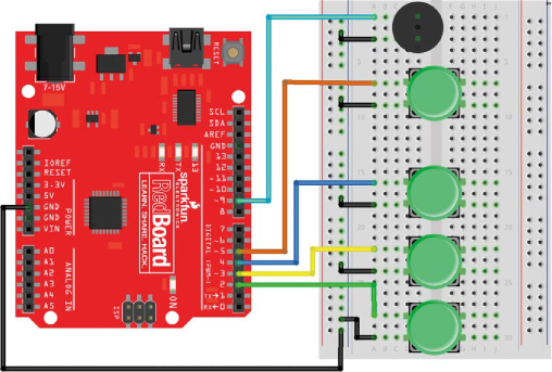
The complete code for this modification is in the book’s resources at https://www.nostarch.com/arduinoinventor/ in the file P10_TinyBinaryTrumpet.ino. Playing notes using the Binary Trumpet will take a bit of getting used to, but the sequence of presses in Table 10-3 should help you as you pick it up.
As it turns out, with four buttons, you can actually play up to 16 different notes. Can you figure out how to modify the example to do this? Take a look at the book’s resources to see how.
Whether you use the Tiny Electric Piano or the Binary Trumpet, we hope this helps you on your way to a future career in making music. Now go forth and find an audience to show off your newest skills!
All materials on the site are licensed Creative Commons Attribution-Sharealike 3.0 Unported CC BY-SA 3.0 & GNU Free Documentation License (GFDL)
If you are the copyright holder of any material contained on our site and intend to remove it, please contact our site administrator for approval.
© 2016-2026 All site design rights belong to S.Y.A.