Make: AVR Programming (2014)
Part III. Advanced AVR Topics
Chapter 15. Advanced Motors
H-Bridges and Stepper Motors
In Chapter 14 we discussed how to use the AVR to drive big loads in the simplest, on-off case. Adding in PWM to the mix allows you to, for instance, vary the speed of a motor. That’s great, right? Now your little robot is going forward fast and forward slow. But what do you do when you want to put it in reverse?
In this chapter, I’ll introduce you to some useful concepts for more advanced motor-driving. The first step in all this is to build (or buy) a circuit that can reverse a DC motor by applying voltage to it in either polarity. Such a circuit is called an H-bridge, and I’ll go into detail about how you can build your own if you need to.
If you are only driving small motors, there is very probably a premade solution out there that is cheaper, easier, and more reliable than building your own. For instance, the SN754410 chip provides two full H-bridges in one package.
Finally, we’ll dip our toes into driving stepper motors. Steppers are great for fairly accurate positioning coupled with decent speed. Driving one stepper motor is roughly equivalent to driving two DC motors, but we’ll see that some coordination (in code) is necessary.
For fun and inspiration, a bunch of motors that I’ve driven with the AVR code and SN754410 H-bridge chip are shown in Figure 15-1. These include stepper motors on the left, gear motors in the middle, and two small plain DC motors on the bottom right.
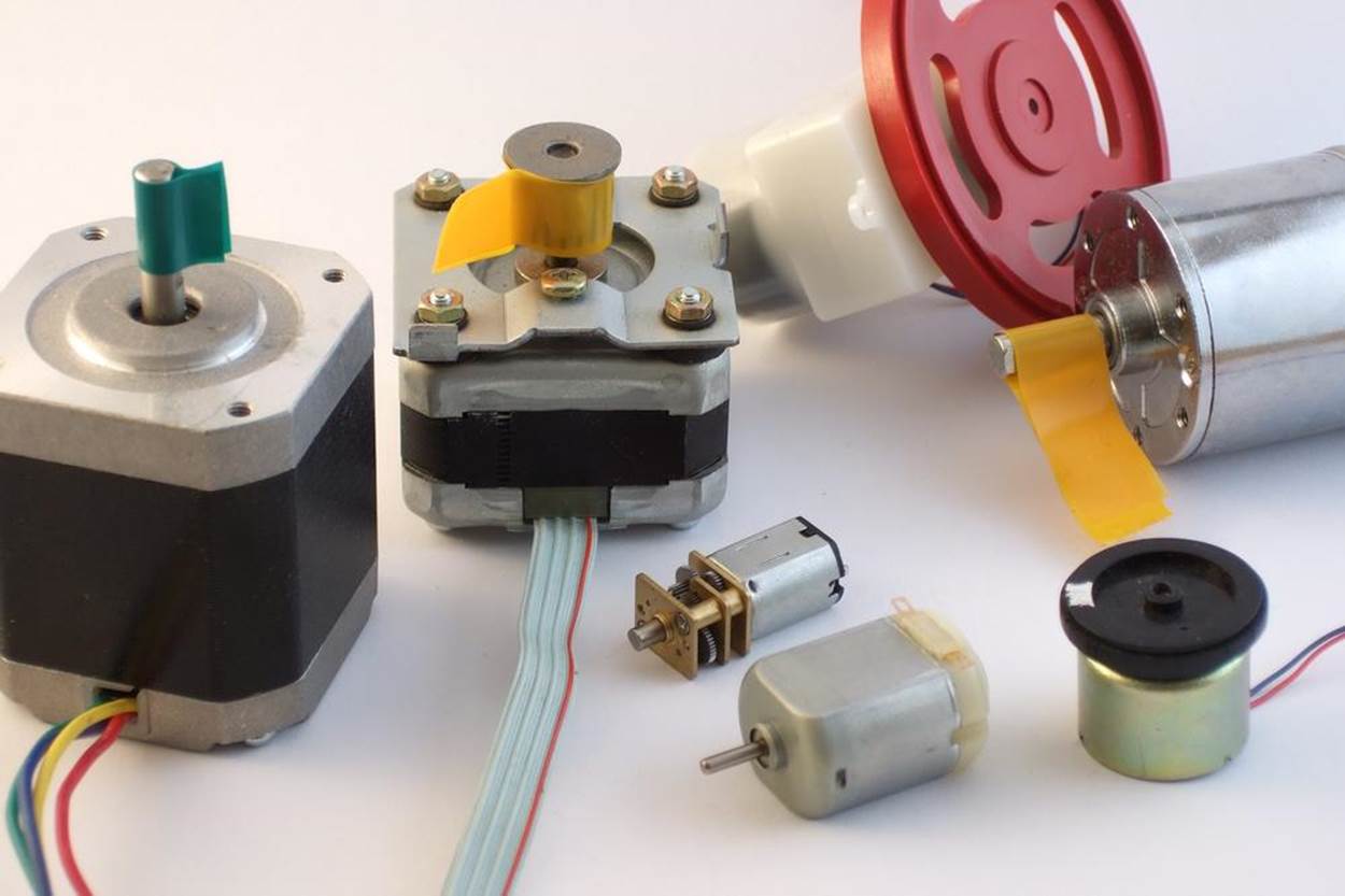
Figure 15-1. Motors, motors, motors
This chapter doesn’t have finished projects so much as demonstrations of the key ideas and circuits necessary for handling these advanced motor modes. What you build them into is entirely up to you!
WHAT YOU NEED
For this chapter, what you’ll need depends on how much you’d like to get out of it.
For experimenting with H-bridges:
§ A DC motor and a power supply capable of driving it. Many small model-car motors will run on 4–6 V, or 4xAA batteries.
§ MOSFETs for building an H-bridge. I use two IRF9530s, two IRF530s, and two of our standby 2N7000.
§ If you don’t want to build an H-bridge by yourself but just want experience with using one, you’ll need one of either an SN754410 or L293D chip.
§ A USB-Serial adapter.
For experimenting with stepper motors:
§ A stepper motor and a power supply to drive it. Because we’re just experimenting, any old stepper that you can find will work. A junked printer or scanner will probably have a 9–12 V stepper motor inside it if you’d like to take one apart. A 9 V battery is just right in that case.
§ A working H-bridge. If you didn’t build your own in the first section, an SN754410 or L293D chip is a very good choice.
§ A USB-Serial adapter.
Going in Reverse: H-Bridges
If you want to run your DC motor backward, and you’re hooking things up by hand, all you have to do is reverse the polarity on the motor by swapping the wires around. How are we going to do the same thing electronically? The answer turns out to be a circuit called an H-bridge. Unfortunately, there’s no such thing as a DIY H-bridge circuit that’s simple, powerful, and efficient. We’ll go through a couple of designs here, starting with simple and inefficient and ending with powerful and efficient but a bit complicated. Of course, you can also go out and buy a wide range of motor-driver and H-bridge chips ready-made that’ll do as good a job, or better, than anything you can make yourself.
To reverse a DC motor, you need to be able to drive one side of the motor either high or low, while the other side is driven low or high, respectively. An H-bridge achieves this with two switches, a high-side and a low-side switch, for each motor connection. Have a look at the rough sketch in Figure 15-2 and you’ll see why they call it an “H” bridge.
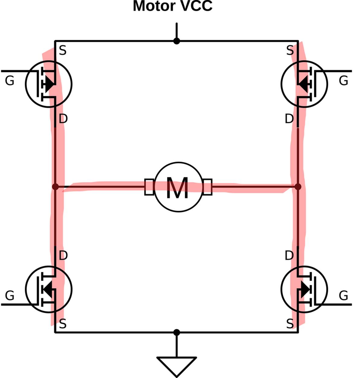
Figure 15-2. H-bridge sketch
Each side of the H-bridge is just a push-pull MOSFET driver, in exactly the same configuration as the circuitry inside the digital I/O pins on the AVR but using higher-wattage components. To understand how it works, first look at one side of the H. When the top P-channel FET is turned on and the lower N-channel FET is off, the side is pulled to the motor-high supply voltage. Turn off the top switch, and turn on the low-side switch, and the voltage is pulled down to ground. This way, you can set either side of the H to high or low voltage. Now if you drive one side to the high voltage while the other is low, current flows and the motor spins. Switching the roles of the two sides reverses the motor. Success!
There are a couple of complications to this circuit, though. The first is how to interface this circuit with the AVR. The low-side FET is easy enough, and it will sink as much as 5 A with a 5 V AVR output with the parts specified. The high-side FET is trouble, though. To turn it on, you just have to pull the line low, which is easy enough. To turn it fully off, though, you need to raise the gate voltage to the same as the source of the FET, which is at the motor supply voltage. If you’re running motors that want 9 V or 12 V or even more, you can’t close the high-side switch without some intermediate circuitry.
The other danger with this circuit sketch is shoot-through. What would happen if you opened both the upper and lower switches on the same side? If each MOSFET has an on resistance of about half an ohm, the total resistance is only 1 ohm, or just about as much as you’d get if you put a screwdriver across the battery terminals: not good! The battery will put out as much current as it can, and something will burn: either the battery, your wiring, or the MOSFETs.
Finally, note that I picked a pair of MOSFETs with similar part numbers. These are designed to be used as a complementary pair and have similar characteristics. This matters a lot for controlling shoot-through and can be a gotcha when you’re designing your own circuits. Because the high-side and low-side FETs we use are matched and have similar switch-on times, we can get away with a single signal to open one and close the other. (With random MOSFETs, you’ll want some circuitry to control shoot-through.)
So with matched MOSFETs on the high and low side, we can drive them both at the same time. Because they’re complementary, one will turn off just about as the other turns on. Now you might be tempted to drive these as is with the AVR’s output pins, and that’s not a horrible idea for low-voltage applications where the motor voltage is up to 5 V.
Things get more complicated when you want to drive a motor with more voltage than the AVR’s VCC. The low-side switch is no problem—many FETs (and our IRF530s) will push a fair amount of current when the gate is held at 5 V with respect to ground. The problem is that you can’t shut off the high-side switch completely without a source of 9–12 V, and the AVR’s output pins aren’t going to cut it any more. So what we’re going to do is use transistor switches to drive our transistor switches as shown in Figure 15-3.
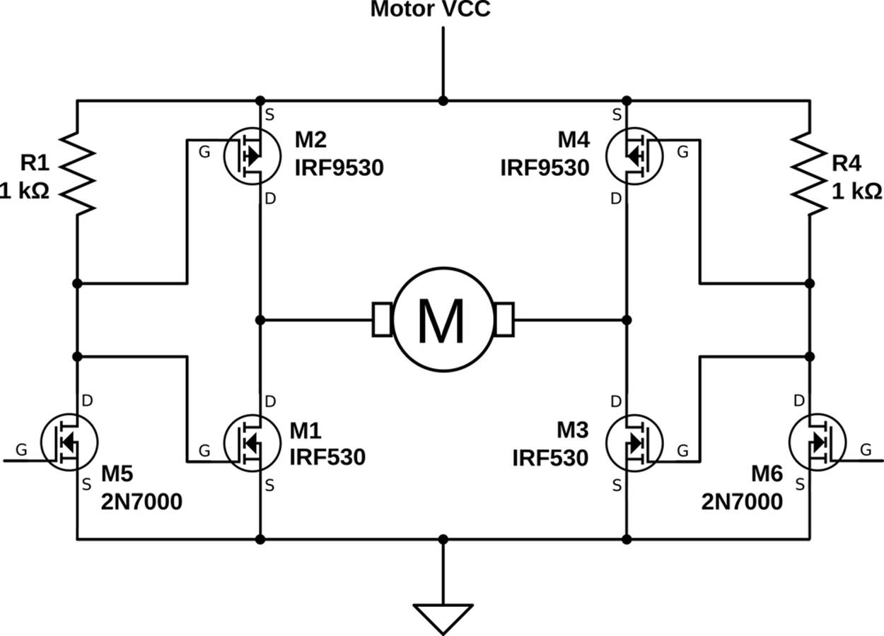
Figure 15-3. Working H-bridge
This H-bridge is stable and “smokeproof” (meaning, it’s not possible to send it into a short-circuit mode through software). If the bridge is not hooked up to the AVR or if the AVR is sending a logic low, the gate of the 2N7000 is low and the 2N7000 is not conducting. If the 2N7000 is not conducting, the voltage on the power MOSFETs is pulled up by the 1k ohm resistor to the motor power supply level, which shuts off the high-side MOSFET and fully opens the low side, which essentially grounds this side of the bridge.
When the left side 2N7000 gets a logic high voltage, it conducts and pulls both power MOSFETs’ gates to ground. The low-side power MOSFET turns off when grounded, and the high-side MOSFET turns fully on, so the whole side is pulled strongly high. So a high signal to the half-bridge driver sets the output high, and vice versa.
Code: Taking Your H-Bridge Out for a Spin
The drive modes for this bridge are really simple. Because the state of the half-bridges mimics their input, you can just pretend that the AVR digital output is driving the motor, and the bridge will take care of the heavy lifting. This means that if you want the motor to rotate one way, simply set one AVR output pin high and the other low. To reverse, switch the high and low values. Easy!
But what happens when both sides of the bridge are held high or both held low? The motor doesn’t know anything about high or low voltages. It only sees the voltage difference across its terminals. So if the motor wasn’t moving to begin with, the modes (high, high) and (low, low) don’t do anything. Both of these modes are just like connecting a wire across the two terminals of the motor. On the other hand, if the motor was already turning and then you switch to (high, high) the situation gets more interesting—you’ve just shorted out the terminals of a moving motor.
Look back at Figure 15-3, and think back to the motor-as-generator discussion in Motor as Generator. For concreteness, let’s imagine that the motor was being powered (high, low) just before getting turned off to (high, high). Because the motor windings are inductors, they want to keep the current flowing in the same direction as their magnetic fields wind down. So the current will want to flow in a loop from the motor, up the open high-side FET, over to the other high-side FET, and back down into the motor. But because the motor is a generator, as long as it’s turning, it’s making a voltage that opposes this current. When you short-circuit a running motor, these two opposing voltages act like an electronic brake for the motor and stop it faster than it would if you just disconnected it.
So before we get to controlling both speed and direction by applying PWM to the circuit, let’s play around with digital logic control of the bridge to get a good feel for how it works in Example 15-1. In the following H-bridge examples, the PD5 and PD6 pins (that we’ve used for the speaker and antenna previously) are connected to the bridge. If these are still hooked up, it might be time to pull them out or even to start up a new breadboard with another AVR chip.
Example 15-1. hBridgeWorkout.c listing
// Simple demo of an h-bridge
// ------- Preamble -------- //
#include <avr/io.h>
#include <util/delay.h>
#include <avr/interrupt.h>
#include "pinDefines.h"
static inline void setBridgeState(uint8_t bridgeA, uint8_t bridgeB) {
/* Utility function that lights LEDs when it energizes a bridge side */
if (bridgeA) {
PORTD |= (1 << PD6);
LED_PORT |= (1 << LED0);
}
else {
PORTD &= ~(1 << PD6);
LED_PORT &= ~(1 << LED0);
}
if (bridgeB) {
PORTD |= (1 << PD5);
LED_PORT |= (1 << LED1);
}
else {
PORTD &= ~(1 << PD5);
LED_PORT &= ~(1 << LED1);
}
}
int main(void) {
// -------- Inits --------- //
DDRD |= (1 << PD6); /* now hooked up to bridge, input1 */
DDRD |= (1 << PD5); /* now hooked up to bridge, input2 */
LED_DDR |= (1 << LED0);
LED_DDR |= (1 << LED1);
// ------ Event loop ------ //
while (1) {
setBridgeState(1, 0); /* "forward" */
_delay_ms(2000);
setBridgeState(0, 0); /* both low stops motor */
_delay_ms(2000);
setBridgeState(0, 1); /* "reverse" */
_delay_ms(2000);
setBridgeState(1, 1); /* both high also stops motor */
_delay_ms(2000);
// For extra-quick braking, energize the motor backwards
setBridgeState(1, 0);
_delay_ms(2000);
setBridgeState(0, 1);
_delay_ms(75); /* tune this time to match your system */
setBridgeState(0, 0);
_delay_ms(2000);
} /* End event loop */
return (0);
}
The code includes one convenience function that takes a pair of values, one for each side of the H-bridge, and sets that output pin and an indicator LED. So if you call setBridgeState(1,0) it will turn on both the first H-bridge side and the first LED, and turn off the second H-bridge side and second LED. Then the rest of the code enables output by setting the DDR for each and starts demoing the four possible H-bridge drive states.
At the very end, I try an experiment with reversing the motor while it’s still running in an attempt to get it to brake faster. Especially if your motor has a heavy wheel on it, you may be able to notice that using reverse as a brake stops the motor even faster than the two “normal” braking modes. Anyway, it’s a handy technique if you find your robot coasting down to a stop too slowly.
Experts-Only H-Bridge
If you’re using unmatched P-channel and N-channel FETs, or you’re looking for more control, you can also drive the high side and low side separately as shown in Figure 15-4. This comes with the benefit that you can fine-tune the opening and closing times of the upper and lower FETs so that they’re as fast as possible without shoot-through even with unmatched parts by tweaking the relative timing of signals in software.
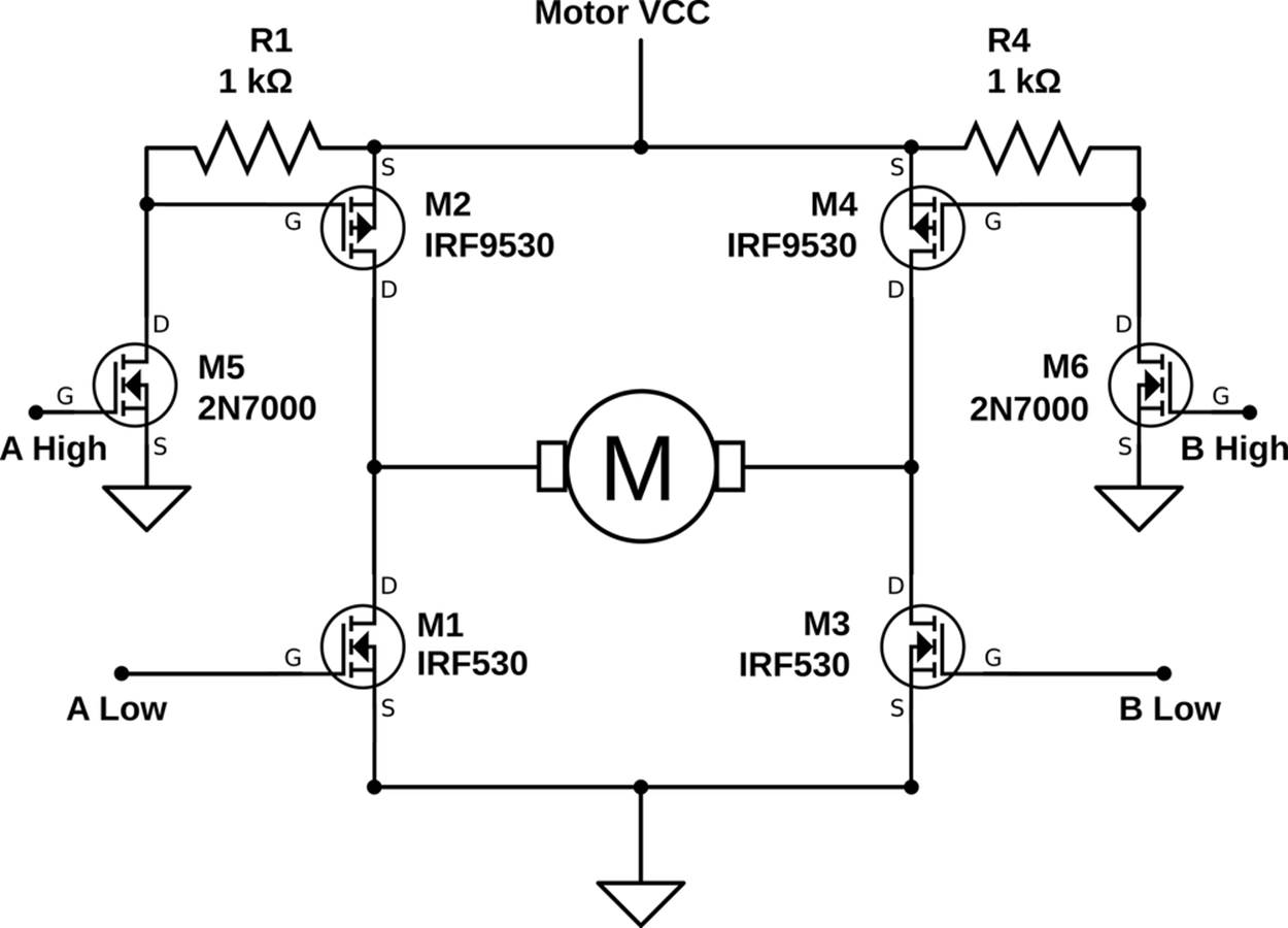
Figure 15-4. Four-wire H-bridge
If you hook up an H-bridge as in Figure 15-4, think super hard about the polarity of the control signals. In particular, when the “A High” signal is written high, the 2N7000 conducts, pulling the MOSFET gate low, which makes it conduct. When the “A Low” signal is written logic high, it also conducts. So what you’re never going to want to do is have the AVR drive the two pins on the same side high at once.
On the other hand, driving both pins on the same side low at once opens both the upper and lower MOSFET switches, which leaves the motor to spin mostly freely. This mode is often called “coasting.” If all four switches are open, it’s like the motor isn’t connected to anything at all and is free to turn.
There are also four other modes where only one transistor conducts, which end up being like coasting except that one leg of the current passes through a flywheel diode and one through a transistor. These modes are interesting for high-speed PWM, because you can alternate between driving and not driving by simply toggling one switch.
But let me repeat my warning that you should be extra careful with this circuit. Never close both the top and bottom MOSFETs on either side at the same time. Nobody likes burnt MOSFETs.
PWM and the H-Bridge
Being able to move a motor forward and backward is great, but for a real-world robot, you’re going to want to have forward and backward with speed control. And the way to do this with digital outputs from your microcontroller is, of course, our old friend PWM. Because we’re dealing with more current and external switches, not to mention a motor with inductance, things get a tiny bit more complicated. Here, I’ll step you through what you need to know. We’ll be using both our home-made H-bridge and an SN754410 (or the similar, but lower current, L293D) H-bridge chip to demonstrate the two main PWM modes that are commonly used to control motor speed. Table 15-1 summarizes the four drive states available to us with a standard H-bridge circuit.
Table 15-1. Our H-bridge’s drive states
|
Left input |
Right input |
Current path |
Result |
|
0 |
0 |
Motor shorted, low side |
Braking |
|
0 |
1 |
Right to left |
“Forward” |
|
1 |
0 |
Left to right |
“Backward” |
|
1 |
1 |
Motor shorted, high side |
Braking |
With our H-bridge, we have three choices for driving the motor: forward, backward, and brake. This gives us basically two choices for PWM—alternating between forward and braking or between forward and backward. The first choice is called “sign-magnitude” drive, and the second is “locked-antiphase.” Each PWM drive mode has its advantages and disadvantages, both for our code and for the driving circuit, so let’s look at them briefly.
Drive Modes: Sign-Magnitude
Sign-magnitude drive is usually implemented in hardware motor drivers with two wires: one controls the direction of rotation (the “sign”) and the other is PWM-ed to control how fast it goes (the “magnitude”), as summarized in Table 15-2.
Table 15-2. Sign-magnitude drive
|
Sign |
Magnitude duty cycle |
Result |
|
1 |
100% |
“Forward” full speed ahead |
|
1 |
50% |
“Forward” half speed |
|
1 |
0% |
Dynamic braking |
|
0 |
0% |
Dynamic braking |
|
0 |
50% |
“Backward” half speed |
|
0 |
100% |
“Backward” full speed |
Sign-magnitude drive modes are usually implemented in a motor driver’s discrete IC logic circuitry, but we can do the same in code. When we’re going forward, we’ll leave one side permanently on high and assign the other side to PWM control so that it toggles between high and low to alternate between driving and dynamic braking with both high. Going backward just means switching which side stays permanently high (and reinterpreting the PWM).
Note that we’re using all three possibilities here—forward, reverse, and dynamic braking—although we’re not using all four possible bridge states. We never use the (low, low) braking state, but that’s OK because it’s the same as the (high, high) state for all intents and purposes.
Drive Modes: Locked Anti-phase
In locked anti-phase mode, you only use two of the H-bridge’s possible drives, forward and backward. The halves are “locked” to be out of phase with each other: when one is high, the other is always low. This simplification means that you could potentially control the bridge with just one wire, with both direction and speed controlled by the PWM duty cycle as summarized in Table 15-3.
Table 15-3. Locked anti-phase drive
|
PWM duty cycle |
Result |
|
100% |
“Forward” full speed ahead |
|
75% |
“Forward” half speed |
|
50% |
Stopped |
|
25% |
“Backward” half speed |
|
0% |
Backward"” full speed |
If you’d like to modify the H-bridge circuit for explicit locked anti-phase drive, you can add (yet another) 2N7000 and a pull-up resistor to invert the AVR’s signal as shown in Figure 15-5.
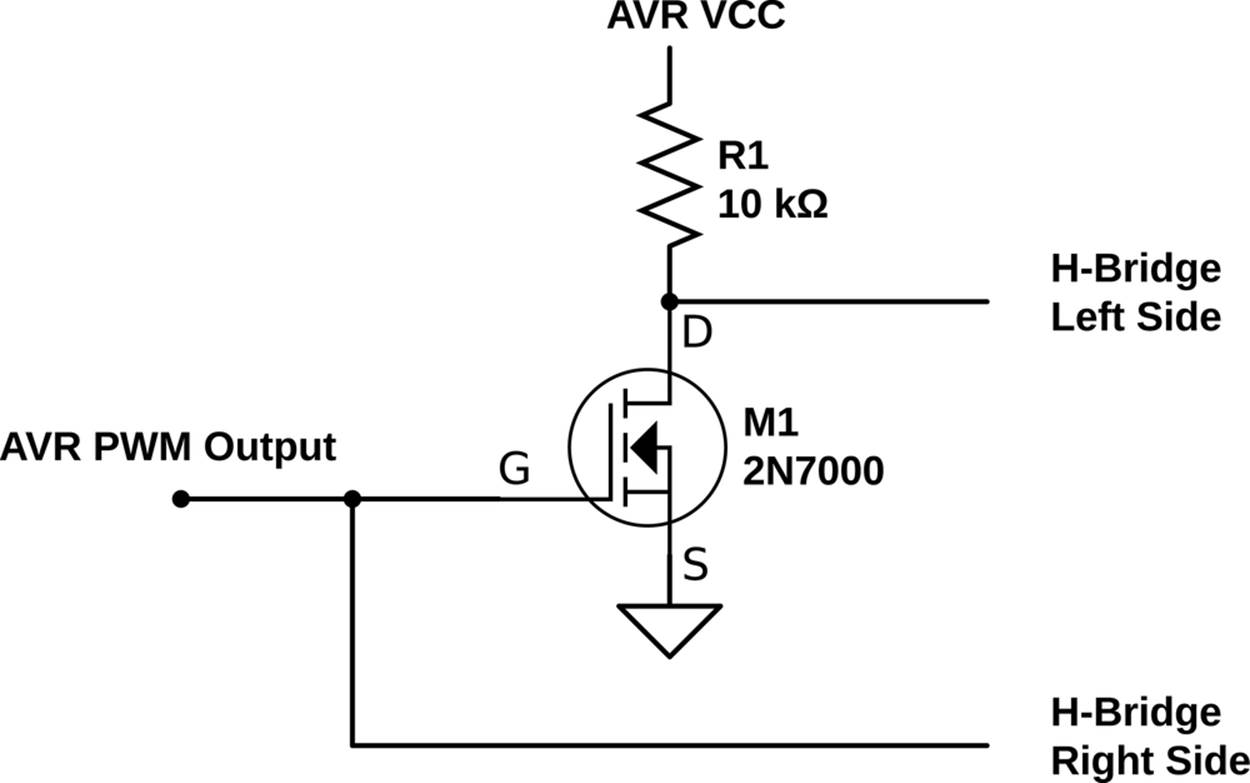
Figure 15-5. Locked anti-phase circuit
This circuit is a simple digital inverter—when the AVR’s output is low, the direct signal passed to the H-bridge’s right side is low. The voltage on the 2N7000 is also low, so it doesn’t conduct, so the wire leading to the H-bridge’s left side is pulled high. When the AVR pin is high, the 2N7000 conducts, pulling the left side low while the right side gets the direct high voltage.
The simplest way to control a locked anti-phase driver PWM bridge in code is to hook it up to a hardware-togglable pin and let the timer/counter module handle the rest for you. Your main code merely has to write the PWM value to the correct output-compare register.
Drive Modes: Comparison
Which of the possible drive modes is better? Well, as with everything, there are pluses and minuses to each. Locked anti-phase is simpler in that it only requires one wire between AVR and H-bridge, and that one timer/counter hardware PWM can handle everything for you.
The main problem with locked anti-phase drive is that, on startup, the motor is running at full speed in one direction or another until the AVR has gotten its PWM routine up and running to slow it down. This startup glitch is usually trivially short, but if your initialization routines take a long time to run, you might consider moving the motor-driver initializations to the top of your code. Similarly, if you accidently disable the timers, or you zap the AVR, or if the control signal wire comes unplugged, the motors run full speed ahead, which is definitely not what you want when something goes wrong. (Big robots must have kill switches attached to their power supplies.)
Secondarily, locked anti-phase mode keeps the H-bridge active and switching even while stopped, so it uses a little more power than sign-magnitude. It turns out not to be nearly as much as you might think, though. If you run the PWM at a high enough frequency, the motor windings end up building and collapsing magnetic fields and very little actual current flows; the motor doesn’t turn, and little power is lost. (A little bit of power is lost to the flyback diodes and FETs because of the unequal and not-exactly-instantaneous switching speeds of the FETs.)
One thing in sign-magnitude’s favor is that sometimes it’s conceptually natural to think of “shifting” into forward or backward first and then controlling the speed. If something goes wrong, the sign-magnitude drive style will usually end up with the motors stopped, which is a bonus. Finally, if your motors spend a lot of time stopped, sign-magnitude is a slightly better choice for power use.
COASTING
Our H-bridge in Figure 15-3 is a compromise design. In order to avoid the situation where both switches in a side are closed at the same time (which causes long-run shoot-through and catastrophic failure), we tied the P-channel and N-channel FET controls together. As a result, one (and only one) of the FETs on a side is conducting at any given time.
Though we need the one-FET-closed states, and it’s mandatory to avoid the both-FETs-closed state, the fourth state, both-FETs-open, is actually useful. When both of the switches on a side are open and not conducting, the motor can spin freely and coast. Access to a coasting mode allows another type of PWM, similar to our sign-magnitude drive, that alternates between drive and coast.
Because of this, most of the IC bridge chips offer an “enable” or “brake” line that will allow you to use both the braking mode we use here and the coasting mode where none of the FET switches are closed and you’re relatively free to push the motor around.
You can modify this circuit to enable coasting, but at the cost of another transistor or two, or other complexities. For a neat idea of how to do this with a quad opto-isolator instead of our 2N7000, see BJT H-Bridge.
H-BRIDGE CHIPS I HAVE KNOWN AND LOVED
One problem I have with recommending motor driver parts is that they’re in very active technological development at the moment. What was the best H-bridge driver three years ago isn’t the best H-bridge driver today, although some classics remain popular. Here’s a quick rundown of some available H-bridge silicon.
In the old days, for small loads up to 1 A, I would have recommended either the SN754410 or the L293D parts. I still have a soft spot in my heart for the SN754410, which builds four half-H bridges into one DIP part and has built-in flyback diodes. If you’re nearing the 1 A current limit, I recommended you take some of the heat load off the chip by providing your own diodes externally and/or paying attention to heat-sinking. The big drawback with the SN754410 and L293D is that they use Darlington transistors internally, so you have to count on losing 1–2 V on the high side and the low side at higher currents. Because of this voltage drop, you’ll want to run your application with a higher-voltage motor and battery for efficiency’s sake. With that one drawback, the SN754410 is a complete two-motor solution for around a US dollar in a handy chip format. You should have a couple of these in your parts drawer. I’ll use this chip to drive stepper motors in Stepper Motors.
Competing with the SN754410 on the low-voltage, lower-amperage side of the market are a bunch of MOSFET-based surface-mount devices that are intended for driving toys or other small motors. The DRV883x family from TI and the A3959 and A495x series from Allegro Micro all offer 1–2 A MOSFET designs in tiny, tiny little packages. Because of their small size, these are not necessarily easy to solder together, but you can do it with practice. Or you can buy motor-driver breakout boards from hobbyist-friendly shops like Sparkfun or Pololu.
For medium-sized motor loads, the next step up on current-handling is another old classic—the L298 driver. The L298 is good for a max of 3 A, at a cost of around $5. This is one of the most popular motor drivers of all time, and is also a Darlington-based design, with all the accordant drawbacks. They have a strange pinout but are very easy to mount to a heatsink, which you’ll need if you’re going to use them above 2 A. The L298 is such a classic that I can’t fail to mention it, but I would rather spend a little more money on a modern chip.
Above 5 A or so, you’re going to want a MOSFET design. Because DC motors are used in cars to adjust seats and drive fans and so on, there’s a variety of motor drivers that drive tens of amps at 12 V. The VNH2SP30 from ST is surface-mount, but not tiny, and includes all the bells and whistles you could want from a motor driver. The BTN7960 from Infineon is a similar half-bridge, so you’ll need to buy one chip for each side of the H-bridge, but they come in larger packages and may be easier for you to work with. If you’re pushing either of these drivers anywhere near their limit of 30 A, you will need a small fan for cooling in addition to a heatsink. You’ll probably also want to use thick wire.
At really high current levels, you’ll want to build your own H-bridge. Because N-channel FETs switch faster and have lower losses than their P-channel cousins, high-current bridges are almost exclusively built from N-channel MOSFETs, even on the high side. This means generating a control voltage for the high-side FETs that is higher than the battery supply by 5 to 10 volts. Because this quickly becomes a design hassle, there are dedicated MOSFET driver chips that provide voltage-doubled, high-side switch drivers and prevent shoot-through and limit maximum current, all in one IC. With one of these chips plus two N-channel MOSFETs, you’ve got one half of a bridge. Duplicate the circuit again, and you’ve built a full bridge with all the bells and whistles of an integrated solution, but without any of the power limitations. Now you can build that autonomous electronic forklift you’ve been thinking about.
Stepper Motors
Stepper motors can provide high positioning accuracy like a servo, while being able to rotate continuously like a normal DC motor. Stepper motors are found inside things like printers and scanners, where it’s important to be able to repeatedly move a very precise distance (say, 1,200 dots per inch). Stepper motors have two distinct sets of coils inside them and get the name “steppers” because they rotate a fixed number of degrees each time the magnetic fields reverse in the coils.
Brushed (regular) DC motors have a pair of flexible conductive brushes that make and break connections for the two coil windings inside as they turn, constantly reversing the polarity of the magnetic field induced in the coils. The connections are precisely aligned; just as the electromagnets have pulled themselves close to the permanent magnets in the shell, the electromagnets’ polarity is switched and they repel themselves away from the same permanent magnet. Getting this timing/positioning just right makes the motor spin on its own even with DC applied to the motor’s two terminals. You apply DC voltage, but the brushes periodically reverse the direction that this current flows through the internal electromagnets, making the motor turn.
Stepper motors have no brushes. You’re expected to know when to switch the current one way or the other through the coils. The great advantage of stepper motors is that you can control when it takes a step, and how many it takes, by controlling these coil currents. This means that your microcontroller can count up how many steps the motor has taken and know exactly where the motor shaft is currently pointed.
But if you thought it was a pain to have to use an H-bridge in the previous section, you’re not going to like the fact that most steppers require two H-bridges to drive: one for each coil winding. If you’re building a system with a bunch of stepper motors in it, each with two H-bridges to drive it, you’ll get tired of hand-tuning H-bridges pretty quickly. In this chapter, I’ll use a common dual H-bridge driver chip, the SN754410.
Even using a dual H-bridge chip is taking a fairly low-level approach these days. There are a few dedicated stepper-motor driver chips out there that do all sorts of useful and complicated things for you, not the least of which is enabling you to take even smaller, smoother steps than we’ll be able to here. These chips take a load off of your microprocessor by incorporating some of the driving logic and the two H-bridges in one. On the other hand, you can do a lot with a simple dual-H driver chip, and you’ll get a better feel for what’s really going on.
Kinds of Stepper Motors
There’s quite a variety of different stepper motors out there, but I’ll be focusing on the most common type that you’re most likely to see and use: a hybrid stepper with 200 steps per revolution, driven in bipolar mode.
Hybrid stepper motors have both permanent magnets and electromagnets on the rotating core. This gives the stepper motor a bit of a pull toward fixed detent positions when no current is applied, but with enough current, the motor can rotate itself out of one detent state into the next. These detents make it much more likely that the motor will take one and only one step when driven in full-stepping mode; plus they give the motors some holding torque when all electrical power is turned off.
Bipolar stepper motors rely on you driving the poles of the electromagnets one way and the other via something like an H-bridge. We’re going to drive current back and forth through the whole coil—bipolar style.
Finally, most steppers have 200 steps per revolution, though you’ll find that especially cheaper and smaller ones sometimes have fewer steps per revolution. You can also buy 400-step steppers if you want to. If you need more resolution or smoother rotation, you can use microstepping, a PWM-like technique, to drive the motor between steps. We’ll discuss microstepping in detail in Microstepping.
Figure 15-6 is a diagram of a four-step-per-rotation stepper motor’s insides. The central core is a permanent magnet attached to the shaft, with its north pole pointing in the direction of the arrow. Around the outside are four coils, arranged in two pairs. When current flows from 1A to 1B, for instance, the two coils become electromagnets with their north poles pointing to the left, in the direction of the arrows. Because the north pole of the magnet on the shaft is attracted to the south poles and repelled by the north poles of the surrounding electromagnets, it will turn until the shaft’s north pole is halfway between the two south coil poles.
In a stepper motor with 200 steps per rotation, the permanent magnet attached to the rotating shaft and the coil magnets on the outside of the case both have many teeth that are slightly offset from one another. Instead of the motor shaft turning 90 degrees to align up between the nearest coil magnets, it only turns 1.8 degrees. The principle is the same, however, and I find the simpler four-step analogy more useful.
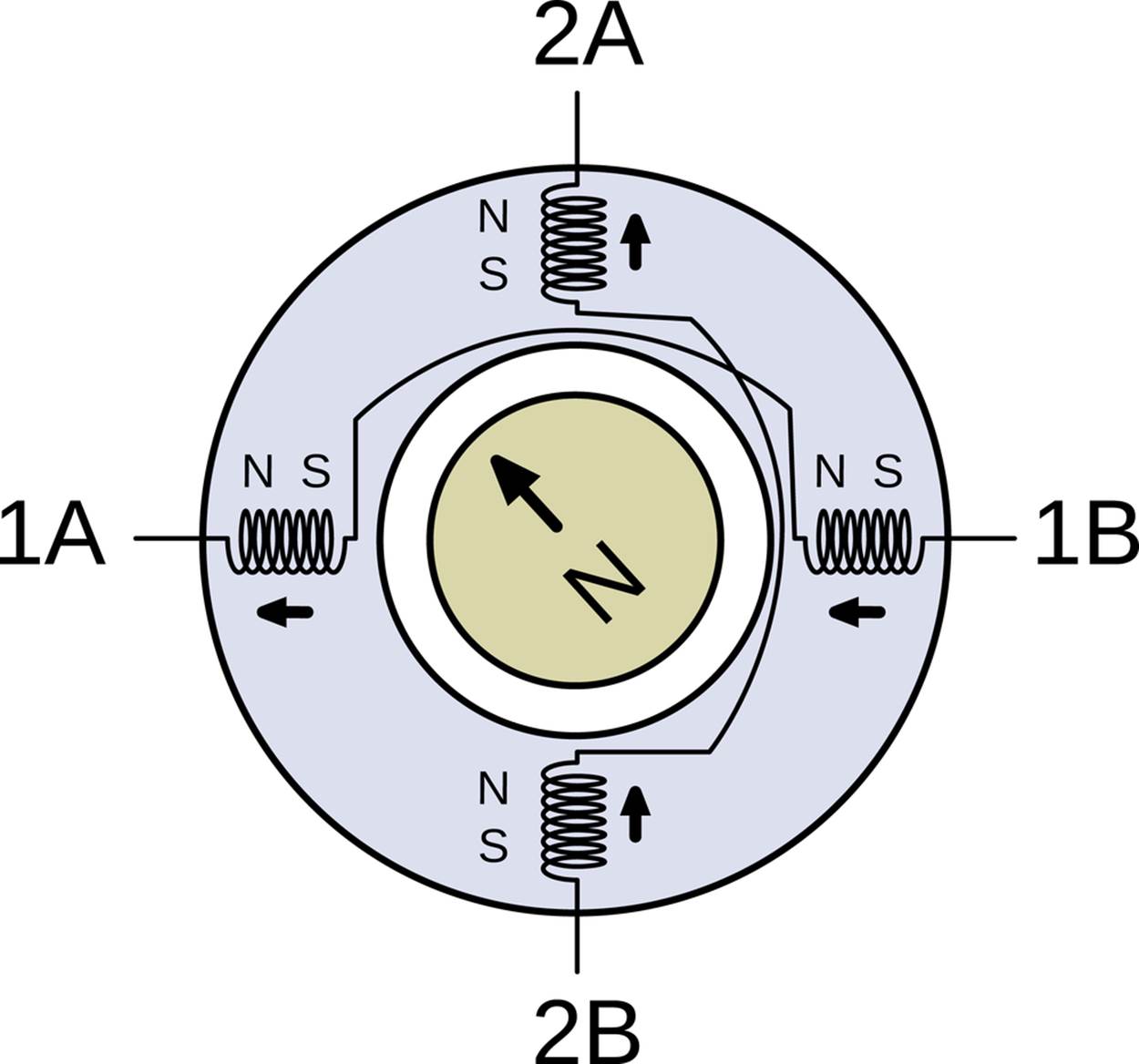
Figure 15-6. Stepper motor inside
Full Stepping and Half Stepping
Now that we know how a stepper motor is built and what makes it rotate, let’s look in detail at how we can drive it.
The simplest way to drive a stepper motor is in full steps. In full stepping, both of the coils are energized all the time, so both electromagnetic fields are pulling all the time on the permanent magnets attached to the motor shaft. If you change the coil-driving voltages around in the right way, you can get the motor to spin. See Figure 15-7.
Looking at the diagram, starting from the upper left and going clockwise, you can see the pattern of coil voltages required to spin the motor shaft clockwise. Going from the top-left state to the top-right state requires reversing the voltage on the horizontal coil pair. Then to take the next step, you reverse the voltages on the vertical pair. Following this cycle, changing the polarity of one coil first, then the other, will make the stepper motor rotate.
Also note that if you start off by changing the voltages on the vertical pair first, you move down to the lower-left motor state. Turning the stepper motor counterclockwise is simply a matter of moving through the same pattern of driving voltages the other way around.
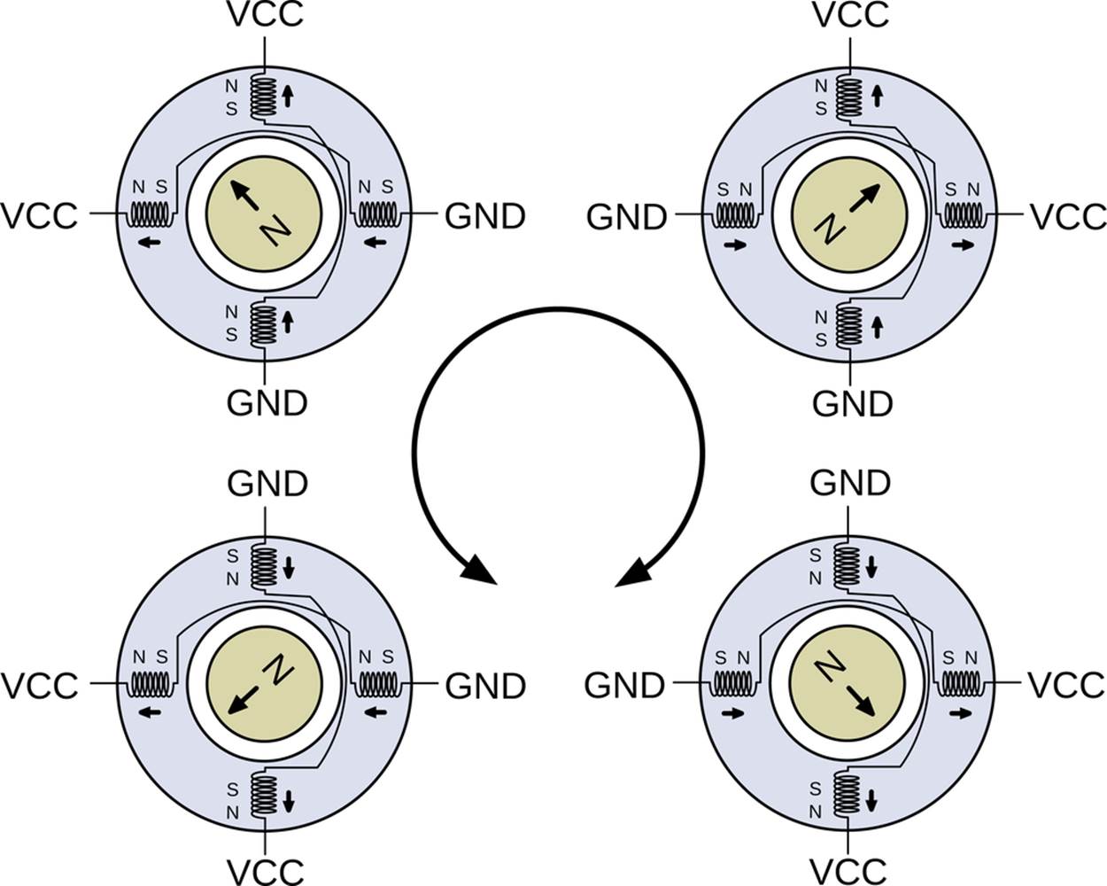
Figure 15-7. Full steps
Half stepping is a simple variation on full stepping. Instead of having all coils energized all the time, half of the time one coil pair is turned off, causing the rotating magnet to point directly at the coil that it’s most attracted to. This way, you get eight steps per cycle instead of four, or 400 steps per rotation instead of 200.
To see how half stepping works, we’ll insert a step between the upper-left and upper-right full-stepping states. See Figure 15-8.
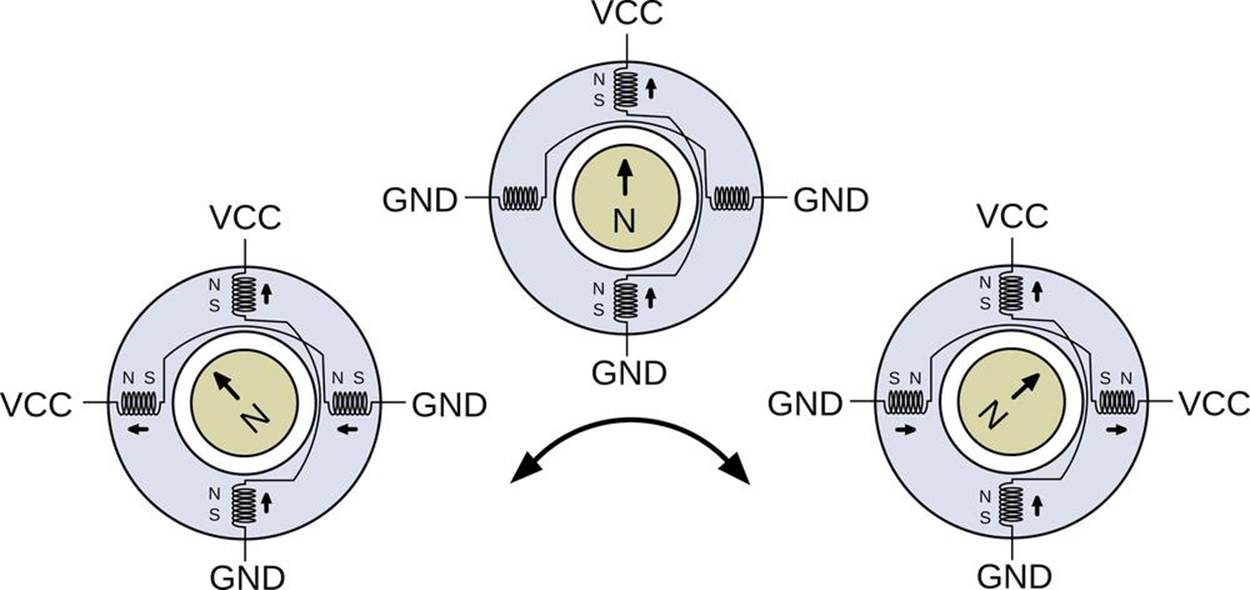
Figure 15-8. Half steps
If we were full stepping, the first step to turn the motor clockwise would be to reverse the polarity on the horizontal coil pair. To take a half step, we first simply turn off the horizontal coil pair, either by driving both ends of the coil at the VCC or GND voltages. The north pole of the rotating magnet then points straight up, at the south pole of the still-energized vertical pair, and the motor’s shaft has turned 45 degrees counterclockwise. The next half step, then, is to reenergize the horizontal coil pair, but in the opposite polarity of the initial state.
In summary, to go from full steps to half steps, instead of simply reversing each coil’s current, you take an intermediate step where you turn off that coil first. See Table 15-4 if you’d like to see that written out in a table. (And notice that you can get the full-stepping pattern simply by skipping the odd-numbered phases.)
Table 15-4. Half-stepping coil currents
|
Phases |
Coil 1 |
Coil 2 |
Degrees rotation, 4-step motor |
Degrees rotation, 200-step motor |
|
0 |
+ |
+ |
0 |
0.0 |
|
1 |
+ |
45 |
0.9 |
|
|
2 |
- |
+ |
90 |
1.8 |
|
3 |
- |
135 |
2.7 |
|
|
4 |
- |
- |
180 |
3.6 |
|
5 |
- |
225 |
4.5 |
|
|
6 |
+ |
- |
270 |
5.4 |
|
7 |
+ |
315 |
6.3 |
|
|
0 |
+ |
+ |
360 |
7.2 |
Identification of Stepper Motor Wires
The stepper essentially has two electromagnet coils inside it, and if you’ve got a bipolar stepper motor, you’re probably looking at four wires sticking out. Two of these wires are the ends of one coil, and two are the ends of the other. Now you need to figure out which is which. I’ll show you three ways, and there are probably more.
The first is to simply hook up an ohmmeter to two wires arbitrarily. If you get wire-ends from two different coils, they should be not connected. When you get a pair from the same coil, you will be able to read off the coil resistance in ohms. Write this down somewhere. And while you’re at it, write down which colors are common to a coil.
If you already know the coil resistance, one neat way to figure out the pairing scheme is to connect an LED across two wires, spin the motor shaft, and see if the LED lights up. If it does, you’ve found a coil pair and demonstrated that a stepper motor can be used as a generator. The spinning magnets inside the stepper make an alternating current in the coil as the north and south poles on the rotor swing past.
The final way to figure out the coil pairing is to connect the wires together pair-wise. For instance, connect wire one with wire two, and separately connect wire three to wire four. If it is hard to turn the motor, you’ve got the pairings right. If you switch the connections (one to three, two to four) you should be able to turn the motor freely. What’s happening is that when you short out the coils, the generated electricity creates a magentic field inside the motor that opposes your turning it. Remember with DC motors how the speed was limited by the generator voltage equalling the driving voltage? When you try to turn a shorted stepper motor, you’re fighting this generator voltage.
Anyway, if you’ve done any or all of the three experiments, you’ll have a good feeling for some of the internal physics of stepper motors and you’ll know which wires form the two coil pairs.
Too Many Wires!
If you’ve got a motor with five, six, or eight wires coming out of it, don’t fret. Consult Figure 15-9 to see what’s going on inside the motor.
If your motor has five or six wires, you can use an ohmmeter to find the pair ends. Looking at Figure 15-9, you’ll notice that the coil resistance between a center tap and any of the coil ends will be half of the resistance across two coil ends. For instance, a six-wire motor on my desk has roughly 5 ohms of resistance per coil, so the end-to-end resistance between the end wires is 10 ohms. Once you’ve found the two pairs with 10 ohms resistance between them, you’re done. You can ignore the extra two center taps.
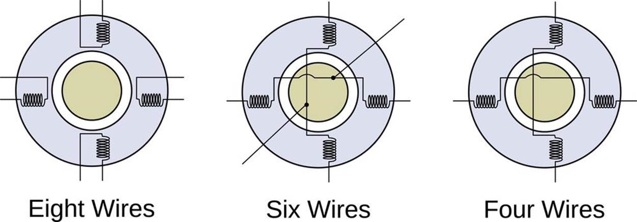
Figure 15-9. Possible stepper motor wiring patterns
Most five-wire steppers are essentially the same as six-wire motors, except the two center tap wires are connected together inside the motor body. Just as with six-wire motors, the center tap will show half of the resistance to other wires on an ohmmeter. Ignore it and you’re done.
CENTER TAPS, UNIPOLAR MOTORS
In the case of five- or six-wire steppers, the extra wires tapped off between the coil pairs enable you to drive the motor without using an H-bridge by supplying a high voltage to the center tap and alternately grounding either end of the coil pair to activate it. This style of motor and drive are both referred to as unipolar, because each individual coil is only ever being driven with one polarity: high voltage in the center and ground on the coil end.
Because you can choose to ignore the center taps, a unipolar stepper can always be driven as if it were a bipolar motor. The reverse isn’t true, of course.
If you’ve got a stepper with eight wires, a bifilar stepper motor, you’ve got your work cut out for you! It’s fairly easy to figure out which four pairs of wires are connected together with an ohmmeter, and in principle you can just connect up the four wire ends together in pairs to mimic the wiring of the four-wire, bipolar, stepper motor. But now you face two problems: you don’t know which coils are on opposite sides of the motor, and then you don’t know which wires to connect to get the two opposite coils in the same polarity. If you’re really determined to drive a bifilar stepper motor, there are 12 ways to connect the wires up, and two of them will work. Grab a cup of patience and take good notes.
Dual H-Bridge Chips: The SN754410
So you’ve just figured out which two pairs of wires correspond to the inner coils that spin your stepper motor. Now we need to hook each coil up to an H-bridge circuit so that we can charge up the coils in either polarity; applying a positive driving voltage on one side and then on the other, just like we did with the DC motor earlier.
The chip we’re using for this project actually consists of four half-H-bridges. That means that each side of the “H” can be driven to the high or low voltage independently, just like our demo H-bridge could. We’ll control the four half-H sides with four wires from the AVR. Each one sets an “H” side to high or low drive voltage, respectively. Once we’ve hooked up the stepper motor’s two coils to the four H-halves, we’ll be able to run current one way through the coil by setting one AVR pin high and the other low, and then reverse the current flow (and the sense of the electromagnetic field) by setting the first pin low and then the other high.
Each half-H is “smokeless” in the sense that when it sees a logic high voltage, it connects only its high-side switch internally, and vice versa for logic low. If we set both sides of the same coil (and the same “H”) high or low, no current flows through the coil unless the motor is being turned externally. It’s like the previous example where we shorted the two coil ends together.
Let’s have a look at the SN754410 chip’s pinout in Figure 15-10 and make sure that we understand how everything works. If you’d like to read along in the chip’s datasheet, go right ahead.
The pins labelled “1 Out” and “2 Out” are the left and right halves of a complete H-bridge. The corresponding “In"s control the voltage on the “Out"s. There’s additionally a “1,2 Enable” line which, when held at the logic high voltage, enables the driving transistors on the “1,2” side. Disabling the H-bridge means that all of the driving switches are open, and it’s as if the motor were entirely unconnected. Whenever the H-bridge is enabled, the two outputs are pulled either high or low through the bridge’s transistors.
You’ll notice that there are also two VCC voltage supply pins. One is for the logic-level voltage that you connect to the AVR, and the other is for the high voltage level that you’d like to use to drive your motor. In the case of the SN754410 you can use up to 36 V, depending on your stepper motor.
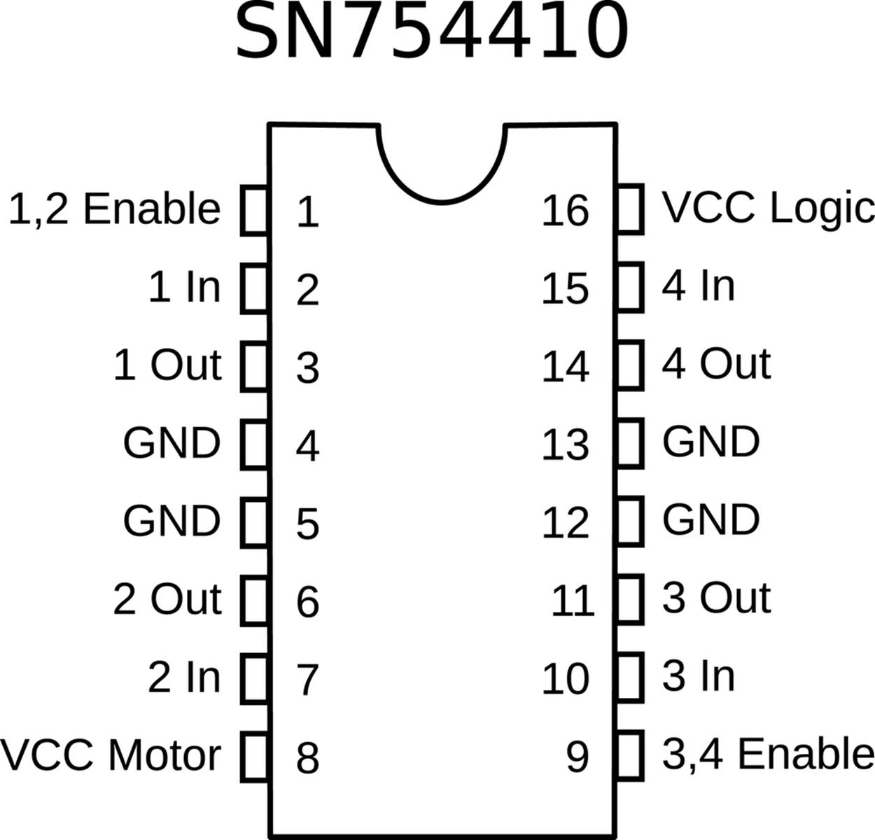
Figure 15-10. SN754410 pinout
Finally, you’ll notice that there are four ground pins. They are all connected together internally, and are additionally connected to the chip’s internal heat sink. The idea is that, if you’re making your own printed circuit board, you can connect the ground to a large piece of copper on your PCB, which will act as a radiator to help cool off the chip. Without this additional heat-sinking, the chip’s maximum current rating of 1 A continuous is a bit ambitious, and you’ll note that the chip can get hot to the touch in use. If it gets too hot (burning-your-finger hot) you should be ready to disconnect the motor VCC as quickly as possible—you can burn these chips out if you’re drawing too much current.
Now let’s hook up the AVR, the SN754410 motor driver, and the stepper motor all together. See Figure 15-11 for an example.
My stepper motor is rated for 11 V DC, it says, so a 9 V battery gets it in the right ballpark. If your stepper is rated for any other voltage, connect this supply up to pin 8 as in the diagram. Note that if you connect the stepper to the same power supply as the AVR, the stepper motor might draw enough current to drop the voltage down on the AVR, causing it to be unstable. That’s why these motor drivers come with separate power supplies for the logic and motor sections.
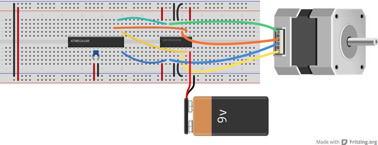
Figure 15-11. Stepper motor and H-bridge
Hook up the two wires that are common to one coil to one side of the SN754410 so that they’re connected to the same H-bridge. In my example, the blue and yellow wires form one coil and the orange and green wires form the other. Which one of the two wires you designate as “1” or “2” is irrelevant. You can swap them around once you get the software running, and getting it “wrong” just means the motor will rotate counterclockwise where you think it should be clockwise. Now connect the other pair to the other side—outputs “3” and “4.”
Connect the logic power and the two enable lines to the AVR’s breadboard VCC rail (and notice that I jumpered it across to make the wiring simpler). Connect up the grounds to ground. At least one of these must be connected. The others are optional.
Now run wires to the AVR’s pins PB0, PB1, PB2, and PB3. If you’ve still got your LEDs hooked up to these pins, feel free to leave them in. They won’t interfere with the logic levels for the motor driver chip, and they’ll give you some nice visual feedback about which coil phases are currently energized.
Make sure that PB0 and PB1 go to one side of the chip (the same H-bridge) and that PB2 and PB3 go to the other side. If you swap PB0 for PB1, the motor will run the other direction, but if you swap PB0 with PB2, the motor won’t run.
Once you’ve got the stepper motor and driver connected, you’re ready to run some code.
The Code
To drive the stepper motor forward, say, we’ll need to energize and deenergize the coils in the motor in a given pattern at a given rate. This suggests that we store the stepping pattern in an array and then just step through it with an indexing variable. To take steps at a regular speed, we can use a timer/counter set in compare-match mode to handle the variable timing and an interrupt to do the work of setting up the AVR’s output pins. And then once that framework is set up, we can do something elaborate with it. We’ll start off with the code in Example 15-2.
Example 15-2. Partial stepperWorkout.c listing
/* Stepper Motor Demo with Accelerated Moves */
// ------- Preamble -------- //
#include <avr/io.h>
#include <util/delay.h>
#include <avr/interrupt.h>
#include "USART.h"
/* Set these to +/- 1 for half-stepping, +/- 2 for full-stepping */
#define FORWARD 1
#define BACKWARD -1
#define TURN 400 /* steps per rotation,
depends on stepping & motor */
/* These parameters will depend on your motor, what it's driving */
#define MAX_DELAY 255 /* determines min startup speed */
#define MIN_DELAY 8 /* determines max cruise speed */
#define ACCELERATION 16 /* lower = smoother but slower accel */
#define RAMP_STEPS (MAX_DELAY - MIN_DELAY) / ACCELERATION
// -------- Global Variables --------- //
const uint8_t motorPhases[] = {
(1 << PB0) | (1 << PB2), /* full */
(1 << PB0), /* half */
(1 << PB0) | (1 << PB3), /* full */
(1 << PB3), /* half */
(1 << PB1) | (1 << PB3), /* etc. */
(1 << PB1),
(1 << PB1) | (1 << PB2),
(1 << PB2)
};
volatile uint8_t stepPhase = 0;
volatile int8_t direction = FORWARD;
volatile uint16_t stepCounter = 0;
// -------- Functions --------- //
void initTimer(void) {
TCCR0A |= (1 << WGM01); /* CTC mode */
TCCR0B |= (1 << CS00) | (1 << CS02);
OCR0A = MAX_DELAY; /* set default speed as slowest */
sei(); /* enable global interrupts */
/* Notice we haven't set the timer0 interrupt flag yet. */
}
ISR(TIMER0_COMPA_vect) {
stepPhase += direction; /* take step in right direction */
stepPhase &= 0b00000111; /* keep phase in range 0-7 */
PORTB = motorPhases[stepPhase]; /* write phase out to motor */
stepCounter++; /* count step taken */
}
void takeSteps(uint16_t howManySteps, uint8_t delay) {
UDR0 = delay; /* send speed/delay over serial, non-blocking */
OCR0A = delay; /* delay in counter compare register */
stepCounter = 0; /* initialize to zero steps taken so far */
TIMSK0 |= (1 << OCIE0A); /* turn on interrupts, stepping */
while (!(stepCounter == howManySteps)) {;
} /* wait */
TIMSK0 &= ~(1 << OCIE0A); /* turn back off */
}
int main(void) {
// -------- Inits --------- //
initUSART();
_delay_ms(1000);
initTimer();
DDRB = (1 << PB0) | (1 << PB1) | (1 << PB2) | (1 << PB3);
// ------ Event loop ------ //
while (1) {
direction = FORWARD;
takeSteps(TURN / 2, MIN_DELAY * 2);
_delay_ms(1000);
direction = BACKWARD;
takeSteps(TURN, MIN_DELAY);
_delay_ms(1000);
direction = FORWARD;
takeSteps(TURN / 16, MAX_DELAY);
direction = BACKWARD;
takeSteps(TURN / 8, MAX_DELAY / 2);
direction = FORWARD;
takeSteps(TURN / 16, MAX_DELAY);
_delay_ms(1000);
} /* End event loop */
return (0); /* This line is never reached */
}
As I suggested earlier, most of the heavy lifting in this example is done with a timer/counter and some global variables, so that’s a good place to start our analysis. The constant array motorPhases[] contains the bit values that we need to energize the motor coil windings and is arranged in the right order to make the motor turn one direction. For concreteness, let’s say that the horizontal coil in the motor is connected through the H-bridge to the AVR pins PB0 and PB1. When you set PB0 high and PB1 low, the coil is energized with one polarity, and when PB1 is high and PB0 is low, the other polarity.
The current position in the motor phase table is stored in the global stepPhase. There is code inside the ISR to keep stepPhase within the range of the motorPhases[] table. The direction that the motor should turn is stored in direction and an overall counter of how many steps have been taken is stored in stepCounter.
The ISR that uses these global variables is short and sweet. First the stepPhase is incremented or decremented depending on the value of direction. stepPhase &= 0b00000111; makes sure that we’re keeping the steps in the range zero to seven so that it never overflows the motorPhases[] lookup table. Finally, the ISR sets up the output on PORTB according to the current stepping phase and increments the step counter. If we let the counter and ISR free-run, the motor would turn at a speed determined by the frequency of compare-match interrupts coming from the timer.
And speaking of timer initialization, it’s is a totally standard “clear timer on compare match” (CTC) setup, where the delay between steps is set using the OCR0A register that the timer counts up to. The only thing noteworthy here is that, although we set up the global interrupt enable bit, the code doesn’t enable the specific compare-match interrupt just yet. As soon as the interrupt is enabled, the ISR code will run and the motor will start spinning. We’re not ready for that yet.
Next, let’s look at the takeSteps() function that’ll actually do something for us. Basically, it simply uses this timer/counter and ISR framework that we’ve just set up. We specify how many steps we’d like the motor to take and the delay between steps that determines the rotation speed, and the routine makes it happen.
For fun, and for your intuition about what’s going on, the takeSteps() function starts off by sending the current delay value out over the serial line. Later, when we implement complex movements that speed up and slow down, you can watch this output change on your computer using something like our serialScope.py application.
The rest of the code does the real work. The delay value is written to the output-compare register for Timer 0, the stepCounter is reset, and then the output compare interrupt enable bit (OCIE0A) is set. At this point, the ISR will start firing and the motor will start turning at the specified speed. Because the ISR increments the stepCounter with every step, all that remains is for us to wait until it reaches the desired value, and then turn off the compare interrupt to shut the motor off.
That’s all you need for simple stepper motor control. If you’re interested in seeing what you can do with just the basics, flash in the code example with the shortened version in Example 15-2. (make flash MAIN=stepperWorkout_short.c should work.)
Acceleration Control
The problem with our naïve demo based simply on the takeSteps() routine is that we’re telling the motor to start up at full speed, take a bunch of steps, and then stop instantaneously. If the stepper motor is strong enough and your load light enough, you can get away with these jerky, start-stop movements. But it’s equivalent to driving by flooring either the gas or brake pedal. This style may be OK for Formula One races, but it’s tough on the car, the environment, and the passengers. And with stepper motors, this can lead to missing steps.
To see how steps get missed, it’s worthwhile to think of the stepper motor shaft and motor coils as two distinct parts of your motor system. Under light loads and at low speeds, the motor shaft catches up almost instantly when you advance the phase of the driver and the coils. As you speed up the driver or increase the inertia of the motor’s load, the motor shaft phase can start to lag behind the coil phase. If you try to spin the motor faster and faster, eventually you’ll get to the point where the shaft phase gets more than one step behind the driver and coils. (Try it! Add takeSteps(TURN, 2); to the code and see what happens.)
Look again at the single-stepping diagram in Figure 15-7. If the motor’s shaft lags more than one step behind the driver when you are full-stepping, the coil ends up pulling it in the direction that’s exactly opposite of the direction you’d like it to be turning. This can cause missed steps, a nasty grinding noise, and all of a sudden your AVR chip doesn’t know where the motor is pointing any more because it thinks it has taken steps but the motor didn’t turn.
A better idea is to ramp up the speed, from slowly moving to full speed ahead. Taking a little more time per step at the beginning gives the motor shaft more time to catch up to the driver’s phase, and helps to prevent missed steps. Once your heavy load has started to turn, you can speed the motor up. And of course you’ll want to ramp the speed back down again in anticipation of stopping. Ramping the speed up and down like this allows you to run the motor at a higher cruising speed than you would otherwise be able to start the motor off with, and it makes for smoother motion control and less stress on moving parts. It’s a win all around.
In the demo code, I implement an acceleration profile that’s particularly easy to code up and understand, yet performs pretty well in the real world. Motion control turns out to be a deep subject, and if you know a lot about the geometry and masses of your particular setup, you can probably optimize this code for your situation. This is particularly true if you’re planning a complicated path where you don’t necessarily want to stop the motor fully between movements. Still, try this code snippet first for generic situations.
We assume that the motor is initially stopped and that we’d like it to be stopped again but having rotated through a given number of steps as fast as possible. We’ll model the movement in three stages: an acceleration stage, a cruising stage where the motor runs at maximum speed, and a deceleration stage. If the number of steps is too few to reach maximum speed and decelerate back down in time, we speed up as much as possible and then immediately start ramping back down. Let’s see how that works in Example 15-3.
TRAPEZOID SPEED PROFILE
I’m calling this speed profile “trapezoid” because the speed per step increases linearly up to the maximum speed, holds steady, and then decreases linearly per step until it’s stopped. Thus, the velocity is a linear function of the number of steps—the position.
But because each step takes less time than the previous one, the velocity is not a linear function of time, so this isn’t a constant acceleration curve—the acceleration is also an increasing function of time during the ramp-up stage.
Example 15-3. stepperWorkout.c trapezoidMove() listing
void trapezoidMove(int16_t howManySteps) {
uint8_t delay = MAX_DELAY;
uint16_t stepsTaken = 0;
/* set direction, make howManySteps > 0 */
if (howManySteps > 0) {
direction = FORWARD;
}
else {
direction = BACKWARD;
howManySteps = -howManySteps;
}
if (howManySteps > (RAMP_STEPS * 2)) {
/* Have enough steps for a full trapezoid */
/* Accelerate */
while (stepsTaken < RAMP_STEPS) {
takeSteps(1, delay);
delay -= ACCELERATION;
stepsTaken++;
}
/* Cruise */
delay = MIN_DELAY;
takeSteps((howManySteps - 2 * RAMP_STEPS), delay);
stepsTaken += (howManySteps - 2 * RAMP_STEPS);
/* Decelerate */
while (stepsTaken < howManySteps) {
takeSteps(1, delay);
delay += ACCELERATION;
stepsTaken++;
}
}
else {
/* Partial ramp up/down */
while (stepsTaken <= howManySteps / 2) {
takeSteps(1, delay);
delay -= ACCELERATION;
stepsTaken++;
}
delay += ACCELERATION;
while (stepsTaken < howManySteps) {
takeSteps(1, delay);
delay += ACCELERATION;
stepsTaken++;
}
}
}
Because we want the motion profile to be the same whether we’re spinning the motor clockwise or counterclockwise, we can set the direction global variable at the beginning of the routine and convert the number of steps into a positive number.
The minimum and maximum delays, which are the inverse of the speed, are set in define statements at the top of the program, as is the acceleration, how much to reduce the delay per step. This means that the number of steps needed to complete an acceleration or deceleration ramp is fixed and can also be computed in a define (RAMP_STEPS).
Because everything is precomputed, the trapezoidMove() routine just has to figure out if it has enough steps to spend some time cruising at the maximum speed—if the number of steps to take is longer than two ramps—or whether it should go straight from acceleration to deceleration. In the first case, the routine loops through a series of single steps at increasingly small delays and counts the steps taken as it goes along. The cruising stage is implemented with a single call to takeSteps() at the maximum speed: setting the delay to the defined MIN_DELAY. Finally, the deceleration phase is a single-step loop that’s the mirror image of the acceleration stage.
When there are not enough steps desired to reach maximum speed, and thus cruise, the routine is even simpler. The acceleration stage lasts for half of the steps, and takes single steps more and more quickly. At the halfway point, it’s time to start decelerating again, and the deceleration routine just adds to the delay with each step until it’s done.
Microstepping
Compared to taking full steps through the motor’s rotation, taking half steps gains us higher spatial resolution and helps to smooth out the discrete steps, which can cause jerkiness at low speeds and excess noise at high speeds. You might be wondering if it’s possible to take this further. Of course it is! But it’s not easy.
Microstepping lets you drive a stepper motor to intermediate positions between the half steps by controlling the ratio of coil currents in the two coil pairs. You can control the coil currents by using PWM, changing the driving voltage, or using other current-limiting circuits, but the basic idea is that by varying the magnetic pull on the rotor coming from the two coils you should be able to make the motor move to any angular position you’d like. Figure 15-12 shows an example of the voltages you’d use to get quarter-step microstepping. Perhaps it’s easiest to think of controlling the average driving voltages by using something like PWM, and you can certainly do just that.
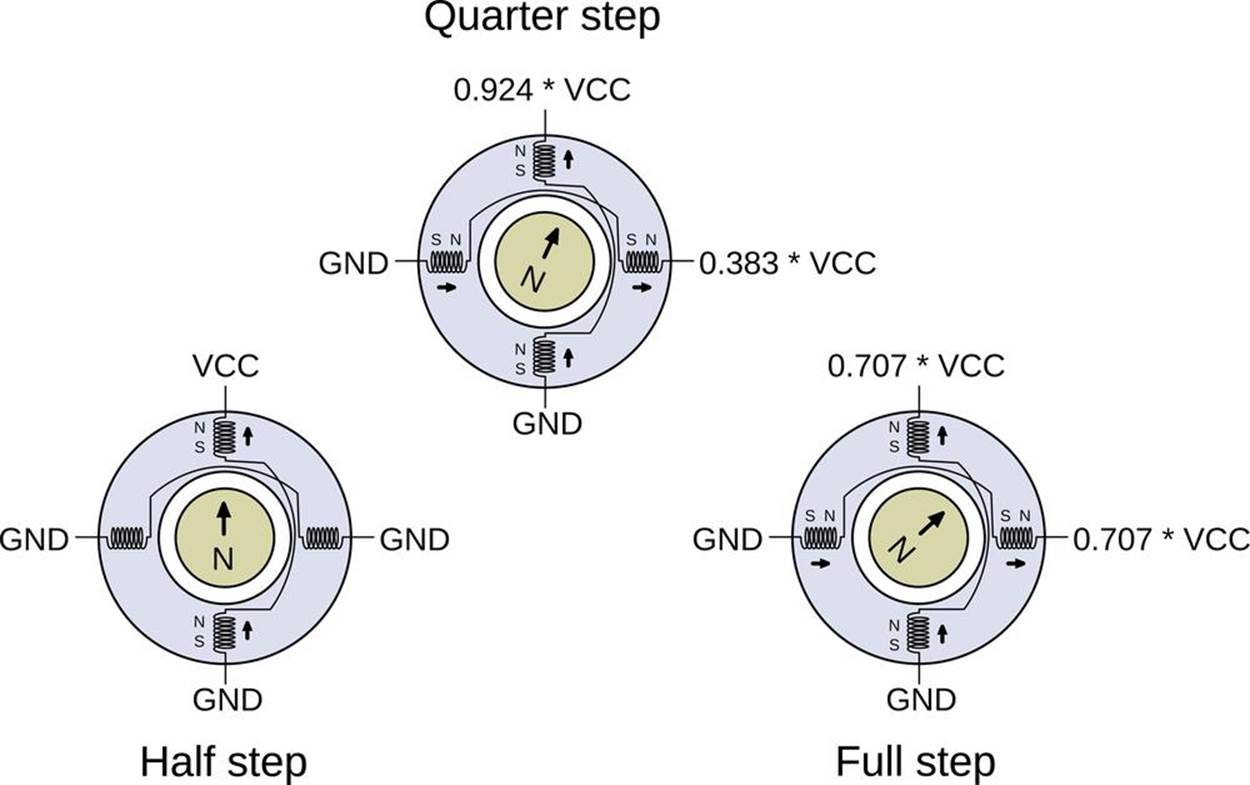
Figure 15-12. Equal power microstepping example
We already know that when only the vertical pole is full on, the rotor will align so that its magnet’s north pole points straight up. We also know that when both of the coils are equally on, the rotor points to the 45 degree position. If we slightly increase the duty cycle for one coil pair and slightly decrease the duty cycle of the other, the rotor should turn a tiny bit and end up somewhere between the half-step and quarter-step positions.
EQUAL POWER MICROSTEPPING
The mathematics isn’t pretty, but it’s not really more than a little physics and some trigonometry. We want to figure out how much power we need from each coil pair for a given angle, holding the total power constant around the circle.
Power is a function of voltage (or duty cycle) squared, so adding up the duty cycles from the two coils is like adding up lengths of legs of triangles. That means the duty cycles that we’d need to use are sine and cosine functions of the desired rotation angle. Easy, right?
In contrast, when we implemented half stepping we were not keeping the power constant as we rotated the motor around the circle. In fact, the motor pulled 1.414 times stronger when both coils were on than it did with just one on. We’d need to throttle the two phases back by a factor of sin(pi/4) or 0.707 when they’re both on to maintain equal power around the cycle.
Whether or not this is a good thing depends on your application. The slightly uneven power cycle of regular half stepping makes it a little bit noisier than it would be under equal-power half stepping, but when both coils are fully engaged, the motor has roughly 40% more torque. Most microstepping chips will aim for equal power, so you’ll be losing some of your possible motor torque. The way we implemented half stepping is both the easiest and gets the maximum performance out of a given voltage source, at the expense of being a little “jerkier.”
Now, it would be possible to calculate all of the sines and cosines ahead of time, store them in a table in memory, and then use the built-in PWM hardware (conveniently, there are two compare values per timer!) to implement microstepping on your own with our SN754410 H-bridge. If you’d like a challenge after this chapter, I recommend it as a good learning experience.
On the other hand, if you’d like to simply use microstepping and stepper motors rather than learning something, I honestly have to recommend buying an integrated indexer and driver chip. Chips like the Allegro A4988 or TI’s DRV8825 take care of a bunch of current-limiting and power-handling details that you can’t reasonably mimic yourself.
Most importantly, the dedicated driver chips allow you to use a higher supply voltage with your motor than you would otherwise. The extra voltage can give the motor an extra kick as it transitions between steps, but would burn the motor out if you applied this higher voltage constantly. The chips take care of the current limiting for you, while providing the motor with extra power bursts. Because chips like the Allegro or TI drivers implement this current control in a way that actually improves the performance of your stepper motor, I recommend buying a slightly lower voltage stepper than your power supply, maybe by a factor of two, to give the IC the headroom it needs. (For details, the datasheets from Allegro go into good depth.)
With a dedicated stepper-driver IC, all you have to do is provide a high or low signal on a direction pin to set which way it’s going to rotate, and a rising-edge on a step pin to make it move. The controller chip takes care of the rest. Your AVR code then just has to supply a positive-going pulse every time that you’d like the motor to turn one step. Whether you do this purely in code or make use of the timer/counter hardware is up to you. Using a stepper-driver IC is a lot like driving a simple DC motor in sign-magnitude mode, only you have some assurance that with each toggling of the PWM pin, the motor has turned a precise, known amount.
In fact, the dedicated indexer/driver chips make life so simple, that there’s almost nothing I can say about them here! You buy one, follow the circuit diagrams to set the maximum currents to match your motor, and then pulse it from the AVR. If that’s too much work for you, you can even buy them already preintegrated into a circuit board from many hobbyist supply shops including Sparkfun, Adafruit, and Pololu, to name a few. The bare chips only cost a few dollars, and the preassembled boards aren’t too bad. You’ve got no excuse not to go out and buy a couple. When you want the motor to turn five steps, you just pulse a control line five times.
THE LIMITS OF MICROSTEPPING
As you try to subdivide the motor’s phase circle into finer and finer pie slices, you end up having to vary the voltage applied to the coils by smaller and smaller amounts. This places real demands on your current-control circuitry, or in our case the PWM accuracy. Friction inside the motor and the presence of the permanent magnets in hybrid stepper motors further complicate issues. When you’re relying on tiny differences in applied current to turn the motor a tiny fraction of a degree, you can’t expect to get much torque between the two steps.
Because of these factors, there’s a real limit to how many microsteps you can expect per cycle, even with the best-designed dedicated chip drivers. Exactly how many microsteps are practical is a topic of hot industry debate and depends on why you’re using microstepping in the first place, but the value almost certainly lies between 8x and 16x. Reconfiguring a driver chip between 4x, 8x, and 16x is usually quite simple, though, so test them all out!
All materials on the site are licensed Creative Commons Attribution-Sharealike 3.0 Unported CC BY-SA 3.0 & GNU Free Documentation License (GFDL)
If you are the copyright holder of any material contained on our site and intend to remove it, please contact our site administrator for approval.
© 2016-2026 All site design rights belong to S.Y.A.