Make: AVR Programming (2014)
Part I. The Basics
This first section of the book covers the material you’ll need to know for most AVR projects. These chapters build directly on one another, and you’re probably going to want to work through them in order. Chapter 1 starts out with an overview of the chip and what it can do for you, then we move on to doing it.
The first task is to learn how to write and compile code for the AVR, and then get that code written into the chip’s flash program memory. By the end of Chapter 2, you’ll have an LED blinking back at you from your breadboard. Chapter 3 introduces the topic of digital output in general, and we’ll build a POV illusion gadget that you can program yourself. Chapter 4 is an introduction to bit-level manipulations using bitwise logic functions. Though not a particularly sexy chapter, it’s fundamentally important.
Chapter 5 connects your AVR to the outside world: in particular, your desktop computer. Bridging the computer world and the real world is where microcontrollers excel, and the serial port is the easiest way to do so. To show off a little, we’ll make an organ that you can play from your desktop’s keyboard.
Chapter 6 introduces you to the world of button pressing. We’ll make a standalone AVR music box where you control the tempo and length of the notes that are preprogrammed into the chip and leverage the serial connection from the previous chapter to make a dedicated web page–launching button.
Chapter 7 brings the outside world of analog voltages into your AVR, by introducing the built-in analog-to-digital converter (ADC) hardware. Knowing how to use the ADC opens up the world of sensors. We’ll build a light meter, expand on this to build a knob-controllable night light, and finally combine the ADC with serial output and your desktop to implement a simple and slow, but still incredibly useful, oscilloscope.
Chapter 1. Introduction
The first question to ponder is what, exactly, is a microcontroller? Clearly it’s a chunk of silicon, but what’s inside of it?
What Is a Microcontroller? The Big Picture
Rhetorical questions aside, it’s well worth getting the big-picture overview before we dive headfirst into flipping bits, flashing program memory, and beyond.
A Computer on a Chip…
Microcontrollers are often defined as being complete computers on a single chip, and this is certainly true.
At their core, microcontrollers have a processor that is similar to the CPU on your computer. The processor reads instructions from a memory space (in flash memory rather than on a hard drive), sends math off to an arithmetic logic unit (instead of a math coprocessor), and stores variables in RAM while your program is running.
Many of the chips have dedicated serial hardware that enables them to communicate to the outside world. For instance, you’ll be able to send and receive data from your desktop computer in Chapter 5. OK, it’s not gigabyte Ethernet, but your microcontroller won’t have to live in isolation.
Like any computer, you have the option of programming the microcontroller using a variety of languages. Here we use C, and if you’re a software type, the code examples you see in this book will be an easy read. It’ll contain things like for loops and assigning variables. If you’re used to the design-code-compile-run-debug cycle, or you’ve got your favorite IDE, you’ll feel at home with the software side of things.
So on one hand, microcontrollers are just tiny little computers on a chip.
…But a Very Small Computer
On the other hand, the AVR microcontrollers are tiny little computers on a chip, and their small scale makes development for microcontrollers substantially different from development for “normal” computers.
One thing to notice is that the chips in the AVR product line, from ATtiny15 to ATmega328, include the flash program memory space in kilobytes in the chip’s name. Yeah, you read that right: we’re talking about 1 KB to 32 KB of room for your code. Because of this limited program memory space, the scope of your program running on a single chip is necessarily smaller than, for example, that Java enterprise banking system you work on in your day job.
Microcontrollers have limited RAM as well. The ATmega168 chips that we’ll be focusing on here have a nice, round 1 KB. Although it’s entirely possible to interface with external RAM to get around this limitation, most of the time, the limited working memory is just something you’ll have to live with. On the other hand, 1,024 bytes isn’t that limiting most of the time. (How many things do you need 1,024 of?) The typical microcontroller application takes an input data stream, processes it relatively quickly, and shuttles it along as soon as possible with comparatively little buffering.
And while we’re talking specs, the CPU core clocks of the AVR microprocessors run from 1 to 20 megahertz (when used with an external crystal), rather than the handful of gigahertz you’re probably used to. Even with the AVR’s RISC design, which gets close to one instruction per cycle, the raw processing speed of a microcontroller doesn’t hold a candle to a modern PC. (On the other hand, you’ll be surprised how much you can do with a few million operations per second.)
Finally, the AVR family of microcontrollers have 8-bit CPUs without a floating-point math coprocessor inside. This means that most of the math and computation you do will involve 8-bit or 16-bit numbers. You can use 32-bit integers, but higher precision comes with a slight speed penalty. There is a floating-point math library for the AVRs, but it eats up a large chunk of program memory, so you’ll often end up redesigning your software to use integers cleverly. (On the other hand, when you have memory sitting unused, go for it if it helps make your life easier.)
Because the computer that’s inside the microcontrollers is truly micro, some more of the niceties that you’re probably used to on your PC aren’t present. For instance, you’ll find no built-in video, sound, keyboard, mouse, or hard drives. There’s no operating system, which means that there’s no built-in provision for multitasking. In Part II, I’ll show you how the built-in hardware interrupt, clock, and timer peripherals help you get around this limitation.
On the other hand, microcontrollers have a range of hardware peripherals built in that make many of the common jobs much easier. For instance, the built-in hardware serial interface means you don’t have to write serial drivers, but merely put your byte in the right place and wait for it to get transmitted. Built-in pulse-width modulation hardware allows you to just write a byte in memory and then the AVR will toggle a voltage output accordingly with fractional microsecond precision.
What Can Microcontrollers Do?
Consumer examples of microcontrollers include the brains behind your microwave oven that detect your fingers pressing on the digit buttons, turn that input into a series of programmed on-times, and display it all on a screen for you to read. The microcontroller in your universal remote control translates your key presses into a precise series of pulses for an infrared LED that tells the microcontroller inside your television to change the channel or increase the volume.
On the other end of the cost spectrum, microcontrollers also run braking and acceleration code in streetcars in Norway and provide part of the brains for satellites.
Hacker projects that use microcontrollers basically span everything that’s cool these days, from the RepRap motor-control and planning electronics, to quadcopter inertial management units, to high-altitude balloon data-loggers; Twittering toilets and small-scale robotics; controls for MAME cabinets and disk-drive emulators for C64s. If you’re reading this book, you’ve probably got a couple applications in mind already; and if you don’t, it’ll only take one look at Hack-a-day or the Make blog to get your creative juices flowing.
(If you want to know why you’d ever want to get your toilet to tweet each time you flush, I’m afraid I can’t help you. I’m just hear to show you how.)
Hardware: The Big Picture
So a microcontroller is a self-contained, but very limited computer—halfway between a computer and a component. I’ve been talking a lot about the computer side. What about the AVR chips as components? Where can you hook stuff up? And how exactly do they do all that they do? Figure 1-1 lays out all of the chip’s pins along with the mnemonics that describe their main functions.
If you’re coming at this from no background, you’re probably wondering how a microcontroller does all this marvellous stuff. The short answer is by reading voltages applied to its various pins or by setting up output voltages to these very same pins. Blinking an LED is an obvious example—when the output voltage is high, the LED lights up, and when the voltage is low, it doesn’t. More complicated examples include the serial ports that communicate numbers by encoding them in binary, with high voltage standing in for a 1 and low voltage standing in for a 0, and changing the voltage on the pins over time to convey arbitrary messages.
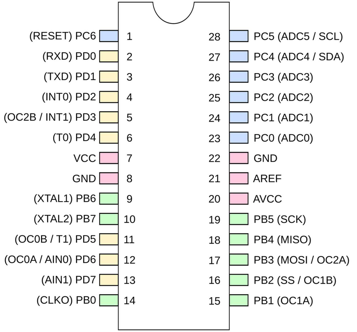
Figure 1-1. AVR pins and their functions
Each pin on the AVR has a name, and you’ll see later on how you can refer to them all in code. So if I hook an LED up to pin number 14, I can then write a high voltage or low voltage out to that pin by referring to it as PB0. Most of the pins on the AVR also have secondary functions, and these are listed as mnemonics in parentheses. For instance, RXD and TXD are the receive and transmit functions for the serial port functionality and live on pins PD0 and PD1, respectively. By the end of this book, you’ll know what all of the terms in parentheses mean and will have played around with almost all of their special functionalities.
Internally, and somewhat according to function, the pins are arranged into banks of eight pins. I’ve color-coded the pins according to their banks. (I wish they were all located in consecutive blocks, but there’s nothing you can do about that without building your own circuit board.) Because each bank, for instance, “bank B,” has a maximum of eight pins in it, you can refer to them by an eight-bit binary number to turn on or off their voltage source. You’ll see a lot more of this in Chapter 3 and onward.
Rounding out the miles-high overview here, you can access all of these pins and their various functions from within your code by reading from and writing to special I/O registers in the chip, which your code will be able to access as if they were any other variable. For instance, a register PINB contains the input pin state of all of the pins in Bank B. You’ll read it in with code like:
thePins = PINB;
and then you can do whatever you’d like with the variable thePins that has captured the current pin states. Similarly, a register “variable” PORTB can be assigned to as if it were a normal variable:
PORTB = 42;
with the side effect that certain pins in bank B will get set to the logic high voltage level, and others will get set to 0 V. And changing the voltage level on these pins turns on and off motors or LEDs, plays sounds on speakers, or encodes and transmits numerical data.
All of the above is actually worth a couple of chapters, so don’t worry if it’s not crystal clear yet. The point is that code you write has physical side effects on the chip: directly controlling or reading the voltage levels on the pins. And with that, it turns out, you can do anything. The rest is just the details.
DATASHEETS
Newcomers to AVR microcontrollers are often surprised when they eventually figure out how useful the datasheets are. They answer just about every question you’ve got about how the chips work. For instance, I adapted Figure 1-1 from page 2 of the datasheet.
But the datasheets are imposing—the ATmega 48/88/168 series is 450 pages long! And the datasheets don’t seem helpful at first—the datasheet tells you everything about how the chip works, but almost nothing about how you should work with the chip. Some sections of the datasheets are nearly impenetrable unless you already know the basics of what’s going on inside the chip already.
The trick is to approach the datasheet like a reference book rather than a novel. If you’re learning a new foreign language, you don’t start by opening up a dictionary to page one and reading onward. A dictionary is most useful when you already have a basic idea of how the language works, but you’ve just forgotten how to say “lemur” in Portuguese.
And so it is here. I’ll refer to the datasheets throughout this book as you learn to use new functions. One of the important skills you’ll learn working through this book is how to read the datasheets.
So take a moment right now to go fetch the full datasheet for the chip we’re going to be using, the ATmega168. Read the first page and then stop for now. If your PDF reader supports indexing, enable the index sidepane and maybe give it a look-through. But don’t dive in head first just yet—we’ll be dipping into the datasheets frequently throughout this book, and you’ll get a feel for them as we work along.
So without further ado, here is a whirlwind tour of the hardware that’s built into an AVR microcontroller and what it’s good for.
The Core: Processor, Memory, and I/O
CPU
The central processing unit (CPU) of the AVR is basically very similar to that in your laptop or desktop computer. It is a bit of electronic circuitry that has a bunch of predefined logical and mathematical operations built in, and knows where to find a list of these operations to follow (your program) and where to get the data it needs to execute them.
Memory
AVR microcontrollers have no fewer than three different memory types, each with different uses.
1. Flash. Your compiled program code gets stored in nonvolatile flash memory. It doesn’t disappear when the chip loses power. In fact, it’s guaranteed to only lose 1 bit per million after 100 years at room temperature. We’ll discuss uploading your code to flash memory in Chapter 2.
2. RAM. Naturally, there is some memory for storing temporary variables while doing calculations and so forth.
3. EEPROM. EEPROM is slow to write to, and there’s not much of it, but like flash program memory, it stays around when the power goes out. We’ll talk about using EEPROM in Chapter 19.
Clocks
All computers need a sense of time. In the AVR chips, there are multiple clocks that are all derived from the same common timebase but often divided down through their own individual prescalers. We’ll use the internal RC oscillator as the master clock source. It runs at around 8 MHz. The CPU clock is then divided down from the master clock, and runs at 1 MHz by default, but sometimes when we need the extra speed, we’ll bump it up to the full 8 MHz.
Following the CPU clock come all the other peripheral clocks, most of which have their own prescalers relative to the CPU. There are clocks for the I/O subsystem, the analog-to-digital converter, RAM, and Flash and EEPROM. When you’re using any of the peripheral subsystems, remember the clock prescalers—you’ll often have to set their values. These multiple clocks derived from the same source keep everything running on schedule together.
Outputs
Almost all of the pins on the AVR chips can be configured so that they’re usable as digital outputs, meaning that the pin can be commanded in software to output either the supply voltage level or the ground voltage level. (Call these voltage levels VCC and GND, or ground.) Any way you slice it, digital output is the heart and soul of microcontroller programming. It’s how you “speak” to the outside world. We’ll go into digital output in great depth in Chapter 3.
“ANALOG” OUTPUTS
If you’ve used the Arduino platform, you might think of some of the outputs as “analog” outputs, but there aren’t really any truly analog outputs on the AVR series micros. What the Arduino code is doing behind the scenes is switching the pin state very rapidly between the high and low voltages so that the average voltage is somewhere in the middle. This is called pulse-width modulation, and we’ll cover it in detail in Chapter 10.
Inputs
Just as almost all the pins can be set up as outputs, they can also be configured as digital inputs, where they detect if the voltage applied to the pin externally is high or low. Specifically, if the voltage on the pin is greater than half of the supply voltage, the chip sets a bit in an internal variable to one. If the voltage is lower than the threshold, that same bit reads as zero.
Hook up a button to the supply voltage on one side and to ground through a resistor on the other. Reading the voltage off of the high side, you’ve now got a digital signal that’s high (or one) when the button is not pressed, and zero volts when the button is pressed. If you now connect this to an AVR pin that’s set up for input, your code can read whether the button is being pressed or not by testing if the voltage on the pin is closer to zero volts or VCC.
You’ll see a lot more about digital inputs and pushbuttons in Chapter 6.
So far, I’ve described a tiny computer that can run programs that read and write values out to pins in the form of digital logic voltages. That’s essentially all there is to it—with this framework you can implement nearly anything. And a broad range of very useful microcontroller applications can be built with just this ability.
The rest of the microcontroller’s hardware is dedicated to making your life as a programmer easier and to making many common tasks more reliable.
Peripherals: Making Your Life Easier
Serial communications
One of my favorite uses of microcontrollers is as the connector between a real computer and interesting hardware. Say you want to strap accelerometers to your body, dance around like it’s 1999, and pass this data off to your laptop, which renders a 3D figure of you in real time. The job of the microcontroller here is simple: talk to the accelerometers, do a little math and light up some LEDs perhaps, and send all of the data to your laptop. But what language do the accelerometers speak? How about your desktop?
The AVR has three serial communications peripherals built in. Plain-vanilla USART serial in Chapter 5 is useful for communicating with your desktop computer, radio modems, and GPS units. SPI (Chapter 16) is good for ultra-fast communication over very short distances with peripherals like memories, ADCs, and DACs. I2C (Chapter 17) is like a small network, allowing you to connect up to 127 different sensors to the same couple of wires. Devices that move around a moderate amount of data tend to use I2C. That’s a good choice for the network of accelerometers.
Because each of these serial hardware peripherals is separate inside the AVR, you can use each of these at the same time. Your AVR can communicate with virtually anything.
Analog to digital converter
A number of the useful sensors that you’d like to connect to your projects don’t speak the microcontroller’s native digital language; rather, they speak in terms of continuous analog voltages. To read in these values and manipulate them like you’ll manipulate any other digital data, you’ll need to run them through an analog to digital converter (ADC). In Chapter 7, you’ll make good use of the ADCs in building a light sensor and variable-threshold night light. In Chapter 12 I’ll go over some more advanced ADC applications, including building a vibration sensor that can detect footsteps indoors, and introduce you to oversampling and exponential smoothing—two techniques that can get you more precision or remove noise from your ADC readings.
Interrupts
You’d like your program to be able to react to the outside world: you press a button, you’d like something to happen. Heck, that’s half of the fun of writing code for a microcontroller. Or maybe you’d like your program to do something every so often, as the previous examples using timers/counters make clear. Hardware-level interrupts are just the ticket.
An interrupt service routine is a software function that you can write that automatically executes whenever an interrupt condition is met. They’re called interrupt routines because the processor stops whatever it was doing in the main flow of your program and runs the appropriate function. After it’s done with the interrupt routine, the processor picks up your program’s normal operation where it left off.
There are many ways to trigger interrupts in the AVR microcontroller. These interrupt conditions include a press on the reset button, a changing input value, an internal clock tick, a counter value being reached, data coming in on the serial port, an analog-to-digital conversion finishing, or many others. The point here is that there are loads of interrupt conditions and they each can trigger their own function calls.
Interrupts and interrupt service routines are fundamental to advanced AVR programming, and along with timers form most of the content of Part II.
Timers/counters
The AVR microprocessors have built-in hardware counters. The counters are basically what they sound like—they keep a running count of how many times a pin or internal source has changed its voltage level.
The simplest counter application is hooking up the internal counter to a button. Now whenever your program wants, you can tell how many times that button’s been pushed by just reading the counter’s register. (You can write to the counter as well, so you can reset it to zero at the beginning of any day, for instance.)
Counters really come into their own when paired up with clocks, and this is why they’re often referred to as timer/counters. With a clock and a timer, you can measure either how long some event takes, or the event’s frequency. You’ll even be able to output to certain AVR pins (OCRxn in the pinout diagram) and fire off special subroutines periodically. The timer/counter peripherals are tremendously configurable and turn out to provide more functionality than you would have thought. Which is great, because there are three of them.
You’ll see a lot more applications of the timer/counters throughout Part II.
THE AVR FAMILY OF MICROCONTROLLERS
Although we’ve settled on the AVR ATmega168 for the purposes of this book, you might want to tailor the chip to your specific project later on. There are many, many AVR microcontroller chips to choose from, each with different capabilities at different price points. Finding the one that’s right for your project can be intimidating. You can spend hours choosing the chip that has the peripherals you need and enough memory to fit your code, and then locating the least expensive part.
If you’re just working on a prototype and you want to get something working as fast as you can, you probably shouldn’t worry about spending an extra 50 cents per chip. You’re better served by having a few chip types on hand, and just picking the best fit from what you’ve got. Here’s my current working set:
Small: ATtiny45
The x5 series chips are small and cheap, great for when you only need five I/O pins. They also have a high-speed peripheral clock that can run up to 66 MHz, which makes them uniquely great for PWM applications, and for use in conjunction with the V-USB firmware USB library to build your own USB peripheral devices.
The only differences between the 25, 45, and 85 are the amount of program memory (2 kB, 4 kB, and 8 kB) and the price, so there’s a trade-off. For me, 4 kB of memory is the sweet spot.
ATtiny45s cost around $1 singly or $0.65 in bulk as of this writing.
Medium: ATtiny 44
An attractive step up from the 45 when you don’t need the high-speed PWM of the Tiny45. For just a few cents more, you get 11 I/O pins and a 16-bit timer. Even though they’re relatively new on the market, these chips are becoming my go-to for small projects as well.
ATtiny44s cost around $1.15 singly or $0.75 in bulk as of this writing.
Large: ATmega xx8 Family
Now we’re talking—the Mega xx8 chips are deluxe! If you’re going to focus on one chip series, this is the one. At this level, you get 20 I/O pins, hardware USART, three timers, and a whopping 16 kB of program memory. There’s a reason the wildly popular Arduino platform is based on Mega 168s and 328s.
And because the Mega 48, 88, 168, and 328 all have the same features outside of program memory, it’s often possible to just swap out a chip and save a few dollars on a project. The Mega48s give you the same functionality for half the price of the mega168s that we’re using when you don’t need the extra memory.
ATmega168s cost around $2.25 singly or $1.50 in bulk as of this writing.
Now, there are lots of other options besides the chip family and member. Searching for “mega168” at an electronics house yields over 50 results: ATmega168PA-10PU, ATmega168-AU, and so on.
The letters after the part number (168P or 168PA or 168A) represent different versions of the chips. The “V” variants are guaranteed to run at lower voltages, but are only guaranteed to run at reduced speed. The “P” and “V” series are an older design. The “A” and “PA” variants represent newer designs that use less power (P) or run full-range across speed and voltages (A) or both.
The extensions represent the package size and will often be described in words. PU (PDIP) is the largest, and is the through-hole standard part. AU (TQFP) is 1.0 mm spacing surface-mount and is entirely doable if you’re comfortable with SMT. The MU packages are very difficult to solder by hand.
The number in the extension is a speed grade, and chips that end in 10, for instance, are only guaranteed to run up to 10 MHz. When there is no numeric extension (as with the modern chips), the chip runs at full rated speed, which is usually 20 MHz at 5 V.
So which variant, in which package? P, A, or PA are safe bets, and I’m basically indifferent among them. Go A or PA if you’re stuck. For packages, pick PU (PDIP) if you’ve got little or no experience soldering, and AU (TQFP) if you enjoy surface-mount work.
All materials on the site are licensed Creative Commons Attribution-Sharealike 3.0 Unported CC BY-SA 3.0 & GNU Free Documentation License (GFDL)
If you are the copyright holder of any material contained on our site and intend to remove it, please contact our site administrator for approval.
© 2016-2026 All site design rights belong to S.Y.A.