Make: AVR Programming (2014)
Part I. The Basics
Chapter 2. Programming AVRs
Hello World!
In this chapter, you’ll get set up with everything you need for coding, compiling, and flashing your programs into the bare silicon of the AVR chips that are sitting on your desk right now. To do so, you’re going to need some hardware (a flash programmer) and some software (a code editor, C compiler, and the program that’ll communicate with the hardware flash programmer). Finally, you’ll need to hook up some wires from the programmer to the AVR chip and get set up with a power supply.
In this process, there are a lot of different approaches that will get you to the top of the same mountain. Ultimately, the different approaches are all basically the same at some abstract level, but we’ll step through some details of a few of the most popular options to make things clearer.
On the hardware side, most of the flash programmers work about the same, and the differences there won’t amount to much more than a few tweaks to a file that you’ll use over and over again. Flash programmers, after all, are just USB devices that send bytes of your code across to the AVR chip. On the software side, different development packages will have different looks and feels, but in the end it all comes down to editing code, compiling it, and then sending it off to the hardware programmer.
WHAT YOU NEED
For this chapter, you’ll just need the basic kit as described in The Basic Kit. For convenience, I’ve summarized that here:
§ A solderless breadboard.
§ Wire jumpers to plug in to the breadboard.
§ An ISP programmer.
§ An ATmega168, 168A, 168P, or 168PA.
§ An LED (any color) and an appropriately sized resistor: 200–500 ohms.
§ A source of 5 V DC power (if not supplied by your ISP); a 4xAA battery pack is nice anyway.
§ One 100 nF (0.1 μF) capacitor to smooth out the AVR’s power supply.
Programming the AVR
The words “program,” “programmer,” and “programming” are overloaded in the microcontroller world. We (as programmers) write programs, compile them, and then use a flash programmer to program the AVRs, which then runs our program. Pshwew! Let’s step through the actual procedure and see what’s actually going on.
Toolchain
It’s a long and winding road from the code you type into your editor to a chip on your desk that turns a light on and off. Getting from typed letters on a computer screen to a working piece of electronic machinery requires a chain of tools called, predictably, a toolchain!
Toolchain overview
1. Write your source code in an editor.
2. Turn your source code into machine code with a compiler (and associated software tools).
3. Using uploader software on your big computer and a hardware flash programmer, send the machine code to your target AVR chip, which stores the instructions in its nonvolatile flash memory.
4. As soon as the flash programmer is done, the AVR chip resets and starts running your code.
Figure 2-1 sketches out the main steps in AVR firmware development along with which tools you’ll use for each step.
The first step in your toolchain is going to be a text editor, or whatever you’re most comfortable writing code in. For the Linux folks out there, gedit is quite nice. On Windows platforms, you’ll probably find the editor that comes with WinAVR, Programmer’s Notepad, will work pretty well, but I prefer the freeware Notepad++. Many Mac coders swear by TextMate. If you’ve already got a favorite code editor, by all means feel free to use it. Nice features to look for include syntax highlighting, automatic formatting and indenting, parenthesis matching, and maybe even code folding. (Put your copy of Microsoft Word away—that’s not what we’re looking for here.)
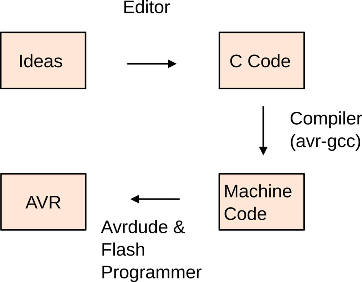
Figure 2-1. AVR programming toolchain
ASIDE ON WINDOWS EDITORS
Both Programmer’s Notepad and Notepad++ let you compile and flash code directly from the editor with a single button push, which is handy because the Windows command line isn’t very familiar to most folks.
In Programmer’s Notepad, there are options for calling your makefile in the Tools pull-down menu, and you’ll see the results of your compilation and uploading in the “Output” panel at the bottom of the screen.
In Notepad++, use the Run pull-down menu, and type in cmd /K cd /d $(CURRENT_DIRECTORY) && make flash to open up a command window in the current directory, compile your code, and flash it to the AVR. The /K leaves the window open after it’s done, so you can read any errors in compiling or uploading that may have occurred. You can also run it with /C if you don’t want to see the output.
With both of these editors, you can also bind these actions to a key combination so that compiling and uploading your code is as easy as it would be in an IDE. Pretty slick.
Of course, if you want to get a whole IDE, I won’t stop you, but it’s not at all necessary. For Windows, Atmel Studio is comprehensive and centered on the task at hand. If you use Eclipse, there are AVR plug-ins as well. If you don’t know what any of this means, skip this paragraph: learning a new IDE is itself a day’s work, and too much detail to get into here. I don’t recommend it when you’re just starting out.
Anyway, once you can write and edit code, you need to compile it for the AVR, turning your human-readable C code into machine code for the AVR. The compiler we’re using, avr-gcc, is the AVR-specific version of the popular open source compiler GCC. (In fact, I would argue that the support from Atmel for avr-gcc and an open source toolchain is the main reason for the chip’s amazing success in the hacker community.)
In addition to the compiler, you’ll need a few more software tools from the avr-gcc suite to go from source code to machine code that’s ready for uploading. A script called a makefile is commonly used to automate all of the repetitive, intermediate bits of the process. See Make and Makefiles if you want to learn a little more about what’s going on with the makefiles, but don’t sweat it if it’s too much info—you can do everything you need to by simply editing a few lines, and I’ll walk you through that.
Once you’ve compiled your C code into machine code in the right format, it’s time to send the machine code over to the chip and write it into nonvolatile flash memory. The flash programmer is a piece of hardware that sits in between your computer and the target AVR microcontroller. The AVR microcontrollers, when put into programming mode, listen over their serial peripheral interface (SPI) bus for incoming data to flash into program memory. The flash programmer’s job is to relay the compiled machine code to the target AVR over the SPI bus. There are tons of flash programmers available, and I’ve listed some of my favorites in Flash Programmers I Have Known and Loved.
A lot of you will have an Arduino sitting around. If so, it turns out to be fantastically easy to turn that Arduino (temporarily) into an AVR programmer. I’ll walk you through the steps to do so, and how to wire it up, in AVR and the Arduino. So if you don’t have a dedicated hardware SPI programmer just yet, I’ll get you up and running with an Arduino.
Now, stepping back to your main computer, you’ll need to run software that feeds the compiled machine code to the flash programmer. Far and away the most popular software uploader is AVRDUDE, which is available for all platforms and supports a wide variety of programmers. How wide? So wide that almost any way that you can think of communicating in SPI with the target AVR will work with AVRDUDE, from a few wires hooked up to your parallel port to dedicated USB programmers with their own AVR microcontroller brains.
TO RECAP:
1. Plan. This stage just requires your brain, some paper and a pencil, and maybe the AVR datasheet so you can figure out which parts the onboard hardware can help you with. Think through what you need the chip to do, and break it up into functions for each logical step.
2. Code. Write your program using whatever text/code editor makes you happy. Here you’re just translating the ideas behind the functions into valid C code.
3. Compile. Turn your C code into AVR machine code with avr-gcc and its associated tools, most likely run from a makefile. Type make and read through the compiler errors, then go back and fix them.
4. Flash. Hook up a flash programmer to your target AVR and then run AVRDUDE to send the machine code through the programmer to the AVR chip, which saves it in flash memory. (Or just type make flash and watch it go.) Did flashing work?
5. Test. Once you’ve uploaded your code to the AVR, does it do what you want it to? Test it under many differing conditions before you’re sure. You’ll find all sorts of interesting real-world situations where your sensors aren’t reporting data as you thought they would. Now’s a good time to find that out, so you can recode around it.
6. Debug. There are many tricks for figuring out what’s going wrong with your code—from lighting up status LEDs, to transferring variable data information over the serial line to your desktop computer, to stepping through the code with a debugger.
PROGRAMMING THE AVR—WHAT’S REALLY GOING ON?
AVR microcontrollers are able to write into their own flash program memory space. All of the ATmega series microcontrollers are set up so that when you reset them, they start listening for data on the SPI lines, and with the right instructions can program themselves.
A flash programmer works by grounding the RESET line, which halts the CPU and signals the AVR to start listening on the SPI bus. The programmer then transmits programming instructions over the SPI bus. After each instruction or section of code, the AVR writes the received data to flash memory. Some of the tiny AVR chips flash the data to program memory after every few bytes, which can be slow. Larger and newer chips store the incoming data in a temporary page memory and then write it all at once, which is much, much faster.
After the programming is complete, you can read the data back out of the AVR’s flash program memory to verify again that its correct. The -v flag for AVRDUDE does this for you.
For a deep read on programming the AVR chips, for instance, if you want to implement your own flash programmer or write your own bootloader once you’re done working through this book, see Atmel’s “Application Note AVR910”.
The Software Toolchain
The main feature of the style of software development that we’ll use in this book is cross-platform compatibility. That is, if you’re used to the whole workflow of writing code and compiling it on a Mac, you’ll have the same tools available for you on Windows or Linux, and you can be sure that you’ll always know what you’re doing wherever you go. After all, the target of all our work here is a little 8-bit microcontroller that doesn’t know anything about what operating system you use.
Linux Setup
Setting up the toolchain for programming AVRs on Linux is tremendously simple. If you’re using a Debian-based distribution (like Ubuntu or Mint or, heck, Debian) you can simply type (all on one line):
sudo aptitude install avrdude avrdude-doc binutils-avr avr-libc gcc-avr gdb-avr
Red Hat and Fedora users type:
sudo yum install avrdude avr-gcc avr-binutils avr-libc avr-gdb
All other Linux users will find that it’s easy enough to find source packages for all of the above. See http://www.nongnu.org/avr-libc/user-manual/install_tools.html or http://avr-eclipse.sourceforge.net/wiki/index.php/The_AVR_GCC_Toolchain for details.
Windows Setup
Windows users have two options for the software toolchain, one based on the (huge) Atmel Studio and one based on WinAVR. Weighing in at 1/20 the file size and 9/10 of the functionality, I’d choose WinAVR. The current download link is from SourceForge and is a little bit old, though I’ve had no troubles with it. It’s very well tested and fully debugged.
A hackerspace in Australia has taken up the task of making a more-recent WinAVR clone, and you can try your luck with http://www.makehackvoid.com/project/mhvavrtools if something in WinAVR doesn’t work for you. (That said, I’ve never had any problems with WinAVR.)
During the installation, WinAVR will offer to change your PATH variable so that all of the binary files (importantly make, avrdude, and avr-gcc) are available without typing the full pathnames in. Be sure that you allow this.
Mac Setup
AVR CrossPack is the way to go for Mac. It includes all the compile tools, AVRDUDE, and more. It’s kept up to date and should just work.
Arduino Setup
As a fourth option, the Arduino IDE is available for all three OS platforms. Heck, most of you will have it installed already. If you’ve got Arduino up and running, there are some modifications you can make to turn your Arduino IDE into a working generic AVR C-language environment. See AVR and the Arduino and, in particular, Writing C in the Arduino IDE for details.
If you’d like to use your Arduino as a hardware flash programmer, but don’t plan to use the Arduino IDE, you can do that too. In addition to the Arduino install, install the software toolchain for your OS.
Make and Makefiles
The C programming language lets you split up one big program or task into a bunch of individual functions, and lets you keep collections of functions together in their own files for easier maintenance and portability. That way, if you want to frequently reuse some serial-port input/output functions, for instance, all you have to do is include the serial library code files (by name) in your main code, and then tell the compiler where to find these files. Separating your code into functionally different files is good software design, but it means that you need to remember all of the dependencies among the different files in your codebase and type out potentially many filenames each time you compile.
Keeping track of all of these dependencies manually can quickly become unreasonable, and it was only a few years after C was invented that the make utility was designed to help. Instead of compiling your files together manually, a file called a makefile contains a bunch of dependency rules and instructions for processing them, and then you just run the make command and everything compiles. (That’s the idea, anyway.)
So, for instance, you can explicitly compile all of your source files together like this:
gcc main.c another_file.c serialLibrary.c -o main
which makes an executable file, main, from all of the listed .c files. Or, you can write a makefile that maps out these dependencies:
main: main.c another_file.c serialLibrary.c
and then simply type make main or even simpler, make. The make program knows that names on the left side of the “:” are targets, and on the right, their dependencies. If you need to run special commands to make the targets from their dependencies, these commands are listed on the next line, indented with a tab.
Dependencies can, in turn, have other dependencies, and make will keep digging deeper until it can resolve them. Things get complicated with makefiles when you add in variables and wildcards that match any filenames. You can start to write generic rules that compile any .c files together, for example, and then you only have to change the variable definitions when you move a makefile from project to project.
I’m including a preconfigured makefile for each project in this book’s code repository. You may be able to use them as is, but we also might have different AVR programmers and different serial ports, so you’ll eventually want to at least modify some of the definitions. We’ll step through configuring the makefile to fit your setup in Configuring Your Makefile.
Now that you’ve got the software set up, all you need is to connect up a flash programmer to the chip and test it out. Here, you’ll have two choices. If you don’t have a dedicated AVR flash programmer yet, but you have an Arduino lying around, the next chapter is for you. If you’d like to buy a dedicated AVR flash programmer, I have some advice in Other Hardware Programmers. Otherwise, if you’ve already got a flash programmer, you may proceed straight to Getting Started: Blinking LEDs and get started.
AVR and the Arduino
A bunch of you are going to be used to the Arduino programming environment. That’s great! In this book, I’ll be teaching you all of the powerful nitty-gritty that Arduino hides from you in the name of easy accessibility. But that doesn’t mean that there’s any reason to let your Arduino gather dust—in fact, the Arduino platform can be a great generic AVR playground, once you know how to (ab)use it.
Arduino Pros
One very real advantage of the Arduino hardware setup is that the chip comes pre-flashed with a bootloader, which is code that enables the chip to communicate with your computer over the serial line in order to flash program itself. This means that you can do away with the requirement for an external bit of hardware to flash the chip—there’s a tiny bit of bootloader code already running in your Arduino that’ll flash the chip for you!
The second highlight of the Arduino package is that it comes with a built-in USB-to-serial converter, so you don’t have to buy a separate one just yet. I personally get a lot of mileage out of my USB-Serial cable, and you will too if you want to play around with freestanding microcontrollers, GPS units, old terminals, hacked WiFi routers, and other devices. If you’re going to get serious about embedded electronics hacking, you’re going to want a standalone USB-Serial adapter eventually, but it’s sweet that the Arduino lets you get away without buying one for the time being.
And finally, although it’s not such a big deal, the Arduino is powered by your computer’s USB power supply. This is handy if you’re developing code on your laptop in a park or on a plane. You don’t need to find a wall plug for your power adapter or remember to bring batteries along with you—all you need for flashing, communications, and power is a USB cable.
Arduino Cons
As good as the Arduino hardware is as a generic AVR development platform, it’s not perfect. For use with this book and our examples, there are a number of disadvantages to using an Arduino instead of just plugging an AVR chip into a breadboard.
Probably the first among these disadvantages is the lack of the breadboard itself. Shields are great for finished products, but when I’m building up a hardware section for the first time, it’s nice to test it out on something more flexible like a breadboard. I find that the more complicated my external circuitry gets, the less suitable working on the Arduino becomes. The Arduino is great for plugging a few LEDs or a couple of sensors into. But when things get interesting, I end up having to jumper the Arduino into the breadboard with 10 or more wires like some demented spider, and then my dog knocks something loose, and it takes a long while to debug the problem, and that’s when I wish I’d just stuck a chip into the breadboard in the first place. (True story.)
Another downside to using an Arduino as an AVR development platform is that a few ports and pins are already irreversibly wired up and unavailable for use. For instance, when we make an eight-LED POV toy in Chapter 3, you’ll discover that two of the pins that I’d like to use for LEDs are already hard-wired up to the crystal oscillator. It’s a design trade-off—because it’s clocked with a 16 MHz crystal oscillator, the Arduino is able to run twice as fast as an AVR using only its internal timebase.
But because the Arduino ties up two of the pins in PORTB, you’ll only be able to make a six-LED cylon without having to do some elaborate coding as a workaround. If you want to display a byte’s worth of data on PORTB, you’ll be missing the most significant two bits.
Arduino boards aren’t cheap either; just compare an Arduino Uno with the AVR ATmega328p chip that powers it. You can buy 8 or 10 AVRs (or 20 ATtiny 45s) for the price of one Arduino. This is because the Arduino has extra hardware—power regulation, USB-to-serial, and other circuitry onboard—which makes them overqualified for many trivial applications. This also makes an Arduino too expensive to commit to a one-off quickie project, and that’s a real shame because nothing in the world is better than giving your young niece a goofy microcontroller-based toy that you made for around $5 in parts. (That said, if you can prototype the toy faster because everything’s wired up for you on the Arduino, go for it. A goal of this book is that you’ll be able to move fluently between the “Real AVR” world and Arduino.)
More trivially, it’s a minor pain to be always going back and forth between the pin names in the datasheet (”PB5" and similar) and the Arduino’s pin names (“Digital 13” and so on). Figure 2-2, which is similar to the sweet ASCII art in arduino-1.0.4/hardware/arduino/variants/standard/pins_arduino.h, should help.
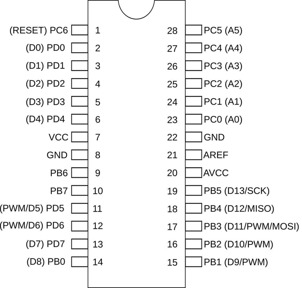
Figure 2-2. AVR pinout and Arduino labels
So if you’re working along with code from this book, and you need an LED connected to pin PB0, for instance, you’ll want to hook up the same LED to your Arduino’s Digital 8 pin. (And see how the Arduino doesn’t use pins PB6 and PB7?)
Finally, the Arduino bootloader needs to use the watchdog timer, which is a timer that effectively reboots your AVR chip automatically if your code gets hung up and doesn’t check in every once in a while. We won’t even use the watchdog timer in this book, but if you need to make a very robust design, it’s a nice trick to have up your sleeve.
But don’t let these gripes overshadow the main point—an Arduino can also be turned into a fine C-language AVR-programming platform. And besides, if you’ve got one sitting on your desk, you might as well use it.
The Arduino: Hardware or Software? Both!
In the next two sections, I’ll show you how to use the Arduino—both the software IDE and the physical hardware—as an AVR learning platform. The first section covers programming the AVR chip that’s inside the Arduino (as you normally would) but using standard C instead of the strange Arduino dialect. This way, if you’ve already got an Arduino in hand, but AVR chips and a breadboard in the mail, you can get started working through this book by programming the Arduino board directly.
The second section treats the case where you’ve already got your AVR chip on a breadboard, and you want to use your Arduino as a hardware flash programmer to transfer the code to the target AVR. Following some simple steps, you can (temporarily and reversibly) use the Arduino as a hardware programmer to flash your code into the bare AVR. And then you can decide to continue using the Arduino IDE to compile and send your code, or you can use any other code editor and the standard AVR development toolchain. The choice is yours.
CHOICES, CHOICES!
From my perspective as an experienced coder and microcontroller user, I like to use my own favorite development tools rather than the Arduino IDE. It’s also a lot easier and faster to prototype circuits with a bare AVR on a breadboard than using the Arduino hardware.
However, using the Arduino as a hardware programmer is tremendously comfortable, even if you’re used to more advanced tools. With just six wires between the Arduino and your breadboard, you’ve got a source of power and a flash programmer that’s just as good as any other.
If you’re willing to learn a bit more about the non-Arduino toolchain—programming in standard C, using makefiles, and all that—you’ll be learning some transferrable skills that will work on other hardware platforms and microprocessor architectures. And then if you eventually swap out the Arduino-as-programmer for dedicated hardware, you won’t even notice.
The Arduino Is an AVR
If you’re shy about leaving the comfortable Arduino IDE, you don’t have to. With a few tweaks, the Arduino compiler can be fooled into compiling standard C code, which you can then flash directly to the AVR that lives inside the Arduino hardware. So if you’re coming from the Arduino world and you’d like to get started with this book right away—you can!
The reason that this all works is that the Arduino environment is really just a thin GUI layer that ties together the standard AVR toolchain—GCC as a compiler and AVRDUDE to talk to the flash programmer. In short, you can start off with the full Arduino IDE and slowly migrate over to doing everything manually, or vice versa.
Writing C in the Arduino IDE
If you’re used to the Arduino IDE and don’t want to try out another code editor, for instance, the following steps will enable you to compile and flash valid C code with minimal changes to your old workflow. Follow these steps whether you’re programming for the Arduino’s onboard AVR chip or for an external AVR target on a breadboard—anytime you want to write straight AVR C code within the Arduino environment.
To get running in C with the Arduino IDE, there are two things that you’ll have to do only once, before you even start the IDE:
§ Copy over whatever libraries you need to go with your code. In writing the code for this book, I ended up using a few bits of common code in almost every project. It makes more sense to put all of these common files in one place. To use this “library” of common code, create a directory in your libraries folder (~/sketchbook/libraries on Linux and Documents/Arduino/libraries on Windows) and copy your common code here. Now you’ll be able to use it within any other program by simply by importing the library. So copy theAVR-Programming-Library folder out of the code directory and into your sketches library right now.
§ If you’re going to be coding for an ATmega 328P, either in an Arduino (the Uno, for instance) or as a standalone chip, fix up your portpins.h file. See portpins.h and the Arduino IDE. If you’re going to use an ATmega168 or other chips, you don’t have to follow this step, but it won’t hurt.
Now that your Arduino IDE is set up, it’s time to get coding. In this example, I’ll assume that you’d like to copy some code out of one of the book’s projects, but the same basic steps apply for when you’re writing it yourself:
1. Start the Arduino IDE.
2. Import the header files into the project using the Sketch → Import Library pulldown, where you should find the AVR-Programming-Library folder at the bottom of the list. Notice that the Arduino IDE adds include lines for each header file in your directory.
3. Save this (mostly blank) sketch with a descriptive name. This will create a directory for you to put your code in.
4. Outside of Arduino, copy the C code file that you’d like to use into the sketches directory. If you press Open and reopen the sketch, you should see this newly added code in a new tab.
5. Alternatively, you can write new C code in the sketch by opening up a new tab (Ctrl-Shift-N, or from the arrow menu in the top-right corner) and then entering the code directly.
6. To make sure that all works, click on the Verify button. If it does, then you’re ready to flash the code.
PORTPINS.H AND THE ARDUINO IDE
The code compiler that the Arduino IDE uses is the same GCC as you’d use if you were compiling manually. As such, it doesn’t care if you pass it code written in C for the AVR, or in C++, using the Arduino libraries. Along the way, though, I found a gotcha.
For whatever reason, the portpins.h include file that comes with Arduino 1.0.4 and previous is old (2006!) and doesn’t conform to modern usage. The end result is that standard pin-name macros like PB1 don’t end up getting defined for the mega328 chip, while the old-style PORTB1 macros are.
If you want to compile for an ATmega 328P chip (as is found on the Arduino Uno, for instance), you’ll want to replace the portpins.h file with a more recent version. On my system, I found the file in arduino-1.0.4/hardware/tools/avr/lib/avr/include/avr/portpins.h. Replace this file with the version that I’ve included with the book’s code library, and you should be able to just write C.
If you see errors like PB1 undeclared (first use in this function), that’s the portpins.h bug.
Flashing the Arduino as target
This is super simple from within the Arduino IDE, because programming the Arduino is what it’s meant to do. The only difference here is that you’re writing your code in real, portable C rather than Arduinoese:
1. Verify that your board type is selected in Tools → Board.
2. Make sure you’ve included your library using Sketch → Import Libraries, and that the #include lines appear in the first sketch tab.
3. Click Upload (or type Ctrl-U) to flash your code into the AVR inside the Arduino hardware. Easy.
The Arduino Is an AVR Programmer
Or at least it can be. In this section, you’re not going to be writing your code into the Arduino as a target, but rather using it as the middleman. You’ve got an AVR chip that you’ve stuck into a breadboard, and you’re going to use the Arduino as the hardware programmer, thanks to example code that converts the Arduino into an Arduino In-System Programmer (ISP). You can do this either from within the Arduino software IDE, or you can use an editor and the avr-gcc toolchain independently.
Wiring your Arduino as a flash programmer
The first step toward using your Arduino as a flash programmer is hooking it up to your breadboard. The essential six connections are power, ground, RESET/PC6, SCK/PB5, MISO/PB4, and MOSI/PB3. (You’ll find these pin names in Figure 2-5 on page 2 of the AVR datasheet, or you can also just refer to Figure 2-3.)
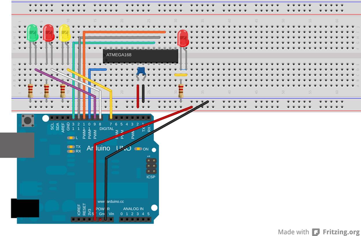
Figure 2-3. Arduino as flash programmer
The single red LED hooked up to pin PB0 on the target AVR is the LED in question if you’re uploading this chapter’s blinkLED code.
The three (optional, colored) LEDs hooked up to the Arduino are status lights. Green will pulse while the ArduinoISP is waiting for input, yellow will light when it’s transferring code to the AVR, and red will light if there’s an error. You can leave these out, but they make everything look so professional, no?
Resistor values for the LEDs aren’t too critical, but something over 200 ohms is a good idea for normal LEDs, which commonly have around a 1.7 V threshold voltage, and are rated for around 20 milliamps: (5 V – 1.7 V) / 220 ohms = 15 milliamps.
Flashing AVR chips using the Arduino as a programmer
Now that the hardware is wired up, let’s use it to program the AVR chip! Following these instruction will turn your Arduino into a flash programmer. (When you want your Arduino back as an Arduino, you can just reprogram it as usual.)
1. Verify that your Arduino board type is set up correctly (Tools → Board → Uno in my case).
2. Flash the example code “ArduinoISP” into the Arduino hardware the usual Arduino way.
3. If you don’t have a sketch ready to upload yet, go back to Writing C in the Arduino IDE and set up blinkLED.c.
4. Select Tools → Programmer → Arduino as ISP to program through the Arduino hardware instead of programming the Arduino itself.
5. Select Tools → Board → Arduino Pro Mini (8 MHz) w/ ATmega168, because we’re targeting an ATmega168 running at 8 MHz. (Nobody will know it’s not inside an Arduino Pro.)
6. Shift-click on the Upload button (Shift-Ctrl-U) to flash your code into the AVR target. If you’re too accustomed to just clicking the Upload button and forget to press Shift here, you’ll get an error like avrdude: stk500_disable(): protocol error, expect=0x14, resp=0x10.
7. If you want to see what’s going on in the background, click File → Preferences → Show verbose output.
8. Otherwise, sit back and watch your AVR target get programmed. Does it blink? Sweet!
Using Arduino as hardware programmer without the Arduino IDE
Because it’s possible to use your Arduino as a flash programmer from within the Arduino IDE, you’re probably wondering if it’s possible to flash arbitrary AVR chips without using the Arduino IDE as well. Of course it is!
First, make sure that your Arduino is wired up as in Figure 2-3 and that you’ve uploaded the ArduinoISP sketch to the Arduino. Once you’ve done that, you won’t need to touch the Arduino IDE again if you don’t want to.
Open up the blinkLED directory from the software that accompanies this book. Because you’re using makefiles to configure and compile your code, you’re going to need to edit Makefile by hand so that it knows how to use the Arduino programmer. In short, you want to use programmer type “avrisp” at 19,200 baud on the correct serial port.
For Linux, try:
PROGRAMMER_TYPE = avrisp
PROGRAMMER_ARGS = -b 19200 -P /dev/ttyACM0
For Windows, try:
PROGRAMMER_TYPE = avrisp
PROGRAMMER_ARGS = -b 19200 -P com5
For Macintosh using the Uno or Mega 2560, try:
PROGRAMMER_TYPE = avrisp
PROGRAMMER_ARGS = -b 19200 -P /dev/tty.usbmodemXXXXXXX
For Macintosh using any other Arduino, try:
PROGRAMMER_TYPE = avrisp
PROGRAMMER_ARGS = -b 19200 -P /dev/tty.usbserialXXXXXXX
You can figure out which port name the Arduino connects to from within the Arduino environment, under Tools → Serial Port. On Windows systems it will be a COM port, and on Linux or OSX systems it will be /dev/tty-something.
Once your makefile is configured for the Arduino-as-programmer, you’re all set to flash the code over to your chip. If you’ve got a terminal window open, and you’re in the blinkLED directory, typing make flash should do it.
Other Hardware Programmers
If you don’t have an Arduino handy, or if you’d like the convenience of a dedicated hardware flash programmer, you’ve got a lot of good choices. If you’ve got the software already set up, a flash programmer is your missing link. (If you already got your firmware flashed by following the previous Arduino instructions, you can skip this section, or read on for curiosity’s sake.)
Flash Programmers I Have Known and Loved
You have a large number of choices for hardware flash programmers. A programmer can be as simple as a couple of wires, but most of them actually use an AVR or other microcontroller to interface between your computer and the AVR that you’d like to program. Here is a shortened list of some of the good choices you have available:
Parallel port
The first programmer I ever used was not really any programmer at all, but instead just a cable with five wires soldered to a parallel port D-sub connector. This works because AVRDUDE knows how to toggle the lines of a parallel port to program your AVR chips directly. Unfortunately this programming method requires a parallel port on your computer, which is a luxury that fewer and fewer of us have. On the other hand, if you’d like to go this route, search the Web for a DAPA (Direct AVR Parallel Access) cable. Many of the schematics will include “safety” resistors—feel free to ignore them unless you’re hooking up your AVR to voltages higher than 15 V. If you’ve got an unused parallel printer cable lying around, you’ve got your first programmer.
Atmel AVRISP mkII
Atmel’s current official USB in-system programmer, the AVRISP mkII is a very nice programmer that’s capable of programming the whole AVR line, including the newest XMega devices. It’s a bit more expensive than other programmers, but it’s rock solid and is quite a bargain all in all.
USBTiny and USBasp
These two USB-based AVR programmers have super simple hardware designs with open source firmware. You can make one yourself, although you will ironically have to find a way to flash the firmware into the AVR in the programmer (an Arduino ISP is perfect for this). You can also find these designs for sale all over—I’ve got a USBasp-based programmer that I bought for $5 online, and it’s just fine. Both of these designs have a jumper that allows you to power your breadboard off of your computer’s USB port, which is handy for most applications in this book.
LadyAda’s USBTinyISP
This is an improved version of the USBTiny, with input and output buffering. I’ve used one of these for a few years. They come in kits, don’t cost too much money, and have very good build instructions and support. Like the USBTiny project that it’s based on, LadyAda’s programmer can power your project off the USB bus. If you’d like an easy kit to solder together that builds a useful tool, this is a good way to go.
A family portrait of some of my programmers can be found in Figure 2-4, from center-top and going clockwise:
1. An Arduino and six wires makes a totally workable flash programmer.
2. USBTinyISP
3. USBasp, from BaiTe in China
4. USBTiny, tiny version from ehajo.de
5. A homemade programming spider, which plugs into a breadboard around the AVR chip and connects up the programming, power, and reset pins the right way every time. If you’re at all handy with a soldering iron and perfboard, you should make one of these.
Getting Started: Blinking LEDs
OK, let’s get down to business and compile, flash, and test our first AVR microcontroller project. This is not the coolest, most interesting project in this book. The point is to verify that all parts of the programming toolchain are working for you before we start to get a little fancy. In order to minimize the possible ways to mess up, we’ll build up the simplest possible project that puts the software toolchain together with the flash programmer, an AVR chip, and the most minimal possbile feedback—a single LED.
To download the code for this project—and for the rest of the book—visit https://github.com/hexagon5un/AVR-Programming and click the “Download ZIP” button. The blinking LED example is in this chapter’s folder.
Please double-check that you’ve installed an appropriate software toolchain for your OS, or modified the Arduino environment to work with C language code. If you’re using an Arduino as a hardware programmer, make sure that you’ve flashed ArduinoISP. Fasten your seatbelts—here we go!
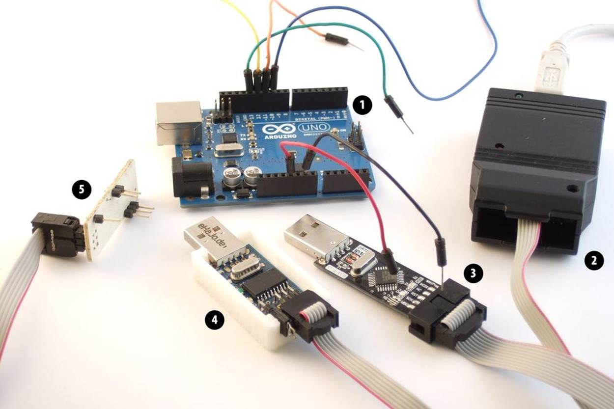
Figure 2-4. Some programmer options
Hookup
The overview of wiring for this chapter is that we’re going to be hooking up the programmer (including its power-supply pins) to the AVR chip. Each of these pins has a specific function, and they’re labelled in Figure 2-5. The whole point is to make sure that the programmer’s MOSI pin is connected to the AVR’s MOSI pin (PB3) and so on. We’ll also wire up an LED for display purposes, and optionally wire up another as a power-on indicator.
If you’re using an Arduino as your programmer, your wiring will end up looking like Figure 2-3, but you can also assemble the circuit piecewise as we’re doing here. First hook up the power and verify that it’s working, and then move on to the MOSI, MISO, SCK, andRESET wires. The principle is exactly the same.
For the first step, let’s set up the power rails of your breadboard to double-check that we’ve got the pinout from the programmer’s connector right. You’re going to need some red wire for 5 V and some black wire for GND. If you’re using an Arduino as programmer, the 5 V and GND connections are nicely labelled on the board. Use red and black wires to hook them up to the breadboard’s power rails.
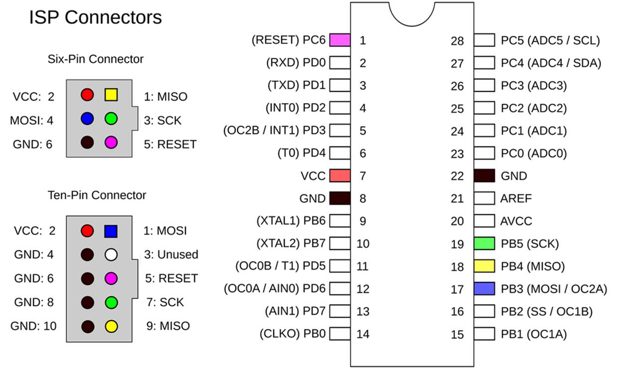
Figure 2-5. AVR ISP programming pins
If you’re using a programmer that ends in a standard 6-pin or 10-pin two-row IDC connector, getting the pinout correct can be a little bit tricky. For orientation, set the connector on the table so that you’re looking down into the holes, and notice the location of the plastic tab. The cable should also have a red stripe on the same side that has the VCC pin, which is a very helpful mnemonic. Hook up the power pins so that they look like Figure 2-6.
If you’re going to use a power-on LED, now’s the time to plug it into the board to verify that you’ve got power. Wire it up as in Figure 2-7. Note that LEDs are polarized, and you’ll need to make sure that the positive side is connected to VCC and the negative to ground. You can recognize the negative side of an LED by its shorter pin (think of it as the “minus” side having something subtracted from its length), or by the slight flat spot on the flange of round LEDs, or by the larger structure inside the LED itself. Connect the resistor up to the negative pin.
Plug your USB programmer into your computer. If the LED glows, the power supply is ready to go. If not, and you’re using a programmer like the USBTiny, you may have to install a jumper across two pins to enable the power-supply passthrough. (See the instructions that came with your programmer for how to make the programmer supply power to the AVR.) If this still isn’t working, double-check your 6-pin connector again. After you’ve gotten the power-on LED light working, you know for sure that you’re getting power on the breadboard’s supply rails.
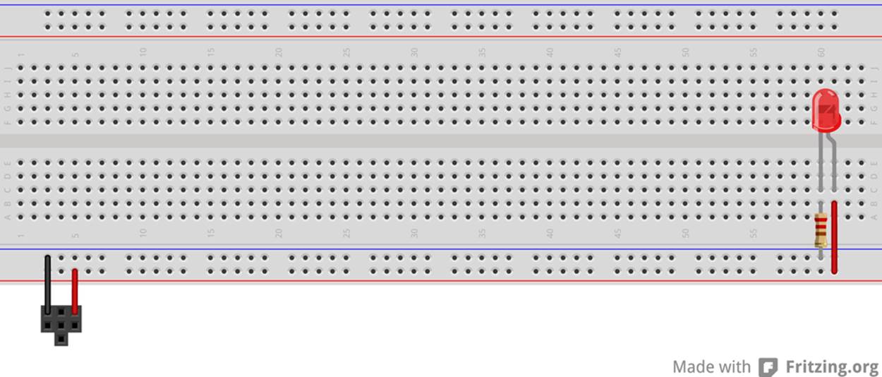
Figure 2-6. AVR programmer layout—no chip yet
Now plug the AVR somewhere in the middle of the board. Locate pins 7 and 8, which are power and ground for the chip, and plug a 100 nF (0.1 µF) capacitor across the two power pins. Using a red wire, connect pin 7 to the VCC rail. Wire up pin 8 with a black wire to the GND rail. Now you’ve completed the setup in Figure 2-7.
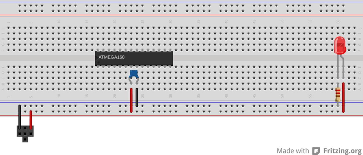
Figure 2-7. AVR programmer layout—power
Now hook up the rest of the programmer’s pins. Look carefully at Figure 2-5 if it’s not clear which pins are which. Double-check that MOSI on the connector is wired to MOSI on the AVR, etc. Finally, connect up the demo output LED and its resistor as shown inFigure 2-8. When you’re done with this, we’re ready to test it out.
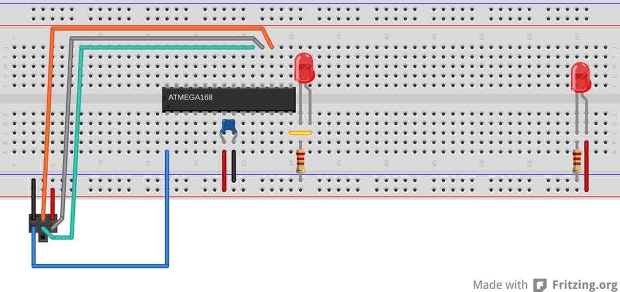
Figure 2-8. BlinkLED full setup
ISP Headers
The Atmel-standard 6-pin and 10-pin headers are nice for manufactured boards because they’re compact, but they’re not at all breadboard-friendly, and that’s why we end up with all these wires all over. Sparkfun (and probably others) sell adapters that convert the 5 × 2 and 3 × 2 layouts into a 6 × 1 inline layout that plugs nicely into the breadboard and labels the signal lines as well. If you’re ever placing an order with them, these little tools are well worth a dollar.
Alternatively, you can take some perfboard and wire up a similar breakout yourself. You’ll need a bunch of breakaway header pins, a bit of wire, and some patience. Make sure you test and label the outputs when you’re done.
For the long run, I’d recommend making yourself a programming adapter of some kind. The idea is to hardwire up a connector that either plugs into a breadboard or sits on top of the chip that you can use to replace the multiple wires that connect the programmer to the chip. Figure 2-9 demonstrates a variety of ways to simplify connections between your AVR and programmer.
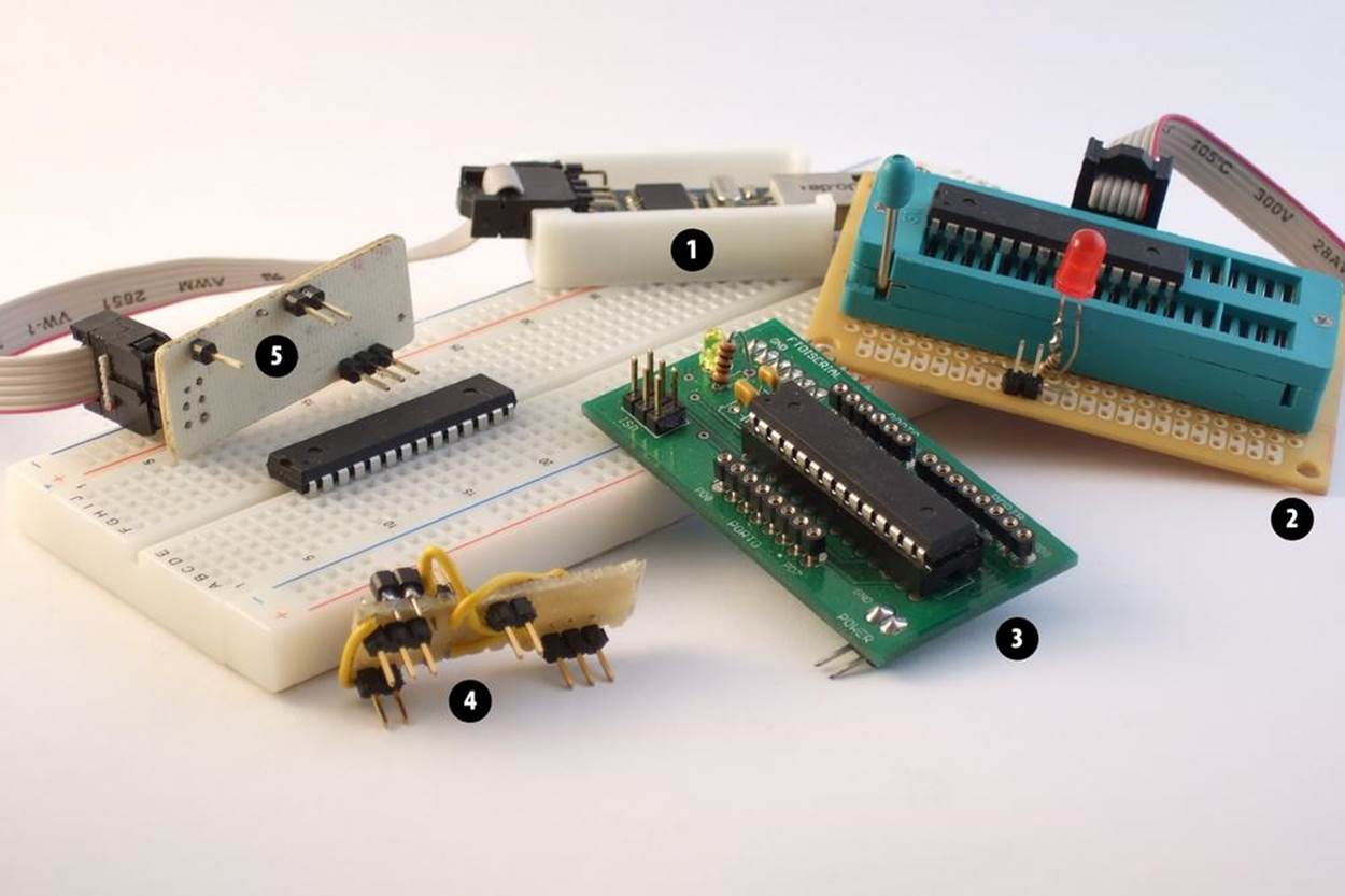
Figure 2-9. Programming adapters for ISP 6-pin headers
From the top, going clockwise:
1. A USBTiny programmer with the standard 6-pin ISP header.
2. A zero insertion force (ZIF) socket that I wired up to connect to the 6-pin ISP header and the ATmegax8 series chips. For fun, I also added a power-on LED and an external power connection so that it can work with nonself-powered flash programmers. You can find ZIF sockets cheap at online auction sites. The underlying perfboard came from Radio Shack.
3. Next is a (deluxe!) custom board that I had made as a precursor to a board I used in teaching an AVR class. This one breaks out all the ports into banks, has a 6-pin SPI header, an external power connector, on-board capacitors and power lights, and a 6-pin inline header that’s compatible with the FTDI USB-Serial cable pinouts.
4. On the bottom is an experimental 6-pin ISP adaptor that just barely squeezes on top of an AVR chip, holding itself in place by bending the pins a little bit. I got the idea from http://elm-chan.org/works/avrx/report_e.html, but I added on a serial interface as well. It’s hard to maintain contact with all the pins at once, and I only use this connector in emergencies.
5. Last, on the far left, is the homemade programming spider that I use almost all the time. It plugs into a breadboard just around the AVR and connects up everything you need to flash the chip. It’s the bee’s knees, and if you’re handy with a soldering iron or looking for an excuse to learn, making a connector like this is well worth your time.
AVRDUDE
After you’ve gotten the circuit breadboarded and the AVR connected up to the programmer, you’re ready to start talking to the AVR to test the connection. And, believe it or not, the easiest way to do this is to type a little bit.
Open up a command-line window. If you’re in Linux or Mac OS, open up Terminal. For Windows, open up a Run dialog from the Start menu, type in cmd, and hit Enter. You can then type avrdude to double-check your installation. You should see a helpful listing of all the command-line flags and arguments that you can use. You can read up on the most useful ones in AVRDUDE Options.
If you don’t get AVRDUDE running from the command line, you’re going to need to make sure that it’s installed and that your OS knows the correct path to find it. If you’re on Windows, the easiest way is probably to uninstall WinAVR and reinstall, allowing it to set up the PATH variable for you this time. Linux and Mac people should not have this issue.
AVRDUDE OPTIONS
Whoa! That’s a lot of choices. Let’s look at a few of the ones that we’ll use:
-c <programmer>
Here you specify the type of flash programmer that you’re using. Many serial programmers, including the ArduinoISP, use the generic avrisp type (not the arduino type, which programs the Arduino itself). There are also configurations for both usbasp and usbtiny programmers. If you’d like to see the full list, type avrdude -c ?.
-p <partno>
Here you specify the type of AVR chip that you’re programming for. In our case “m168” is an ATmega168 chip or “m168p” if you’ve got that version.
-P <port>
If you’re not using a native USB programmer (for instance, if you’re using an ArduinoISP), you’ll need to know which serial port the programmer is connected to. See Common AVRDUDE Configurations for details. On Windows, it’s usually something like COM3; on Linux and Mac OS, it’s in the /dev/tty* lineup.
-b <baud>
This sets the baud rate if you’re using a serial programmer. You’ll have to know what speed your programmer wants, or use trial and error.
-n
Write-nothing mode. This one lets you test out commands without worrying that you’ll accidently mess up the chip.
-t
Terminal mode. This mode lets you talk to the AVR chip directly. After the programmer has connected, type sig to read the AVR’s device signature, which makes a quick test of basic communication between the programmer and chip. Type help to see all the options.
-C <config-file>
This lets you use a nonstandard configuration file. If the version of AVRDUDE that you’ve got doesn’t support a particular chip or programmer, you can often fix it by getting a more recent configuration file. I’ve included mine in the book’s software bundle.
-U
This the command that reads or writes to memory. You’ll almost always be calling this from a makefile, but if you’d like to dump the memory of an AVR chip to a file, or flash in a .hex file that someone has already compiled for you, this is how you’d do it.
DRIVERS AND WINDOWS
If you’re running Windows, you may not automatically have the correct drivers for your programmer installed. This is notably the case with Windows Vista and Windows 7 and the USBTiny and USBasp type programmers. If you get a warning message like “usbtiny device not found,” it’s very likely that your drivers aren’t set up right.
You should probably follow whatever instructions your programmer comes with. For me, I had to download a newer libusb from LadyAda’s website, install it, and then do a manual install of the USBTiny drivers through the Device Manager. This step is no fun, but you only have to do it once.
Now let’s try to talk to the programmer directly. Type something like avrdude -p m168p -c usbtiny to interrogate the chip (only substitute your programmer in place of the “usbtiny”) and optionally add a serial port and baud rate. If all is hooked up well, it will respond with something about the chip’s signature and fuses and say OK. Success looks something like this:
avrdude: AVR device initialized and ready to accept instructions
Reading | ################################################## | 100% 0.01s
avrdude: Device signature = 0x1e9406
avrdude: safemode: Fuses OK
avrdude done. Thank you.
AVRDUDE errors
On the other hand, you might get an error. There are basically four possible errors you’ll get, depending on whether you’ve messed up the wiring, specified the wrong chip or programmer type, or don’t have adequate permissions to use the interface. Let’s break them down into cases.
You get an an error that reads:
avrdude: initialization failed, rc=-1
Double check connections and try again, or use -F to override
this check.
The dreaded rc=-1 error message means that your wiring is messed up. Despite what it suggests, using -F won’t help you—99.9% of the time when you see this error, your problem is that the six wires connecting your programmer to the AVR chip aren’t hooked up right. This error can occur when you don’t have power to the chip, when any of the RESET, MISO, MOSI, or SCK lines aren’t connected properly, or even if you’ve got something else plugged into any of these pins that’s interfering with your setup. Double-check everything until the problem is fixed; maybe even unplug and replug your USB programmer.
You get an an error that reads:
avrdude: Device signature = 0x1e9406
avrdude: Expected signature for ATmega168P is 1E 94 0B
Double check chip, or use -F to override this check.
This probably means that you’ve got the AVR chip type wrong. In the previous example, I used a mega168 but told it I had a mega168P. In this case, you just need to change the chip type that you’re passing as an argument to AVRDUDE. If AVRDUDE doesn’t have a configuration for the chip you’re using, you should try using a newer (or custom) configuration file with the -C flag (see AVRDUDE Options).
The other source of the Expected signature error is that there’s something wrong with the communication channel. If the programmer sees a signature like 0xffffff or 0x000000 or the signature changes from one trial to the next, you’ve most likely got something wired up to your ISP lines that’s blocking the communications, or you’ve got a loose wire. Fix these problems and try again.
You get an an error that reads:
avrdude: stk500_recv(): programmer is not responding
avrdude done. Thank you.
or:
avrdude: error: could not find USB device with vid=0x16c0 pid=0x5dc
vendor='www.fischl.de' product='USBasp'
or:
avrdude: Error: Could not find USBtiny device (0x1781/0xc9f)
This means AVRDUDE is having trouble finding your programmer. In the case of a serial programmer like when you’re using the Arduino, double-check the serial port and baud-rate flags that you’re passing to AVRDUDE. If you’re using a USB programmer, make sure that it’s recognized by the system. On Linux you can type lsusb and look for the programmer in the list. On Windows, check for it in the Device Manager.
Finally, if you’re on Linux and you receive a permissions error, you can fix it by typing sudo avrdude instead of avrdude. When you get tired of the extra typing, you can give yourself permission to write to USB serial ports. In Ubuntu-like distributions, this means adding yourself to the dialout group. For all flavors of Linux you could alternatively write a udev script for the specific programmer. You’ll find specific directions online if you search “avrdude udev” and your programmer type.
COMMON AVRDUDE CONFIGURATIONS
AVRDUDE supports more than 70 programmers and 100 chip types, and runs on three different operating systems, so the number of possible configurations is ridiculous. Here are some examples of the types of configurations that you’ll encounter to get you started:
Windows, Linux, or Mac OS with USBTiny, ATmega168P
avrdude -p m168p -c usbtiny
(Because USBTiny and USBasp programmers don’t need any additional options, the command is the same across all three operating systems.)
For the following, you need to type the commands all on one line:
Windows with ArduinoISP, ATmega168p
avrdude -p m168p -c avrisp -P com5
-b 19200
Linux with ArduinoISP, ATmega168p
avrdude -p m168p -c avrisp -P
/dev/ttyACM0 -b 19200
Mac OS with ArduinoISP, ATmega168p
avrdude -p m168p -c avrisp -P
/dev/tty.usbserial-A5307bQf -b 19200
ArduinoISP needs the -P flag for the serial port. To find out which serial port you need, open up the Arduino IDE and look under Tools → Serial Ports with the Arduino plugged in. (The Arduino plugs into USB, but it’s got an onboard serial emulator that makes it show up as a serial port device.)
Windows with parallel port programming cable, ATmega88
avrdude -p m88 -c dapa -P lpt1
Linux with parallel port programming cable, ATmega168p
avrdude -p m88 -c dapa -P /dev/parport0
I hope these examples get you squared away, or at least put you on the right path. If not, an Internet search will probably yield results. In most all situations, just a couple of tweaks to the same basic command options will work.
Configuring Your Makefile
Playing around with AVRDUDE by itself is good for debugging and making sure everything works, but you’d hate to have to remember all this, much less type this all out every time. And that’s where the makefile comes in.
As mentioned in Make and Makefiles, most of the makefile is generic info for the compiler about how to compile and link program files for the AVR, and you’ll never need to modify these generic bits. On the other hand, the top few lines include some definitions that are specific to the project at hand and to your compilation and flash programming setup. We’re going to need to edit some of these by hand. Copy the blinkLED folder from the book’s source code library and open up Makefile with your programming editor. Let’s step through the bits you’ll need to change:
MCU
This is the type of AVR chip you’re using. In our case, we’re using an ATmega168, so it reads atmega168. For a complete list of supported chips, type avr-gcc --target-help and about halfway down you’ll find a list of “Known MCU names.”
F_CPU
This definition tells the compiler what clock speed your chip is running at. If you don’t have an external clock source, like a crystal, this is either 1,000,000 or 8,000,000 for the ATmega chips—one megahertz or eight megahertz. Getting this right will matter for the timing of serial communication, and anything else where timing is key.
BAUD
This is the baud rate that you’re going to use for computer-to-AVR serial communications, and 9,600 baud is a good conservative default.
MAIN
This entry is just the name of the program that you’re compiling and flashing—the code that contains the main() routine. I’ve filled this in for you in the book’s projects, but if you want to start a new project from scratch but reuse this makefile, you’ll need to change the MAIN.
LOCAL_SOURCE
Here you have the chance to list any other .c files that your main code section needs to run. Again, I’ve filled these in for the book’s projects, but I mention it here in case you’d like to see how to include multiple files in your compilation.
EXTRA_SOURCE_DIR and EXTRA_SOURCE_FILES
This is an option to include code that lives in another directory or folder somewhere on your system. We’ll use this a lot for including my USART.h standard serial library.
PROGRAMMER_TYPE
The two “programmer” options are for AVRDUDE, along with information about what chip we’re programming from MCU. Here, you enter the type of flash programmer that you’re using, and the makefile passes it to AVRDUDE using the -c option. If you’re using a USBTiny or USBasp, for instance, you enter that here. If you’re using the Arduino as a flash programmer, enter avrisp.
PROGRAMMER_ARGS
The other “programmer” option is for any of the other necessary AVRDUDE options. If you’re using a USBTiny or USBasp, you won’t have to enter anything here; just leave the line blank. If you are using a serial-based programmer, you’ll need to specify the serial port and baud rate using the -P and -b options, respectively.
See Common AVRDUDE Configurations for hints, or scroll down to the very bottom of the makefile to see some examples for common programmers and configurations. And remember, this is just passing these options on to AVRDUDE, so whatever it took to get AVRDUDE working on the command line (except for processor and programmer type), you’ll need to add in here.
Flash
OK, by now you’re dying to see some blinking lights. I can’t blame you. If you’ve already got a command-line window open, change directory to the blinkLED project and type make flash. If all of the preparations up to now went well, congratulations! Your sweet reward is a slowly blinking LED on the breadboard!
You want more? Open up the blinkLED.c file in your editor, and read through. Try changing the delay times to change the blink rate of the LED—for instance, make it blink on for just a very short time between long periods of being off. Each time you edit the code, save it and then type make flash again. Or if you’re using an editor that lets you compile and flash from within it, it’s even simpler.
Take the time now to get used to the “edit-compile-flash” cycle, while the toolchain is unfamiliar but the code is simple. Once the code and/or the circuits start to get complicated, you’ll be glad to have faith in the toolchain.
Troubleshooting
We did most of the troubleshooting for this project as we went along. Is the power working? It should be, as long as the power LED is lit. Does the AVR receive this power? A quick way to double-check is to put an LED across the AVR power pins, where you’ve got a capacitor.
The next things to check are the connections, because it’s easy to get these wrong. But because we tested them using AVRDUDE, we know that the programmer is able to communicate with the AVR chip, so all should be well.
So with the hardware all debugged, that only leaves the software, and in this case, it’s about as simple as can be. What’s more, I’ve double-checked it about a billion times, so it should compile just fine. (Barring the pindefs.h problem if you’re using an Arduino IDE for compiling, in which case see portpins.h and the Arduino IDE.)
Because everything’s working just fine, a good exercise at this point is to break the code and see what happens. C compilers are great when it comes to complaining that something’s wrong, but not as helpful as you’d like when it comes to pinpointing the cause of the error. For instance, pick a line of code that ends with a “;” and delete the semicolon. Save the bad code and type make to see what happens. All sorts of errors, no? But none of them tell you “you deleted a semicolon.” Learning to deal with the error messages is an important part of coding.
If you deleted a semicolon as suggested, you’ll probably see an error like:
blinkLED.c: In function ‘main’:
blinkLED.c:22:5: error: called object ‘_delay_ms(1.0e+3)’ is not a function
The compiler is telling you that something went wrong around line 22 in the code, specifically something that starts at line 22, column 5. It doesn’t know there’s a missing semicolon, but it gets you in the right neighborhood. This is where you have to do a little detective work. (The meaning of the error is that lines that look like something() without a semicolon at the end are supposed to be function definitions, but in this case it’s not. The compiler can’t know that you meant use a function rather than define one if you don’t add that semicolon on the end.)
It could be worse. Sometimes there will be a string of many errors all in a row. Don’t give up! It’s not necessarily the case that you made many errors, but maybe the first one caused a bunch of follow-on problems to arise. If the compiler gives you multiple errors, it’s often a good idea to start fixing the first one (by line number) and then see if that resolves the rest.
Anyway, fix up that semicolon and reflash your valid code with a make flash. Notice what a successful flashing looks like. Heck, if you’re feeling nerdy, scroll back up to see the exact string of commands the makefile ran on your behalf and revisit Make and Makefiles. If you just want to get on with more programming, and everything worked, we’re done here.
All materials on the site are licensed Creative Commons Attribution-Sharealike 3.0 Unported CC BY-SA 3.0 & GNU Free Documentation License (GFDL)
If you are the copyright holder of any material contained on our site and intend to remove it, please contact our site administrator for approval.
© 2016-2026 All site design rights belong to S.Y.A.