Make: AVR Programming (2014)
Part I. The Basics
Chapter 6. Digital Input
AVR Music Box and a Boss Button
If you want to build a standalone AVR device, there’s no substitute for the tried-and-true pushbutton. Look around the room you’re now in. How many electronic devices with pushbuttons are you surrounded by? (Feel free to stop counting after five or ten.) Pushbuttons are cheap, ubiquitous, and the natural choice for quick and mostly painless human/AVR interaction.
In this chapter, we’ll take the humble pushbutton as a stand-in for all types of digital input, but there are also a few quirks in using pushbuttons that you will need to know about. Most importantly, they often bounce very rapidly between the on and off states when pressed or released. Additionally, you’re often interested in running some action when the button is first pressed rather than continuously while it’s pressed.
WHAT YOU NEED
In this chapter, in addition to the basic kit, you will need:
§ A pushbutton or two.
§ A speaker and blocking capacitor, around 10 uF.
§ A USB-Serial adapter.
Pushbuttons, Switches, Etc.
As soon as you start having plans for more interesting AVR devices, you’re going to want some degree of user interaction. And what’s simpler than the humble pushbutton? Still, there are a couple of things you’re going to need to know before you can start using switches and buttons as inputs to the AVR.
The AVR inputs are good at sensing voltages. In particular, they’re very good at sensing whether an applied voltage on a particular pin is higher or lower than half of the supply voltage. Your first task, then, is to figure out how to apply logic high and low voltages to an AVR pin by way of a pushbutton.
The naïve circuit shown in Figure 6-1 connects one end of the pushbutton to ground and the other end to the AVR. That way, whenever you press the button the AVR end is connected to ground, too, so it’s pretty much guaranteed to be at 0 V.
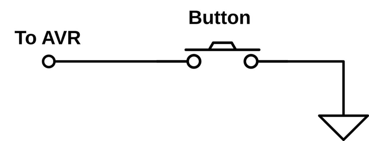
Figure 6-1. Naive button circuit
But when you let go of the button (or open the switch), what is the voltage at the AVR end of the switch? Short answer: nobody knows. A wire that’s just dangling in the air, on the unconnected side of a switch, can act as an antenna. The voltage on that wire will wiggle around between high and low logic states at whatever frequency the strongest local radio stations (or even “noisy” electrical appliances) broadcast. The only thing you do know about this voltage is that it’s unreliable.
Instead of some random value, you want the side of the button that you connect to the AVR to have a nice, defined high voltage level when the button isn’t pressed. But you can’t hook the AVR-side of the button directly to VCC, because if you did, you’d be shorting out the power supply when you pressed the button—hooking VCC up directly to GND is a recipe for disaster. Enter the pull-up resistor, shown in Figure 6-2.
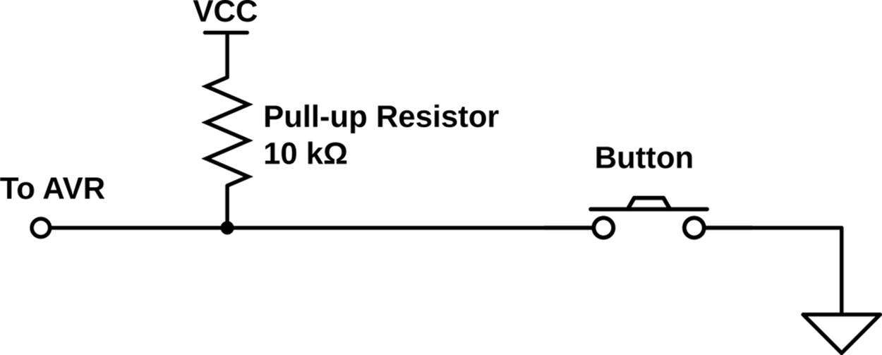
Figure 6-2. Pull-up resistor button circuit
A pull-up resistor is a resistor of a relatively high value that “pulls up” the nonground side of the button to the high voltage level in the absence of a button press. Think of pull-up (or pull-down) resistors as setting a default electrical value for the button when it’s not pressed.
Relatively large-valued resistors (10k ohms–100k ohms) are used for pull-ups so that when the switch is pressed, it creates a lower-resistance path to ground, and only a small amount of current will flow through the circuit. If the pull-up’s resistance is large enough, the voltage seen by the AVR will be very close to 0 V.
Now here’s the cool bit. The AVR chips provide you a built-in pull-up resistor for each pin, and you have the option to activate it for any pin that is in input mode. That way the AVR side reads a well-defined high voltage level (pulled up by the internal resistor) until you press the button, when the lower-resistance connection to ground through the button dominates, and the pin reads 0 V. The final circuit with the AVR’s internal pull-up resistor enabled is shown in Figure 6-3.
So in the end, it looks like we’re back to the naïve circuit from Figure 6-1, with the exception that this one will actually work as intended, thanks to the AVR’s optional internal pull-up resistor. Add the button to your breadboard as in Figure 6-4 (pushbutton to pin PD2), and let’s get to configuration. (Leave the LEDs and everything else you’ve got on the board in place.)
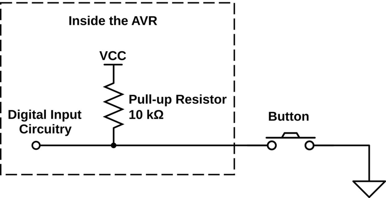
Figure 6-3. AVR circuit with internal pull-up resistor enabled
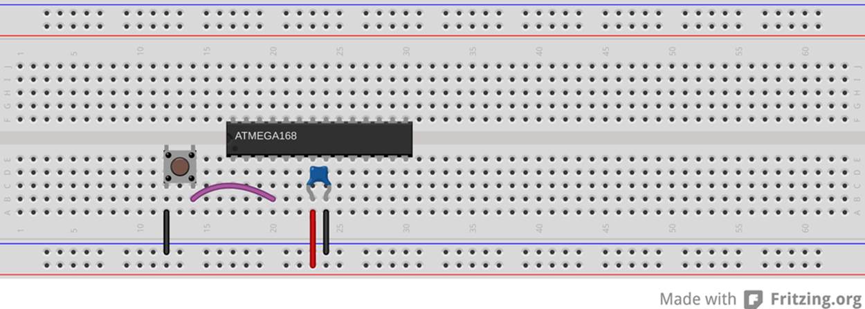
Figure 6-4. AVR with pushbutton
Configuring Input: DDRs, PORTs, and PINs
Just as you can configure the AVR’s pins for output, you can also set the data direction registers to enable the pins as inputs. Only this time it’s a lot easier—input is the default mode for the chip. If you haven’t touched the DDR yet, you’re already in input mode. Otherwise, you can select input mode for a pin at any time by clearing the bits that correspond to your pins in the right DDR.
Suppose you want to read the state of pin PD2, the pin that you’ve connected to your pushbutton. When the chip powers up, every pin is already in input mode, so all that remains is to enable the pull-up resistor. And to enable the pull-up, unsurprisingly, you need to set a bit in a hardware special register.
But the surprise is which hardware register you need to set a bit in: the output pin hardware register. That is, if you’d like to enable the pull-up on PD2, you need to set PORTD’s corresponding bit high:
DDRD &= ~(1 << PD2); // makes double-sure we're in input mode
PORTD |= (1 << PD2); // enables pull-up resistor
The way I remember this is that writing a bit to the PORTD register when it’s configured for output would pull the pin high, so doing the same when it’s configured for input also pulls it high, but only weakly—that is, through the pull-up resistor.
You might be wondering why the Atmel engineers would reuse the same hardware register for both setting the output value in output mode and for enabling or disabling the pull-up resistor in input mode. Well, me too. My only guess is that it costs them more space in the IC’s internal circuitry to set up another dedicated eight bits of memory for (yet another) register. Because you’re never going to have a given pin both in output and input mode, they can use the PORT registers to do double duty. The point is, though, that you’re going to have to remember this double role of the PORT registers in input mode.
Great. So you’re configured. Now how do you access the bits? Very similarly to how you wrote to them: reading out a byte from a hardware register and doing some bit twiddling. Only this time you’re twiddling the input hardware register address: PIND. (Think "PinINput D.”)
Let’s say that you haven’t attached anything to any of the other pins in bank D except for your pushbutton on PD2. Further, you’ve just reset the chip, so all of the pins are in input mode. One more thing: let’s write a 1 to all the bits in PORTD, enabling all of the pull-ups:
DDRD = 0x00; // all pins in input mode, just to be sure
PORTD = 0xff; // all pins pull-ups enabled
If you look at the eight bits in PIND, you’ll see:
PIND: 11111111
Why? Because nothing is grounded, and the pull-ups guarantee that everything is in logic-high state. Now let’s say you push your button, grounding pin PD2. What happens? All the other bits in PIND stay the same, but because the button has much lower resistance than the internal pull-up resistor, the ground voltage wins out, the voltage on PD2 drops near zero, and PIND reads:
PIND: 11111011
Now you’ve got something you can work with!
Interpreting Button Presses
So you’ve configured the pin with your button for input, you’ve set the pull-up resistor, and you’re ready to go! How do you read the value of a single bit in the register without reading all the others? If your instincts tell you that it’s something to do with bitwise logical operators, you are on your way to microcontroller mastery.
Testing bit states is done with the AND operator. You know that an AND will only return 1 if both bits are 1. If you perform an AND operation in which you compare an unknown bit value against a known 1, you’ll get the state of the mystery bits as the result. So you’ll bit-shift a 1 into the bit location you’re interested in, then AND the two bytes together. The result will either be all zeros if the target bit was zero, or it will be a byte with a 1 in the target location if it was 1.
Testing bits with AND
Say we’re interested in testing if bit two is set. The first step is to create a bitmask with a 1 in bit two:
(1 << 2) : 00000100
Then we AND that byte with whatever is in the input register, PIND:
PIND : xxxxxxxx
(1 << 2) : 00000100
& : 00000x00
If the value we were interested in knowing is a zero, the result is eight zeros. If the result isn’t zero, then we know the pin in the input register must have been set. Voilà!
So we can test this:
if (PIND & (1<<2)){
doStuff();
}
using the C language convention that only a value of zero returns false, and anything else is true.
GCC convenience macros
Because all of this shifting and ANDing can get tiresome, you won’t be surprised that there are some convenience macros defined to help you out. Now I’ve almost never seen other people’s code using these macros, so you’re going to have to remain used to reading the bitmask-and-AND method. These macros are probably not defined by any compiler other than GCC, for all I know.
On the other hand, these macros are in avr-libc for your use, and I do find they lead to nicely readable code. I’ll use them in my code sometimes, but then also use the standard C bitmask method sometimes too just to keep you on your toes.
Helpful input macros (included with avr/io.h):
#define _BV(bit) (1 << (bit))
#define bit_is_set(sfr, bit) (_SFR_BYTE(sfr) & _BV(bit))
#define bit_is_clear(sfr, bit) (!(_SFR_BYTE(sfr) & _BV(bit)))
#define loop_until_bit_is_set(sfr, bit) do { } while (bit_is_clear(sfr, bit))
#define loop_until_bit_is_clear(sfr, bit) do { } while (bit_is_set(sfr, bit))
simpleButton demo code
As a quick example of reading button input, flash the simplePushbutton.c test program into your chip now and then have a look at the code listed in Example 6-1.
Example 6-1. simpleButton.c listing
/*
Demo of the simplest on/off button code
Button connected to PD2
LEDs connected to PB0..PB7
*/
// ------- Preamble -------- //
#include <avr/io.h>
#include <util/delay.h>
int main(void) {
// -------- Inits --------- //
PORTD |= (1 << PD2); /* initialize pullup resistor on our input pin */
DDRB = 0xff; /* set up all LEDs for output */
// ------ Event loop ------ //
while (1) {
if (bit_is_clear(PIND, PD2)) { /* look for button press */
/* equivalent to if ((PIND & (1 << PD2)) == 0 ){ */
PORTB = 0b00111100; /* pressed */
}
else { /* not pressed */
PORTB = 0b11000011;
}
} /* End event loop */
return (0);
}
It’s not all that complicated, so I’m not going to explain it in excruciating detail, but there are two points worth mentioning. First, notice that the code enables the pull-up resistor for the button pin (PD2) by writing to PORTD. In Cylon Eyes, we used PORTB for controlling output state. In input mode, PORTD controls the pull-up resistor.
The second detail is that our logic is reversed. Because a high voltage on the AVR’s pin results in a logical 1 inside the AVR, and the switch voltage is high when the button is not pressed, PIND has a 1 in bit PD2 when the button is not pressed. Contrariwise, when the button is pressed, the bit will read 0. So if you’re testing for a press in an if() statement, you’ll want to use bit_is_clear(PIND, PD2) or equivalently (PIND & (1<< PD2)) == 0 as the test.
CAREFUL WITH THOSE PARENTHESES
Note that I used (PIND & (1 << PD2)) == 0 and not PIND & (1 << PD2) == 0 in the preceding test. This is because the == is evaluated before the & otherwise. If you forget the parentheses, (1 << PD2) == 0 returns zero, and PIND & 0 is also going to be zero, no matter whether the button is pressed or not. The parentheses make it evaluate the & before the ==.
Of course, you can avoid all this thinking and use bit_is_clear() instead, which I find much more readable anyway. (And note that the macro is defined with the outer parentheses for you.)
Changing State
Depending on what your device does, you may be interested in whether the button is currently pressed, or whether the button just got pressed. That is, you may want to know what state the button is in (pressed or not), or you may alternatively want to know that the button has changed state (just got pressed or just released).
Because the English language is a little imprecise on these matters, but the AVR is brutally literal, you’ll need to think like a computer here. When you say “do something if the button is pressed,” you’ll have to think about whether you mean “while the button is pressed” or “when the button enters the pressed state.”
The difference? Imagine that you want to turn on or off an LED with a button press. If you write naïve code:
while(1) {
if (buttonIsPressed){
toggleLED();
}
}
the LED is going to be toggling around 100,000 times per second while you’re holding the button down, and whichever state it ends up in when you let go of the button is pretty much random. This is probably not what you want.
Instead, if you save the current state of the button in a variable, you’ll be able to see when the button changes state easily. The code shown in Example 6-2 toggles the LED every time you press a button.
Example 6-2. toggleButton.c listing
/*
Demonstrates using state to detect button presses
*/
// ------- Preamble -------- //
#include <avr/io.h>
#include "pinDefines.h"
int main(void) {
// -------- Inits --------- //
uint8_t buttonWasPressed; /* state */
BUTTON_PORT |= (1 << BUTTON); /* enable the pullup on the button */
LED_DDR = (1 << LED0); /* set up LED for output */
// ------ Event loop ------ //
while (1) {
if (bit_is_clear(BUTTON_PIN, BUTTON)) { /* button is pressed now */
if (buttonWasPressed == 0) { /* but wasn't last time through */
LED_PORT ^= (1 << LED0); /* do whatever */
buttonWasPressed = 1; /* update the state */
}
}
else { /* button is not pressed now */
buttonWasPressed = 0; /* update the state */
}
} /* End event loop */
return (0); /* This line is never reached */
}
In this code, the state of the button after the last pass through the event loop is stored in the variable buttonWasPressed. If the button is pressed right now, but it wasn’t pressed the last time we looked, then we know that there’s been a change of state—the button has just been pressed. In this code, we toggle an LED, but you can imagine doing something fancy.
Debouncing
If you play around with the toggleButton.c code for long enough, it will glitch. That is, you’ll press the button, and instead of turning the LED on, it will turn on and then off again so quickly that you might not even see it. But the end effect will be that you thought you were turning the LED on, and it didn’t go on.
Or sometimes it’ll happen that you’ve just turned the LED on with a press, and then when you release the button, it turns back off again. Is there a bug in the code? Nope. You’re just suffering from button bounce.
When you press a switch closed, two surfaces are brought into contact with each other. Often they don’t fit together quite perfectly, and electrical contact will get made and unmade a few times before you’ve smooshed the two plates together firmly enough that a good reliable connection is made. The same is true when you release a button, but in reverse. You let go, the plates start to separate, but one gets a little sideways and just taps the other before they’re far enough apart that they never touch.
This physical open-close-open-close nature of switches makes the voltage on the circuit bounce between high and low logic voltages over a timescale from a few microseconds to a few milliseconds. The really annoying thing about button bounce is that most of the time it doesn’t happen. You can test your button 10 times and declare it working, only to have it bounce on the thirteenth press.
Figure 6-5 displays two oscilloscope traces from the pushbutton on my breadboard. Because the button is normally held high by the AVR’s internal pull-up resistor, the first frame represents a button press while the second is a button release. I’ve cherry-picked two of the worst examples just for you.
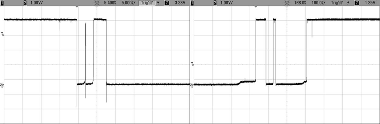
Figure 6-5. Pushbutton bounce example
So that’s what’s going on with our toggling code! When we release the button, for instance, it can momentarily go high and then low again before finally taking the correct high voltage value. If the AVR is checking the button state frequently enough, it can see this high-low transition that occurs during the release bounce and interpret it as a button press, even though no human could ever release and then repress a button that quickly.
The easiest solution is to have the AVR wait a few milliseconds and then check to see if the button is still pressed or not before making any decisions. Because the buttons bounce only for a “short” time, waiting for a little bit longer and then double-checking will ensure that we’re not mistaking bounce for a true change.
The trick with debouncing-by-waiting is getting the timing right. The characteristic time that a switch bounces varies from switch to switch, but all that I’ve ever seen settle down within a couple milliseconds. We can therefore very conservatively wait around 5 ms and test the button again. Bearing in mind that human response time is on the order of tens of milliseconds, this won’t result in a noticeable delay to the user, either. Of course, I recommend varying the wait time and trying it out in your particular setup.
(MORE THAN) ALL YOU EVER WANTED TO KNOW ABOUT DEBOUNCING…
You can find a nice writeup of debouncing at http://www.ganssle.com/debouncing.htm, and a compilation of software debouncing routines on http://hackaday.com/2010/11/09/debounce-code-one-post-to-rule-them-all/. Both are good reads.
Debounce Example
So let’s add a debouncing routine to our toggleLED code. The result is shown in Example 6-3.
Example 6-3. debouncer.c listing
// ------- Preamble -------- //
#include <avr/io.h>
#include "pinDefines.h"
#include <util/delay.h>
#define DEBOUNCE_TIME 1000 /* microseconds */
uint8_t debounce(void) {
if (bit_is_clear(BUTTON_PIN, BUTTON)) { /* button is pressed now */
_delay_us(DEBOUNCE_TIME);
if (bit_is_clear(BUTTON_PIN, BUTTON)) { /* still pressed */
return (1);
}
}
return (0);
}
int main(void) {
// -------- Inits --------- //
uint8_t buttonWasPressed; /* state */
BUTTON_PORT |= (1 << BUTTON); /* enable the pullup on the button */
LED_DDR = (1 << LED0); /* set up LED for output */
// ------ Event loop ------ //
while (1) {
if (debounce()) { /* debounced button press */
if (buttonWasPressed == 0) { /* but wasn't last time through */
LED_PORT ^= (1 << LED0); /* do whatever */
buttonWasPressed = 1; /* update the state */
}
}
else { /* button is not pressed now */
buttonWasPressed = 0; /* update the state */
}
} /* End event loop */
return (0); /* This line is never reached */
}
The debouncer.c code here is almost exactly the same as that in the bouncy toggleButton.c earlier. The debounce() function is new, I added a definition for the debounce delay, and I changed the line:
if (bit_is_clear(BUTTON_IN, BUTTON)){
to:
if (debounce()){
but that’s it. All of the rest of the logic of the code (in particular, keeping track of the button state) is just the same, so you don’t have to rethink that through.
TO DEBOUNCE, OR NOT TO DEBOUNCE?
As much as I love debouncing routines (and I love them a lot!) there’s a time and a place for everything.
To debounce
Fundamentally, you need to debounce whenever you’re counting button press events. This goes equally for on/off toggling, scrolling through elements of a menu, or switching among modes.
You’ll also want to debounce if you’re timing an event. How long was the button pressed? Well, that will depend on when you define the button press as beginning. If you accidentally time one of the early spikes, you might erroneously conclude that the user pressed and released the button within microseconds, when it was just a bounce.
Not to debounce
If you don’t care about counting button presses or events, there’s no need to spend the code on debouncing. For instance, if you’d like a circuit to light up when you press a button, a simple logic test will suffice. If your LED blinks a couple times during the first few microseconds, but it’s faster than a human’s flicker-fusion rate, nobody will notice.
Similarly, if you’ve got a built-in delay, the bounce may not matter as much. If your code is doing a lot, and only makes it through the main event loop once in a few milliseconds, then you don’t really have to worry about debouncing—the delay you would have written into your debounce code is already built in to your (slow) main event loop.
Hardware debouncing
There’s also a third option, and this is the way buttons were debounced in the old days before microcontrollers reduced the issue to just a few extra lines of code. Putting a capacitor across the two contacts of a switch forces the voltage to rise slowly, and can ensure that it will not jump up and down along the way. In industry, almost everyone debounces in code, saving a few cents per capacitor.
The debounce() function handles debouncing in the simplest way possible—checking if the button is pressed twice with a delay in between. The function returns a one only if the button was pressed both times. If the button wasn’t pressed for either of the two checks, debounce() returns a zero, and the if(debounce()) statement is false. This, for a long-enough value of the defined DEBOUNCE_TIME, guarantees debounce-free toggling.
Try it out and see. I’ve defined the debounce timeout in microseconds (millionths of a second), which will enable you to experiment. You can set the delay short enough that your button still bounces, and then you can adjust it so it doesn’t. I encourage you to play around with it. For instance, my button still bounces sometimes at 200 microseconds, but doesn’t seem to at 700 microseconds. Even 1,000 microseconds, or one millisecond, is very, very fast on human timescales. Your mileage will vary. Play around.
Just to reiterate, debouncing can be as simple as waiting a fixed time and retesting the button. It’s a good thing to know about debouncing, and to understand that it’s no big deal. If you didn’t know, and you were trying to debug an infrequent glitch like switch bounce in your system, you’d be pulling your hair out.
AVR Music Box
Here is a simple musical application of everything that you’ve learned so far. We’ve all seen music boxes, right? The ones with the small crank on the outside that turns a drum that plucks little tines to play a song? When you turn the crank faster or slower, you can influence the tempo of the song, but the notes are “hardcoded” in to the pins on the turning drum.
You can easily do the same with the AVR: you already know how to play notes so all that’s left is using the pushbutton to allow you to control the tempo. If you’ve got the speaker and blocking capacitor and the pushbutton set up, there’s nothing more for you to do other than flash in this simple code.
The Code
This code is basically just a small tweak on the serial organ in Chapter 5. It calls the same playNote() that we used in the organ routine repeatedly, each time with a different note. The notes themselves are stored in an array called song[]. Each time you press the button (that is the button state changes to pressed), a variable is incremented that points to the next note in the song. While the button is held down, the same note continues to play. This gives you total control over both the tempo and duration of each note.
Flash it in, play around, and see if you can figure out what the tune is! Once you do, feel free to extend the song[] array to play anything you want. The code for the example is found in Example 6-4.
Example 6-4. avrMusicBox.c listing
// Music Box Input Demo
// ------- Preamble -------- //
#include <avr/io.h>
#include <util/delay.h>
#include "organ.h"
#include "scale16.h"
#include "pinDefines.h"
#define SONG_LENGTH (sizeof(song) / sizeof(uint16_t))
int main(void) {
const uint16_t song[] = {
E6, E6, E6, C6, E6, G6, G5,
C6, G5, E5, A5, B5, Ax5, A5,
G5, E6, G6, A6, F6, G6, E6, C6, D6, B5,
C6, G5, E5, A5, B5, Ax5, A5,
G5, E6, G6, A6, F6, G6, E6, C6, D6, B5,
/* etc */
};
/* starting at end b/c routine starts by incrementing and then playing
this makes the song start at the beginning after reboot */
uint8_t whichNote = SONG_LENGTH - 1;
uint8_t wasButtonPressed = 0;
// -------- Inits --------- //
SPEAKER_DDR |= (1 << SPEAKER); /* speaker for output */
BUTTON_PORT |= (1 << BUTTON); /* pullup on button */
// ------ Event loop ------ //
while (1) {
if (bit_is_clear(BUTTON_PIN, BUTTON)) {
if (!wasButtonPressed) { /* if it's a new press ... */
whichNote++; /* advance to next note */
/* but don't run over the end */
if (whichNote == SONG_LENGTH) {
whichNote = 0;
}
wasButtonPressed = 1;
}
playNote(song[whichNote], 1600);
}
else {
wasButtonPressed = 0;
}
} /* End event loop */
return (0);
}
The bulk of the main() routine looks just like the toggleButton code, and that’s no surprise. First, the button is tested for input. If it’s pressed, but it wasn’t pressed last time, we advance to the next note. If that takes us past the last note in the song, we loop back to the beginning. Outside of the first-press logic, the code updates the button-press state and plays our note. If the button is not pressed this time through the loop, wasButtonPressed is naturally set to zero.
If you’re new to C, the way the code moves through the song[] array is worth looking at. The number of notes in the song is computed by the #define macro SONG_LENGTH. Why can’t we just use the sizeof() command directly? Because the note values happen to all be 16-bit numbers, and sizeof() returns the number of bytes. So for a 10-note song, sizeof() will return 20. But because I know that I’ve got an array of uint16_t numbers, I can get the number of entries either by dividing by two or dividing bysizeof(uint16_t), which I think makes it clearer why we’re doing the division in the first place.
Also notice that we test for running over the end of the song with:
if (whichNote == SONG_LENGTH) { ...
Remember that arrays start at zero in C. Because of this, if you’ve got a 10-element array, the first element is number 0 and the last is 9. On the one hand, this is hard to remember and is the cause of many off-by-one errors. On the other hand, it makes it super easy to test for whether you’ve gone to far with just a simple test of equality, as we do here.
Finally, the last strange bit about this code is that we start off with the note indexing variable whichNote set to SONG_LENGTH -1. What gives? If you followed the discussion about zero-indexing, you’ll recognize that whichNote is set to the last valid note in the song. I ended up having to do this because of the button-press logic, which updates the song position first, then plays the note afterward. (I suppose I could have changed the logic to update the note when the button is released, but I wanted it to be a mirror of thetoggleButton code.) Anyway, because I wanted the song to start with the first note on reboot, but it advances a note with every press, the solution is to start on the last note so that when you press the button the first time it will wrap around back to the beginning.
And that’s it. The simple button-pressing routine we developed here turns into a music box with very little extra effort. I hope you enjoy the quick demo. Now what can you do with a pushbutton and some quick programming logic?
PUSHBUTTON CHECKLIST
1. Set DDR for input. It’s the default pin state, but if you’re not sure, it doesn’t hurt to set it explicitly with something like DDRD &= ~(1 << PD2).
2. Set the internal pull-up if you don’t have a physical pull-up resistor in the circuit: PORTD |= (1 << PD2).
3. Read the button voltage in your code. If you’d like to test that the button is pressed, you can do so two ways: with something like if(!(PIND & (1 << PD2))) or using the macro bit_is_clear(PIND, PD2), which I find more readable, and less error-prone.
4. Think about whether you want something to happen while the button is pressed, or when it becomes pressed. Store the previous state and test for changes if you’re interested in the latter.
5. If you’re trying to detect a single button-press event, consider debouncing. The simplest way to debounce is to simply wait a few milliseconds and test if the button is still pressed.
Boss Button
While we’re on the topic of pushbuttons and the AVR, I can’t resist but throw in a project that uses the AVR as a frontend for code that runs on your desktop. Why? Because I think it’s awesome to have a pushbutton that opens a web page. So let’s make a quick-and-dirty Boss Button.
What’s a Boss Button? You know, when you’re surfing the Web, or generally goofing off and your boss comes by? You’re going to need to hide the evidence on your computer screen quickly. But how are you going to do this without mousing all around and generally looking klutzy and suspicious? The answer is the Boss Button. One click on your trusty (and totally work-related) AVR microcontroller project that just happens to be sitting on your desk, and your browser is loaded with all sorts of businessy looking stuff.
OK, so that’s the pitch. But once you’re done with this project, you can simply add a few more buttons and modify the desktop code to launch whatever web pages you’d like with each press. You’ll have your own dedicated physical favorite-website-launcher machine.
To open the browser window to a website, we’ll need to do some scripting on the computer side. And for that, we’ll use Python. So if you don’t have Python and pyserial installed on your computer yet, now’s the time. After you’ve got that set up and understood, the rest is child’s play.
If you’re more focused on simply learning the AVR chip than playing around with desktop computer programming, at least take the few minutes to install Python and the serial module (see Installing Python and the Serial Library) because we’ll be using them throughout the rest of the book. But don’t fret—you won’t have to learn Python on top of C unless you’d like to.
Desktop-side Scripting
I do most of my computer-side scripting in Python, mostly because it’s very easy to extend your work from one domain to another. Most of the stuff that’s almost impossible to implement on a microcontroller is trivial in Python (and vice versa). For instance, if you’d like to write a website hit counter that moves a physical arm, it couldn’t be easier—fetching and parsing a web page is easy with Python. Now all that remains is turning the data into a byte or two, and taking care of the physical interfacing with the AVR, which is where it excels.
INSTALLING PYTHON AND THE SERIAL LIBRARY
First off, if you don’t have Python installed already, let’s do that. And even if you do, we’ll need to make sure you’ve got the serial library (confusingly contained in a package called pyserial) installed.
On Linux and Mac OS X
On any modern distribution, you’ll very likely have Python installed, which means that you can simply open up a terminal window and type easy_install pyserial to get the serial port libraries. If your system can’t find easy_install and you’re on a Debian system, try sudo apt-get install python-setuptools. If all that fails, a web search for how to install setuptools on your system should set you straight.
On Windows
The easiest way to go is with ActiveState’s Python distribution. Click on downloads and save the Python 2.7 installer for your system. If in doubt, get the 32-bit version. Run the installer and install in the default directories (Python27). Now you’ll need to get pyserial (the serial port library). Run cmd.exe to get a terminal window and type inpypm install pyserial and you should be all set.
To verify that all’s well, open IDLE, the included GUI editor and shell, and type import serial. If there’s no error, you’re all set.
And if you’re new to Python development, The Python Tutorial is the traditional place to start. But because we’ve got some demo code coming right up, I’d start there for now.
In this project, we’ll be working through two fairly straightforward bits of code. The first is in Python (but you don’t have to worry too much about the details unless you’d like to), and the other is AVR C. Let’s start off with the Python file listed in Example 6-5.
Example 6-5. bossButton.py listing
## Simple demo
## Sits forever listening to serial port
## When you press button, opens website of your choosing.
## Extend this to many buttons and you'll have a physical
## web-launcher.
BOSS_SITE = "http://www.cartalk.com/content/boss-redirect"
## or perhaps more topical...
XKCD = "http://xkcd.com/353/"
SERIAL_PORT = "/dev/ttyUSB0"
BAUD_RATE = 9600
import serial
import webbrowser
sp = serial.Serial(SERIAL_PORT, BAUD_RATE, timeout = 5)
sp.flush()
while(1): # Sit and wait forever
response = sp.read(1) # get one byte
if response == "O":
print "Got OK Byte. Waiting for button press."
elif response == "X":
print "Got Boss Byte! Alarm!"
webbrowser.open(BOSS_SITE)
else:
print "Got nothing. Still waiting."
The first few lines are simple defines. If you’d like your button to open up a different web page, this is where you modify things. If you’re not using Linux, you’ll definitely need to change the SERIAL_PORT line to point to your USB-Serial port. In Windows, it’s going to be something like COM4 or similar. Leave the baud rate as is for now.
One thing that’s marvelous about Python for this type of quick, yet awesome, hack is that most everything is built-in. (Yes, yes, we had to install the serial library, and that was kind of a pain. But from here on, it’s smooth sailing.) For instance, opening a page in a browser requires you to import the webbrowser library and then call webbrowser.open(), and then you’re done. So all you need to do is wait until you get the signal from your microcontroller over the serial port.
And using the serial port in Python is almost just as easy. First, import the serial library. Then, create a serial port object with the location of your USB-Serial adapter, the baud rate, and an optional timeout. When you later ask for a byte over the serial line, this timeout value tells you how long, in seconds, your program will wait until it gives up and returns nothing. I set it to a relatively low five seconds, but you can set it to whatever you’d like. Longer values will just mean fewer messages indicating that the program is still waiting.
The sp.flush() command clears out the serial input and output buffers. Your big computer collects all of the values that it’s seen in a serial buffer and waits for some program to read from it. You don’t want the serial buffer clogged up with other data before you start your program, so you flush it. This step may or may not be necessary on your system, but it won’t hurt.
Then you enter an infinite loop, where you continually read a byte from the serial port and then print messages or open a browser window, depending on the value received from the AVR. You can see how to generalize this to multiple buttons here—for each button, simply send out a different character over the serial line and assign it a different action. Simplicity itself.
Try resetting your AVR by either unplugging its power or temporarily grounding the RESET line, and verify that your Python-side program says that it’s received the OK byte. Now press the Boss Button and smile with glee as it opens up a browser. The power!!!
What’s fun about the AVR code in bossButton.c is that it’s even more trimmed-down than our “simple” loopback routine. Aside from the usual configurations and including the USART files, Example 6-6 lists the AVR-side code.
Example 6-6. bossButton.c listing
/*
bossButton.c
As long as we've got a button wired up to the AVR,
might as well have some fun.
Upload this code to your AVR, run bossButton.py.
Press button.
*/
// ------- Preamble -------- //
#include <avr/io.h>
#include <util/delay.h>
#include "pinDefines.h"
#include "USART.h"
static inline void blinkLED(void) {
LED_PORT = (1 << LED0);
_delay_ms(1000);
LED_PORT &= ~(1 << LED0);
}
int main(void) {
// -------- Inits --------- //
BUTTON_PORT |= (1 << BUTTON); /* input mode, turn on pullup */
LED_DDR = (1 << LED0);
blinkLED();
initUSART();
transmitByte('O');
// ------ Event loop ------ //
while (1) {
if (bit_is_clear(BUTTON_PIN, BUTTON)) {
transmitByte('X');
blinkLED();
}
} /* End event loop */
return (0);
}
Yup. All the AVR does is sit in the event loop, looking for the button press. When it sees a button press, it sends your secret code character “X” and blinks an LED. The Python code on your big computer takes care of the rest. You don’t have to worry about debouncing and sending multiple “X"s per button press either, because you’re delaying for one second per button press, so the AVR basically unburdened.
Extensions
Although the Boss Button application is probably a little bit trivial, it demonstrates some of the real power of connecting your AVR to your computer. If you can serve web pages, you can have them display real-time status from anything you can hook your AVR up to. Any of the further projects we undertake in this book can be trivially webified. Need a remote light sensor? Send the data out from our project in Chapter 7 to a web server. Or tweet it. Or whatever. Your imagination is the limit.
If you’d like to get even fancier, and have the AVR take some of the load, see the example in the pyserial Python module documentation of a serial-to-TCP/IP bridge. Now you can connect to your AVR remotely by accessing the relevant network port. Using this, you can serve web pages directly from your AVR. (That’s overkill in my opinion—it’s better to send the data to your desktop, and have the desktop generate the web page. But you may have your reasons.)
All materials on the site are licensed Creative Commons Attribution-Sharealike 3.0 Unported CC BY-SA 3.0 & GNU Free Documentation License (GFDL)
If you are the copyright holder of any material contained on our site and intend to remove it, please contact our site administrator for approval.
© 2016-2026 All site design rights belong to S.Y.A.