Versatile Routing and Services with BGP: Understanding and Implementing BGP in SR-OS (2014)
Chapter 4. BGP Signaling for VPWS
The widely adopted method for setup, maintenance, and teardown of pseudowires using LDP for signaling is defined in RFC 4447. However, it is equally possible to use BGP for Auto-Discovery and Signaling of point-to-point L2-VPNs using much of the mechanics previously described for VPLS with some additional concepts from RFC 6624. Although individual sections of this book are readable in their own right, the overlap with BGP-VPLS is significant and many of the concepts are not repeated in this chapter. Therefore, readers of this chapter should read Chapter 3 as well.
BGP VPWS
The SR-OS implementation of BGP VPWS supports Ethernet pseudowires and provides for a redundant access capability using BGP Multi-Homing (draft-ietf-l2vpn-vpls-multihoming). It provides two options:
· Establishing a single pseudowire to the DF of a Site-ID
· Signaling two pseudowires to the DF/non-DF in an active/standby arrangement
The active/standby method provides faster reconvergence upon failure than the single pseudowire method, primarily because the standby pseudowire is presignaled. The single pseudowire method can be considered a subset of that capability and aligns with the implementations supported by other vendors.
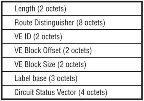
The VPLS NLRI with AFI (25) and VPLS SAFI (65) used for Auto-Discovery and Signaling of VPLS services is extended for the VPWS NLRI to include a Circuit Status Vector (CSV) encoded as a TLV. The type field of this TLV is 1 and the value field uses a bit-vector where each bit indicates the status of the PVC associated with the corresponding label in the label-block. For VPWS signaling, SR-OS always signals a label block size of 1, so only the high order bit is used. When set to 0, it indicates that the local attachment circuit and pseudowire to the remote PE is up, while a value of 1 indicates that either or both of them are down. The use of the remaining fields is as described in Chapter 3.
The Encapsulation Type field of the Layer-2 Information Extended Community (Figure 3-2) is also changed for the purpose of VPWS to allow for Ethernet VLAN (value 4) and Ethernet Raw (value 5).
Figure 4-1 VPWS NLRI Including Circuit Status Vector
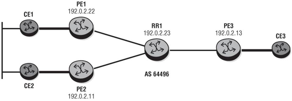
To illustrate the use of BGP VPWS, I'll use the logical topology in Figure 4-2 and illustrate a single homed and dual-homed scenario. First I'll look at the simplest scenario of a non-redundant single-homed pseudowire between PE1 and PE3. Then I'll then look at two examples of a multi-homed pseudowire between PE1/PE2 (representing a multi-homed site) and PE3; first using a single pseudowire model, and then using an active/standby pseudowire model.
Figure 4-2 BGP VPWS Test Topology
If PE routers have not already been configured to support the L2VPN Address Family it must be added to allow for mutual exchange of L2VPN NLRI. As previously discussed, if this Address Family is being added, it must be negotiated as a capability in an OPEN message and therefore triggers a NOTIFICATION/OPEN exchange.
Output 4-1: Addition of L2VPN Address Family
router
bgp
group "IBGP"
family l2vpn
peer-as 64496
neighbor …
Single-Homed VPWS
Output 4-2 shows the basic provisioning requirement for a single-homed BGP VPWS as configured at PE3. As with a BGP VPLS, BGP VPWS requires that a pw-template is created to define the characteristics of the pseudowire. This pw-template is then referenced in the bgp node of the epipe service to dynamically create a pseudowire with those characteristics. The bgp node also provides the context for configuration of route-distinguisher and route-target values. These are signaled in the VPWS NLRI and Extended Community attributes respectively.
The bgp-vpws node provides the configuration context for the ve-name, ve-id, and remote-ve-name. The ve-name is a locally significant name for the epipe service, while the ve-id is signaled as part of the VPWS NLRI. When a PE receives a VPWS NLRI to establish a BGP VPWS service, theve-id in the NLRI field is validated against the ve-id in the remote-ve-name context and must match before the VPWS becomes operational.
Debug 4-1 shows the VPWS NLRI received at PE1 from PE3 when the epipe service has been enabled. The NLRI is indicated as a VPWS NLRI by the presence of the CSV sub-TLV. The VBS is always set to a value of 1 for BGP VPWS, and the VBO is set to the remote ve-id configured in the bgp-vpws node of the advertising router. With a VBS of 1, the advertised label-base actually represents the label value that will be used for this service.
Output 4-2: Single-Homed VPWS Configuration at PE3
service
pw-template 700 create
vc-type vlan
exit
epipe 700 customer 20 create
bgp
route-distinguisher 64496:700
route-target export target:64496:700 import
target:64496:700
pw-template-binding 700
exit
exit
bgp-vpws
ve-name "PE-3"
ve-id 13
exit
remote-ve-name "PE-1"
ve-id 22
exit
no shutdown
exit
sap 1/1/3:700.* create
exit
no shutdown
Debug 4-1: VPWS NLRI received from PE3
13 2013/07/15 12:42:26.67 UTC MINOR: DEBUG #2001 Base Peer 1: 192.0.2.23
"Peer 1: 192.0.2.23: UPDATE
Peer 1: 192.0.2.23 - Received BGP UPDATE:
Withdrawn Length = 0
Total Path Attr Length = 90
Flag: 0x90 Type: 14 Len: 32 Multiprotocol Reachable NLRI:
Address Family L2VPN
NextHop len 4 NextHop 192.0.2.13
[VPLS/VPWS] veid: 13, vbo: 22, vbs: 1, label-base: 262107, RD 64496:700, csv: 0x0
Flag: 0x40 Type: 1 Len: 1 Origin: 0
Flag: 0x40 Type: 2 Len: 0 AS Path:
Flag: 0x80 Type: 4 Len: 4 MED: 0
Flag: 0x40 Type: 5 Len: 4 Local Preference: 100
Flag: 0x80 Type: 9 Len: 4 Originator ID: 192.0.2.13
Flag: 0x80 Type: 10 Len: 4 Cluster ID:
192.0.2.23
Flag: 0xc0 Type: 16 Len: 16 Extended Community:
target:64496:700
l2-vpn/vrf-imp:Encap=4: Flags=none: MTU=1514: PREF=0
"

A dynamically created SDP is not signaled until a PE router has received a valid VPWS NLRI. When a VPWS is first enabled (and no NLRI has been exchanged), the PE router initiating the VPWS NLRI does not have an operationally up spoke-SDP. Therefore the first UPDATE message may contain a CSV sub-TLV set to 1 (0x80). When the same PE router subsequently receives a VPWS NLRI from its pseudowire peer, it sources a second UPDATE message with CSV sub-TLV set to 0. Typically this first UPDATE message with CSV set to 1 is sourced when the bgp-vpws node is placed in a no shutdown state.
To validate the integrity of the VPWS, aside from checking for the presence of L2-VPN BGP routes in the RIB-IN (using the show router bgp routes l2-vpn command) you can check the service integrity by verifying the service-level L2-route-table for valid VPWS NLRI together with the associated dynamically created BGP-signaled SDPs as shown in Output 4-3 (taken from PE1), and/or by showing the service-level base information as shown in Output 4-4.
Output 4-3: PE1 Service-Level L2-Route-Table for BGP-VPWS Entries
*A:PE1# show service id 700 l2-route-table bgp-vpws
==============================================================
Services: L2 Bgp-Vpws Route Information - Service 700
==============================================================
L2-Routes (RD) Next Hop Ve-Id Sdp Bind Id
--------------------------------------------------------------
*64496:700 192.0.2.13 13 17407:4294967292
--------------------------------------------------------------
No. of L2 Bgp-Vpws Route Entries: 1
==============================================================
Output 4-4: PE1 Service-Level Base Information
*A:PE1# show service id 700 base
=======================================================================
Service Basic Information
=======================================================================
Service Id : 700 Vpn Id : 0
Service Type : Epipe
Name : BGP Pseudowire
Description : (Not Specified)
Customer Id : 20 Creation Origin : manual
Last Status Change: 07/15/2013 12:38:12
Last Mgmt Change : 07/15/2013 09:59:54
Admin State : Up Oper State : Up
MTU : 1514
Vc Switching : False
SAP Count : 1 SDP Bind Count : 1
Per Svc Hashing : Disabled
Force QTag Fwd : Disabled
-----------------------------------------------------------------------
Service Access & Destination Points
-----------------------------------------------------------------------
Identifier Type AdmMTU OprMTU Adm Opr
-----------------------------------------------------------------------
sap:1/1/3:700.* qinq 1522 1522 Up Up
sdp:17407:4294967292 SB(192.0.2.13) BgpVpws 0 9186 Up Up
========================================================================
When using BGP VPWS with a dual-homed site using active/standby pseudowire, the system automatically creates an “endpoint” object to manage the active/standby status and put the appropriate pseudowire into a forwarding state. For ease of implementation, the system also automatically creates an endpoint named _tmnx_BgpVpws-<service id> even if the VPWS is single-homed. This can be seen for the example VPWS service in Output 4-5. However, for a single-homed VPWS this endpoint object is irrelevant and can be ignored.
Output 4-5: Automatic Endpoint Creation
*A:PE1# show service id 700 endpoint
========================================================================
Service 700 endpoints
========================================================================
Endpoint name : _tmnx_BgpVpws-700
Description : Automatically created BGP-VPWS endpoint
Creation Origin : bgpVpws
Revert time : 0
Act Hold Delay : 0
Standby Signaling Master : false
Standby Signaling Slave : false
Tx Active (SDP) : 17404:4294967288
Tx Active Up Time : 0d 00:05:11
Revert Time Count Down : N/A
Tx Active Change Count : 3
Last Tx Active Change : 07/15/2013 12:41:29
------------------------------------------------------------------------
Members
------------------------------------------------------------------------
Spoke-sdp: 17404:4294967288 Prec:4 Oper Status: Up
========================================================================
========================================================================
To verify the use of the CSV field for signaling of VPWS integrity, I'll simulate a failure of the attachment circuit at PE3. Recall that the one-octet CSV field uses a bit-vector where each bit indicates the status of the PVC associated with the corresponding label in the label-block. As SR-OS always signals a label block size of 1 only the high order bit is used, and this can be seen in Debug 4-2 which shows the CSV field set to a hex value of 0x80 (decimal 128) to reflect the attachment circuit failure.
Debug 4-2: Attachment Circuit Failure Signaled with CSV Field
14 2013/07/15 12:45:56.67 UTC MINOR: DEBUG #2001 Base Peer 1: 192.0.2.23
"Peer 1: 192.0.2.23: UPDATE
Peer 1: 192.0.2.23 - Received BGP UPDATE:
Withdrawn Length = 0
Total Path Attr Length = 90
Flag: 0x90 Type: 14 Len: 32 Multiprotocol Reachable NLRI:
Address Family L2VPN
NextHop len 4 NextHop 192.0.2.13
[VPLS/VPWS] veid: 13, vbo: 22, vbs: 1, label-base: 262107, RD 64496:700, csv: 0x80
Flag: 0x40 Type: 1 Len: 1 Origin: 0
Flag: 0x40 Type: 2 Len: 0 AS Path:
Flag: 0x80 Type: 4 Len: 4 MED: 0
Flag: 0x40 Type: 5 Len: 4 Local Preference: 100
Flag: 0x80 Type: 9 Len: 4 Originator ID: 192.0.2.13
Flag: 0x80 Type: 10 Len: 4 Cluster ID:
192.0.2.23
Flag: 0xc0 Type: 16 Len: 16 Extended Community:
target:64496:700
l2-vpn/vrf-imp:Encap=4: Flags=D: MTU=1514: PREF=0
"
The preceding example illustrates the requirements of a BGP VPWS using a dynamically created SDP using any LDP transport LSP that is available. If there is a requirement to reference an explicitly-defined SDP (for example, to use an RSVP transport LSP) for the BGP VPWS, the pw-template must be configured with the creation-time attribute use-provisioned-sdp. When a valid VPWS NLRI is received from a peer, the system thereafter looks for explicitly-defined SDPs with a corresponding far-end IP address. Explicitly-defined SDPs, however, must be configured for BGP signaling.
Multi-Homed VPWS
As previously described, SR-OS provides the capability to support redundant access with BGP Multi-Homing using either a single pseudowire to the DF or by signaling two pseudowires to the DF and non-DF in an active/standby arrangement managed by an endpoint object. This sub-section discusses both methods in turn using PE1 and PE2 as the multi-homed site and PE3 as a single-homed site.
Single-Homed Pseudowire
Output 4-6 shows the configuration for the multi-homed VPWS at PE1. The notable difference from the single-homed VPWS scenario previously described is the addition of the site node. The concept of sites is familiar to readers of Chapter 3, and the command syntax does not vary between VPLS and VPWS. The site node contains the site-id representing the MH-ID signalled in the MH NLRI and must be common across the PEs supporting a multi-homed site. The site-preference field indicates a level of preference in the DF election; a higher value is preferred. In this example PE1 has a preference of 100 while PE2 has a preference of 50. To indicate a level of preference to transit BGP speakers (who may not interpret this service-level multi-homing preference value) the value that is configured in the site-preference field is also automatically populated into the LOCAL_PREF attribute, and the system ignores attempts to modify the LOCAL_PREF attribute through policy. The site node also contains local SAPs that that are placed in forwarding or non-forwarding state depending on the outcome of the DF election.
The boot-timer defines how long the system waits after a node reboot before executing the DF election algorithm and allows for BGP sessions to be established and NLRI to be exchanged before executing the algorithm. The site-activation-timer defines how long the system keeps the local sites in standby status waiting for BGP UPDATEs from remote PEs before running the DF election algorithm.
Each of the PEs supporting the multi-homed site must be provisioned with a unique Route Distinguisher, which allows the VPWS NLRI from different VPLS PEs to be distinct even if the advertisements have the same VE-ID, which as described previously is a requirement for multi-homed VPWS.
Output 4-6: PE1 Multi-Homed VPWS Configuration
service
pw-template 700 create
vc-type vlan
exit
epipe 700 customer 20 create
bgp
route-distinguisher 64496:700
route-target export target:64496:700 import
target:64496:700
pw-template-binding 700
exit
exit
bgp-vpws
ve-name "PE-1"
ve-id 22
exit
remote-ve-name "PE-3"
ve-id 13
exit
no shutdown
exit
site "DUAL-HOME" create
site-id 700
sap 1/1/3:700.*
boot-timer 360
site-activation-timer 30
site-preference 100
no shutdown
exit
sap 1/1/3:700.* create
exit
no shutdown
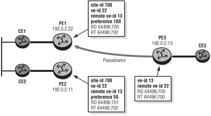
As described during the single-homed BGP VPWS setup, when a PE receives a VPWS NLRI to establish a BGP VPWS service, the ve-id in the NLRI field is validated against the ve-id in the remote-ve-name context and must match before the VPWS becomes operational. This constitutes one of the main differences in provisioning for the single pseudowire method and the active/standby pseudowire method. In the single pseudowire method, there is a single remote ve-id configured at PE3, so the ve-ids configured at the PE1 and PE2 must be the same so that PE3 only sees a single ve-id and validates it against its configured remote ve-id. For the active/standby pseudowire method, two remote ve-ids are configured at PE3, so each of the ve-ids configured at PE1 and PE2 are different and correspond to the remote ve-ids configured at PE3. Note, however, that the ve-name has local significance only, and can be the same or different at PE1 and PE2.
Figure 4-3 VE-IDs using the Single-Pseudowire Method
Debug 4-3 shows the VPWS NLRI advertised by PE1 as the multi-homed VPWS is enabled. The preference in the L2 Information Extended Community reflects the configured site-preference and in turn is reflected in the LOCAL_PREF attribute. This preference influences the outcome of the DF election process and therefore determines the destination to which PE3 signals its pseudowire. In short, PE3's decision on which PE it signals its pseudowire to is made on the basis of the VPWS NLRI—it doesn't use the MH NLRI at all because the information required for PE3 to run its DF election is in the VPWS UPDATE and should be the same in both the VPWS and MH UPDATEs. This is followed in Debug 4-4 by an MH NLRI received at PE2 and also advertised by PE1 indicating that PE1 (192.0.2.22) is the DF. Of course, because the VPWS and MH NLRI have the same Route-Target values, it follows that both PE2 and PE3 would have received both UPDATE messages. However, I've illustrated them this way to make two points:
· PE3 only needs to see the VPWS NLRI to determine the outcome of the DF election and therefore to know where to signal its pseudowire.
· The MH NLRI is only relevant to the Multi-Homed PEs.
Debug 4-3: PE1's VPWS NLRI received at PE3
84 2013/07/15 13:11:21.67 UTC MINOR: DEBUG #2001 Base Peer 1: 192.0.2.23
"Peer 1: 192.0.2.23: UPDATE
Peer 1: 192.0.2.23 - Received BGP UPDATE:
Withdrawn Length = 0
Total Path Attr Length = 90
Flag: 0x90 Type: 14 Len: 32 Multiprotocol Reachable NLRI:
Address Family L2VPN
NextHop len 4 NextHop 192.0.2.22
[VPLS/VPWS] veid: 22, vbo: 13, vbs: 1, label-base: 131055, RD
64496:700, csv: 0x0
Flag: 0x40 Type: 1 Len: 1 Origin: 0
Flag: 0x40 Type: 2 Len: 0 AS Path:
Flag: 0x80 Type: 4 Len: 4 MED: 0
Flag: 0x40 Type: 5 Len: 4 Local Preference: 100
Flag: 0x80 Type: 9 Len: 4 Originator ID: 192.0.2.22
Flag: 0x80 Type: 10 Len: 4 Cluster ID:
192.0.2.23
Flag: 0xc0 Type: 16 Len: 16 Extended Community:
target:64496:700
l2-vpn/vrf-imp:Encap=4: Flags=none: MTU=1514: PREF=100
"
Debug 4-4: PE1's MH NLRI received at PE2
11 2013/07/15 13:11:21.67 UTC MINOR: DEBUG #2001 Base Peer 1: 192.0.2.23
"Peer 1: 192.0.2.23: UPDATE
Peer 1: 192.0.2.23 - Received BGP UPDATE:
Withdrawn Length = 0
Total Path Attr Length = 86
Flag: 0x90 Type: 14 Len: 28 Multiprotocol Reachable NLRI:
Address Family L2VPN
NextHop len 4 NextHop 192.0.2.22
[MH] site-id: 700, RD 64496:700
Flag: 0x40 Type: 1 Len: 1 Origin: 0
Flag: 0x40 Type: 2 Len: 0 AS Path:
Flag: 0x80 Type: 4 Len: 4 MED: 0
Flag: 0x40 Type: 5 Len: 4 Local Preference: 100
Flag: 0x80 Type: 9 Len: 4 Originator ID: 192.0.2.22
Flag: 0x80 Type: 10 Len: 4 Cluster ID:
192.0.2.23
Flag: 0xc0 Type: 16 Len: 16 Extended Community:
target:64496:700
l2-vpn/vrf-imp:Encap=19: Flags=-DF: MTU=0: PREF=100
"
Using the service-level L2-route-table verification shown in Output 4-7, you can verify the presence of VPWS NLRI from the DF together with the associated dynamically created SDP binding. Note that the VPWS NLRI from the non-DF remains in the RIB-IN and is not shown in this output. In addition, note that PE1 (192.0.2.22) is the DF for Site-ID 700 (DF bits set) while PE2 (192.0.2.11) is the non-DF. This means PE2 must place all attachment circuits associated with Site-ID 700 into a non-forwarding state. Output 4-8 shows this; the SAP is put into an operationally down state with the flag StandbyForMHProtocol.
Output 4-7: Service-Level L2-Route-Table at PE3
*A:PE3# show service id 700 l2-route-table multi-homing bgp-vpws
=======================================================================
Services: L2 Multi-Homing Route Information - Summary
=======================================================================
Svc Id L2-Routes (RD-Prefix) Next Hop SiteId State DF
-----------------------------------------------------------------------
700 64496:700 192.0.2.22 700 up(0) set
700 64496:701 192.0.2.11 700 up(0) clear
-----------------------------------------------------------------------
No. of L2 Multi-Homing Route Entries: 2
=======================================================================
==============================================================
Services: L2 Bgp-Vpws Route Information - Service 700
==============================================================
L2-Routes (RD) Next Hop Ve-Id Sdp Bind Id
--------------------------------------------------------------
*64496:700 128.8.72.22 22 17403:4294967276
--------------------------------------------------------------
No. of L2 Bgp-Vpws Route Entries: 1
==============================================================
Output 4-8: PE2 Attachment Circuit in Non-Forwarding State
*A:PE2# show service id 700 sap 1/1/3:700.*
=======================================================================
Service Access Points(SAP)
=======================================================================
Service Id : 700
SAP : 1/1/3:700.* Encap : qinq
QinQ Dot1p : Default
Description : (Not Specified)
Admin State : Up Oper State : Down
Flags : StandByForMHProtocol
Multi Svc Site : None
Last Status Change : 07/15/2013 13:11:16
Last Mgmt Change : 07/15/2013 13:01:45
=======================================================================
To verify the failover capabilities for BGP multi-homing in VPWS I'll once again simulate a failure on the attachment circuit at the current DF, PE1. As with BGP VPLS, the reconvergence times largely depend on BGP UPDATE propagation times so you should consider use of the rapid-update l2-vpn command described in Chapter 3 if fast reconvergence times are a requirement.
When the attachment circuit has failed at PE1, it sources two UPDATE messages:
· A VPWS NLRI with the CSV field set (0x80) and the D bit of the Layer-2 Information Extended Community flags field set to reflect the attachment circuit failure
· An MH NLRI with the D bit set and the F bit clear because it can no longer function as DF for the multi-homed site
Debug 4-5 shows both UDPATEs.
Debug 4-5: PE2 Attachment Circuit Failure
89 2013/07/15 13:18:21.67 UTC MINOR: DEBUG #2001 Base Peer 1: 192.0.2.23
"Peer 1: 192.0.2.23: UPDATE
Peer 1: 192.0.2.23 - Received BGP UPDATE:
Withdrawn Length = 0
Total Path Attr Length = 90
Flag: 0x90 Type: 14 Len: 32 Multiprotocol Reachable NLRI:
Address Family L2VPN
NextHop len 4 NextHop 192.0.2.22
[VPLS/VPWS] veid: 22, vbo: 13, vbs: 1, label-base: 131055, RD 64496:700, c
sv: 0x80
Flag: 0x40 Type: 1 Len: 1 Origin: 0
Flag: 0x40 Type: 2 Len: 0 AS Path:
Flag: 0x80 Type: 4 Len: 4 MED: 0
Flag: 0x40 Type: 5 Len: 4 Local Preference: 0
Flag: 0x80 Type: 9 Len: 4 Originator ID: 192.0.2.22
Flag: 0x80 Type: 10 Len: 4 Cluster ID:
192.0.2.23
Flag: 0xc0 Type: 16 Len: 16 Extended Community:
target:64496:700
l2-vpn/vrf-imp:Encap=4: Flags=D: MTU=1514: PREF=100
"
88 2013/07/15 13:18:21.67 UTC MINOR: DEBUG #2001 Base Peer 1: 192.0.2.23
"Peer 1: 192.0.2.23: UPDATE
Peer 1: 192.0.2.23 - Received BGP UPDATE:
Withdrawn Length = 0
Total Path Attr Length = 86
Flag: 0x90 Type: 14 Len: 28 Multiprotocol Reachable NLRI:
Address Family L2VPN
NextHop len 4 NextHop 192.0.2.22
[MH] site-id: 700, RD 64496:700
Flag: 0x40 Type: 1 Len: 1 Origin: 0
Flag: 0x40 Type: 2 Len: 0 AS Path:
Flag: 0x80 Type: 4 Len: 4 MED: 0
Flag: 0x40 Type: 5 Len: 4 Local Preference: 0
Flag: 0x80 Type: 9 Len: 4 Originator ID: 192.0.2.22
Flag: 0x80 Type: 10 Len: 4 Cluster ID:
192.0.2.23
Flag: 0xc0 Type: 16 Len: 16 Extended Community:
target:64496:700
l2-vpn/vrf-imp:Encap=19: Flags=D: MTU=0: PREF=100
"
The UPDATE from PE1 indicating a transition to non-DF (attachment circuit down) means that PE2, which forms part of the same Site-ID, must transition to DF. As a result, PE2 sources an MH NLRI with the DF bits of flags field in the Layer-2 Information community set as shown in Debug 4-6.
Debug 4-6: Transition to DF at PE1
87 2013/07/15 13:18:21.66 UTC MINOR: DEBUG #2001 Base Peer 1: 192.0.2.23
"Peer 1: 192.0.2.23: UPDATE
Peer 1: 192.0.2.23 - Received BGP UPDATE:
Withdrawn Length = 0
Total Path Attr Length = 86
Flag: 0x90 Type: 14 Len: 28 Multiprotocol Reachable NLRI:
Address Family L2VPN
NextHop len 4 NextHop 192.0.2.11
[MH] site-id: 700, RD 64496:701
Flag: 0x40 Type: 1 Len: 1 Origin: 0
Flag: 0x40 Type: 2 Len: 0 AS Path:
Flag: 0x80 Type: 4 Len: 4 MED: 0
Flag: 0x40 Type: 5 Len: 4 Local Preference: 50
Flag: 0x80 Type: 9 Len: 4 Originator ID: 192.0.2.11
Flag: 0x80 Type: 10 Len: 4 Cluster ID:
192.0.2.23
Flag: 0xc0 Type: 16 Len: 16 Extended Community:
target:64496:700
l2-vpn/vrf-imp:Encap=19: Flags=-DF: MTU=0: PREF=50
"
Checking the service level L2-route-table again at PE3, you can verify that the multi-homing information shows that the DF bits from PE2 are set, while PE1 is signaling the F bit as clear, but the D bit is set to indicate that the attachment circuit is down. In addition, the VPWS route information displays the VPWS NLRI from PE2 with the associated binding. As with VPLS Multi-Homing, the failover mechanism is revertive, meaning that when the attachment circuit at PE2 recovers it again becomes DF.
Output 4-9: Service-Level L2-Route-Table at PE3
*A:PE3# show service id 700 l2-route-table multi-homing bgp-vpws
=======================================================================
Services: L2 Multi-Homing Route Information - Summary
=======================================================================
Svc Id L2-Routes (RD-Prefix) Next Hop SiteId State DF
-----------------------------------------------------------------------
700 64496:700 192.0.2.22 700 dn(1) clear
700 64496:701 192.0.2.11 700 up(0) set
-----------------------------------------------------------------------
No. of L2 Multi-Homing Route Entries: 2
=======================================================================
==============================================================
Services: L2 Bgp-Vpws Route Information - Service 700
==============================================================
L2-Routes (RD) Next Hop Ve-Id Sdp Bind Id
--------------------------------------------------------------
*64496:701 192.0.2.11 22 17403:4294967275
--------------------------------------------------------------
No. of L2 Bgp-Vpws Route Entries: 1
==============================================================
Active/Standby Pseudowire
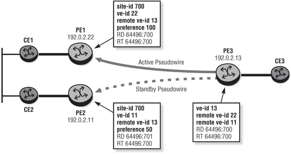
As indicated in the previous sub-section, the notable difference in provisioning for the active/standby pseudowire method is that two remote ve-ids are configured at PE3 instead of one ve-id used in the single pseudowire scenario. As a result, the ve-ids configured at PE1 and PE2 are different and correspond to the two remote ve-ids configured at PE3.
Aside from the different ve-ids, there is no other configuration change at PE1 and PE2 for the active/standby pseudowire method. At PE3 a second remote-ve-name is configured. It provides the context to configure the second ve-id.
Figure 4-4 VE-IDs for the Active/Standby Pseudowire Method
Output 4-10: Active/Standby Pseudowire Configuration at PE3
service
epipe 700 customer 20 create
bgp
route-distinguisher 701:700
route-target export target:701:700 import target:701:700
pw-template-binding 700
exit
exit
bgp-vpws
ve-name "PE-3"
ve-id 13
exit
remote-ve-name "PE-1"
ve-id 22
exit
remote-ve-name "PE-2"
ve-id 11
exit
no shutdown
exit
sap 1/1/3:700.* create
exit
no shutdown
All VPWS and Multi-Homing UPDATE signaling used to establish the pseudo-wire and reconverge upon failure (DF transition) is the same as the single pseudowire method. The main difference is that both the active and standby pseudowires are presignaled and the forwarding state is controlled by a system-created endpoint. Output 4-11 shows this with the endpoint name _tmnx_BgpVpws-700 and description “Automatically created BGP-VPWS endpoint.” The active SDP is 17402:4294967271, which is the pseudowire to PE1. Confirmation that PE1 is the DF is given by the L2-Route-Table shown in Output 4-12.
Output 4-11: Active/Standby Pseudowire with Dynamic Endpoint
*A:PE3# show service id 700 endpoint
=======================================================================
Service 700 endpoints
=======================================================================
Endpoint name : _tmnx_BgpVpws-700
Description : Automatically created BGP-VPWS endpoint
Creation Origin : bgpVpws
Revert time : 0
Act Hold Delay : 0
Standby Signaling Master : false
Standby Signaling Slave : false
Tx Active (SDP) : 17402:4294967271
Tx Active Up Time : 0d 00:03:27
Revert Time Count Down : N/A
Tx Active Change Count : 3
Last Tx Active Change : 07/15/2013 14:41:25
-----------------------------------------------------------------------
Members
-----------------------------------------------------------------------
Spoke-sdp: 17402:4294967271 Prec:4 Oper Status: Up
Spoke-sdp: 17403:4294967273 Prec:4 Oper Status: Up
=======================================================================
=======================================================================
Output 4-12: L2-Route-Table at PE3
*A:PE3# show service id 700 l2-route-table multi-homing bgp-vpws
=======================================================================
Services: L2 Multi-Homing Route Information - Summary
=======================================================================
Svc Id L2-Routes (RD-Prefix) Next Hop SiteId State DF
-----------------------------------------------------------------------
700 64496:700 192.0.2.22 700 up(0) set
700 64496:701 192.0.2.11 700 up(0) clear
-----------------------------------------------------------------------
No. of L2 Multi-Homing Route Entries: 2
=======================================================================
==============================================================
Services: L2 Bgp-Vpws Route Information - Service 700
==============================================================
L2-Routes (RD) Next Hop Ve-Id Sdp Bind Id
--------------------------------------------------------------
*64496:701 192.0.2.11 11 17403:4294967273
*64496:700 192.0.2.22 22 17402:4294967271
--------------------------------------------------------------
No. of L2 Bgp-Vpws Route Entries: 2
==============================================================
In summary, both single pseudowire and active/standby pseudowire use common UPDATE signaling to set up and maintain the pseudowire, but the significant difference is the presence of a presignaled standby pseudowire in the active/standby pseudowire model. This can reduce reconvergence times upon DF transition. Both mechanisms are revertive upon failure restoration, and this is non-configurable.
Dynamic Multi-Segment Pseudowire
A multi-segment pseudowire (MS-PW) (draft-ietf-pwe3-dynamic-ms-pw) is a set of two or more contiguous pseudowire segments that behave and function as a single point-to-point pseudowire. MS-PWs are useful when, for example, you need to extend a pseudowire across two Autonomous Systems, or when you have a high level of concentration of pseudowires and Targeted-LDP sessions at a site (such as a Mobile Switch Site aggregating Base Stations in a Radio Access Network) that would benefit from some form of hierarchy.
Each end of an MS-PW terminates on a Terminating-PE (T-PE). The T-PE is where the customer-facing attachment circuits are connected, and so the T-PEs are present in the first and last segments of an MS-PW. The MS-PW is formed of multiple segments, and Switching-PEs are responsible for switching the control and data planes of the preceding and succeeding pseudowire segments of an MS-PW. From a control plane perspective, the S-PEs must have targeted LDP sessions to one or more T-PEs and/or one or more S-PEs (unless the pseudowire is statically configured). At a data-plane level, the S-PE simply switches PDUs between segments based on an MPLS label-swap operation at pseudowire label level. You can have any number of S-PEs forming a MS-PW, and this is limited only by the TTL imposed on the pseudowire label.
The MS-PW can be established using static configuration, LDP signaling using FEC 128 (PWid FEC Element), or LDP signaling using FEC 129 (Generalized ID FEC Element). The first method obviously requires no signaling, while the second method requires manual provisioning of the S-PE. For LDP signaling using FEC 128, the T-PE must be provisioned so that the pseudowire segment (SAP-to-SDP) is forwarded to a known and provisioned S-PE, and each S-PE must be provisioned so that each SDP-to-SDP pseudowire segment is forwarded to a known and provisioned S-PE or T-PE. The third method, using LDP FEC 129, allows for dynamic placement of MS-PWs, whereby T-PEs can automatically learn the whereabouts of S-PEs, and no provisioning is required at the S-PE to switch the pseudowire segments constituting a MS-PW.
A pseudowire essentially connects two forwarders. To allow the forwarder at one end of the pseudowire to identify the forwarder at the other end, LDP signaling with FEC 129 uses an Attachment Group Identifier (AGI) and Attachment Individual Identifiers (AII). The AGI essentially represents a VPN-id (or VLAN identifier) and is used for BGP VPLS but is not used in MS-PW signaling. As a result it is set to zero. The AII consists of a local or Source AII (SAII) and a remote or Target AII (TAII) and can have two different formats. AII Type 1 is made up of a fixed 32-bit value unique on the local PE and is used by BGP-AD for VPLS. AII Type 2 is used by MS-PW and is constructed by a concatenation of <Global ID:Prefix:AC ID>.
Figure 4-5 FEC 129 Encoding with AII Type 2
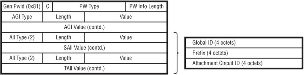
The Global ID field is typically constructed from the Autonomous System number of the PE, the prefix from the node system address, and the Attachment Circuit ID or local pseudowire endpoint identifier. The combination of all three identifiers derives a 96-bit AII value that is globally unique.
The combination of the AGI, SAII, and TAII allows you to uniquely identify a given pseudowire, but the local PE must learn a route toward the remote TAII before the FEC 129 Element can be signaled in LDP. In SR-OS, a local PE can learn pseudowire routing information using three methods:
· Static-routing
· Multi-Protocol BGP
· Explicit paths (where the latter can be configured independently of both the former)
Because this book is about BGP, I'll explain only the use of Multi-Protocol BGP.
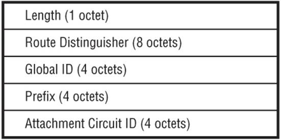
Pseudowire Routing information is advertised in Multi-Protocol BGP using AFI 25 (L2VPN) SAFI 6 (MS-PW routing) and maps the fields Global ID, Prefix, and AC ID from the FEC 129 AII Type 2 fields directly into the NLRI. However, because the source T-PE knows in advance (through configuration) the Source and Target AC ID to use, only the Global ID and Prefix (plus prefix length) must be advertised. The use of AII Type 2-based addressing schemes allows for varying levels of AII summarization. The minimum length of the NLRI is 12 bytes indicating only the presence of an RD and Global ID, while the maximum length is 20 bytes.
Figure 4-6 MS-PW NLRI
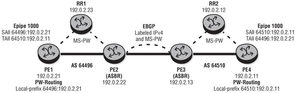
To illustrate the use of MS-PW and pseudowire routing information, I'll use the topology shown in Figure 4-7. PE1, PE2, and RR1 form part of AS 64496. In this figure, PE1 and PE2 are IBGP clients of RR1 and are configured to exchange a number of address families including the MS-PW NLRI. Similarly PE3, PE4, and RR2 form part of AS 64510; PE3 and PE4 are IBGP clients of RR2 and are configured to exchange MS-PW NLRI. PE2 and PE3 are both functioning as ASBRs and are EBGP-peered for address families MS-PW and labeled IPv4. They exchange system addresses in labeled IPv4 to establish an LDP session for inter-domain pseudowire signaling and to create a BGP tunnel for the purpose of providing a transport layer LSP for those inter-domain pseudowires.
Figure 4-7 MS-PW and Pseudowire Routing Test Topology
Parameters that control the distribution of pseudowire routing information into BGP are entered in the pw-routing context as shown in the example from PE1 in Output 4-13. Every router participating in pseudowire routing (regardless of whether the role is S-PE or T-PE) is first configured with an spe-address in the form <global-id:prefix>. The spe-address populates the Switching Point TLV in LDP mapping messages and identifies a given S-PE in pseudowire status notification TLVs. In this example, the ASN is used for the global-id and the system address is used for the prefix.
After the spe-address has been configured, one or more prefixes (to a maximum of 16) are configured using the local-prefix command. These prefixes represent T-PEs in the pseudowire routing domain and are again entered in the format <global-id:prefix>. To advertise the prefix into BGP, the local-prefix node then provides the ability to specify a route-distinguisher and optional standard community value using the advertise-bgp command.
Output 4-13: PW-Routing Configuration
service
pw-routing
spe-address 64496:192.0.2.21
local-prefix 64496:192.0.2.13 create
advertise-bgp route-distinguisher 64496:1000 community
64496:1000
exit
exit
To advertise pseudowire routing information, you must have an export policy that explicitly permits advertisement of MS-PW NLRI. In addition, the MS-PW Address Family must be specified as an Address Family so its use can be negotiated with peers. If this Address Family is being added to a set of existing Address Families, it must be negotiated as a capability in an OPEN message and therefore triggers a NOTIFICATION/OPEN exchange with the associated peers.
Output 4-14: MS-PW Routing Policy
router
policy-options
policy-statement "export-ms-pw"
entry 10
from
family ms-pw
exit
action accept
exit
exit
default-action accept
exit
exit
bgp
group "IBGP"
family vpn-ipv4 l2-vpn ms-pw
peer-as 64496
neighbor 192.0.2.23
export "export-ms-pw"
exit
exit
no shutdown
exit
When the pseudowire routing information has been completed, the MS-PW NLRI is exchanged. Debug 4-7 shows the MS-PW generated by PE4 as received at PE1 with a Next-Hop of the AS 64496 ASBR, PE2. As previously discussed, in the MS-PW NLRI, only the global-id and prefix are advertised while the AC ID is set to zero.
Debug 4-7: MS-PW NLRI Received at PE1
3 2013/06/19 15:18:37.05 UTC MINOR: DEBUG #2001 Base Peer 1: 192.0.2.23
"Peer 1: 192.0.2.23: UPDATE
Peer 1: 192.0.2.23 - Received BGP UPDATE:
Withdrawn Length = 0
Total Path Attr Length = 71
Flag: 0x90 Type: 14 Len: 26 Multiprotocol Reachable NLRI:
Address Family MSPW
NextHop len 4 NextHop 192.0.2.22
[MSPW] rd: 64510:1000, global-id 64510, prefix 192.0.2.11, ac-id 0, preflen
128
Flag: 0x40 Type: 1 Len: 1 Origin: 2
Flag: 0x40 Type: 2 Len: 6 AS Path:
Type: 2 Len: 1 < 64510 >
Flag: 0x40 Type: 5 Len: 4 Local Preference: 100
Flag: 0xc0 Type: 8 Len: 4 Community:
64510:1000
Flag: 0x80 Type: 9 Len: 4 Originator ID: 192.0.2.22
Flag: 0x80 Type: 10 Len: 4 Cluster ID:
192.0.2.23
"
The received and valid MS-PW NLRI populate a pseudowire routing table that is used by T-PEs and S-PEs to determine the Next Signaling Hop (NSH) for an LDP mapping message. When targeted LDP signals the LDP label mapping for a given TAII, it first checks if there is an explicit path configured for that pseudowire. If not, it performs a longest-prefix lookup of the TAII in the pseudowire routing table to determine the NSH. Output 4-15 shows an example output of the pseudowire routing table at PE1. In this example, the first two entries are local while the third entry is the MS-PW NLRI signaled by PE4 in AS 64510 with a NSH of PE2. The entries are denoted as 64 bits in length, indicating the presence of global-id and prefix only.
Output 4-15: PW-Routing Route-Table
*A:PE1# show service pw-routing route-table
=======================================================================
Service PW L2 Routing Information
=======================================================================
AII-Type2/Prefix-Len Next-Hop Owner Age
Route-Distinguisher Community Best
-----------------------------------------------------------------------
64496:192.0.2.22:0/64 192.0.2.21 local 00h26m41s
0:0 0:0 yes
64496:192.0.2.22:0/64 192.0.2.21 local 00h26m24s
64496:1000 64496:1000 yes
64510:192.0.2.11:0/64 192.0.2.22 bgp 00h00m56s
64510:1000 64510:1000 yes
-----------------------------------------------------------------------
Entries found: 3
=======================================================================
With the correct routing information in place, you can configure the pseudowire service. Output 4-16 shows an example of this configuration at PE1. The notable difference from a standard pseudowire configuration is the spoke-sdp-fec node. FEC 129 spoke-SDPs are configured in the spoke-sdp-fec node where the creation-time attributes fec-type and aai-type are configured for 129 and 2 respectively. The spoke-sdp-fec also has a local index value, which is the first integer following the spoke-sdp-fec keyword. Within the spoke-sdp-fec node the SAII and TAII are configured using the saii-type2 and taii-type2 commands. The values for each represent the tuple <global-id:prefix:AC ID> as previously discussed. In this example, PE1 is creating a FEC 129 pseudowire with local AC ID 1000 to PE4, which also has AC ID 1000. PE4 has a similar configuration, with the exception that the TAII and SAII values are inverse.
Output 4-16: Epipe Configuration at PE1
service
epipe 1000 customer 1 create
service-name "DYNAMIC MS-PW"
sap 1/1/4:1000 create
exit
spoke-sdp-fec 1 fec 129 aii-type 2 create
saii-type2 64496:192.0.2.21:1000
taii-type2 64510:192.0.2.11:1000
no shutdown
exit
no shutdown
exit
Spoke-sdp-fecs can be part of an endpoint or an Inter-Chassis Backup (ICB) pseudowire.
With the service configured at both PE1 and PE4, the LDP mapping messages are exchanged. Debug 4-8 shows the FEC 129 label mapping message sourced by PE2 (the S-PE) toward PE1 (the T-PE), noting the presence of the AGI set to zero as well as the SAII and TAII.
Debug 4-8: LDP Mapping Message Received at PE1
10 2013/06/19 16:28:52.61 UTC MINOR: DEBUG #2001 Base LDP
"LDP: LDP
Recv Notification packet (msgId 810) from 192.0.2.22:0
Status Code = PWStatus Non-fatal
Causing message Id = 0
Causing message type = NULL
Service FEC GENPWE3: ENET(5)
AGI = type: 1, len: 8, val: 00:00
SAII= T: 2, L: 12, Global-id: 64510, Prefix: 192.0.2.11, AcId: 1000
TAII= T: 2, L: 12, Global-id: 64496, Prefix: 192.0.2.21, AcId: 1000
Group ID = 0 cBit = 1
PW status bits = 0x0
"
Finally, you can verify that you have a working multi-segment pseudowire with a dynamically signaled spoke-SDP of type MS-PW.
Output 4-17: Verification of a working Multi-Segment Pseudowire at PE1
*A:PE1# show service id 1000 base
=======================================================================
Service Basic Information
=======================================================================
Service Id : 1000 Vpn Id : 0
Service Type : Epipe
Name : DYNAMIC MS-PW
Description : (Not Specified)
Customer Id : 1 Creation Origin : manual
Last Status Change: 06/19/2013 16:27:52
Last Mgmt Change : 06/19/2013 16:27:52
Admin State : Up Oper State : Up
MTU : 1514
Vc Switching : False
SAP Count : 1 SDP Bind Count : 1
Per Svc Hashing : Disabled
Force QTag Fwd : Disabled
-----------------------------------------------------------------------
Service Access & Destination Points
-----------------------------------------------------------------------
Identifier Type AdmMTU OprMTU Adm Opr
-----------------------------------------------------------------------
sap:1/1/4:1000 q-tag 1518 1518 Up Up
sdp:17407:4294967295 SB(192.0.2.22) MS-PW 0 9186 Up Up
=======================================================================
Although the pseudowire is dynamically signaled once the spoke-sdp-fec node is created and enabled, it requires that Targeted LDP sessions are in place between T-PEs and S-PEs in the signaling path. In the example used in this section, SDPs using LDP as a transport are configured within each AS, while an SDP using a BGP-tunnel for transport is configured between the ASBRs PE2 and PE3.