Make: More Electronics (2014)
Chapter 33. Experiment 33: Reading Rotation
Everyone is familiar with that old-school favorite, the potentiometer. In this book alone, I have used maybe twenty trimmer potentiometers in the various circuits.
In consumer electronics, it’s a different story. Your car stereo probably still has a volume-control knob, but it will turn a full 360 degrees—and keep on turning. This suggests that something other than a potentiometer may be hidden behind it.
What component has taken its place? The answer is a rotational encoder, also known as a rotary encoder, or an incremental encoder, or an electromechanical encoder (because it has mechanical contacts inside it). A selection of them is shown in Figure 33-1. Their appearance is reminiscent of potentiometers—indeed, most of them even have three terminals. But their behavior is very different.
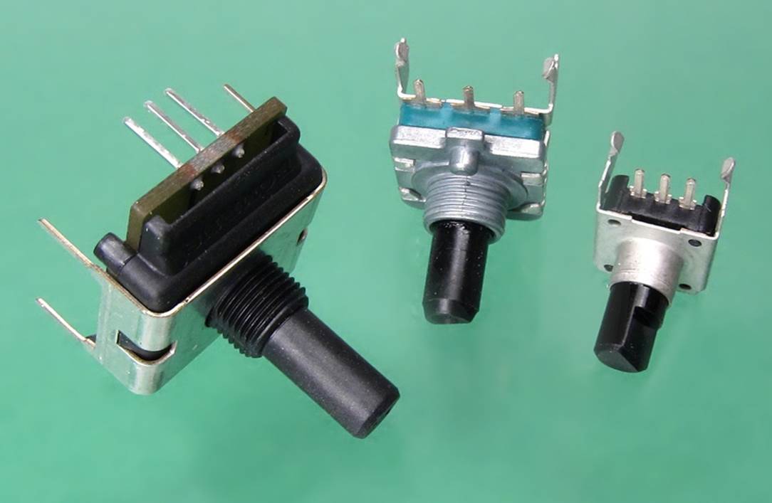
Figure 33-1. A selection of commonly used, inexpensive rotational encoders.
Defining a Rotational Encoder
First we have to distinguish clearly between different types of encoder. Obviously I’m not talking about solid-state encoder chips. We already explored them in detail, and you must have noticed that they didn’t have any knobs on them.
A rotational encoder has a shaft and at least two terminals, and generates a stream of pulses from internal contacts while its shaft is rotating. Another component (usually, a microcontroller) must interpret that stream and decide what to do in response. It can adjust the sound in an audio system, or cycle through some prompts on a screen, or perform any other task specified by its program.
Originally a rotational encoder was a high-end kind of component, often using optical methods to measure rotation very precisely (more than 100 intervals within 360 degrees). That definition has changed. Any component containing contacts that generate a pulse train when you turn a knob is now likely to be called a rotational encoder.
Specification
For this experiment, you need a rotational encoder with the following attributes:
§ “Quadrature” output (I’ll explain what this means below).
§ A “resolution” of at least 24 changes-of-state in each complete turn of 360 degrees. This may also be expressed as “pulses per revolution,” or PPR.
§ The same number of “detents” as the resolution. Detents are the little clicks that create momentary resistance when you turn the shaft.
The Bourns ECW1J-B24-BC0024L is an example, but there are more than a hundred alternatives with 24 PPR and 24 detents. Because the field is evolving rapidly, any encoder I specify today is liable to be replaced by a slightly different one tomorrow. Don’t be afraid to make a substitution, so long as you read the specifications carefully.
§ Some decoders are not of the “quadrature” type and may have a number of terminals greater or less than three. I won’t be dealing with those types here.
The Pulse Train
Demonstrating the behavior of an encoder is very easy. Although the contacts inside it will not tolerate much current, they can deal with the few milliamps required to light an LED.
Set up your encoder as shown in Figure 33-2. Many encoders have pins or leads that are spaced 0.1” apart and can plug directly into a breadboard, as shown in Figure 33-3.
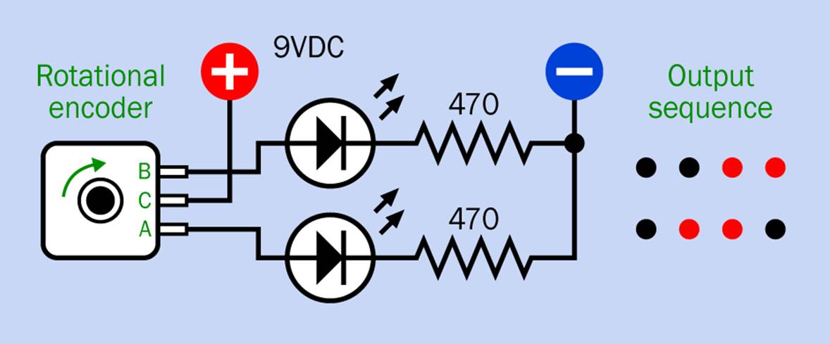
Figure 33-2. When a rotational encoder is wired as shown, its two outer terminals should run through the output sequence shown here.
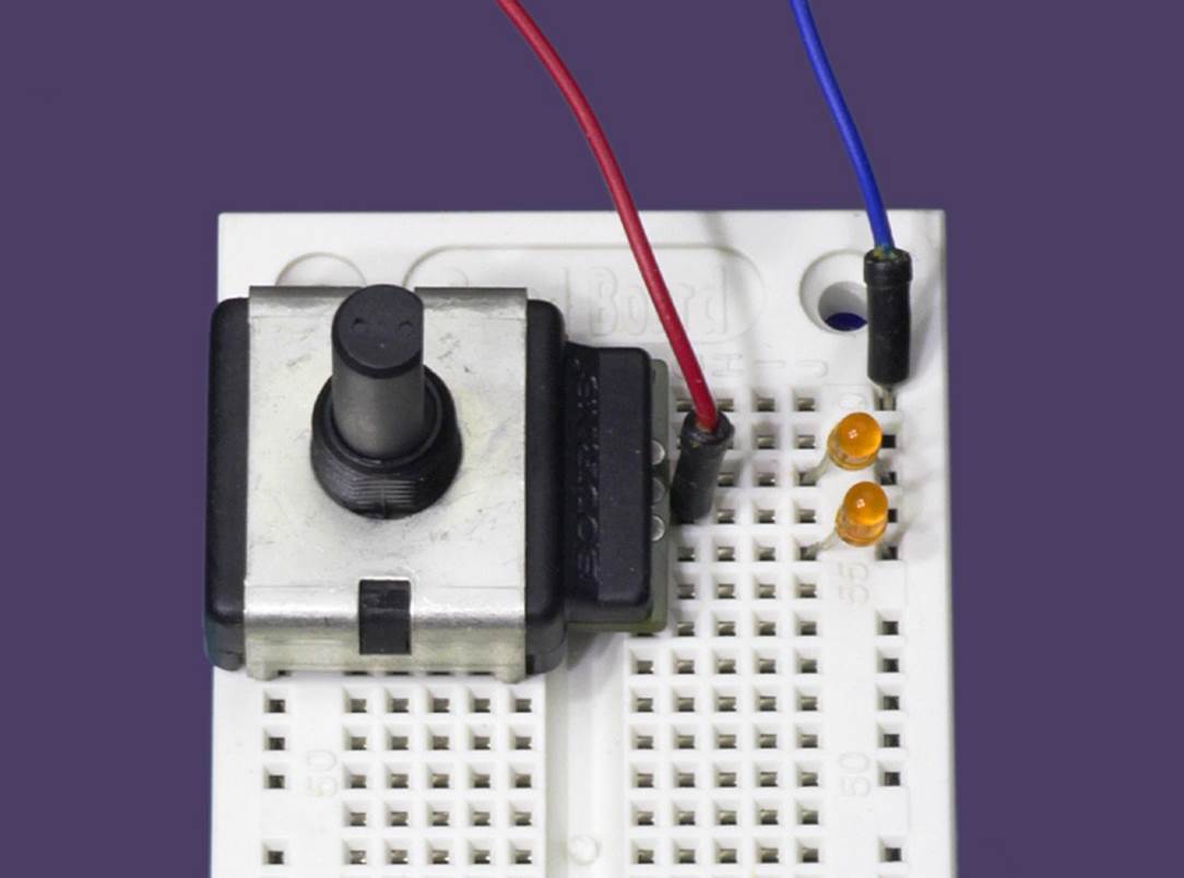
Figure 33-3. Many encoders, such as this one, can be plugged into a breadboard for testing.
Turn the shaft very slowly, and you should see the LEDs lighting up in the output sequence that is shown in Figure 33-2. Now turn the shaft in the opposite direction, and you should see that the pattern reverses itself. This is the pulse train I referred to earlier.
Note that the black dots in the diagram do not represent a logic-low state. An encoder output is either “high” or “off” because it has little switches inside. When they are “off,” they are open circuit and not connected to anything.
An encoder may be wired with negative ground attached to the center terminal, instead of the positive side of the power supply that I have chosen to use. In that case, the output can be thought of as a series of negative and off pulses, instead of positive and off pulses.
Warning: Mediocre Encoders
If the output sequence created by your encoder doesn’t look like the sequence of red and black dots shown in Figure 33-2, or if you see hesitations or flickering, this may be because you are using a cheap encoder. Paying a little more can get you a cleaner, more regular output. This is desirable for the experiment that follows.
Inside the Encoder
The pulses that you have seen are created by two pairs of contacts inside the encoder, mounted slightly out of step with each other (that is, they are out of phase). Figure 33-4 shows this concept.
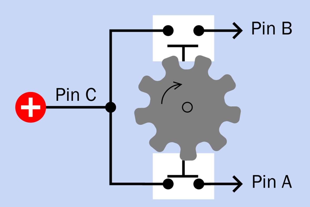
Figure 33-4. In this diagram, the pushbuttons represent pairs of contacts inside a quadrature encoder.
A graphical representation of the output is shown in Figure 33-5. Each of the dashed white lines represents a detent, and the A and B output combination changes from each detent to the next.
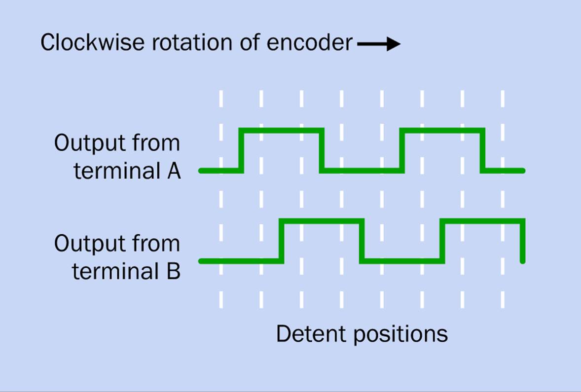
Figure 33-5. Output of an encoder, where the number of detents is the same as the resolution.
The way in which encoders are described can be confusing. Here are the rules:
§ An encoder of the type that I have been describing, with two output terminals that have four possible on-off combinations, is called a quadrature encoder.
§ The resolution is the number of transitions of each terminal, both up and down, multiplied by the number of terminals (two, in the case of a quadrature encoder), within a complete rotation of 360 degrees.
§ Therefore, the resolution is the same as the number of state changes during one revolution.
§ The term “PPR” counts “off” pulses as well as “on” pulses, from both terminals. Therefore PPR means the same thing as resolution.
Encoder Usage
The encoder is a very simple-minded, lazy device. All it does is click its little internal switches, leaving some other component to do the intelligent work of interpreting their sequence.
That other component could be a logic chip—but if you plan to connect a rotational encoder with any type of digital logic, there is a very important point to remember:
§ You must always use pulldown or pullup resistors on encoder outputs so that they have a defined voltage when the switches inside the encoder are open.
This rule also applies when you are using a rotational encoder as an input to a microcontroller, which is its most common application.
Suppose the encoder is functioning as a volume control. When you turn the knob, the microcontroller figures out which way you’re turning it by comparing the pulse trains from the two terminals. For example, if Switch A closes a moment before Switch B, this indicates that the direction of rotation is clockwise. If Switch B closes before Switch A, the direction is counterclockwise.
Having determined that, the microcontroller then counts the number of pulses to find out how much you want to turn the volume up or down.
Programming a microcontroller to respond in this way is more complicated than it seems, because in addition to the other chores, the program should ignore the contact bounce that a rotational encoder creates. Fortunately I don’t have to worry about all this, because I’m not going to be using an encoder with a microcontroller. I have my own peculiar plans for it.
Incidentally, you may be wondering what a rotational encoder is doing in a section of this book devoted to sensors. Surely it’s an input device, not a sensor?
This is true. It is not a sensor. It is an input device—but it’s a useful thing to know about, and I’m going to use it as a sensor.
It Can Be Random
If an encoder is symmetrically designed, and if someone turns the knob to a random position, you will have an equal chance of ending up with outputs A and B both low, or A high and B low, or A low and B high, or A and B both high.
Hmm—those combinations sound like every possible combination of two binary digits—and indeed, they can be used this way.
I explored this idea briefly in a column that I wrote for Make magazine about a “Magic 8 Box” that would function similarly to the old Magic 8 Ball toy. My idea was to attach a lead counterweight to an arm mounted on an encoder shaft, as shown in Figure 33-6.
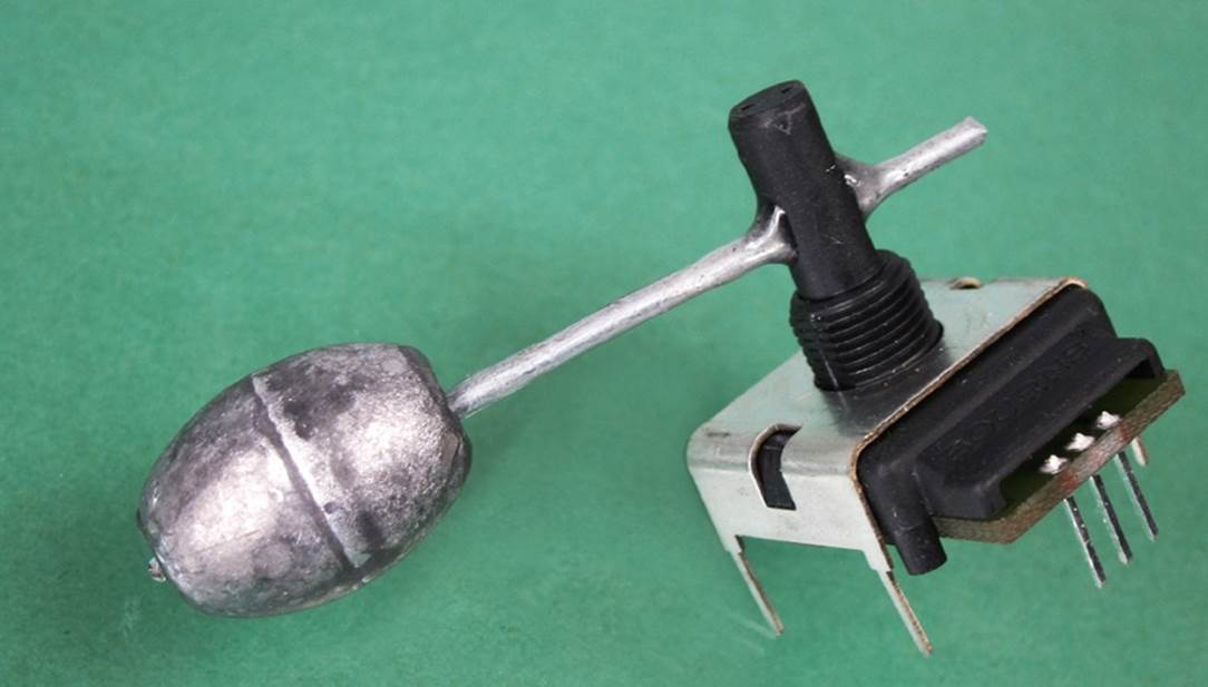
Figure 33-6. A lead sinker weight, normally used by people who go fishing, has been added to this encoder on the end of a stiff piece of galvanized wire.
I drilled a hole through the plastic shaft of an encoder, drilled another hole through the little lead weight, inserted a piece of #14 galvanized wire through both holes, and used epoxy glue to hold it in place.
The wire is a standard item in hardware stores, and I bought a little package of one-ounce lead weights in Walmart. They’re used as “sinkers” by people who catch fish. I don’t go fishing, myself, so I’m a bit sketchy on the exact purpose of sinkers, but you don’t need to know how they are normally used in order to use them for something else. You’ll find them in the fishing section of the sports department.
Now, suppose the rotational encoder is secured firmly to the inside of a box, which also contains a circuit that you have built. Suppose someone turns the box in various random directions. Why would a person do this? Well, maybe you could mount an on-off switch for your circuit on the underside of the box so that the person who wants to use it must turn it over to find the switch. The inertia of the lead weight on the shaft of the encoder will cause the shaft to rotate—and where it stops, nobody knows.
To make things more interesting, suppose we have a second rotational encoder mounted on an inner wall of the box, at 90 degrees to the first. This way, the motion of the box will be sensed along two different axes. Since each encoder delivers a pair of outputs that can be thought of as generating a two-bit binary number in the range 00, 01, 10, and 11, we can combine the outputs from the two encoders to get a four-bit binary number ranging from 0000 to 1111, and it will be totally unpredictable. This can be supplied to the input of a decoder chip or the control pins of a multiplexer, to choose a random number from 0 through 15.
Other ideas are also possible—and indeed, I have one right here.
Rotational Decider
You can reduce the four encoder outputs to a single output that can be either high or low. This could function as a “decision maker” toy, like a very dumbed-down version of the I Ching. Think of a question, pick up the box, shake it, put it down, press a button, and it lights either a “yes” LED or a “no” LED.
Part of the appeal of this toy is that you can feel the encoder detents clicking and the weights shifting when you move the box. It feels as if something really complicated and mysterious is going on in there. (If someone asks you about this, you can tell them that it’s just too complicated and mysterious to explain.)
Perhaps you’re wondering why we need two encoders, each creating four possible states, if all we need is a yes-or-no answer. The reason is that the device should be as unpredictable as possible, and the more inputs you can throw in, the less predictable the final result will be.
But how do you reduce four outputs to one? By XORing them. This is shown in Figure 33-7. Note the four pulldown resistors that insure there is always a defined voltage on the encoder outputs.
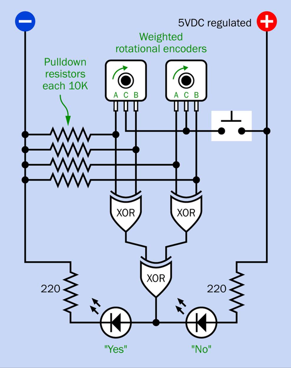
Figure 33-7. This circuit produces a random “yes or no” answer from a couple of weighted rotational encoders.
Trace the logic through this circuit and you’ll find that the output from the XOR gate at the bottom has an equal chance of being high or low—so long as the rotational encoders are behaving in an even-handed fashion.
One nice aspect of this simple circuit is that it needs no on-off switch. The encoders consume no power, so you can shake them into a position and put down the box before you press the button. Depending whether the output of the lowest XOR gate is high or low, the button will power the “Yes” LED or sink current from the “No” LED. Remember, a 74HC00 series logic gate can sink the same amount of current as it will source.
§ You must use an HC series chip in this circuit. It won’t work with older series of chips that have insufficient output power or cannot source as much current as they sink.
A schematic for this circuit is shown in Figure 33-8.
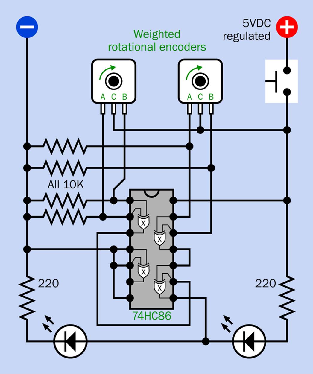
Figure 33-8. Schematic for the encoder-based yes-or-no decider toy.
Rotational Equivocator
Equivocation is what you do when you don’t feel willing to make a decision. Elected legislators do this all the time. For example, if I were a legislator and someone asked me, “Can we adapt the Rotational Decider to become a Rotational Equivocator?” I could say, “Well, there are two sides to this issue; I think something is to be said for both of them, and the topic may need further study.”
Since I’m not a legislator, I won’t say that. I’ll say, “Yes, of course we can build a Rotational Equivocator.”
The logic diagram for it is shown in Figure 33-9. It will light the “Maybe” LED if the left XOR has a high output and the right XOR has a low state. It lights the “Maybe not” if the states are reversed. But what if both XORs have the same output—either both low or both high? In that case, the third XOR has a low output and sinks current through the third LED, which says “I’m not quite sure.”
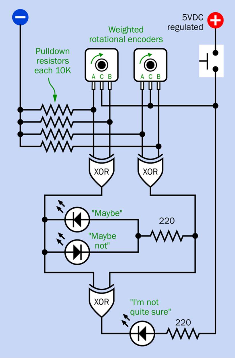
Figure 33-9. The previous yes-no circuit has been modified to give equivocal answers.
The schematic is shown in Figure 33-10, while a photograph of the circuit appears in Figure 33-11. In the photograph, LEDs have been used that contain their own resistors. The rotational encoders have been placed far apart to allow their lead weights to rotate without hitting each other.
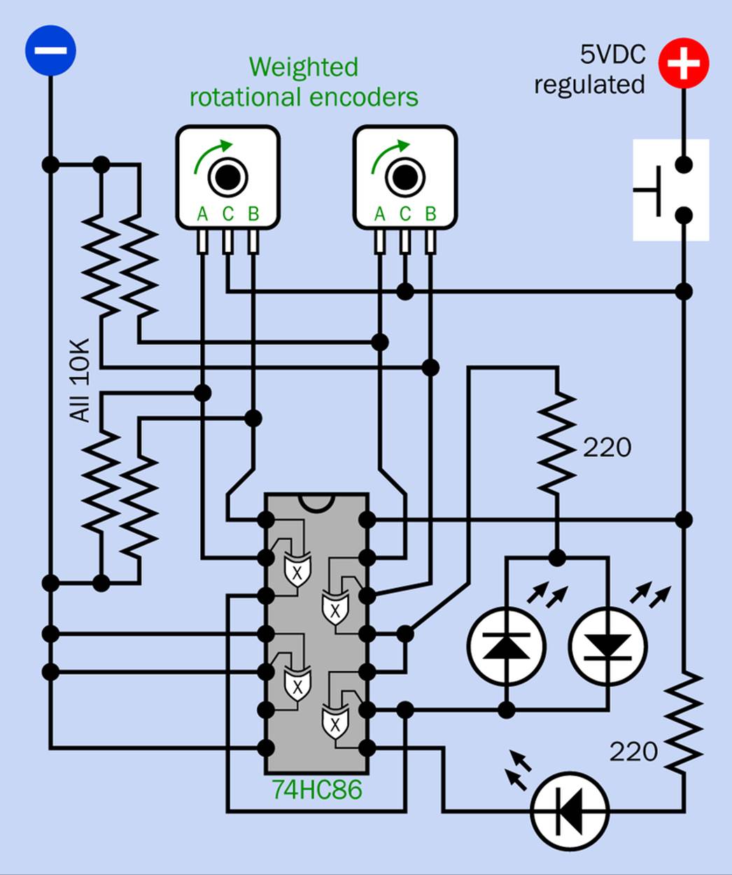
Figure 33-10. The Rotational Equivocator schematic requires only a very small modification of the previous yes-or-no schematic.
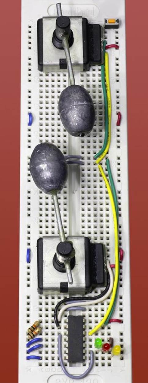
Figure 33-11. Breadboarded version of the Rotational Equivocator. No series resistors are included with the LEDs, as they have their own internal resistors.
If you follow the logic in Figure 33-9, you’ll find that the “Not sure” output is twice as likely as either of the other outputs. This insures that the toy will be as unhelpful as possible.
If you have a friend in politics, maybe you could give this person one of these as a campaign contribution.
Seriously Random
I included this little digression into rotational encoders because I wanted to include an easy project among the more difficult ones, and I enjoy using components for unintended purposes. Also, I like the idea of a toy that requires only one logic chip, a couple of LEDs, and a pushbutton. If you include a 5VDC voltage regulator, you can power it from a 9V battery that should last for several years.
Other types of sensors are really more suitable for creating randomicity. I’m going to suggest several options in the next section, after which I will explain a way to achieve “perfect” randomicity—and I’ll discuss what this really means.
All materials on the site are licensed Creative Commons Attribution-Sharealike 3.0 Unported CC BY-SA 3.0 & GNU Free Documentation License (GFDL)
If you are the copyright holder of any material contained on our site and intend to remove it, please contact our site administrator for approval.
© 2016-2026 All site design rights belong to S.Y.A.