Practical Electronics: Components and Techniques (2015)
Chapter 1. Electrons in Motion
The field of electrical theory and electronics is huge, and it can be somewhat daunting at first. In reality, you don’t need to know all the little theoretical details to get things up and running. But to give your efforts a better chance at success, it is a good idea to understand the basics of what electricity is and how, in general terms, it works. So that’s what we’re going to look at here.
The main intent of this chapter is twofold. First, I want to dispense with the old “water-flowing-in-a-pipe” analogy that has been used in the past to describe the flow of electrons in a conductor; it’s not very accurate and can lead to some erroneous assumptions. There is, I believe, a better way to visualize what is going on, but it does require a basic understanding of what an atom is and how its component parts work to create electric charge and, ultimately, electric current. It might sound rather like something from the realm of physics (and, to be honest, it is, along with chemistry), but once you understand these concepts, things like fluorescent lights, neon signs, lightning, arc welders, plasma cutting torches, heating elements, and the electronic components you might want to use in a project will become easier to understand. The old water-flowing-in-a-pipe model doesn’t really scale very well, nor does it translate easily to anything other than, well, water flowing through a pipe.
Second, I’d like to build on this atom-based model to introduce some basic concepts that will come up later as you work on your own projects. By the end of this chapter, you should have a good idea of what the terms voltage, current, and power mean and how to calculate these values. If you need more details on a lower level, you’ll find them in Appendix A, including overviews of serial and parallel circuits, and basic AC circuit concepts. Of course, numerous excellent texts are readily available on the subject, and I encourage you to seek them out if you would like to dig deeper into the theory of electronics.
If you are already familiar with the basic concepts of electronics, feel free to skip this chapter. Just don’t forget to take advantage of Appendix A and the suggested references in Appendix C if you run into a need for further details somewhere along the line.
Atoms and Electrons
In common everyday usage, the term electricity is used to refer to the stuff that one finds inside a computer, in a wall outlet, in the wires strung between poles beside the street, or at the terminals of a battery. But just what is this stuff, really?
Electricity is the physical manifestation of the movement of electrons, little specks of subatomic matter that carry a negative electrical charge. As we know, all matter is composed of atoms. Each atom has a nucleus at its core with a net positive charge. Each atom also has one or more negative electrons bound to it, each one whipping around the positively charged nucleus in a quantum frenzy.
It is not uncommon to hear of the “orbit” of an electron about the nucleus, but this isn’t entirely accurate, at least not in the classical sense of the term orbit. An electron doesn’t orbit the nucleus of an atom in the way a planet orbits a star or a satellite orbits the earth, but it’s a close enough approximation for our purposes.
In reality, it’s more like layers of clouds wrapped around the nucleus, with the electrons being somewhere in the layers of the cloud. One way to think of it is as a probability cloud, with a high probability that the electron is somewhere in a particular layer. Due to the quirks of quantum physics, we can’t directly determine where an electron is located in space at any given time without breaking things, but we can infer where it is by indirect measurements. Yes, it’s a bit mind-numbing, so we won’t delve any deeper into it here. If you want to know more of the details, I would suggest a good modern chemistry or physics textbook, or for a more lightweight introduction, you might want to check out the “Mr. Tompkins” series of books by the late theoretical physicist George Gamow.
The nucleus of most atoms is made up of two basic particles: protons and neutrons, with the exception of the hydrogen atom, which has only a single positive proton as its nucleus. A nucleus may have many protons, depending on what type of atom it happens to be (iron, silicon, oxygen, etc.). Each proton has a positive charge (called a unit charge). Most atoms also have a collection of neutrons, which have about the same mass as a proton but no charge (you might think of them as ballast for the atom’s nucleus). Figure 1-1 shows schematic representations of a hydrogen atom and a copper atom.
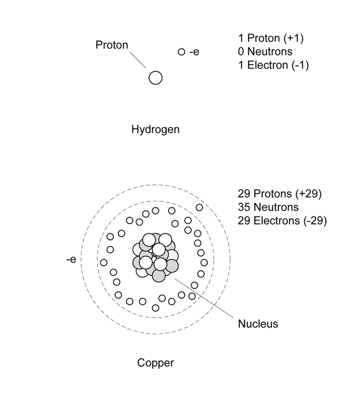
Figure 1-1. Hydrogen and copper atoms
The +1 unit charges of the protons in the nucleus will cancel out the –1 unit charges of the electrons, and the atom will be electrically neutral, which is the state that atoms want to be in. If an atom is missing an electron, it will have a net positive charge, and an extra electron will give it a net negative charge.
The electrons of an atom are arranged into what are called orbital shells (the clouds mentioned earlier), with an outermost shell called the valence shell. Conventional theory states that each shell has a unique energy level and each can hold a specific number of electrons. The outermost shell typically determines the chemical and conductive properties of an atom, in terms of how easily it can release or receive an electron. Some elements, such as metals, have what is considered to be an “incomplete” valence shell. Incomplete, in this sense, means that the shell contains fewer than the maximum possible number of electrons, and the element is chemically reactive and able to exchange electrons with other atoms. It is, of course, more complex than that, but a better definition is way beyond the scope of this book.
For example, notice that the copper atom in Figure 1-1 has 29 electrons and one is shown outside of the main group of 28 (which would be arranged in a set of shells around the nucleus, not shown here for clarity). The lone outermost electron is copper’s valence electron. Because the valence shell of copper is incomplete, this electron isn’t very tightly bound, so copper doesn’t put up too much of a fuss about passing it around. In other words, copper is a relatively good conductor.
An element such as sulfur, on the other hand, has a complete outer shell and does not willingly give up any electrons. Sulfur is rated as one of the least conductive elements, so it’s a good insulator. Silver tops the list as the most conductive element, which explains why it’s considered useful in electronics. Copper is next, followed by gold. Still, other elements are somewhat ambivalent about conducting electrons, but will do so under certain conditions. These are called semiconductors, and they are the key to modern electronics.
This should be a sufficient model for our purposes, so we won’t pry any further into the inner secrets of atomic structure. What we’re really interested in here is what happens when atoms do pass electrons around, and why they would do that to begin with.
Electric Charge and Current
Electricity involves two fundamental phenomena: electric charge and electric current. Electric charge is a basic characteristic of matter and is the result of something having too many electrons (negative charge), or too few electrons (positive charge) with regard to what it would otherwise need to be electrically neutral. An atom with a negative or positive charge is sometimes called an ion.
A basic characteristic of electric charges is that charges of the same kind repel one another, and opposite charges attract. This is why electrons and protons are bound together in an atom, although under most conditions they can’t directly combine with each other because of some other fundamental characteristics of atomic particles (the exceptional cases are a certain type of radioactive decay and inside a stellar supernova). The important thing to remember is that a negative charge will repel electrons, and a positive charge will attract them.
Electric charge, in and of itself, is interesting but not particularly useful from an electronics perspective. For our purposes, really interesting things begin to happen only when charges are moving. The movement of electrons through a circuit of some kind is called electric current, or current flow, and it is also what happens when the static charge you build up walking across a carpet on a cold, dry day is transferred to a doorknob. This is, in effect, the current (flow) moving between a high potential (you) to a lower potential (the doorknob), much like water flows down a waterfall or a rock falls down the side of a hill. The otherwise uninteresting static charge suddenly becomes very interesting (or at least it should get your attention). When a charge is not in motion, it is called the potential, and yes, we can make an analogy between electrical potential and mechanical potential energy, as you’ll see shortly.
Current flow arises when the atoms that make up the conductors and components of electrical circuits transfer electrons from one to another. Electrons move toward things that are positive, so if you have a small light bulb attached to a battery with some wires (sometimes also known as aflashlight), the electrons move out of the negative terminal of the battery, through the light bulb, and return back into the positive terminal. Along the way, they cause the filament in the lamp to get white-hot and glow.
Figure 1-2, a simplified diagram of some copper atoms in a wire, shows one way to visualize the current flow. When an electron is introduced into one end of the wire, it causes the first atom to become negatively charged. It now has too many electrons. Assuming a continuous source of electrons, the new electron cannot exit the way it came in, so it moves to the next available neutral atom. This atom is now negative and has a surplus electron. In order to become neutral again (the preferred state of an atom), it then passes an extra electron to the next (neutral) atom, and so on, until an electron appears at the other end of the wire. So long as there is a source of electrons under pressure connected to the wire and a return path for the electrons back to the source, current will flow. The pressure is called voltage, which “Current Flow in a Basic Circuit” will discuss in more detail.
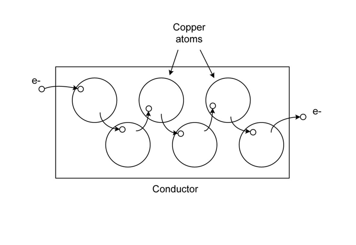
Figure 1-2. Electrons moving in a wire
Figure 1-3 shows another way to think about current. In this case, we have a tube (a conductor) filled end to end with marbles (electrons).
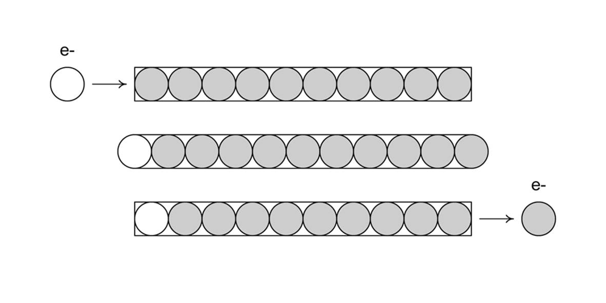
Figure 1-3. Modeling electrons with marbles in a tube
When we push a marble into one end of the tube in Figure 1-3, a marble falls out the opposite end. The net number of marbles in the tube remains the same. Note that the electrons put into one end of a conductor are not necessarily the ones that come out the other end, as you can see from Figures 1-2 and 1-3. In fact, if the conductor is long enough, the electrons introduced at one end might not be the ones that appear at the other end, but electrons would appear, and you would still be able to measure electron movement in the conductor.
Current Flow in a Basic Circuit
Electricity flows when a closed circuit allows for the electrons to move from a high potential to a lower potential in a closed loop. Stated another way, current flow requires a source of electrons with a force to move them, as well as a return point for the electrons.
Electric current flow (a physical phenomenon) is characterized by four fundamental quantities: voltage, current, resistance, and power. We’ll use the simple circuit shown in Figure 1-4 as our baseline for the following discussion. Notice that the circuit is shown both in picture and schematic form. For more about schematic symbols, refer to Appendix B.
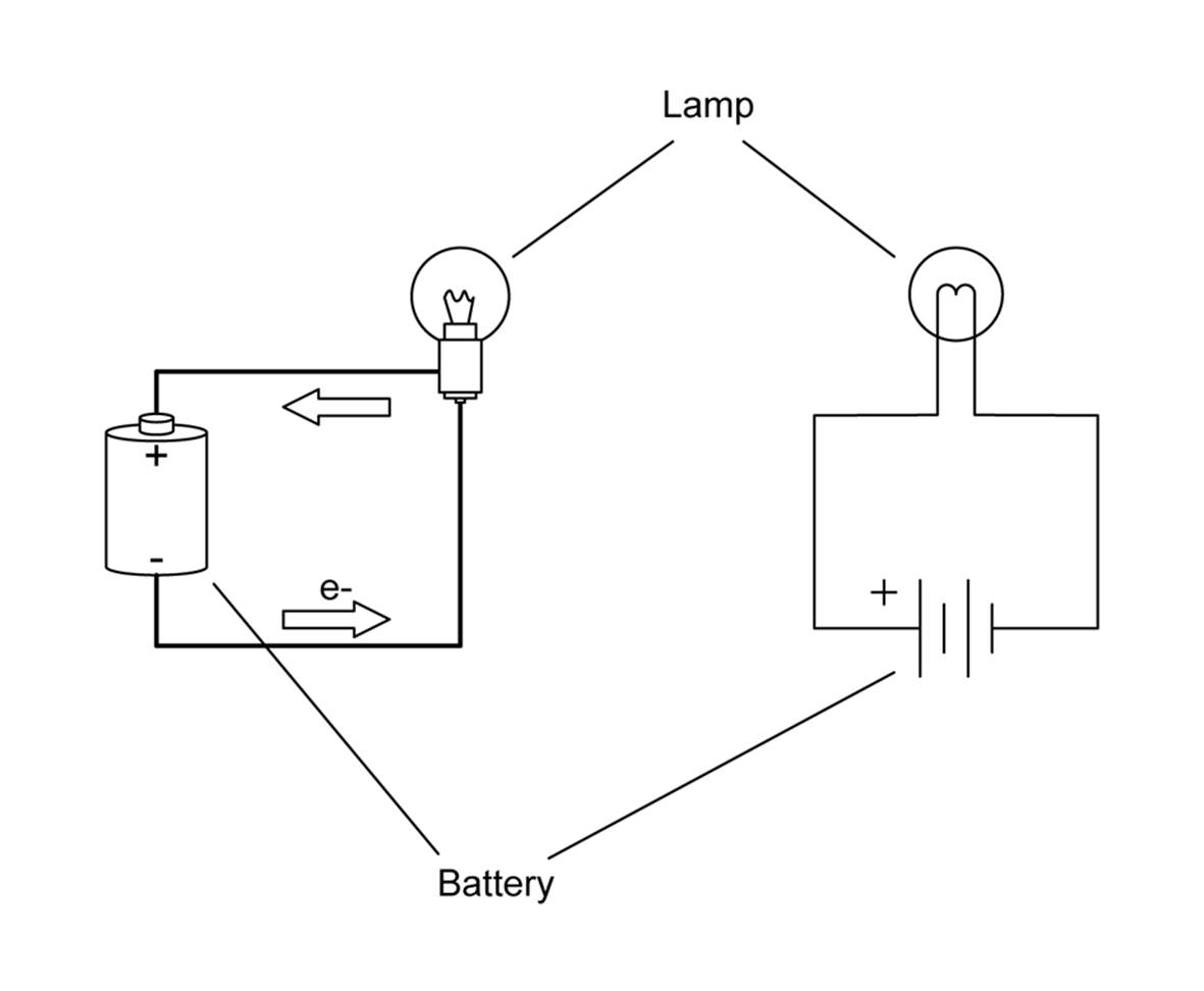
Figure 1-4. A simple DC circuit
A few words about the term current are in order here. The word has more than one meaning in electronics, which can be confusing at first. In one sense, current refers to the flow of electrons through a conductor of some kind. It is a reference to the movement of charge carried by the electrons. In the other sense, current refers to the number of electrons moving through the conductor. In this sense, it specifies the volume of electrons moving past some point in the circuit at some point in time. In other words, the measurement of current is the determination of the quantity of electrons in motion.
One way to think about current is to remember that it cannot be measured without movement, so when you see or hear the word current, it is usually referring to movement. To make the distinction clear, the term current flow is often used to mean movement of electrical charges. Static charges, even if just at the terminals of a common battery, have no current flow and hence no measurable current.
Current that flows in only one direction, as in Figure 1-4, is called direct current (DC). A common battery produces DC, as does the DC power supply in a typical computer system. Current that changes direction repeatedly is called alternating current (AC). AC is what comes out of a household wall socket (in the US, for example). It is also the type of current that drives the loudspeakers in a stereo system. The rate at which the current changes direction is called the frequency and is measured in cycles per second in units of Hertz (abbreviated Hz). So, a 60 Hz signal is made up of a current flow changing direction 60 times per second. When AC is used to drive a loudspeaker, a signal with a frequency of 440 Hz will be A above middle C to our ears.
By convention, DC is described as flowing from positive to ground (negative), whereas in reality, electrons flow from the negative terminal to the positive terminal of the power source. In Figure 1-4, the arrows show the electron flow. Basically, the discrepancy stems from an erroneous assumption made by Benjamin Franklin, who thought that electrons had a positive charge and flowed from positive to negative terminals. He guessed wrong, but we ended up with a convention that was already well ingrained by the time physicists figured out what was really going on. Hence we have conventional current flow and electron current flow. Although you should be aware of this discrepancy, from this point onward, we’ll use conventional current flow, since that is what most of the electronics industry uses.
A volt (V) is the unit of measurement used for electric potential difference, electric potential, and electromotive force. When the term voltage is used, it usually refers to the electric potential difference between two points. In other words, we say that a static charge has a value of some number of volts (potential), but there is a certain amount of voltage between two points in a circuit (potential difference).
Voltage can be visualized as a type of pressure, or driving force (although it is not actually a force in a mechanical sense). This is the electromotive force (emf) produced by a battery or a generator of some type, and the emf can drive a current through a circuit. And even though it may not look like a generator, a power supply (like the one that plugs into the wall socket to charge a cell phone) is really nothing more than a converter for the output of a generator at a power plant somewhere.
Another way to think of voltage is as the electric potential difference between two points in an electric field. It is similar to the difference in the potential energy of a cannonball at the top of a ladder as opposed to one at the top of a tall tower. Both cannonballs exist in the earth’s gravitational field, they both have potential energy, and it took some work to get them both into position. When they are released, the cannonball on the top of the tower will have more energy when it hits the ground than the cannonball dropped from the top of the ladder, because it had a larger potential energy due to its position.
These two descriptions of voltage are really just opposite sides of the same coin. In order to create a potential difference between two points, work must be done. When that energy is lost or used, there is a potential drop. When the cannonball hits the ground, all of the energy put into getting it into position against the pull of gravity is used to make a nice dent in the ground.
The main point here to remember is that a high voltage has more available electrical energy (pressure) than a low voltage. This is why you don’t get much more than a barely visible spark when you short out a common 9-volt battery with a piece of wire, but lightning, at around 10,000,000 volts (or more!), is able to arc all the way between a cloud and the ground in a brilliant flash. The lightning has more voltage and hence a larger potential difference, so it is able to overcome the insulating effects of the intervening air.
Whereas voltage can be viewed as electrical pressure, current is the measure of the quantity, or volume, of electrons moving through a circuit at some given point. Remember that the term current can have two different meanings: electron movement (flow) and the volume of the electron flow. In electronics, the word current usually means the quantity of electrons flowing through a conductor at a specific point at a single instant in time. In this case, it refers to a physical quantity and is measured in units of amperes (abbreviated as A).
Now that we’ve looked at voltage and current, we can examine some of the things that happen while charge is in motion (current flow) at some particular voltage. No matter how good a conventional conductor happens to be, it will never pass electrons without some resistance to the current flow (superconductors get around this, but we’re not going to deal with that topic here). Resistance is the measure of how much the current flow is impeded in a circuit, and it is measured in units of ohms, named after German physicist Georg Simon Ohm. “Resistance” has more details about the physical properties of resistance, but for now, let’s consider how resistance interacts with current flow.
You might think of resistance as an analog of mechanical friction (but the analogy isn’t perfect). When current flows through a resistance, some of the voltage potential difference is converted to heat, and there will be a voltage drop across the resistor. How much heat is generated is a function of how much current is flowing through the resistance and the amount of the voltage drop. We’ll look at this more closely in “Power”.
You can also think of resistance as the degree of “stickiness” that an atom’s valence shell electrons will exhibit. Atoms that can give up or accept electrons easily will have low resistance, whereas those that want to hold onto their electrons will exhibit higher resistance (and, of course, those that don’t readily give up electrons under normal conditions are good insulators).
Carbon, for example, will conduct electricity, but not as easily as copper. Carbon is a popular material for fabricating the components called resistors used in electronic circuits. Chapter 8 covers passive components, such as resistors.
Ohm’s Law
As you may have already surmised, there is a fundamental relationship between voltage, current, and resistance. This is the famous equation called Ohm’s law. It looks like this:
E = IR
where E is voltage (in volts), I is current (in amperes), and R is resistance (in ohms).
This simple equation is fundamental to electronics, and indeed it is often the only equation that you really need to get things going. In Figure 1-4, the circuit has only two components: a battery and a lamp. The lamp comprises what is called the load in the circuit, and it exhibits a resistance to current flow. Incandescent lamps have a resistance that varies according to temperature, but for our purposes, we’ll assume that the lamp has a resistance of 2 ohms when it is glowing brightly.
The battery is 1.5 volts, and for the purposes of this example, we’ll assume that it is capable of delivering a maximum current of 2,000 milliamps (or mA) for one hour at its rated output voltage. This is the battery’s total rated capacity, which is usually around 2,000 mAh (milliamp-hour) fora typical alkaline AA type battery. A milli is one-thousandth of something, so 2,000 mA is the same as 2 amps of current.
Applying Ohm’s law, we can find the amount of current the lamp will draw from the battery by solving for I:
I = E/R
or:
I = 1.5/2
I = 0.75 A
Here, the value for I can also be written as 750 mA (milliamperes). If you want to know how long the battery will last, you can divide its capacity by the current in the circuit:
2/0.75 = 2.67 hours (approximately)
Power
In the simple circuit shown in Figure 1-4, the flow of electrons through the filament in the lamp causes it to heat up to the point where it glows brightly (between 1,600 to 2,800 degrees C or so). The filament in the lamp gets hot because it has resistance, so current flows less easily through the filament than it does through the wires in the circuit.
Power is the rate of doing work per unit of time, and is measured in watts. One watt is defined as the use or generation of 1 joule of energy per second. In an electrical circuit, a watt can also be defined as 1 ampere of current moving through a resistance at 1 volt of potential, and when charges move from a high voltage to a low voltage (a potential difference) across a resistive device, the energy in the potential is converted to some other form, such as heat or mechanical energy.
We can calculate power (P) in a DC circuit by multiplying the voltage by the current:
P = EI
In the case of the simple flashlight circuit, the power expended to force the current through the filament is expressed as heat, and subsequently as light when the filament gets hot enough to glow. If you want to know how much power the light bulb in our circuit is consuming, simply multiply the voltage across the bulb by the current:
P = 1.5 × 0.75
P = 1.125 watts, or 1.125W
Let’s compare this power value with the rating for a common incandescent light bulb with a 100W rating. An old-style 100W light bulb operating at 110 VAC (volts AC, typical household voltage in the US) will use:
I = PE
I = 100/110
I = 0.9A
Amazing! The large light bulb consumes only a bit more current than the tiny light bulb connected to a battery! How can this be?
The difference lies in the voltage supplied to the light bulbs and their internal resistance. Now that you have an estimate of the amount of current flowing through a 100W bulb, you could easily work out what its internal resistance might be. You should also be able to see why leaving lights on (or using old-style light bulbs at all) is wasteful. The current adds up, and each watt of power costs money.
Resistance
Now let’s look at the phenomenon of resistance more closely, since it is such a fundamental aspect of electronics. Formally stated, 1 ohm is equal to the resistance between two points of a conductor when a potential of 1 volt produces a current of 1 ampere. This is, of course, the relationship defined by Ohm’s law, discussed in “Ohm’s Law”.
Resistance is a key factor in electric circuits, which is why it is one of the three variables in the Ohm’s law equation. As stated earlier, every circuit has some amount of resistance, except for things like exotic superconductors. Even the wires connecting a battery to a device have some intrinsic resistance.
Switches have internal resistance, as do connectors and even the copper traces on a printed circuit board (PCB). Figure 1-5 illustrates this by showing a simple DC circuit and its resistance equivalent.
You might notice in Figure 1-5 that even the battery has some internal resistance. Appendix A discusses series and parallel resistances, and how to calculate their values, but the point here is to show how nothing is free in the world of circuits. Resistance is everywhere, as far as electrons are concerned.
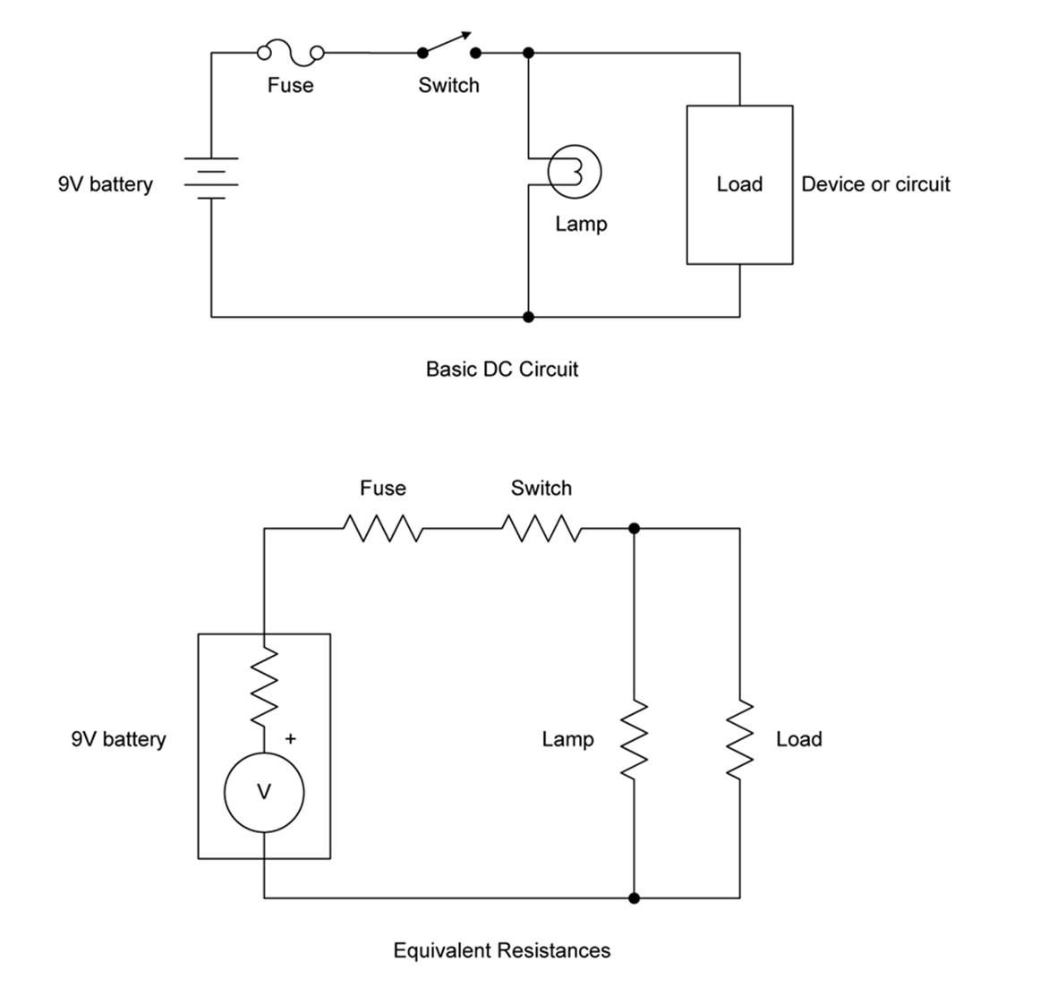
Figure 1-5. Circuit resistance example
Normally, this intrinsic resistance is ignored, as it tends to be small and doesn’t really impact the overall operation of a device. However, if the device is a low-current one intended to run for a long time without the battery being changed, then it starts to become something to consider. Resistance to current flow means that energy is being expended pushing electrons through the resistive element, and that energy is dissipated as heat. Unless you are intentionally using a resistance as a heater (which is what electrical heating elements do), it is being wasted.
In electronics, the passive components called resistors are probably the most commonly used parts. Resistors come in a range of values and power ratings, from ultra-tiny little flecks for surface-mount use to huge devices used in diesel-electric locomotives to dissipate excess energy created during dynamic braking. Figure 1-6 shows a typical 1/4-watt carbon composition resistor. See Chapter 8 for more information about resistors and other passive components.
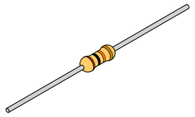
Figure 1-6. A typical resistor
Resistors can be used to limit current, reduce voltages, and supply a specific voltage at a particular location in a circuit. Resistance plays a big role in analytical applications such as network analysis (electrical networks, not data networks), equivalent circuits theory, and power distribution modeling.
Example: Building a Voltage Divider
You can do a lot with just a power supply of some sort, a couple of resistors, and Ohm’s law. For example, let’s say that you wanted to supply a circuit with 5V DC from a 9V battery. Provided that the circuit doesn’t draw very much current (perhaps a few milliamps or so), and you are not too concerned about how stable the 5V supply will be, a simple thing called a voltage divider (shown in Figure 1-7) will do the job.
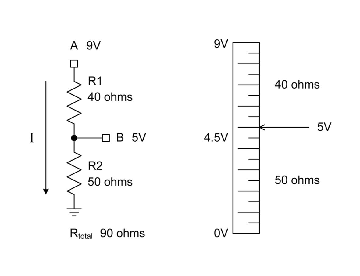
Figure 1-7. A simple voltage divider
We want the voltage at point B to be 5V when we apply 9V to point A. I’ve selected resistor values that will result in 100 mA of current flowing through both of the resistors. I’ve not taken into account the current consumed by the circuit connected to point B, but since the assumption here is that it will draw very little current, it won’t have that big of an effect on the voltage level at point B.
Notice that the two resistors in the voltage divider of Figure 1-7 aren’t the same values. One is 40 ohms; the other is 50 ohms. If both R1 and R2 were the same value, the voltage at point B would be 4.5V, not the 5V we want.
So how did I get those values? First, we determine the total resistance of the divider circuit. Since we already know the input voltage and the amount of current we want to pass through the resistors, the solution looks like this:
R = E/I
R = 9/0.1
R = 90
And, since there are two resistors in the divider, the sum of their values must be equal to the total resistance:
R1 + R2 = 90
If we use the current and the target output voltage of the divider (point B), we get the value of the second resistor, R2:
R2 = 5/0.1
R2 = 50
R1 is just whatever is left over:
R1 = 90 - R2
R = 40
The ratio between R1 and R2 and the resulting voltage at point B is illustrated graphically in Figure 1-7 by the vertical scale on the right side of the figure.
Another way to do this doesn’t require any knowledge of the current through the divider, but instead uses the ratio of the two resistors:
Vout = Vin × (R2/(R1 + R2))
Now, how long will the 9V battery last? A typical garden-variety 9V alkaline battery has a capacity rating of about 550 mAh. We can apply the same math used with the simple lamp circuit earlier. If we divide the battery’s capacity rating by the current consumption of the voltage divider, we get this:
550/100 = 5.5
So, with this circuit, the battery will last for about 5.5 hours in continuous use.
As an exercise, calculate how much power this simple circuit will dissipate. Since resistors are rated in terms of both resistance and power dissipation, it should be quickly obvious that the two components will need to be rated for around 1 watt each. This circuit would overwhelm a small 1/8 watt component.
Also, I mentioned earlier that I was assuming that whatever was connected to the divider at point B wouldn’t be drawing very much current. You could probably increase the values of the resistors by an order of magnitude (× 10), thereby reducing the total current to 10 mA, and still have enough margin to provide a very small current at around 5V. This would increase the battery life to 55 hours or so and significantly reduce the power rating requirement for the resistors. When you are using a voltage divider to produce a reference voltage for an active component in a circuit, the current draw is often very small (perhaps in the microamps range), since it’s the voltage that matters. In cases like this, the values of R1 and R2 can be very large to further reduce the amount of current consumed by the divider.
This little exercise should make a few things readily apparent. First, you really don’t want to use a voltage divider to try to create the equivalent of a power supply. Active regulators do a much better job and don’t waste lots of energy as heat without doing any meaningful work. We will take a look at power supplies in Chapter 5 and active components like voltage regulators in Chapter 9.
Second, with multiple variables to work with, there is a lot of room to seek out solutions, some better than others. Don’t settle on the first solution that pops up, because there might be a better way. Lastly, batteries are great for portability, but they really don’t last long in continuous use when significant current is involved.
Summary
In this chapter, we’ve looked at the basics of atomic structure and how that contributes to how electrons move. We’ve also looked at the basic concepts of voltage, current, power, and resistance. In the process, we discovered that something rated for 100 watts of power at 110 volts uses only slightly more current than something at 1.25 watts at 1.5 volts, with the voltage being a major factor in the power difference.
With what you’ve seen so far, you should be able to determine how much power an electronic device is dissipating and determine how long a battery will last in a given situation, so long as you know the amount of current the battery is called upon to supply.
That should be enough basic theory to get things moving along, and later chapters will introduce additional concepts as necessary. If you really want to dig into the theoretical end of things to gain a deeper understanding, I would suggest one of the excellent reference works listed inAppendix C. Also note that Appendix B contains a listing of various schematic symbols commonly encountered in electronics work, as well as a write-up on using a schematic capture tool to create neat and tidy drawings of your circuits.
All materials on the site are licensed Creative Commons Attribution-Sharealike 3.0 Unported CC BY-SA 3.0 & GNU Free Documentation License (GFDL)
If you are the copyright holder of any material contained on our site and intend to remove it, please contact our site administrator for approval.
© 2016-2026 All site design rights belong to S.Y.A.