Raspberry Pi Hacks (2014)
Chapter 3. Raspberry Pi Around the House
Your Raspberry Pi has one handy feature when it comes to household projects: its size. You can easily hide it in a wall or behind a piece of furniture or put it inside larger build projects like robots and costumes.
This chapter will give you ideas for using your Raspberry Pi for assorted projects around the house, from the practical (like [Hack #31], printing from all your computers to one printer) to the simply fun (like [Hack #35], using your Pi in your next Halloween costume).
Hack 30. Share Files with Samba
We accept that there’s a possibility not all of the computers in your house run Linux. Some might even use Windows (like that one used for PlayOn in [Hack #54]). In that case, this hack should help your systems communicate.
Samba is an open source suite of tools for SMB/CIFS clients. In plainspeak, it lets a Linux computer (like your Raspberry Pi) talk to a Windows machine as if it were a Windows file or print server.
SMB (Server Message Block) is a protocol for sharing files, printers, and assorted communications. CIFS (Common Internet File System) is the modern form of SMB. SMB was designed to run on the NetBIOS API and runs by default on versions of Windows since Windows 2000. Samba started as a project to reverse engineer SMB to allow users on Microsoft systems to access files on Sun systems.
Samba works by creating a network share for directories and subdirectories you choose on your Raspberry Pi. From your Windows machine, you can mount the share with smbmount, and they will look like networked Windows folders. There is also an smbclientutility that will feel like using an FTP program, if you’re more comfortable with that method.
Samba requires two daemons, smbd for the sharing services and nmbd for the NetBIOS name requests, which are controlled by the smb service. (You can use a third daemon, winbindd, to help the Linux machine understand the Windows user and group information on Windows NT 2000 and Windows Server 2003 systems.)
LET’S SAMBA!
Samba is also a Brazilian dance style popularized by Carmen Miranda, or as you may know her, “the person who inspired the Bugs Bunny cartoons in which he wears a hat made of fruit.” Despite thorough experimentation on the authors’ part, there is no evidence that dancing the samba with your Raspberry Pi will do anything but make you look silly.
The name was borrowed for the software we’re discussing here by grepping a UNIX system’s dictionary for words that had the letters S, M, and B. You can try this yourself by running grep -i ^s.*m.*b /usr/share/dict/words, although as of a 1998 message about the history of Samba, creator Andrew Trigdell notes, “Strangely enough, when I repeat that now I notice that Samba isn’t in /usr/dict/words on my system anymore!” We’re just glad he didn’t go with “Sulphmethemoglobin.”
We’ll assume you’re using a USB external hard drive with your Raspberry Pi for this project (and it’s likely you’ll want to if you’re bothering with Samba). If you’re starting from scratch, consider formatting it as either FAT32 or NTFS (if you’re borrowing it from a Windows machine, it probably already is). It’s not really necessary, but it will be handy later if you decide to no longer use it with the Raspberry Pi and want to use that drive with the Windows machine.
Locate said drive (or USB flash drive or just the SD card—whatever you’re intending to share):
$ fdisk -l
The output will look something like this:
Disk /dev/mmcblk0: 7822 MB, 7822376960 bytes
4 heads, 16 sectors/track, 238720 cylinders, total 15278080 sectors
Units = sectors of 1 * 512 = 512 bytes
Sector size (logical/physical): 512 bytes / 512 bytes
I/O size (minimum/optimal): 512 bytes / 512 bytes
Disk identifier: 0x000d4f0f
Device Boot Start End Blocks Id System
/dev/mmcblk0p1 4096 147455 71680 c W95 FAT32 (LBA)
/dev/mmcblk0p2 151552 15278079 7563264 83 Linux
Disk /dev/sda: 1037 MB, 1037041664 bytes
2 heads, 63 sectors/track, 16075 cylinders, total 2025472 sectors
Units = sectors of 1 * 512 = 512 bytes
Sector size (logical/physical): 512 bytes / 512 bytes
I/O size (minimum/optimal): 512 bytes / 512 bytes
Disk identifier: 0x0101bc87
Device Boot Start End Blocks Id System
/dev/sda1 * 32 2025471 1012720 6 FAT16
The first disk, /dev/mmcblk0, is the SD card in the Raspberry Pi. The second, /dev/sda/, is a USB flash drive we put in one of the Pi’s USB connections to use as the example shared storage. Create a mount directory for the drive:
$ mkdir /mnt/PiShare
To see whether you were successful, run ls /mnt, and you should see PiSamba listed.
Open /etc/fstab in your favorite text editor, so you can tell it to connect to PiSamba at boot:
$ sudo vi /etc/fstab
The contents of the file will look something like this:
#
# /etc/fstab
# Created by anaconda
#
# Accessible filesystems, by reference, are maintained under '/dev/disk'
# See man pages fstab(5), findfs(8), mount(8) and/or blkid(8) for more info
#
LABEL="rootfs" / ext4 defaults,noatime 1 1
LABEL="boot" /boot vfat noauto,comment=systemd.automount 1 2
/swap0 swap swap
Add the following line at the bottom:
/dev/sda1 /mnt/PiShare vfat defaults 0 0
For the first part, use the device name you saw listed when you ran fdisk (in this example, /dev/sda/). Be sure to change PiSamba if you used a different name for your mount, and make ntfs-3g whatever type of hard drive format you used. Save the file, exit, and mount the share:
$ mount -a
If you run ls /mnt/, you should see your files. If you don’t, check your disk type in the line you added in /etc/fstab.
Samba is included with many Linux distributions and is set to start automatically. It is not, however, necessarily included with your Raspberry Pi Linux distribution. But that’s easy to fix.
To install Samba on Pidora, run the following command:
$ sudo yum install samba
For Raspbian, run this one:
$ sudo apt-get install samba samba-common-bin
Once it’s installed, the service will start automatically. The Samba configuration file lives in /etc/samba/smb.conf. Open it in your editor to get it set up for your particular needs.
If you’re nervous about editing config files, create a backup first by running cp /etc/samba/smb.conf /etc/samba/smb.conf.backup.
It’s also a well-commented file, so feel free to read it all to get a better feel for what you’re doing:
$ sudo vi /etc/samba/smb.conf
At the bottom of the first large chunk of comments, you’ll see this:
[global]
workgroup = WORKGROUP
#usershare allow guests = yes
#security=share
security=user
follow symlinks = yes
wide links = no
unix extensions = no
lock directory = /var/cache/samba
[pi]
browsable = yes
read only = no
#guest ok = yes
valid users = pi
path = /home/pi
#force user = pi (no longer needed)
[devices]
browsable = yes
read only = no
#guest ok = yes
valid users = pi
path = /media
force user = root
Add this to the bottom of the file:
[PiShare]
browsable = yes
read only = no
path = /mnt/PiShare
create mask = 0660
directory mask = 0771
Save the file, exit, and restart Samba. On Pidora, reboot the Samba service with:
$ su -c '/sbin/service smb restart'
On Raspbian, use:
$ su -c '/etc/init.d/samba restart'
CONFIGURE SAMBA WITHOUT THE COMMAND LINE
If you’re using Pidora, a package available for the GUI Samba Server Configuration Tool can modify the /etc/samba/ files for you. To install this tool, run:
$ su -c 'yum install system-config-samba'
You can start it from the command line by typing system-config-samba.
Now connect to your share from another machine. From Fedora, for example, use the Connect to Server dialog (similar dialogs exist in any Linux distribution or on OS X or Windows). The share address is smb:// followed by the IP address, a slash, and the name of your share, as shown in Figure 3-1.
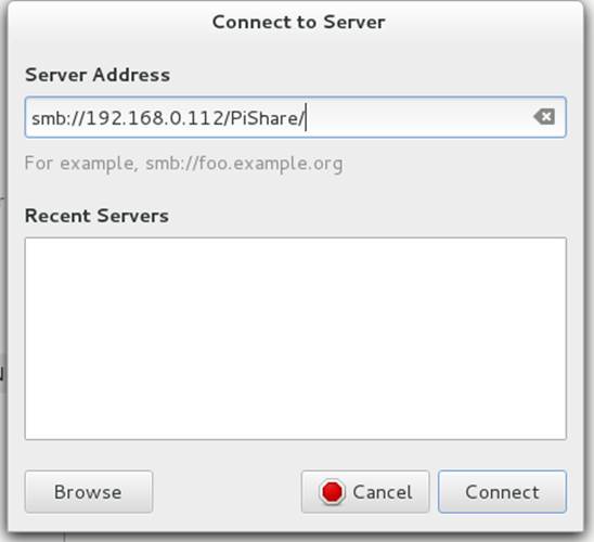
Figure 3-1. Fedora Connect to Server dialog
Finally, you’ll be asked to log in. Use the information you set in /etc/samba/smb.conf, as shown in Figure 3-2.
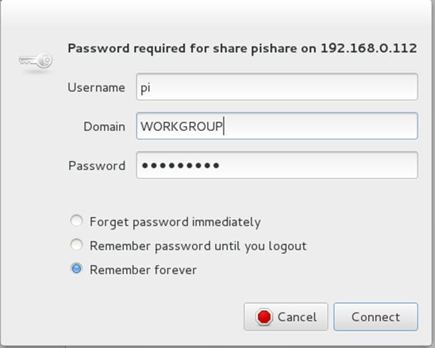
Figure 3-2. Log into shared drive
Your drive is now shared and accessible from beyond your Pi.
Hack 31. Use Your Raspberry Pi as a Remote Print Server
You’re never on the computer with the bulky, unsightly printer when you want to print something. The Raspberry Pi is small enough that you can hide your printer just about anywhere and let the Pi do the work of being a print server.
You might think it would be nice to hide the bulky printer out of sight, but you’ll need to connect to it to actually print something. If you connect the printer to a discreet Pi running as a print server, you can connect to it from your primary computer remotely. You might even be able to find ways to mount the Pi on the back of the printer, or just tuck it away nearby. Either way, physically connect the printer cable to your Raspberry Pi, and let’s get started!
The easiest and most logical way to turn your Raspberry Pi into a print server is to set up CUPS (the Common UNIX Printing System). It’s another one of those things that’s often included in a Linux distribution, but probably not with your Raspberry Pi distribution. That’s what packages are for.
Install it on Pidora with the following command:
$ su -c 'yum install cups'
Or install it on Raspbian:
$ su -c 'apt-get install cups'
When you install CUPS, it creates a group called lpadmin whose members CUPS will authenticate:
$ su -c 'usermod -aG lpadmin user'
Replace user with the username that will be responsible for the printers. (Create one first if you prefer.)
Then you need to make a few changes to the CUPS configuration file in /etc/cups/cupsd.conf. It never hurts to make a backup before you go editing such things:
$ cp /etc/cups/cupsd.conf /etc/cups/cupsd.conf.backup
Open the configuration file in a text editor and comment out the line under “Only listen for connections from the local machine” that says Listen localhost:631. Then add the following line under it:
Listen 192.168.0.122:631
Change the first part to your Pi’s IP address with :631 appended. (631 is the port that CUPS listens on.)
Under “Restrict access to the server…”, add the following lines in bold, replacing the subnet with your own:
<Location />
Order allow,deny
Allow 192.168.0.
Allow Localhost
<Location>
Under “Restrict access to the admin pages…”, add the following lines in bold, replacing the subnet with your own:
<Location /admin>
Order allow,deny
Allow 192.168.0.
Allow Localhost
<Location>
Under “Restrict access to configuration files…”, add the following lines in bold, replacing the subnet with your own:
<Location /admin/conf>
AuthType Default
Require user @SYSTEM
Order allow,deny
Allow 192.168.0.
Allow Localhost
<Location>
FIREWALLING
Some Linux distributions come preconfigured with a iptables firewall for security. They do not usually have the CUPS ports (631 for TCP and UDP) open in the default configuration. Since you want to permit traffic to access the CUPS server through the firewall, you’ll need to punch a hole. For Pidora and Raspbian, you can add these lines into /etc/sysconfig/iptables:
-A INPUT -i eth0 -p tcp -m tcp --dport 631 -j ACCEPT
-A INPUT -i eth0 -p udp -m udp --dport 631 -j ACCEPT
You can also edit the configuration file from within a web interface (see Figure 3-3) by opening a browser on the Pi (Midori is usually the included web browswer), going to http://localhost:631/admin, and selecting “Edit Configuration File” in the right column under Server.
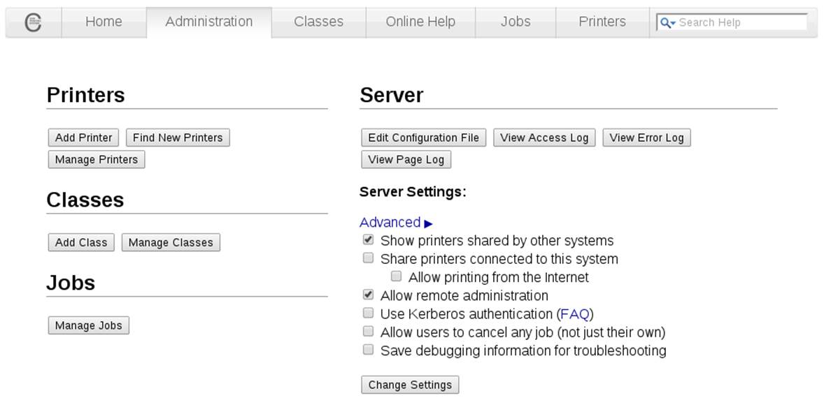
Figure 3-3. The CUPS administration web portal
Once you’ve made those edits, restart CUPS:
$ su -c 'service cups restart'
Then use a web browser to go to http://192.168.0.122:631, replacing the first part with your Pi’s IP address. (This can be on the Pi, your laptop, or any machine within the subnet.) Choose the Administration tab, and select Add Printer.
When you’re asked for a username and password, enter the information for the user you added to the lpadmin group. On the Add Printer page (Figure 3-4), choose your printer from the list under Local Printers.

Figure 3-4. The Add Printer configuration page
In the list shown in Figure 3-4, you see three printers. The two HPLIP devices are actually just printer drivers from the HP Linux Imaging and Printing project.
You’ll be asked to add or edit the name, description, and location of the printer. If you would like to, enable Share This Printer.
In the next step, you’ll be asked to choose the printer driver. You can scroll through the list until you find your printer (several are likely marked as “recommended”), or you can browse to a PPD file that you have from your printer’s manufacturer for the driver.
Finally, you’re offered the chance to set some generic print settings, like page size and source. When you’re finished setting your preferences, click Set Default Options, and you’ll be back to the main administration page for that printer.
If you haven’t already, move to another machine on the network and get it ready to print. Use that particular computer’s printer settings system (see Figure 3-5 for Fedora) to add a printer and select the one that you’ve just set up.
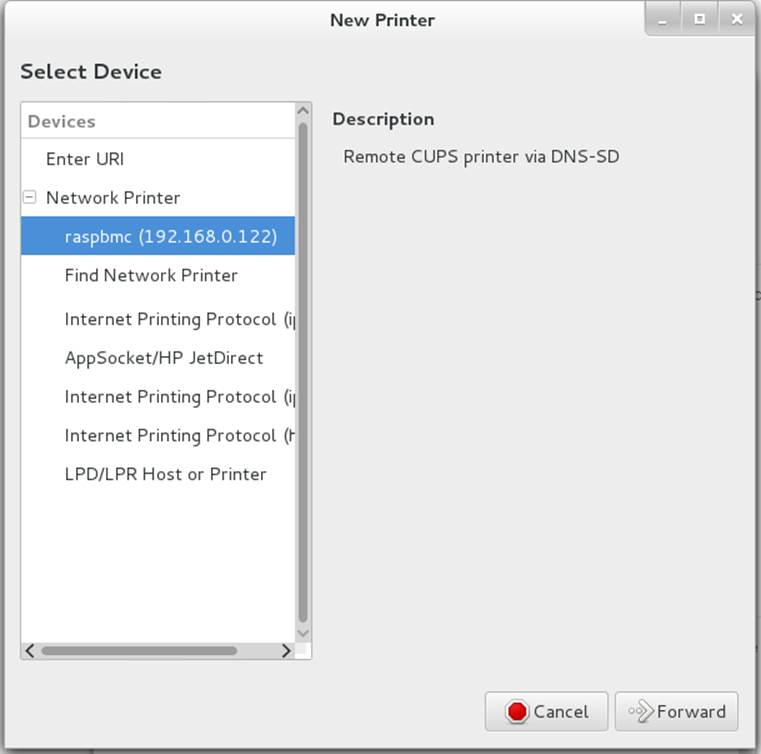
Figure 3-5. Fedora New Printer setup dialog
Print a test page, and you’re finished!
Hack 32. Make Calls with a Raspberry Pi Asterisk Telephone System
Asterisk is a telephone system in software. It is typically used to bridge callers together, or offer up features such as voicemail or call queues. Because it’s built totally in software, you can run it on your Raspberry Pi.
Because the Raspberry Pi doesn’t have any sort of analog telephone connections, setting up Asterisk means using a technology called voice over IP (VoIP) to communicate on the Raspberry Pi. You’ll use a computer program called a softphone, together with a microphone and speakers, to emulate a telephone. The softphone will then communicate across the network to Asterisk running on the Raspberry Pi.
For more information on Asterisk, check out the Asterisk website or Asterisk: The Definitive Guide from O’Reilly Media.
Installing Asterisk
Installing Asterisk is fairly simple, as most modern Linux distributions have packages rebuilt for Asterisk. On Pidora, just run the following command:
$ su -c 'yum install asterisk asterisk-voicemail-plain asterisk-sounds-core-en-gsm'
Here’s the command to run on Raspbian:
$ su -c 'aptitude install asterisk asterisk-config asterisk-core-sounds-en-gsm'
This will install Asterisk with a basic configuration, common features such as voicemail, as well as some sound prompts. Feel free to search your distribution’s package list for additional Asterisk modules.
This hack uses a VoIP protocol called SIP to communicate between one or more softphones and Asterisk. Getting SIP working through a firewall (especially a NAT firewall) is difficult and beyond the scope of this hack. In order for your connections to work, you’ll need to turn off the firewall, so that it doesn’t block connection attempts.
Don’t leave your Raspberry Pi connected to the Internet with the firewall disabled, because someone will likely attempt to try to break into your Raspberry Pi. This is especially imporant if you haven’t changed the password on your Raspberry Pi from the defaults. We suggest you turn off the firewall on your Raspberry Pi only long enough to test out things, and then turn it back on.
Starting Asterisk
Once Asterisk has been installed, you’ll need to start the Asterisk process. You can start it with the initscripts, or simply type (as root):
$ asterisk
This should start Asterisk running in the background. After Asterisk is running in the background, you can connect to the running Asterisk system with the following command:
$ asterisk -r
If for some reason Asterisk isn’t starting on your system, you can start it in console mode:
$ asterisk -c
Be aware that running it in console mode is recommended only for debugging purposes, because as soon as you exit out of the console, Asterisk stops running.
You can also increase the verbosity level of the Asterisk command prompt by supplying one or more -v arguments to Asterisk, like this:
$ asterisk -vvvr
This example sets the verbosity level to three, if it wasn’t already three or higher. At verbosity level three, Asterisk tells you about every step it executes in its dialing plan, so it’s a nice level to use when you’re learning Asterisk.
When you successfully connected to the Asterisk process, you should be greeted with a prompt that looks something like this:
Asterisk 1.8.23.1, Copyright (C) 1999 - 2013 Digium, Inc. and others.
Created by Mark Spencer <markster@digium.com>
Asterisk comes with ABSOLUTELY NO WARRANTY; type 'core show warranty' for details.
This is free software, with components licensed under the GNU General Public
License version 2 and other licenses; you are welcome to redistribute it under
certain conditions. Type 'core show license' for details.
=========================================================================
Connected to Asterisk 1.8.23.1 currently running on hockey (pid = 23801)
Verbosity was 0 and is now 3
hockey*CLI>
In this example, we’re running Asterisk version 1.8.23.1 on a computer named “hockey.”
Did you notice the last line ends in *CLI>? This is the prompt for the Asterisk command-line interface (CLI), and it is the primary tool for interacting with the Asterisk system and debugging within Asterisk. Before going any futher, here are a few commands to help you feel comfortable.
To see how long Asterisk has been running, type:
*CLI> core show uptime
hockey*CLI> core show uptime
System uptime: 55 seconds
Last reload: 55 seconds
Most commands in the Asterisk CLI follow the “subsection-verb-details” model, where the first word of the command tells which part of the system you want to interact with (core in this case, which is a verb to tell Asterisk what you’d like to do: show), and then any other details the system needs to know in order to perform the action.
To stop Asterisk immediately, type:
*CLI> core stop now
You can also use core stop when convenient to have Asterisk stop the next time there are no active calls on the system, or core stop gracefully to reject any new calls, and then shut down the system when the call volume reaches zero. Don’t shut down Asterisk just yet (unless you’d like to practice stopping it and starting it again just to get a feel for it).
The Asterisk CLI also has built-in help (type help at the CLI) and tab-completion. For an example, type help and then press the TAB key twice before --, and you’ll see that the Asterisk CLI shows you all the possibile commands that begin with “help.”
Setting Up a Softphone
There are three steps to setting up a softphone with Asterisk. The first is to configure an account within Asterisk for the phone to connect to. Second, you’ll need to configure the softphone itself to connect to Asterisk. And finally, you’ll need to set up a list of instructions (called a dialing plan or dialplan) that Asterisk should follow when a particular extension is dialed.
Configure an SIP account
To set up an account for the softphone, you’ll first need to find the configuration file for the type of connection you’ll be using. Asterisk speaks a number of different voice over IP protocols, but the most popular one is SIP, so that’s what this example will use.
To add an account for your SIP softphone, add the following lines to the very bottom of /etc/asterisk/sip.conf:
[one]
type=friend
host=dynamic
secret=cHaNgEmEpLeAsE!
context=raspi-demo
The first line (in square brackets) is the name of the account. The type line tells it what kind of a device you’re talking to. This example uses the friend type, because that means that the softphone can call Asterisk and that Asterisk can also call the softphone.
The host line says that the IP address assigned to the softphone isn’t known (or might change at any moment), so instead of hardcoding an IP address, the softphone will periodically tell Asterisk where it is. This is called registration (covered in more detail in the next section).
The secret setting is the password on this account. Pick a different password, and make it long and difficult to guess. Last, the context setting tells the system which part of the dialplan to execute when a call comes from the softphone.
Once you’ve added these lines to the sip.conf configuration file, you’ll need to tell Asterisk to reload that configuration file. From the Asterisk CLI, type:
$*CLI> sip reload
You can then use the sip show peers command to see which SIP accounts you have configured:
hockey*CLI> sip show peers
Name/username Host Dyn Forcerport ACL Port Status
one (Unspecified) D N 0 Unmonitored
1 sip peers [Monitored: 0 online, 0 offline Unmonitored: 0 online, 1 offline]
Did you notice that the host says (Unspecified)? This means that the softphone hasn’t registered with Asterisk yet, so we don’t know where to find the softphone to send messages to it. We’ll rectify that shortly.
Register your SIP client
Next, you’ll need to use a SIP softphone to be able to connect to Asterisk for testing. There are a number of free SIP softphones available. I prefer Blink for Mac and Windows, Twinkle on Linux, and CSipSimple on Android.
While configuring each of these softphones is beyond the scope of this hack, the basics are the same. Simply configure the softphone with one as the username (and auth username, if it’s required by your softphone), cHaNgEmEpLeAsE! as the password (or the new password you entered in the secret setting in sip.conf), and the IP address of your Raspberry Pi for the SIP server, registrar, domain, proxy, and/or outbound proxy settings.
Once your softphone has registered, you should be able to run sip show peers from the Asterisk CLI again and see that the Host field now shows an IP address, like this:
hockey*CLI> sip show peers
Name/username Host Dyn Forcerport ACL Port Status
one/one 192.168.55.187 D N 7060 Unmonitored
1 sip peers [Monitored: 0 online, 0 offline Unmonitored: 1 online, 0 offline]
If you’re having problems getting your softphone to register, double-check that you’ve (temporarily) disabled the firewall on the Raspberry Pi. For simplicity’s sake, you should use a softphone within the same network as your Raspberry Pi, as the SIP protocol is notoriously difficult to use when it has to pass through a firewall or router.
You can also watch the Asterisk CLI closely when the softphone attempts to register, as it will often give you useful information (such as telling you that the password provided by the softphone doesn’t match the password in the sip.conf configuration file).
Set up an extension in the dialplan
The final step is to set up one or more extensions in the dialplan to execute when that extension is dialed by the softphone. If you were to dial extension 100 on the softphone at this point, you would likely get back a 404: Extension not found error. The Asterisk CLI would report something like this:
NOTICE[24237]: chan_sip.c:23437 handle_request_invite: Call from 'one' (192.168.55.187:7060) to extension '100' rejected because extension not found in context 'raspi-demo'.
In order to make extension 100 do something a bit more useful, you need to add a new section to the /etc/asterisk/extensions.conf configuration file. This section name needs to match the context setting from our account in the sip.conf configuration file. In this case, call it [raspi-demo].
Add the following lines to the end of /etc/asterisk/extensions.conf:
[raspi-demo]
exten => 100,1,Answer()
exten => 100,2,Playback(hello-world)
exten => 100,3,Playback(tt-weasels)
exten => 100,4,Hangup()
Let’s walk through each line quickly, and then try it out. The first line (in square brackets) is the name of the context, which is an independent section of the dialplan. Extension 100 in the [raspi-demo] context is independent from extension 100 in another context, such as [not-my-demo]. Contexts are often used to keep different clients isolated from parts of the dialplan, or to provide different features to different clients.
The second line defines an extension (100, in this case) and a priority (or step number, which is 1 in this case) and says that the first thing extension 100 should do is to call the Answer() application. This application, as its name implies, answers the call.
Note that the priority numbers must be in numerical order, and should not skip any numbers. For example, if Asterisk executes priority number three and can’t find a priority number four, it will simply hang up the call for security reasons.
The next line (priority 2), calls the Playback() application, which plays a prerecorded sound file in which you’ll hear a female voice say “Hello, World.” The next line (priority 3) also plays a sound file, which tells you that “Weasels have eaten our phone system.” The last line calls the Hangup() application, which ends the call.
The parameter to the Playback() application is the name of the sound file to play, without the extension. Asterisk is smart enough to choose the best sound prompt format to play if there are multiple files with the same name but in different formats. It chooses the format that requires the least amount of CPU power to transcode (or convert) to the current audio format of the call.
Once you’ve added those five lines to the end of your extensions.conf configuration file, you’ll need to tell Asterisk to reload the dialplan. To do this, go to the Asterisk CLI and type dialplan reload.
To test that your new [raspi-demo] context has been successfully read and parsed, type:
hockey*CLI> dialplan show raspi-demo
[ Context 'raspi-demo' created by 'pbx_config' ]
'100' => 1. Answer() [pbx_config]
2. Playback(hello-world) [pbx_config]
3. Playback(tt-weasels) [pbx_config]
4. Hangup() [pbx_config]
-= 1 extension (4 priorities) in 1 context. =-
Now’s the time for the big test! From your softphone, dial 100, and listen for Asterisk to play the sound prompts.
We’re only scratching the surface with the most basic of applications here. For a full list of the dialplan applications you can use in your dialplan, type core show applications at the Asterisk CLI.
Of course, there’s much more that you can do with Asterisk on your Raspberry Pi, including implementing call menus, voicemail, allowing clients to call each other, and so forth. Now that you’ve learned the basics, you can dive into all the wonderful things that Asterisk can do. And don’t forget to turn your firewall back on when you’re done!
—Jared Smith
Hack 33. Build Your Own Web Server
From kids with creative urges to grown-ups with pet projects, wanting your own website is a common desire. Having a Raspberry Pi makes it easy to set up your own web server, whether it’s for your blog or a web interface for interacting with a larger Pi project.
There are as many reasons to want a web server as there are websites. We’ll cover two options: first, how to set up your own blog on a Raspberry Pi; second, getting started with a development environment called Coder that helps you learn the basic building blocks of the web: HTML, JavaScript, Cascading Style Sheets (CSS), and Node.JS.
Set Up a Basic Blog Server
There are hundreds of millions of blogs out there. Why not let your Pi add a voice to the chorus? The easiest way to get your Pi online and yourself blogging is by setting up the LAMP stack: Linux, Apache (web server), MySQL (database), and PHP. Together they give you a base on which you can run WordPress, one of the most popular blogging platforms.
By setting up a distro on your Pi, you already have the L down, so let’s move to the A. Here’s how to install Apache on Pidora:
$ su -c 'yum install httpd mod_ssl'
And here’s the command for Raspbian:
$ su -c 'apt-get install apache2'
The detail of possibilities for using and configuring Apache are well beyond the scope of this book, but also well documented elsewhere. We recommend starting with the online documentation. If you’re interested in a book, try Apache Cookbook (O’Reilly), or for a broader introduction to web development, Beginning PHP5, Apache, and MySQL Web Development (O’Reilly).
Next you’ll need to install MySQL, PHP, and the PHP gd module (required by WordPress). Here’s the command for Pidora:
$ su -c 'yum install mysql mysql-server'
$ su -c 'yum install php php-mysql php-gd'
And here’s the command for Raspbian:
$ su -c 'apt-get install mysql-server'
$ su -c 'apt-get install php php-mysql php-gd'
Start the MySQL daemon and Apache, on Pidora:
$ su -c 'systemctl start mysqld.service'
$ su -c 'systemctl start httpd'
or on Raspbian:
$ su -c 'service start mysqld'
Then ensure that they will both start on their own in the future, on Pidora:
$ su -c 'chkconfig mysqld on'
$ su -c 'chkconfig httpd on'
or on Raspbian:
$ su -c 'update-rc.d mysqld enable'
$ su -c 'update-rc.d httpd enable'
Then set up the installation:
$ su -c '/usr/bin/mysql_secure_installation'
You’ll be asked to set a root password and several other settings, which are well described by the script along with recommended choices. If all goes well, at the end you’ll see:
Cleaning up...
All done! If you’ve completed all of these steps, your MySQL installation should now be secure:
Thanks for using MySQL!
For WordPress, you’ll need a database and a user. Log in to MySQL using the root password you just set up:
$ mysql -u root -p
Then create your database and user. Replace piblogger with whatever you’d like your database to be named and ian with the user who will be in charge of it (and it should go without saying that mypassword is a terrible password choice that you should change):
mysql> CREATE DATABASE piblogger;
Query OK, 1 row affected (0.00 sec)
mysql> CREATE USER 'ian'@'localhost' IDENTIFIED BY 'mypassword';
Query OK, 0 rows affected (0.00 sec)
mysql> GRANT ALL PRIVILEGES ON * . * to 'ian'@'localhost';
Query OK, 0 rows affected (0.00 sec)
mysql> FLUSH PRIVILEGES;
Query OK, 0 rows affected (0.00 sec)
mysql> EXIT
Download the latest WordPress tarball from https://wordpress.org/latest.tar.gz or:
$ wget https://wordpress.org/latest.tar.gz
Extract the tarball into the public HTML folder:
$ sudo tar -xvzf latest.tar.gz -C /var/www/html
This will create a directory called wordpress in /var/www/html. Next you need to set up the config file:
$ vi /var/www/html/wordpress/wp-config-sample.php
The things you need to configure are at the top of the file, and the parts you need to fill in are in all caps:
// ** MySQL settings - You can get this info from your web host ** //
/** The name of the database for WordPress */
define('DB_NAME', 'piblogger');
/** MySQL database username */
define('DB_USER', 'ian');
/** MySQL database password */
define('DB_PASSWORD', 'mypassword');
/** MySQL hostname */
define('DB_HOST', 'localhost');
/** Database Charset to use in creating database tables. */
define('DB_CHARSET', 'utf8');
/** The Database Collate type. Don't change this if in doubt. */
define('DB_COLLATE', '');
Finally, change the name of the sample config to config.php. We like to save a copy of the sample until everything’s running properly, so for now:
$ cp /var/www/html/wordpress/wp-config-sample.php var/www/html/wordpress/wp-config.php
When your site is running as you would like, delete wp-config-sample.php.
Now, when you go to the site in a browser (by default it’s at /wordpress after a domain if you’ve registered one, or your IP address if you haven’t). It’s only a one-page setup (see Figure 3-6), after which you can add one more voice to the blogosphere.
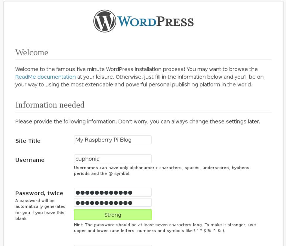
Figure 3-6. The one-page WordPress web-based setup
You can now log into your WordPress dashboard and start configuring its themes and posting. Learn more about how to use all of its features at http://codex.wordpress.org.
Use Coder for Your Website
Coder is a tool created by Jason Striegel in the Google Creative Lab as a way to teach kids basic web programming using the Raspberry Pi. It doesn’t have that kid-program feel, though, so if you’re an adult who’s never tried learning HTML, CSS, or JavaScript, it’s handy for you as well.
On the Coder website, you’ll find a ZIP file with an installer for Mac users and instructions for using it with Windows. However, there are not any instructions for using it with Linux. To do so, download the Coder ZIP file, which contains a folder (at the time of this writing, coder_v0.4) within which you’ll find two files: CoderSetup.app and raspi.img. The latter is all you need. Extract it and then use a tool like Fedora-arm-installer or dd from the command line to flash the image to your SD card:
$ sudo dd bs=4M if=raspi.img of=/dev/mmcblk0
FEDORA ARM INSTALLER
The Fedora ARM Installer is a convenient tool for flashing your SD card images if you’re less-than-comfortable with the command line. You don’t have to use it for Fedora or Pidora images; it will work with any image you want to flash to the Pi. If you’re on Fedora, you can install it with yum install fedora-arm-installer. For other systems, you can download it at http://fedoraproject.org/wiki/Fedora_ARM_Installer.
Boot the Pi with your newly flashed SD card, and you’ll see the Raspbian raspi-config screen. You don’t need to change anything, although you probably want to resize the partition (option 1, expand_rootfs). Then select Finish and reboot.
Now move back to your Linux machine and open Chrome or Chromium and go to https://coder.local in the browser. You’ll be welcomed to Coder, and all you have to do for setup is choose a password (Figure 3-7).
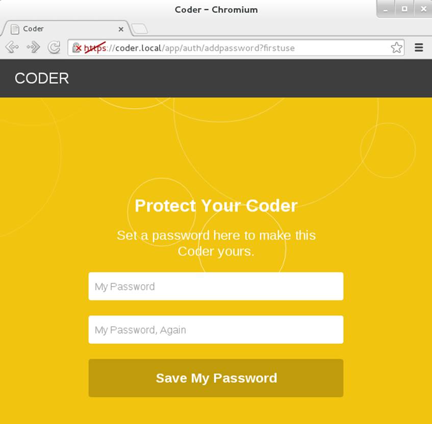
Figure 3-7. Coder setup screen
One of the first blocks you see is “Hello Coder,” which helps you explore how Coder works. The edit button is represented by the </> symbol at the upper right of the page. If you click it in Hello Coder, you find pages that give you a brief introduction to HTML, CSS, JavaScript, and Node.JS through tabs across the top of the screen.
Coder also offers two prebuilt apps, Space Rocks! and Eyeball, whose code you can explore and edit to see how they were built (which is perhaps the best way to learn how code works). You see their blocks on the home page when you start as well.
Once you enter one of these, you have two choices in the upper-right menu. You can click HACK to quickly edit a few settings to see how they affect the app (see Figure 3-8). You can also click the Coder edit button (</>) to edit all of the code behind them. In either case, you see the code on the left and the results on the right each time you click the Save button.
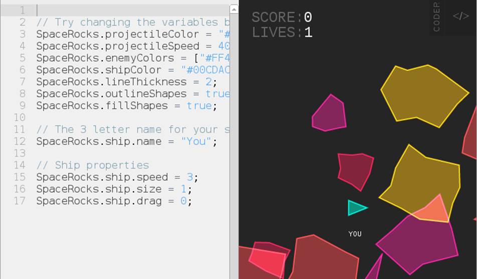
Figure 3-8. The Space Rocks! HACK screen
Finally, when you’re ready to go on your own, you click the green rectangle on the Coder homepage with a + sign in the middle and start creating your own app by naming it and giving it a color for its block on your Coder homepage. Once you’ve created it, at first all you’ll see is a basic web page. Click the Coder edit button (</>) in the upper right to start creating from scratch (Figure 3-9).
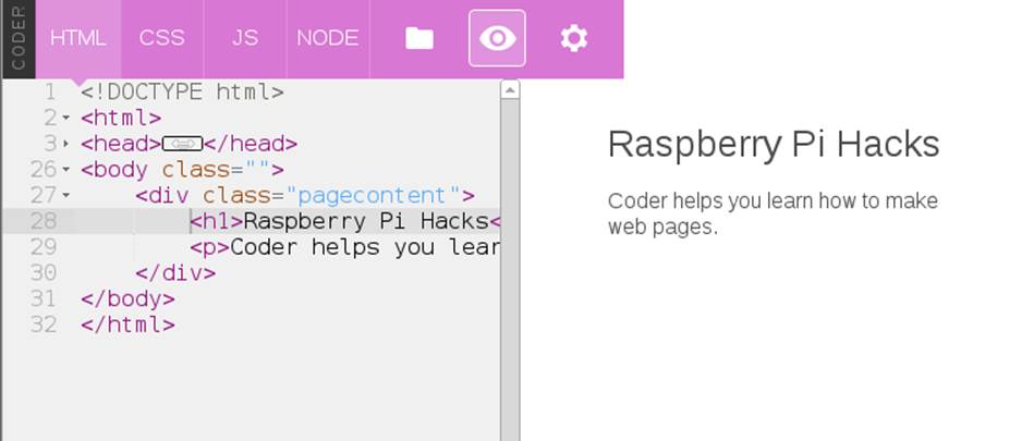
Figure 3-9. Creating your own web page and apps in Coder
You can click the small, vertical word CODER at the top of any screen to return to the home page and edit or create more apps.
Hack 34. Control a LEGO Robot
What could be cooler than a functioning, programmable robot made from LEGO bricks? A functioning, programmable LEGO robot connected to and controlled by a Raspberry Pi.
We love LEGO. Possibly more than our kids do (or ever will). We’ve also been fans of the LEGO Mindstorms kits for a long time. The LEGO Mindstorms kits are a combination of LEGO (and Technic-style) bricks and electronic components such as sensors, motors, and a programmable brick.
The brick is especially notable because it is the “brain” of the Mindstorms set, and you can program it directly to control the peripheral devices in the kit. The brick in the most recent version of the LEGO Mindstorms (LEGO Mindstorms NXT 2.0, as of this writing) is, unsurprisingly, called the NXT Intelligent Brick, and it’s pretty cool (see Figure 3-10).
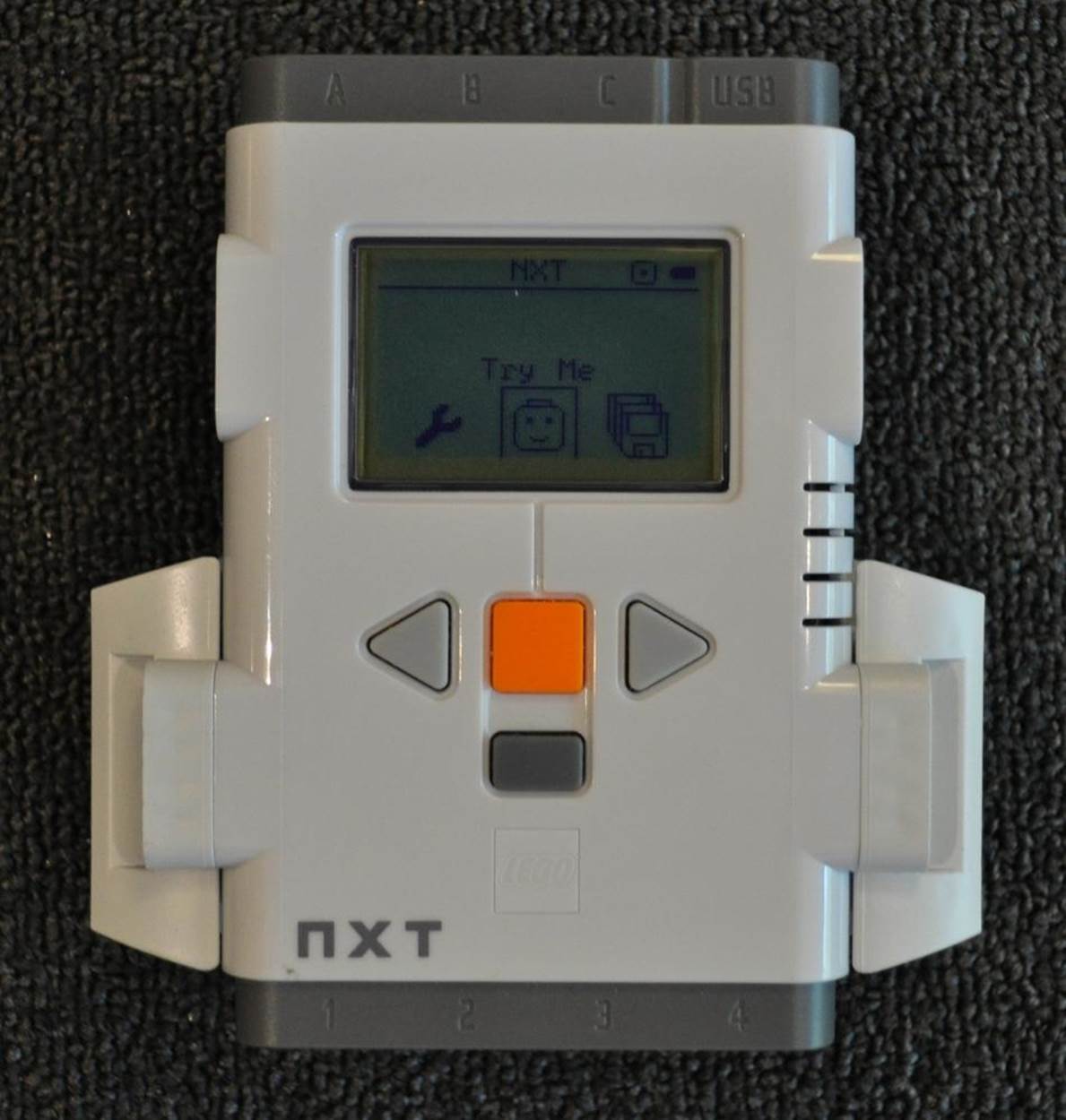
Figure 3-10. NXT Intelligent Brick
At its core, the NXT Intelligent Brick is powered by a 32-bit Atmel AT91SAM7S256 microcontroller (with 256 KB flash memory and 64 KB RAM) and an 8-bit Atmel ATmega48 microcontroller running at 4 MHz. It has an embedded 100x64 pixel LCD screen (controlled by push buttons below it) with support for four input devices (ports 1–4) and three output devices (ports A–C).
It also supports both Bluetooth and USB connections, which is important because, while you can program the brick itself to operate the attached devices for the robot (with simple programs), you can also control the brick directly via USB, and that is exactly how you’ll do it in this hack.
The LEGO Mindstorms NXT 2.0 kit comes with a lot of Windows software to control and program the brick, and there are some official (and unofficial) bindings for a wide array of languages. The official Windows software will obviously not run on a Raspberry Pi, but there is a software suite that does: ROS.
Installing ROS and Dependencies
ROS (short for robot operating system) is an open source suite of software that provides libraries and tools to help software developers create robot-related applications, including hardware abstraction, device drivers, libraries, visualizers, message-passing, and package management. It was originally developed by the Stanford Artificial Intelligence Laboratory, but that work has spun off into a company called Willow Garage, a robotics research institute and incubator. The goal is to provide a level of open source standardization on the application programming interface (API) for robotics so that a consistent set of software can be used on any type of robotic component with minimal new software necessary and the common functionality shared.
This is a thriving effort with an active community that regularly puts out major, named releases. We’ll start by installing the current stable release, as of the time of this writing: Groovy Galapagos (Groovy, for short).
NXT INTELLIGENT BRICK FIRMWARE
The ROS nxt component software requires the NXT Intelligent Brick to be running a recent version of the default LEGO firmware (v1.28 or newer). To do this, you’ll need to have a Windows (or OS X) system with the LEGO Mindstorms software installed and the NXT Intelligent Brick connected. Run the software, and go into the Tools → Update NXT Firmware menu option. You might need to download the NXT firmware files manually.
There is also a way to flash the NXT firmware from Linux. Download and install libnxt and use the fwflash executable.
Start with a clean installation of Raspbian.
There are two ways to install ROS: from prebuilt binary packages or from source. While it is certainly possible to install ROS from source on a Raspberry Pi, it takes far too long. Instead, using a community repository of ROS packages optimized for the Raspberry Pi will significantly speed up the time it takes to install ROS. To enable this APT repository of packages (called ROSpbian), run:
$ sudo echo "deb http://64.91.227.57/repos/rospbian wheezy main" > /etc/apt/sources.list.d/rospbian.list
Then add the package signing key (for package verification) and reload the apt package data:
$ wget http://64.91.227.57/repos/rospbian.key -O - | sudo apt-key add -
--2013-08-27 19:31:41-- http://64.91.227.57/repos/rospbian.key
Connecting to 64.91.227.57:80... connected.
HTTP request sent, awaiting response... 200 OK
Length: 1739 (1.7K) [application/pgp-keys]
Saving to: `STDOUT'
100%[============================================================================================================>] 1,739 --.-K/s in 0s
2013-08-27 19:31:41 (20.2 MB/s) - written to stdout [1739/1739]
OK
$ sudo apt-get update
Now you can install ROS packages from the ROSpbian repository. The ros_comm components are a good starter package, because they will pull in all of the core ROS components and tools as dependencies and install everything in one pass:
$ sudo apt-get install ros-groovy-ros-comm ros-groovy-rosbuild
It will take a little while to complete. When it finishes, you’ll need to configure your user account to enable the ROS environment by default. ROS includes a bash script containing a number of environment variables (and amendments to $PATH) so that you can run ROS commands. Make sure your account sources this file (in bash, source is roughly analogous to using #include in a C program).
To source the ROM environment every time you log in (or instantiate a bash shell), you need to add it to the .bashrc file in that user’s home directory:
$ echo "source /opt/ros/groovy/setup.bash" >> ~/.bashrc
You also want root to be aware of the ROS environment, so do the same for the root user. Use sudo and su - together to switch to a root user session, then run the command again to source /opt/ros/groovy/setup.bash during .bashrc:
$ sudo su -
$ echo "source /opt/ros/groovy/setup.bash" >> /root/.bashrc
$ exit
Now you’re ready to download and prepare the ROS components for the NXT Mindstorms. As mentioned before, the ROS software provides a framework of standardized components, but each specific robotic device needs a module (or modules) to support its specific quirks. NXT Mindstorms requires the nxt family of modules. Max Sieber forked off a copy of the nxt codebase to add support for the Groovy ROS and the Raspberry Pi, but it needed some additional patches to build properly. We’ve forked a copy of his work and added fixes. Clone a copy of our GitHub repository to work with:
$ sudo apt-get install git
$ git clone https://github.com/spotrh/nxt
ROS is very, very picky about where its files live on the filesystem, so you need to move your nxt checkout to the proper location:
$ sudo mv nxt /opt/ros/groovy/share/
If you do not move the nxt “stack” into that ROS directory, none of the ROS tools will find it.
You’ll need to set up Raspbian to give permission for the pi user to communicate with the NXT Intelligent Brick as a normal user (rather than using root). To do this, start by adding the lego group:
$ sudo groupadd lego
Then add yourself to that group:
$ sudo usermod -a -G lego <username>
The value for <username> is either the default pi username in Raspbian or a custom user, if you have created one.
Next, set up udev rules to allow any users in the lego group to have read/write access to the NXT Intelligent Brick. The nxt/70-lego.rules file contains prewritten rules, so you just need to copy it into the udev rules directory:
$ sudo cp -a nxt/70-lego.rules /etc/udev/rules.d/70-lego.rules
Then restart udev to make the new rules take effect:
$ sudo service udev restart
LOCALE HANDLING IN RASPBIAN
Raspbian defaults to a locale setting of en_GB.UTF-8. You might encounter weird errors if you’re actually trying to communicate from en_US.UTF-8 (or any other UTF-8 locale that isn’t en_GB). ROS does this sometimes. Specifically, this sort of thing:
terminate called after throwing an instance of 'std::runtime_error'
what(): locale::facet::_S_create_c_locale name not valid
Aborted
This error is caused because the en_US.UTF-8 (or other requested) locale does not exist. The easiest way to fix this is by running dpkg-reconfigure:
$ sudo dpkg-reconfigure locales
This loads a text interface to configure additional locales on Raspbian. Either select “All locales” (this will eat up some disk space), or scroll down with the arrow keys and select en_US.UTF-8 UTF-8 (or any other locales relevant to you). On the next screen, set the proper default language/locale for you. It will regenerate the locale files, reset the LC_* environment variables, and resolve this issue.
Normally, you’d build your ROS stack here, but it is worth noting that ROS is migrating away from stacks. The ROS NXT code is still configured to use stacks, as opposed to using catkin, which is the tool that most of the Groovy ROS prefers. As a result, you’ll need to install some additional nxt dependencies manually (it doesn’t help that the ROSpbian repository is missing a lot of catkinized components, too):
$ sudo apt-get install ros-groovy-geometry-msgs ros-groovy-nav-msgs ros-groovy-sensor-msgs \
ros-groovy-visualization-msgs ros-groovy-tf ros-groovy-image-transport ros-groovy-laser-geometry \
ros-groovy-python-qt-binding ros-groovy-urdfdom ros-groovy-rosconsole-bridge ros-groovy-image-geometry \
libcurl4-openssl-dev libxml2-dev ros-groovy-geometric-shapes libassimp-dev ros-groovy-orocos-kdl \
libogre-dev libyaml-cpp-dev python-wxgtk2.8 wx2.8-headers libwxgtk2.8-dev ros-groovy-tf-conversions \
python-usb ros-groovy-python-orocos-kdl
This will take a few minutes to complete.
Next, you’ll need to build collada-dom from source. The COLLADA Document Object Model (DOM) is an API that provides a C++ object representation of a COLLADA XML instance document. The COLLADA format is used for interactive 3D applications, and ROS uses it.
Download and unpack a copy of the collada-dom source tarball from SourceForge:
$ sudo mkdir /opt/ros/collada
$ cd /opt/ros/collada
$ sudo wget http://downloads.sourceforge.net/project/collada-dom/Collada%20DOM/Collada%20DOM%202.4/collada-dom-2.4.0.tgz
$ sudo tar xf collada-dom-2.4.0.tgz
Make a build directory within the source directory and build and install the collada-dom code:
$ cd collada-dom-2.4.0
$ sudo mkdir build
$ cd build
$ sudo cmake ..
$ sudo make
$ sudo make install
That will take several hours to build on the Raspberry Pi. Once it has finished, you need to build a newer version of assimp.
Assimp is the library short name for the Open Asset Import Library, which provides support for a variety of 3D file formats. You might have noticed that you installed libassimp-dev as a dependency, but the version packaged in Raspbian does not work properly with the collada code in ROS. Never fear, you just need to build a newer version from source code to replace it (you still want to install the libassimp-dev package, to keep all the dpkg dependencies are happy):
$ cd ~
$ git clone https://github.com/assimp/assimp
Cloning into 'assimp'...
remote: Counting objects: 17035, done.
remote: Compressing objects: 100% (4368/4368), done.
remote: Total 17035 (delta 12579), reused 16717 (delta 12293)
Receiving objects: 100% (17035/17035), 60.56 MiB | 594 KiB/s, done.
Resolving deltas: 100% (12579/12579), done.
Checking out files: 100% (1646/1646), done.
Once you have the assimp source code handy, you just need to build it and install it (into the system paths, not /usr/local). You also need to explicitly delete the packaged assimp libraries before installing the newer assimp version:
$ sudo rm -rf /usr/lib/libassimp*
$ mkdir build
$ cd build
$ cmake -DCMAKE_INSTALL_PREFIX:PATH=/usr ..
$ make
$ sudo make install
This will completely overwrite the assimp files from the Raspbian package with the newer ones that work with the ROS collada code.
If Raspbian updates libassimp3 and does not have the fix for ROS collada, you might undo this work by applying that update.
At this point, you should have collada-dom and a working assimp installed. Now, manually build the catkinized ROS components that are not yet in ROSpbian. To build catkinized ROS components, create a catkin workspace to use:
$ mkdir -p ~/catkin_ws/src
$ cd ~/catkin_ws/src
$ catkin_init_workspace
Download the urdf component source into the catkin workspace (it is part of the robot_model component) with a git checkout into catkin_ws/src/:
$ git clone https://github.com/ros/robot_model.git
Cloning into 'robot_model'...
remote: Counting objects: 4176, done.
remote: Compressing objects: 100% (1715/1715), done.
remote: Total 4176 (delta 2257), reused 4141 (delta 2232)
Receiving objects: 100% (4176/4176), 2.16 MiB | 418 KiB/s, done.
Resolving deltas: 100% (2257/2257), done.
GitHub repositories for fast-moving projects like ROS often support multiple branches at once, so it is important to make sure you have the correct branch for the version of ROS you are using. In this case, you are using groovy, so you need to change yourrobot_model checkout to reflect the groovy-devel code branch:
$ cd robot_model
$ git checkout groovy-devel
Branch groovy-devel set up to track remote branch groovy-devel from origin.
Switched to a new branch 'groovy-devel'
$ cd ..
Manually download the map_msgs component in the same method and directory (catkin_ws/src) as for urdf:
$ git clone https://github.com/ethz-asl/map_msgs
Cloning into 'map_msgs'...
remote: Counting objects: 43, done.
remote: Compressing objects: 100% (27/27), done.
remote: Total 43 (delta 12), reused 43 (delta 12)
Unpacking objects: 100% (43/43), done.
Download the next component (cmake_modules), needed to build ROS COLLADA support:
$ git clone https://github.com/ros/cmake_modules
Cloning into 'cmake_modules'...
remote: Counting objects: 125, done.
remote: Compressing objects: 100% (61/61), done.
remote: Total 125 (delta 60), reused 119 (delta 58)
Receiving objects: 100% (125/125), 17.46 KiB, done.
Resolving deltas: 100% (60/60), done.
Download the interactive_markers component:
$ git clone https://github.com/ros-visualization/interactive_markers
Cloning into 'interactive_markers'...
remote: Counting objects: 10659, done.
remote: Compressing objects: 100% (5209/5209), done.
remote: Total 10659 (delta 5297), reused 10484 (delta 5138)
Receiving objects: 100% (10659/10659), 7.90 MiB | 976 KiB/s, done.
Resolving deltas: 100% (5297/5297), done.
$ cd interactive_markers
$ git checkout groovy-devel
Branch groovy-devel set up to track remote branch groovy-devel from origin.
Switched to a new branch 'groovy-devel'
$ cd ..
While a package for this exists in ROSpbian, it is not current enough. Be sure to switch this to the groovy-devel branch as well (it may or may not already be on this branch when you check it out).
Last, but not least, download the source tree for the rviz component and switch the code checkout to use the groovy-devel branch:
$ git clone https://github.com/ros-visualization/rviz
Cloning into 'rviz'...
remote: Counting objects: 14175, done.
remote: Compressing objects: 100% (6144/6144), done.
remote: Total 14175 (delta 8853), reused 13288 (delta 7980)
Receiving objects: 100% (14175/14175), 11.31 MiB | 820 KiB/s, done.
Resolving deltas: 100% (8853/8853), done.
$ cd rviz
$ git checkout groovy-devel
Branch groovy-devel set up to track remote branch groovy-devel from origin.
Switched to a new branch 'groovy-devel'
$ cd ..
Go back to the top-level directory of your catkin workspace and run catkin_make:
$ cd ~/catkin_ws
$ catkin_make -DCMAKE_INSTALL_PREFIX=/opt/ros/groovy
The catkin_make command is a sort of “super cmake“: it orders all of the components in the catkin workspace, then iterates through them, configuring each of them in order and then building them in order.
The -DCMAKE_INSTALL_PREFIX flag tells catkin_make that you want to install your files into /opt/ros/groovy. You will start to see output from catkin_make immediately, but it will take a long time to successfully complete. The output provides a percentage progress indicator to let you know how far along the build process is:
[ 26%] Building CXX object rviz/src/rviz/CMakeFiles/rviz.dir/tool_manager.cpp.o
[ 26%] Building CXX object rviz/src/rviz/CMakeFiles/rviz.dir/uniform_string_stream.cpp.o
[ 27%] Building CXX object rviz/src/rviz/CMakeFiles/rviz.dir/view_controller.cpp.o
This is going to take a few hours to complete (we just left it building overnight and came back to it in the morning). When it finishes, it should look something like this (ignore the warnings; like Earth, they’re mostly harmless):
{standard input}:10893: Warning: swp{b} use is deprecated for this architecture
[100%] Meta target for rviz_sip Python bindings...
[100%] Built target librviz_sip
You also need to use catkin_make to install these files into the /opt/ros/groovy ROS structure, but because you need to run this as root, you have to take a few extra steps (you can’t just use sudo). Just switch to a root session with sudo and su -, then change back into your catkin workspace directory (/home/pi/catkin_ws). Once there, run catkin_make install, with the CMAKE_INSTALL_PREFIX definition set to /opt/ros/groovy:
$ sudo su -
$ cd /home/pi/catkin_ws
$ sudo catkin_make install -DCMAKE_INSTALL_PREFIX=/opt/ros/groovy
$ exit
That should not take long to complete, but now you have all of your catkinized ROS components ready and installed. Now you build the legacy ROS stacks (including the NXT stack that you need to use):
$ cd ~
$ rosmake -i nxt
The -i flag tells rosmake to mark components hatbuild successfully with the ROS_NOBUILD flag, which keeps rosmake from building things over and over later without any good reason.
The rosmake build process generates a lot of output, but most of it isn’t terribly useful. It will attempt to build all the components in the nxt stack, along with the dependencies you’ve downloaded. You can see that rosmake is iterating through all the catkinizedcomponents and looking for its build files (and not finding them), which is where most of the noisy output comes from. It should finish with output that looks something like this:
[ rosmake ] Results:
[ rosmake ] Built 66 packages with 0 failures.
[ rosmake ] Summary output to directory
[ rosmake ] /home/pi/.ros/rosmake/rosmake_output-20130909-141408
At this point, you should have an installation on your Raspberry Pi that contains the core ROS stack and the additional ROS components necessary to support the NXT Mindstorms brick and sensors. If you’ve made it this far, you should be proud. While ROS is an awesome toolkit, installing it for the Raspberry Pi is no easy task at the moment.
Testing the ROS Connection to the NXT Brick
It’s time to make sure that ROS can see the NXT Intelligent Brick. Make sure your brick has fresh batteries (or an AC adapter plugged in), and power it on (the orange button in the center is the power button). Connect the USB cable from the NXT Brick to the Raspberry Pi. (Feel free to put a powered USB hub in the middle.)
Get out one of the touch sensors from the NXT Mindstorms kit. This sensor is used by the kit to indicate when your robot runs into something (and thus “touches” it). It has an orange button on its tip that you can easily press in with your finger. Connect the touch sensor to Port 1 (lower left of the NXT brick).
Then open two sessions to the Raspberry Pi (either terminals if you are running locally, or SSH sessions if not—see [Hack #12] for help). In the first session, you’re going to start roscore, the heart of ROS. It provides support for the nodes that allow the ROS infrastructure to function. You can start it manually to test your connection by running roscore, which should result in output that looks like the following:
$ roscore
... logging to /home/pi/.ros/log/bffc809a-1957-11e3-b0b1-b827eb545e36/roslaunch-raspberrypi-12155.log
Checking log directory for disk usage. This may take awhile.
Press Ctrl-C to interrupt
Done checking log file disk usage. Usage is <1GB.
started roslaunch server http://raspberrypi:44402/
ros_comm version 1.9.41
SUMMARY
========
PARAMETERS
* /rosdistro
* /rosversion
NODES
auto-starting new master
process[master]: started with pid [12174]
ROS_MASTER_URI=http://raspberrypi:11311/
setting /run_id to bffc809a-1957-11e3-b0b1-b827eb545e36
process[rosout-1]: started with pid [12187]
started core service [/rosout]
At this point, the session will stop (although roscore is still running), and ROS will be ready to run tasks. Switch to your second session or terminal.
In this session, you need to be root to access the USB device, so go ahead and use sudo and su - to switch to a root session. Then you can use the rosrun command to run a ROS Python script to check the touch sensor. This script is simple; it polls the sensor and prints True or False for the state of the touch sensor. “True” means it is touching something; “False” means it is not.
It will time out after a few seconds, so have the sensor handy, and then run:
$ sudo su -
$ rosrun nxt_python touch_sensor_test.py
As you press the sensor, your screen should scroll messages indicating the sensor state, like this:
TOUCH: False
TOUCH: True
For good measure, let’s test the color sensor as well (using color_sensor_test.py from the nxt_python component). The color sensor can emit a range of colors from its LED and can also detect the color and intensity of objects in front of it. Plug it into Port 1 (unplug the touch sensor) and run (as root):
$ rosrun nxt_python color_sensor_test.py
This will flash the LED on the front of the color sensor to red, blue, green, white, and then off. Next, it will take intensity readings for the amount of “blue” light (try covering the sensor completely to watch it drop to zero). Finally, it will detect the color in front of the sensor and return a decimal value corresponding to the color codes in Table 3-1.
Table 3-1. NXT RGB color sensor detected values
|
Number |
Color |
|
1 |
Black |
|
2 |
Blue |
|
3 |
Green |
|
4 |
Yellow |
|
5 |
Red |
|
6 |
White |
Pretty nifty, huh? Go ahead and disconnect the color sensor, as it might be left on after the test script completes, and you don’t want to burn it out.
Now that you know that the ROS environment is working with the NXT Intelligent Brick, you can build a test robot model. There are a few different ways to do this, but the simplest is to create a new ROS package and modify it.
First, use the roscmd tool to change into the nxt component directory, and then create a new ROS package called my_nxt_robot with the aptly named roscreate-pkg command (you do not need to be root):
$ roscd nxt
$ roscreate-pkg my_nxt_robot rospy nxt_ros
Created package directory /opt/ros/groovy/share/nxt/my_nxt_robot
Created python source directory /opt/ros/groovy/share/nxt/my_nxt_robot/src
Created package file /opt/ros/groovy/share/nxt/my_nxt_robot/Makefile
Created package file /opt/ros/groovy/share/nxt/my_nxt_robot/manifest.xml
Created package file /opt/ros/groovy/share/nxt/my_nxt_robot/CMakeLists.txt
Created package file /opt/ros/groovy/share/nxt/my_nxt_robot/mainpage.dox
Please edit my_nxt_robot/manifest.xml and mainpage.dox to finish creating your package
This command also tells roscreate_pkg that your new my_nxt_robot ROS package will depend on rospy and nxt_ros.
Now, prepare the new my_nxt_robot ROS package with rosmake and change into the directory:
$ rosmake
$ cd my_nxt_robot
You need to write out a configuration file, which will tell the NXT ROS bindings what you have connected to the NXT Intelligent Brick. Open a file editor and save out the following as robot.yaml:
nxt_robot:
- type: touch
frame_id: touch_frame
name: my_touch_sensor
port: PORT_1
desired_frequency: 20.0
This configuration says that you have a touch sensor connected on Port 1 (named my_touch_sensor) that you wish to check the status of 20 times per second (or 20 Hz). The NXT brick is not capable of handling high check frequencies, so you probably don’t want to set this value any larger (smaller is fine, though). Go ahead and reconnect the touch sensor to Port 1 (and make sure your NXT brick is powered on).
Each device connected to the brick should be specified in this file, starting with a - before the type definition. For this example, we’re keeping it simple, but when you want to build a more complicated robot, you’ll need more than one item in this file.
To get ROS to run the robot, you need to create a ROS launch file named robot.launch. Using a text editor, create a new file with that name and add the following inside it:
<launch>
<node pkg="nxt_ros" type="nxt_ros.py" name="nxt_ros" output="screen" respawn="true">
<rosparam command="load" file="$(find my_nxt_robot)/robot.yaml" />
</node>
</launch>
Now you can test your simple, one-sensor robot. You must be root, so switch to a root session first, change back into the my_nxt_robot package directory, and then use roslaunch to launch the ROS robot:
$ sudo su -
$ roscd my_nxt_robot
$ roslaunch robot.launch
... logging to /root/.ros/log/bffc809a-1957-11e3-b0b1-b827eb545e36/roslaunch-raspberrypi-20985.log
Checking log directory for disk usage. This may take awhile.
Press Ctrl-C to interrupt
Done checking log file disk usage. Usage is <1GB.
started roslaunch server http://raspberrypi:43572/
SUMMARY
========
PARAMETERS
* /nxt_ros/nxt_robot
* /rosdistro
* /rosversion
NODES
/
nxt_ros (nxt_ros/nxt_ros.py)
ROS_MASTER_URI=http://localhost:11311
core service [/rosout] found
process[nxt_ros-1]: started with pid [21027]
[INFO] [WallTime: 1378757674.921416] Creating touch with name my_touch_sensor on PORT_1
You should see output similar to these messages, which indicate that ROS is running your robot. It will not return you to a shell prompt and will run in that session until you kill it (Ctrl+C will do the trick). Go ahead and open a second session to your Raspberry Pi.
This robot configuration defines one sensor: my_touch_sensor. You can confirm that this touch sensor is active by running the rostopic list command:
$ rostopic list
/my_touch_sensor
/rosout
/rosout_agg
You can see the raw output from the touch sensor by running rostopic echo my_touch_sensor. This will stream a running status to your terminal as the headers come in from the touch sensor. Press and hold the touch sensor and note that the contact field changes from False to True:
header:
seq: 2088
stamp:
secs: 1378758120
nsecs: 589009046
frame_id: touch_frame
contact: True
If you want to add a servo motor (connected to output Port A), you could add a section like this to your robot.yaml:
- type: motor
name: l_motor_joint
port: PORT_A
desired_frequency: 10.0
In this example, we’ve defined a motor as a “joint,” which makes sense in the context of a LEGO Mindstorms robot. The motor turns, and it makes the robot flex at that point. Because we’ve added a joint, we also need to tell ROS to aggregate the joint states in ourrobot.launch file. Edit that file so that it now looks like this:
<launch>
<node pkg="nxt_ros" type="nxt_ros.py" name="nxt_ros" output="screen" respawn="true">
<rosparam command="load" file="$(find my_nxt_robot)/robot.yaml" />
</node>
<node pkg="nxt_ros" type="joint_states_aggregator.py" name="joint_state_publisher" output="screen" />
</launch>
By adding sensors and output motors, you have the building blocks of an ROS robot. The ROS framework is incredibly powerful, but also very complicated.
Unfortunately, going into details on building more complicated robots in ROS would be a whole book unto itself! In fact, there has been at least one published so far. There is a lot of documentation on how to use ROS, and the ROS community is generally very helpful to newcomers, which will help you get to the next step of the robot of your imagination.
Just Python, Please
ROS is very cool, but if you just want to build a simple Mindstorms robot, you can use a set of NXT Python bindings without the complexity of ROS.
Raspbian has a python-nxt package that you can install via apt-get:
$ sudo apt-get install python-nxt
This code is similar to the ROS nxt_python component, but it is much newer and does not depend on ROS. The python-nxt component includes a simple sensors test case. Connect a touch sensor to Port 1, a sound sensor to Port 2, a light sensor to Port 3, and an ultrasonic sensor to Port 4. Then run the test code (as root):
$ sudo python /usr/share/doc/python-nxt/examples/test_sensors.py
Touch: False
Sound: 0
Light: 0
Ultrasonic: 22
If ROS is still running, this might give you an error about not being able to access the NXT Intelligent Brick (only one application at a time can talk to the NXT Brick). Kill any running ROS processes and try again.
Obviously, your own readings will vary from these examples. Another example in /usr/share/doc/python-nxt/examples/spin.py shows how you can trigger motors attached to the NXT Intelligent Brick output ports. This code is short, so we will walk through it here:
#!/usr/bin/env python
import nxt.locator
from nxt.motor import *
The first line tells the shell that this is a Python program and needs to be run through the Python interpreter when executed directly. The next two lines import the specific functions from the python-nxt library that the script is using, the nxt.locator function that finds and connects to the NXT brick, and all of the nxt.motor functions.
This section defines the spin_around function:
def spin_around(b):
m_left = Motor(b, PORT_B)
m_left.turn(100, 360)
m_right = Motor(b, PORT_C)
m_right.turn(-100, 360)
It creates the m_left variable, which is mapped to the motor connected to the brick’s output Port B, and the m_right variable, which is mapped to the motor connected to output Port C. It then tells m_left to do a 360° turn with 100 power units (the possible range is from -127 to 128, and the python-nxt code recommends that you have an absolute value greater than 64). Next, it tells m_right to do a 360° turn at -100 power. In other words, this function does exactly what it says: it uses the motors to spin the robot around.
This last part of the code finds the NXT Intelligent Brick and assigns it to the b variable, then tells that brick to spin_around:
b = nxt.locator.find_one_brick()
spin_around(b)
Try not to get too dizzy.
There are other good examples of using python-nxt in /usr/share/doc/python-nxt/examples/, as well as on the python-nxt website.
Hack 35. (Appear to) Survive a Gaping Chest Wound
The Raspberry Pi isn’t bulletproof. It won’t actually save you from looking like an extra on a crime show. But you can take your video-game armor costume to the next level with a Pi, its camera, and a small screen.
Cosplay (short for costume play), has boomed in the last few years. Even if you haven’t considered costuming much since your mom dressed you as a pumpkin for the second-grade Halloween play, you’ve probably seen some of these amazing works online from events like the Comic Con and Dragon Con fan conventions or on shows like SyFy’s Heroes of Cosplay.
Build the Costume
One area in particular that has taken off is armor building. It sounds like something you’d need welding skills for, but you might be surprised what the best way to pull of a realistic, inexpensive armor costume is: foam. Simple sheets of foam.
This could mean a couple of different things, starting with the thin craft foam you find at your local craft supply store, usually in 12” x 18” sheets alongside buckets of adhesive foam cutout shapes for kids to make cheesy craft projects at summer camp. This type of foam is great for areas that need to look or be thin, like finger pieces, or for detail work.
At the other end of the spectrum, you can purchase pieces of EVA foam up to an inch thick or more. The easiest way to obtain this is to go to a hardware supply store (we find it at Harbor Freight Tools, which has locations all over the United States) and look for interlocking foam floor mats. The ones Harbor Freight sells come in a pack of four (and are often on sale!) with a smooth side and a textured side that looks great for certain types of armor.
OTHER MATERIALS FOR ARMOR BUILDING
Foam isn’t the only way to go. When you’re ready to graduate to the next level, it’s time to learn how to build with fiberglass. Before fiberglass, there were thermoplastics. If you bought craft store plastic in the ’80s, heated it up in a pot of water, and molded it into strange shapes and earrings, that’s what we’re talking about (products like Friendly Plastic and Wonderflex). The currently popular version is called Worbla. It’s easy to cut, takes paint well, and you can use all the scraps by heating it up and balling it up like clay. Creative costumers have even used plastic garbage cans. Or if you’re just not ready for the investment, there’s always the pile of cardboard boxes in your garage. Don’t scoff. The Dragon Con 2013 Masquerade winner was a pretty great cardboard RoboCop.
The fabric store doesn’t sell armor patterns alongside the sewing patterns, though, so you’re going to have to look elsewhere. Pepakura to your rescue! Pepakura is the Japanese word for “papercraft,” as well as the name of a piece of software for creating 3D paper models. If you expand one of those models to be human-sized, you have a pattern for making your armor. Unfortunately, the software is Windows-only, but it’s worth it to get your armor made.
You can create your own 3D models in software like Blender, but if you want to make a costume of a fairly well-known character like Iron Man or Commander Shepard from Mass Effect, you can find patterns freely available online from someone else who did it first. Just search for “pepakura [costume name].” There is also a handy Instructables tutorial to get you started.
RESOURCES FOR COSTUME BUILDING
If you’re interested in general costume building, the first place you should go is the forums on The Replica Prop Forum. Other groups exist for specific interest groups, such as the 405th Infantry Division for Halo and the 501st Legion for people interested in joining others with Star Wars costumes for the Imperial side. (Those on the “good guy” side should check out the Rebel Legion.)
Once you get involved with all of this, you’ll find that unless you’ve done a particularly spectacular job or something incredibly creative, your costume armor is just another in a sea of the same character. For example, more than 60 people showed up to the Mass Effect photo shoot at Dragon Con in 2013. That’s a lot of Sheps, and that’s just the ones who showed up for the shoot!
Even if you create an original design, it’ll look like Just More Armor to all the people who think it looks cool but would totally believe you if you told them Big Daddy was this guy in the Brotherhood of Steel from Half-Life, which was this really dark spinoff of Super Mario Brothers. (You should play it!) What you need is something just a little bit different.
Add the Battle Wound
Enter your battle wound. The goal is to hide the tiny camera in one side of your armor with the screen in the opposite side, flush with the armor. With an image of what’s behind you showing in front on the screen, the effect is that someone can see through you. You might remember some news stories from around the time the third Harry Potter film was released about a “real invisibility cloak.” This is a far, far cruder version of the camera-and-screen technique used to make that cloak.
RESOLUTION, PARALLAX, DETAILS, DETAILS…
Understand that this is not a perfect effect. Though it’s going to look awesome in a still photo in the right pose, someone standing close to you will clearly see that this is a screen. A tiny TFT LCD has pretty good resolution, but few screens (especially any you can afford to embed in a costume) have lifelike resolution. On top of that, there’s the matter of parallax. Imagine a hole in a wall. (OK, we often call those “windows,” but we’re talking armor here, so imagine you just blasted a hole in the wall with your massive fictional weapon that goes “pew pew pew.”) As you walk past the window or stand and sit in front of it, what you see changes. What a viewer sees through your chest screen will change only when you or the background move.
For this project, you’ll need a TFT like the one in [Hack #57] (or other small screen), a Raspberry Pi camera, and your armor-building (a.k.a. foam-destroying) tools. If you get this far in the project, you’ll have discovered that it’s a lot easier to cut the foam, particularly the thick kind, with a hot knife. You can get kits that include a hot blade, such as a woodburning or leatherworking kit. Most appropriate to the projects in this book is a soldering iron/hot knife combination (such as the X-Acto X73780), so if you’re embarking on this project and don’t have a soldering iron yet, that’s the way to go.
The first step is to choose a location for your faux wound. You don’t have to make this look like a chest wound, despite the hack title. (Although if you’re going to be severely injured and freakishly survive, why not?) Just choose the best location that suits your character and story. The technological factor that may influence your choice is the shape and size of your armor pieces and where you can (a) hide the Pi and camera and (b) have cables long enough to reach both such that the camera is roughly opposite the screen.
When you’re handling the camera, be sure not to scratch the lens, crease the cable, or bend the pins that connect the camera to the board.
Lay out your armor and estimate the locations of each component so that you can figure out how long your cables will need to be. Consider various possibilities regarding where you can hide the three pieces and their wiring. Remember, you’ll also need to power the Pi with a portable battery pack (see [Hack #18]).
The Pi camera comes with a 150 mm (~6”) cable, which isn’t very long, and the cable itself is a bit fragile. Likewise, the TFT screen comes with a short cable, and its ribbon connection to its board is also fragile. When you finalize a place for all of these components, be sure to secure them well and make sure they’re not going to snag on other parts of your costume when you’re moving around or taking it on and off.
A longer cable to the camera is a possibility, although it will introduce more noise, which is a problem since we’re hoping for a reasonably realistic look (at least from a distance). Several vendors sell kits to extend (or 1:1 replace) the camera’s 15-core, 1 mm pitch ribbon cable:
§ BitWizard B.V. says that it has successfully extended the cable to 4 meters (~13 feet) with an extension kit that contains both straight and right-angle connectors, which also could be useful depending on the way you need to place parts in your costume. The ribbon cable does not come with the kit, but the company sells it separately for €0.15/10 cm.
§ ModMyPi and Toby Electronics sell direct replacement mm cables (15-way flat flex cables). The ModMyPi one is 150 mm; the Toby one (type number FFC1-15-B-150-10-5-160MM) is 160 mm.
§ The Pi Hut sells replacement ribbon cables from 50–300 mm, but only through its eBay storefront (the_pi_hut), not through its usual website.
To replace the ribbon cable, pull the black connector out of the camera module by the corners, but just a bit—not all the way off. Then you can slide the flat ribbon out.
A Simple Script
The software to power the camera is the raspivid utility, provided as part of Raspbian (or downloaded and installed along with the latest firmware in the Raspberry Pi Foundation firmware repository).
We recommend this specific invocation of raspivid:
raspivid -w 320 -h 240 -t 0 -b 5000000 -o -
This will run the camera in video mode, at a resolution of 320 x 240, with a bitrate of 5 MBits/s, forever. It won’t ever save the result to a file; if you want to change that, replace the -o - syntax with -o /path/to/filename, but be careful, since you’ll overwrite that file every time this command is run. You should test this command with the hardware connected to make sure that it works well for you (you might want to change the resolution or bitrate, if you are using a different screen).
When you are happy with the raspivid command line, you’ll want to put it into a script. This is a very simple script, so just open up your favorite text editor (as root) and write out these lines:
#!/bin/bash
# script to run raspivid at 320x240, 5MB/s, forever
raspivid -w 320 -h 240 -t 0 -b 5000000 -o -
Write out the file to /usr/bin/camloop.sh. You’ll need to make it executable, too, which can be accomplished by running:
$ sudo chmod +x /usr/bin/camloop.sh
You can execute this script and confirm that indeed, it displays the camera on the TFT screen at the desired resolution and bitrate in a never-ending loop. To end it, just hit Control-C and the script will die.
We recommend that you configure this script to run automatically on boot, since you’re not likely to have a keyboard connected to your costume when you’re showing this off. The procedure to do this varies by distribution.
For Raspbian, you simply need to invoke this script from /etc/rc.local. Open that file with a text editor (as root), and add this line directly above the line that says exit 0:
/usr/bin/camloop.sh &
The use of the & command at the end of the line tells the Python script to run in the background. This is important, because otherwise, rc.local would wait for it to finish before proceeding. Since this script runs in an infinite video loop, it would never proceed, and your boot process would sit there waiting.
Pidora uses a different boot software (systemd), which does not use the rc.local concept. As a result, you will need to create a new systemd service file for the Python script. Copy this file (also in the book’s GitHub repository) to/usr/lib/systemd/system/camloop.service (as root):
[Unit]
Description=Camera Loop
[Service]
Type=simple
ExecStart=/usr/bin/camloop.sh
[Install]
WantedBy=multi-user.target
Then, you can start it immediately by running:
$ su -c 'systemctl start camloop.service'
To make this service start on each boot, run:
$ su -c 'systemctl enable camloop.service'
Finish the Costume
Once you’ve figured out part locations and cable lengths and tested your script, you’re ready for the real work—carving up your hard work. Unless you’re already particularly adept at foam cutting, we suggest doing this a few times with scraps before you go slicing up your hard work on the real thing. You have a few aims in this shape that are probably a bit different from the sculpting you did on the rest of your armor:
§ You probably want to cut a round hole smaller than the square screen, since even the worst shot from a Stormtrooper doesn’t blast a square hole.
§ The visible side of the hole should be as flush with the screen as possible.
§ The back side should then be sturdy enough to support the screen and its fragile cable.
To accomplish this, lay the screen on the back side of the foam and outline it with a marker. You want an accurate outline to ensure a snug fit.
First cut the round hole, cutting all the way through the foam. Then carefully make cuts following the outline shape going nearly all the way through but not piercing the front of the foam. (This is why you practice on scraps.)
Working from the hole out to those edges, slice parallel to the foam, cutting out a rectangle for the screen to sit in, as shown in Figure 3-11. It doesn’t have to be perfectly smooth. The goal is just to get it as close to the surface of the foam as possible.
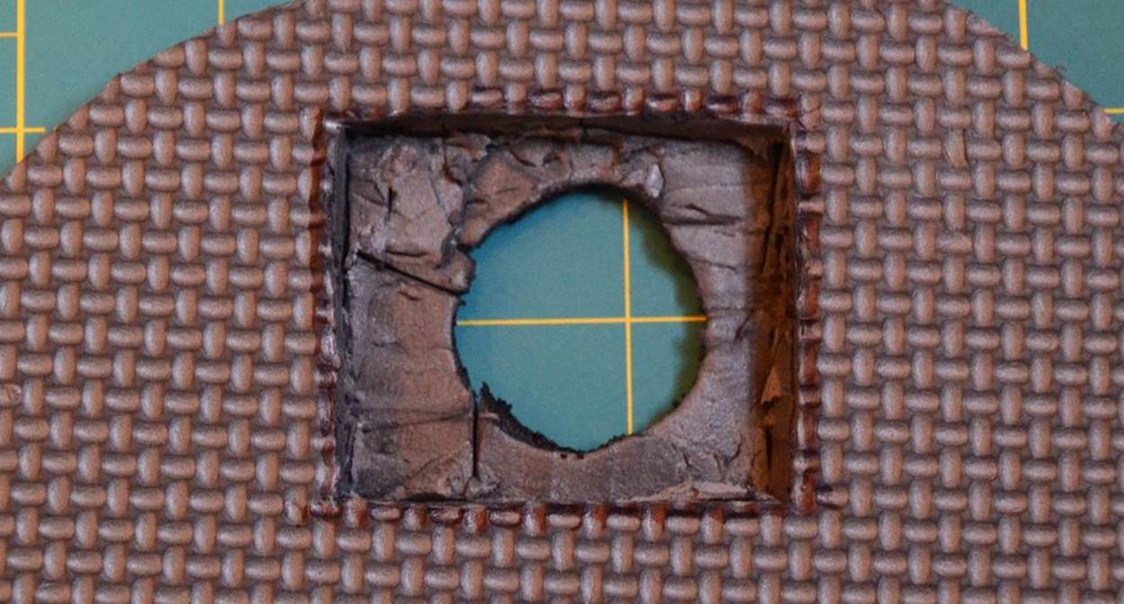
Figure 3-11. Hole to set screen into foam, viewed from back side
You might need to cut a notch on one side for the ribbon connector. Remember, that’s a fragile connector, and if you tear it, about all you can do is wipe your tears and buy a new screen set.
Once the hole is sized properly, you can set the screen into the hole, as shown in Figure 3-12. Turn it over and admire your work!
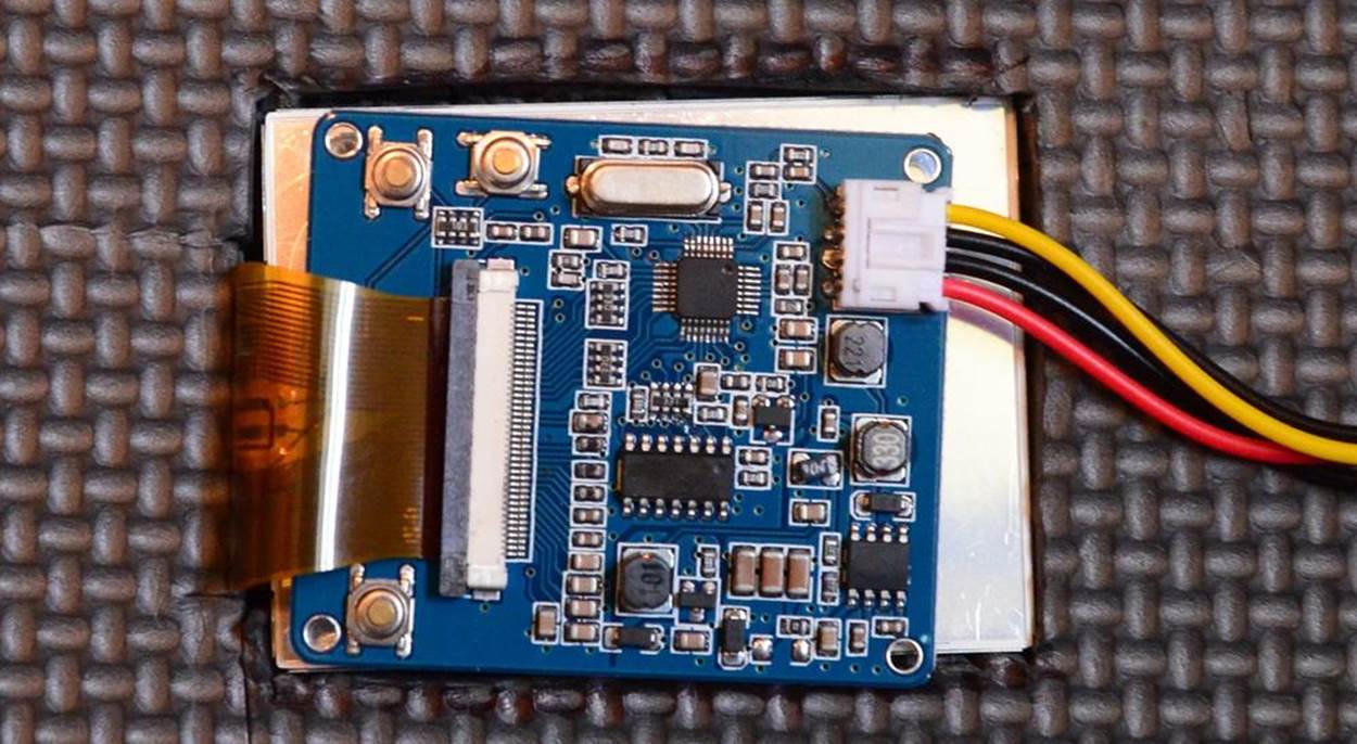
Figure 3-12. Screen set into finished hole, view from back side
Once you get all that taken care of, it’s time to add some realism. You’re going to want the hole to look a bit burnt. Conveniently, you have a burning device in your hands—your hot knife. Use the metal extension between the knife and the handle, which also gets hot, to melt the edges of the hole. They’ll both get smoother and blackened.
You can also paint some scorch marks around the edges and in various other spots for added realism. If you accidentally tapped some other part of your foam with the hot knife while you were working, that’s a great place to create more “battle damage” so it doesn’t look like your shiny, fresh armor got shot through the second you stepped out of the pod/ship/space station.
Put It All Together
Finally, put it all together. Mount the screen in the hole and secure the Raspberry Pi, power supply, and cables in the places you’ve found to hide them. If you’re using the TFT display we use here (see [Hack #57] for further instructions on connecting it), remember also that its ribbon connector is rather fragile and should be secure and protected.
Turn everything on, run your script (or let it autostart), and you’re ready to be a walking war wound, as shown in Figure 3-13. We recommend some nice zombie makeup to complete the look.

Figure 3-13. Screen running in hole window
You can take this hack in other directions as well. Embed a larger screen in the chest of a robot to show its “controls,” or have music videos playing on a dancing robot. Build a Fallout Pip-Boy. Put the camera and screen together in front and create a steampunk “explorer” character whose rig displays a first-person account of what he finds. Dream up all sorts of other possibilities and get to costuming!
Hack 36. Look for Aliens
Your Raspberry Pi can be a part of the world’s largest distributed computing project. You might not actually find signs of alien life, but then, wouldn’t it be fun if you did? And your Pi does all the work.
For more than a decade, the Search for Extraterrestrial Intelligence (SETI) project has used distributed computing through SETI@Home to help with the massive task of sifting through the data from radio telescopes for signs of intelligence beyond Earth. These telescopes receive more noise than anything else, and every bit more data that can be processed means a wider range of frequencies that can be examined. This was originally done using supercomputers until David Gedye organized the SETI@Home project to enable anyone, anywhere to help process all of the data they were acquiring. You can conduct your own piece of the ET hunt with your Raspberry Pi (or several of them!).
You may remember the SETI@Home Classic project as a screensaver that launched in May 1999, which was used by millions. This version, known as SETI@Home Classic, was retired in December 2005 when funding ran out. In those six years, 5,436,301 users from 226 countries provided the equivalent of 2,433,979.781 years of CPU time. While the project didn’t find signs of extraterrestrial life, it did make its mark as the largest computation in history. From then on through today, the project continued through the Berkeley Open Infrastructure for Network Computing (BOINC) open source platform for volunteer grid computing.
BOINC was originally created for SETI@Home in the Space Sciences Laboratory at the University of California, Berkeley and now receives funding from the National Science Foundation. In addition to SETI@Home, it now runs more than 40 other projects, from Enigma@home, which is attempting to decode the remaining three unbroken Enigma messages from World War II, to QMC@Home, which calculates molecular geometry for the field of quantum chemistry.
If you’ve followed the work at CERN’s Large Hadron Collider (LHC), you can use your BOINC installation to participate in the LHC@home project. Once you’ve installed it, you can also connect to those other projects that process data for research in nearly every area of math and science. Data processed by more than 8 million hosts using BOINC, the world’s largest distributed computing project, has led to breakthroughs in AIDS research, found new celestial objects, and even helped find a stolen laptop. The most popular projects running on BOINC as of this writing are:
SETI@Home
The subject of this section
Einstein@Home
Searches for gravitational signals from pulsars and has discovered nearly 50 new pulsars
World Community Grid
An IBM-sponsored humanitarian project that has partnered with hundreds of other organizations on research from cancer to clean energy
BOINC can run continuously, taking advantage of unused processor time as it’s available. Some people wholly devote older equipment to personal “SETI farms.” Devoting a Raspberry Pi to always looking for ET could be your way of contributing to the project. You could even build a “Raspberry Pi farm,” though it would unfortunately not grow pie. But maybe that credit-card-sized computer will be the one that finds definitive signs of life beyond Earth.
Read more about the early history of SETI@Home at http://setiathome.berkeley.edu/classic.php
Begin by installing the BOINC manager and client:
$ su -c 'yum install boinc-manager boinc-client'
or:
$ sudo apt-get install boinc-client boinc-manager
To ensure that the BOINC client starts every time you boot the system, enter:
$ sudo systemctl enable boinc-client.service
Then reboot. If you would prefer to start the BOINC client manually, you can do so any time with the following command:
$ systemctl start boinc-client.service
If your alien-hunting Pi will be devoted to the cause and not needing a monitor, you have the option of installing only the client and starting it at boot. In this case, enter only:
$ su -c yum install boinc-client
or:
$ sudo apt-get install boinc-client
Setting Up BOINC
The following instructions assume that you are using the BOINC Manager, which you can find under System in the Applications Menu if you’re using Fedora or start from the command line by typing boincmgr. It might take a moment before anything appears in the BOINC Manager window the first time. When it does start, you’ll see the error “Unable to connect to the core client.”
Open a terminal and first check that the BOINC Client is running:
$ sudo systemctl status boinc-client.service
You should see something similar to the following:
boinc-client.service - Berkeley Open Infrastructure Network Computing Client
Loaded: loaded (/usr/lib/systemd/system/boinc-client.service; enabled)
Active: active (running) since Wed, 2013-04-17 14:37:22 EST; 1min ago
Process: 19413 ExecStartPre=/usr/bin/chown boinc:boinc /var/log/boinc.log /var/log/boincerr.log (code=exited, status=0/SUCCESS)
Process: 19410 ExecStartPre=/usr/bin/touch /var/log/boinc.log /var/log/boincerr.log (code=exited, status=0/SUCCESS)
Process: 19406 ExecStartPre=/bin/sleep 1 (code=exited, status=0/SUCCESS)
Main PID: 19416 (boinc)
CGroup: name=systemd:/system/boinc-client.service
├ 19416 /bin/bash /usr/bin/boinc --dir /var/lib/boinc
├ 19417 /usr/bin/boinc_client --allow_multiple_clients --dir /var/lib/boinc
├ 19422 ../../projects/setiathome.berkeley.edu/setiathome_6.03_i686-pc-linux-gnu
├ 19423 ../../projects/setiathome.berkeley.edu/setiathome-5.28.x86_64-pc-linux-gnu
├ 19424 ../../projects/setiathome.berkeley.edu/setiathome-5.28.x86_64-pc-linux-gnu
└ 19425 ../../projects/setiathome.berkeley.edu/setiathome-5.28.x86_64-pc-linux-gnu
Apr 17 14:37:21 localhost.localdomain systemd[1]: Starting Berkeley Open Infrastructure Network Computing Client...
Apr 17 14:37:22 localhost.localdomain systemd[1]: Started Berkeley Open Infrastructure Network Computing Client.
You can also see if the client is running by looking for it in the list of currently running processes:
$ ps aux | grep boinc
You should see several boinc processes, including boinc_client in a list similar to the following:
root 16818 0.0 0.0 196284 2656 pts/0 S Apr17 0:00 su boinc
boinc 16819 0.0 0.0 114084 1760 pts/0 S+ Apr17 0:00 bash
jnettles 18734 0.0 0.0 111848 1264 ? S 10:27 0:00 /bin/bash /usr/bin/boincmgr
jnettles 18741 0.1 0.7 706868 28800 ? Sl 10:27 0:16 boinc_gui
boinc 20117 0.0 0.0 113948 1328 ? SNs 14:41 0:00 /bin/bash /usr/bin/boinc --dir /var/lib/boinc
boinc 20118 0.1 0.1 306116 5716 ? SN 14:41 0:00 /usr/bin/boinc_client --allow_multiple_clients --dir /var/lib/boinc
boinc 20123 93.4 0.9 36920 35768 ? RNl 14:41 0:58 ../../projects/setiathome.berkeley.edu/setiathome_6.03_i686-pc-linux-gnu
boinc 20124 90.5 1.1 58124 45052 ? SNl 14:41 0:57 ../../projects/setiathome.berkeley.edu/setiathome-5.28.x86_64-pc-linux-gnu
boinc 20125 91.7 1.1 57616 44536 ? SNl 14:41 0:57 ../../projects/setiathome.berkeley.edu/setiathome-5.28.x86_64-pc-linux-gnu
boinc 20126 92.0 1.1 56964 43892 ? SNl 14:41 0:58 ../../projects/setiathome.berkeley.edu/setiathome-5.28.x86_64-pc-linux-gnu
root 20144 0.0 0.0 109180 880 pts/1 S+ 14:42 0:00 grep --color=auto boinc
If you do not, try starting the service by entering +systemctl start boinc-client.service+.
Once you’ve confirmed that the client is running, it’s time to configure the BOINC Manager:
$ sudo vi /var/lib/boinc/gui_rpc_auth.cfg
This file contains a long string of characters that is your BOINC password. Copy it (Shift+Ctrl+V), then exit (:q!).
Flush the IP tables:
$ sudo iptables -F
Now go to the BOINC Manager window. Go to View → Advanced View (or use Shift+Ctrl+A to switch). Under Advanced → Select Computer, enter 127.0.0.1 for the hostname (using localhost may or may not work) and paste the password you copied fromgui_rpc_auth.cfg.
For security reasons, BOINC Manager requires this password each time you start it. At this point, unless you intend to walk away from it and never use the manager again, you should change some permissions to save yourself from having to copy and paste the password each time.
As you saw when you listed the BOINC processes, installing it created a boinc user as well. That user is currently the owner of everything under /var/lib/boinc/. By adding yourself to the boinc group, you can create permissions that let your BOINC Manager connect to the client without looking up that password each time:
$ su
[Enter password]
$ /usr/sbin/usermod -G boinc -a YOURNAME
$ chmod g+rw /var/lib/boinc
$ chmod g+rw /var/lib/boinc/*.*
$ ln -s /var/lib/boinc/gui_rpc_auth.cfg /home/YOURNAME/gui_rpc_auth.cfg
After you have logged out and back in, you will be added to the boinc group and should no longer have to repeat the password steps when using the BOINC Manager.
BOINC Account Managers
There are several BOINC account managers (which in a sense means BOINC Manager is really just middle management). They manage your BOINC accounts if you’re participating in multiple projects or have BOINC running on multiple systems.
Even if you’re running it only on this one Raspberry Pi, using an account manager will make things easier, and BOINC Manager will prompt you to set one up. The website for BAM!, one of the account managers, explains some of the differences between using an account manager and not using one.
BOINC Account Manager (BAM!)
Despite its name, BOINC Account Manager (BAM!) is not run by the same team as BOINC. It was created by the group that runs BOINCstats, which, as the name implies, provides statistics related to the various projects running on BOINC.
As you’re setting up the BOINC Manager for the first time, you’ll be asked to select an account manager. If you choose BAM!, you will be directed to set up a BAM account at http://bam.boincstats.com, where can create and access your accounts for SETI@Home and other projects.
You can use the same account on multiple Raspberry Pis (or other computers), but make sure that you consistently use the same email address when joining projects and teams. If, after creating an account, you don’t get the BAM! verification email, check your spam folder, or add boincstats.com to the accepted domains filter.
1. Sign in.
2. Select Tools → Add projects. You’ll notice the long list of other distributed computing projects from a wide variety of math and science purposes that you can contribute to using BOINC. You can choose multiple projects—that’s what the BOINC Manager is for.
3. Select SETI@Home. You’ll be asked to either create a login or to give ones you already use. If you create an account, you’ll then be directed to the SETI@Home website, where you’ll finish the registration process.
4. Optionally, find a team to join or create one. If you search for “raspberry pi” in the keywords section, you’ll find the Raspberry Pi Team, created specifically for people using the Pi to run BOINC. Those who simply like the Raspberry Pi but are running BOINC from another system are welcome, too, so don’t take the team’s statistics as being purely from Pis. You can view this team’s statistics at http://boincstats.com/en/stats/-1/team/detail/51ef74e7931bf4eaaf10fe521d6b9df0.
GridRepublic
GridRepublic is an account manager built on the BOINC manager code. It is created by the GridRepublic nonprofit organization that was formed shortly after BOINC to establish the manager concept—a place from which to the control the projects.
To use the GridRepublic manager, you must create an account with them, using the same name as your World Community Grid account if you have one. You then “attach” it to your BOINC installation. You can learn more on the Grid Republic site.
AndroBOINC
If you use an Android smartphone, you can remotely control your BOINC client(s) from your phone. Search in Google Play for “boinc.” There are several unofficial apps, but we recommend AndroBOINC (Figure 3-14). If you don’t have an unlimited data plan, be careful how you set the autorefresh rate when not on WiFi, lest you be sad when next month’s bill comes.
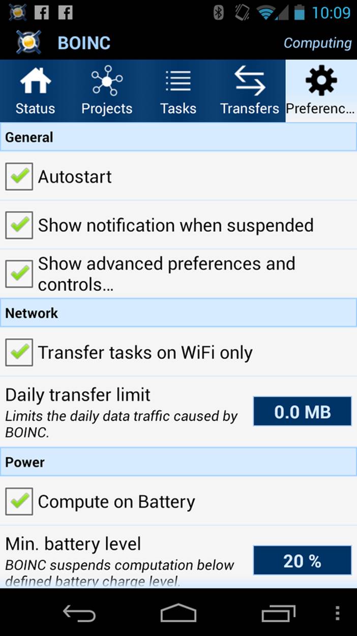
Figure 3-14. AndroBOINC client
There is also an official BOINC Android app available for alpha testing. Read the instructions there carefully if you’re interested in joining the testing.
AndroBOINC offers basic control and status of your BOINC client. Think of it as the BOINC Manager, but on your phone. (You don’t want to run the client on your phone unless you really hate having battery left to do anything else.)
All materials on the site are licensed Creative Commons Attribution-Sharealike 3.0 Unported CC BY-SA 3.0 & GNU Free Documentation License (GFDL)
If you are the copyright holder of any material contained on our site and intend to remove it, please contact our site administrator for approval.
© 2016-2026 All site design rights belong to S.Y.A.