WebGL Textures & Vertices: Beginner's Guide (2015)
This Book's Project List
Lighthouse Texture Map and Tiled Butterfly Fish

Lighthouse Texture Map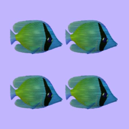
Tiled Butterfly Fish
Cropped Butterfly Fish and Repeating Lighthouse
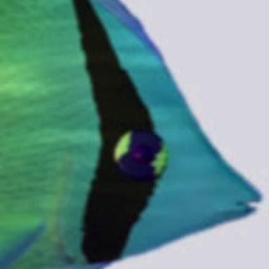
Cropped Butterfly Fish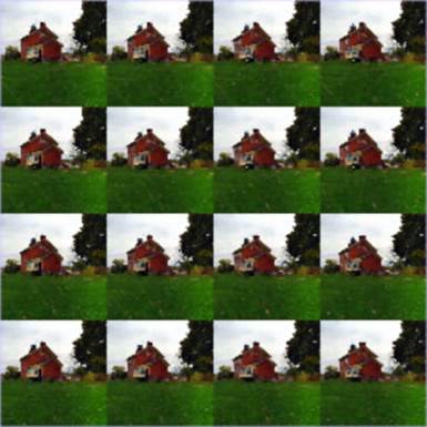
Repeating Lighthouse
Animated Rotationand Bonus Procedural Textures
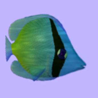
Animated Rotation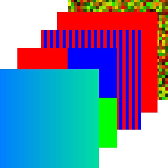
Bonus Procedural Textures!
The project list includes a square mesh texture mapped with a photograph of a lighthouse. Learn to display a cropped portion of an image, with WebGL. Render a mesh texture mapped with the tiled graphic of a Butterfly fish. We'll demonstrate how to map a repeating photograph of the lighthouse with the WebGL method texParameteri(). We explain how to display animation and rotation with the animated Butterfly fish.
Bonus Project: Procedural Textures
WebGL Textures & Vertices: Beginner's Guide includes the full source code and tutorial for generating and using procedural textures. Procedural textures are computer generated graphics. Procedural textures offer a lightweight alternative to JPG, GIF, or PNG image files. Image files must download, however JavaScript alone creates color data for use as a texture. Procedural graphics don't need to download. We'll demonstrate how to declare image colors, then apply the image to a WebGL mesh with JavaScript.
WebGL Overview
WebGL accesses the Graphics Processing Unit (GPU) to provide rapid hardware rendering. GPUs are composed of electronic circuitry designed specifically to display graphics quickly. In other words GPUs display animation, 2D, and 3D graphics to a computer or mobile device's screen, many times faster than software.
3D media demands a high level of processing resources. In the past Web browsers lacked the framework to access the GPU. However, WebGL now provides that framework. WebGL opens new opportunities for 3D media online.
OpenGL ES 2.0
Most native game apps and high performance software communicate to the GPU through languages such as OpenGL, OpenGL ES, or DirectX. With WebGL 1.0, JavaScript communicates to the GPU through a dialect of OpenGL ES 2.0. However, some browsers translate OpenGL ES calls to DirectX. Either way, regardless of the mobile device or desktop computer, WebGL enabled browsers can render high speed graphics with access to the GPU.
This short book demonstrates how to harness the power of the GPU with JavaScript WebGL methods, WebGL properties, and OpenGL ES 2.0 shaders.
Shader Overview
OpenGL ES 2.0 uses shaders to rapidly process vertices and pixel fragments for display to the screen. Each WebGL application requires one vertex and one fragment shader.
WebGL shaders are written with the OpenGL ES Shader Language (GLSL). GLSL is based on C programming syntax. You don't need to understand C programming for this book. We'll explain the shaders line by line.
Conventions
Section titles which start with WebGL API, refer to WebGL specific functions and properties. To find WebGL features, look in the table of contents for entries starting with WebGL API. The WebGL API specific features may look a little peculiar. They resemble OpenGL ES features. However WebGL API functions and properties represent the key to interaction with the GPU for high speed graphics.
Text and diagrams represent vertex coordinates within parenthesis (x, y, z). Texel texture coordinates are represented within square brackets [s, t]. Indices are also represented within square brackets [index].
Object Oriented Design
The book uses prototyped object oriented design with JavaScript classes, rather than functional programming. The source files GLEntity.js and GLControl.js encapsulate methods and properties to initialize and display the book's examples. The sections titled Initialization, Controller Details, and Entity Details cover most of the functionality within GLEntity.js and GLControl.js.
The JavaScript for each unique project's contained in a separate file. For example to texture a square plane use GLSquare.js. To tile a graphic use GLSquareTile.js. To generate procedural textures use GLTexProcedure.js. See the Source Code section in the table of contents for full JavaScript listings of each file.
GLEntity Class
The JavaScript file GLEntity.js defines the GLEntity class. GLEntity encapsulates methods and properties to prepare WebGL textures and meshes, for the example projects. See the Entity Details section, and the full GLEntity source code.
GLControl Class
The JavaScript file GLControl.js defines the GLControl class. GLControl initializes WebGL buffers and shaders for the book's examples. See the Controller Details section and the full GLControl source code.
Efficiency
The source code includes a few features for optimization and efficiency. For example projects store vertex and texture coordinate data in one buffer. One element array buffer accesses both vertex and texture coordinates indirectly. In other words the source code combines or packs data to use fewer resources. If these terms seem unfamiliar, then read on for details.
The next few books in the series Online 3D Media with WebGL, take advantage of the framework setup here. The books use texture atlases to upload a series of images as one texture. We demonstrate how to display multiple meshes with one buffer.
The Book's Structure
First we provide an overview of vertices, meshes, and textures. Next we cover the Lighthouse Texture Map, Crop a Texture Map, Tile a Texture Map, Display Repeating Graphic, and Procedural Textures projects. Then we focus on initialization with the supporting controller file GLControl.js and entity file GLEntity.js. Last we cover the Animated Rotation project which works closely with the controller.
Vertices and Meshes Overview
A vertex represents a point in 3D or 2D space. A mesh represents a set of ordered vertices. The simplest mesh is a triangle composed of three vertices. Combine triangles to display meshes representing almost any form imaginable. For example prepare a few triangles, to display geometric volumes such as cubes and pyramids. Display complex meshes representing people, architecture, and landscapes. This book explains how to order vertices to display a mesh representing a square.
For readers who've studied algebra the following Cartesian coordinate graph should look familiar. The illustration demonstrates a Cartesian coordinate graph with axes labeled X and Y. The book's examples use values for numbers within the range -1 to +1. The center of the 2 dimensional graph is at point (0,0). The upper left corner is at point (-1,+1). The lower right corner is at point (+1,-1).
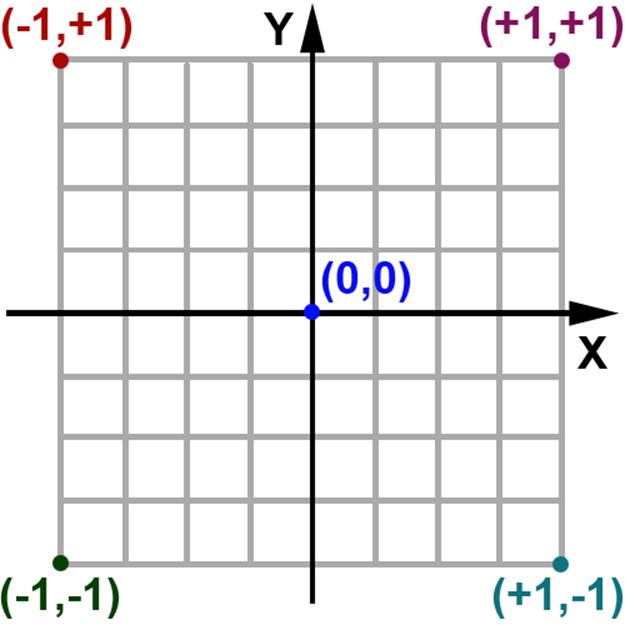
Diagram 1: 2D Cartesian Coordinate Graph
Third Dimension
The book's examples include values for the third coordinate named Z. For example (0,0,0) represents one vertex at the center or origin, of the graph. Point (1,-1,-1) represents one vertex in the lower right back corner of a 2 x 2 unit cube. The following graphic demonstrates the third dimension with a cube. The axis labeled Z provides depth to a scene.
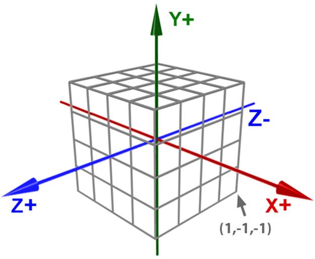
Diagram 2: Cube on with Three Axes
WebGL includes a conceptual viewport. You might think of the viewport as the monitor or a device's display screen. As the value of the Z coordinate decreases, a point recedes off into the distance. As the value of a the Z coordinate increases, a point moves toward the view screen.
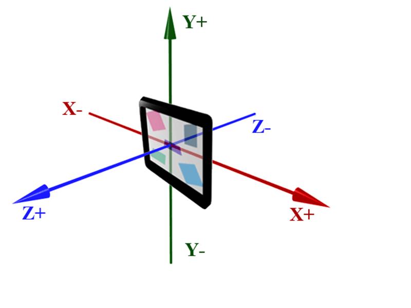
Diagram 3: Viewport
WebGL Texture Overview
The following sections demonstrate how to apply JPG image files as textures on a mesh. However the same process applies to GIF and PNG image files.
This book covers WebGL 1.0, which allows a maximum of 8 textures per example. WebGL 2.0 allows up to 32 textures per example. WebGL enabled browsers include WebGL 1.0 capabilities. However not all WebGL enabled browsers have updated to WebGL 2.0, at this time.
Powers of Two
Image files for most WebGL projects must have pixel dimensions in powers of two. In other words both the width and height must equal a number generated from 2n. For example some acceptable dimensions equal 64, 256, and 512, because 64 = 26, 256 = 28 and 512 = 29.
The width and the height aren't required to match. For example a JPG file with width of 512 pixels and height of 256 pixels works fine with WebGL. Yet a JPG file with width of 300 pixels and height of 200 pixels, causes WebGL to throw an exception, for most texture processing operations. However, some WebGL image processing features allow non power of two images (NPOT).
Cross Domain Rules
The book's examples load image files to display as textures. However some browsers employ cross domain (CORS) rules. That means you must load image files from the same Web domain as the WebGL application. In other words if an image file resides on domain www.test1.com, and the Web page which loads the image resides on domain www.test2.com, the image file won't load.
Additionally some browsers such as Google Chrome and Opera for Windows, disable loading an image file from a Web page on the same computer. In other words if the Web page and image file reside on your computer, the file won't load. However the Firefox browser and Internet Explorer on Windows 8.1, load image files from the local computer. Therefore we to tested on the local PC. Later we uploaded the files to our websiteSevenThunderSoftware.com to test with iPhone 6, Android phones, Windows phone, Google Chrome and Opera browsers.
A work around exists to load image files and test Web pages with various browsers. For example some browsers allow command line options for testing.
Texels
WebGL textures apply with mapping coordinates called texels. Texels include two coordinates labeled S and T. The S coordinate represents the horizontal position within a texture. The T coordinate represents the vertical position within a texture. The book's examples use normalized texels which range from 0 to 1. Each value represents a floating point number. In other words, you may include values after a decimal point for texels.
Consider texels as percentages of a texture divided by 100. For example the texel at [0.5,0.5] represents the exact middle of an image 50% along the X axis and 50% along the Y axis.
The following graphic demonstrates texels mapping a graphic full size across a square plane. Vertex coordinates range from -1.0 to +1.0. However texel coordinates range from 0.0 to +1.0. The book's examples surround texel coordinates with square brackets [] and vertex coordinates with parenthesis (). The book's next project demonstrates how to correlate vertices with texels. In other words we demonstrate how to assign one texel for each vertex.
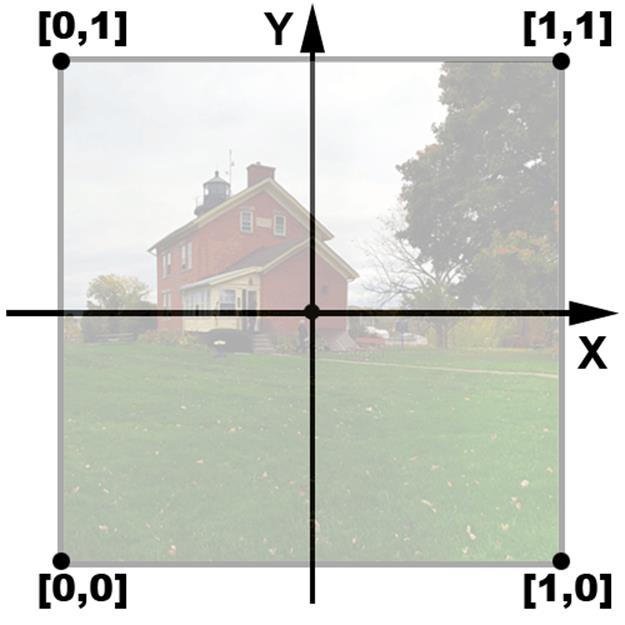
Diagram 4: Texels
The first project titled Lighthouse Texture Map: Display a Photograph on a Square Plane explains how to display a photograph with WebGL vertices and texels.
Lighthouse Texture Map
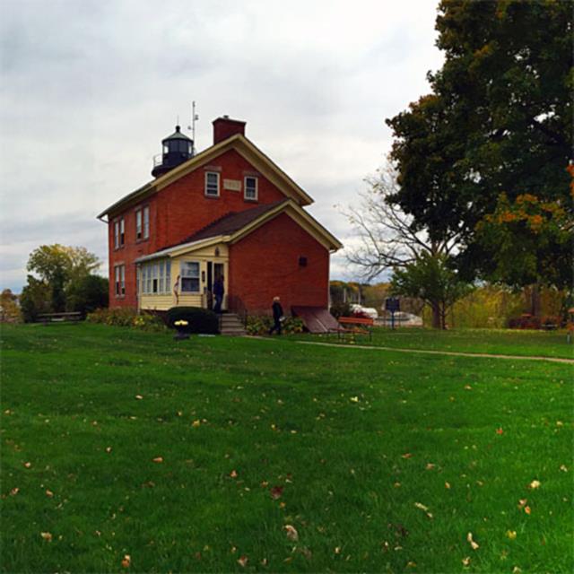
Display a Photograph on a Square Mesh
This project explains how to initialize a square plane mapped with a photograph of a lighthouse. We show how to prepare vertices, texels, and indices for use as drawing buffers. You'll learn to create WebGL arrays of type Float32Array and Uint16Array. This project demonstrates how to get started with WebGL texture mapping.
Start with the Web Page
To display an image full size across a square plane, include Javascript files GLControl.js, GLEntity.js, and GLSquare.js. Place the files between script tags in the header section of a Web page. Add a body onload event listener. The listener creates a new instance of the GLSquare class, as follows.
new GLSquare('assets/lighthouse.jpg')
Each example Web page includes a 512 x 512 square HTML5 canvas element with id of cv. Add two buttons, with id of animStart and animStop.
Sample Web Page
The following listing includes a simplified Web page to display the Lighthouse Texture Map project. To display the book's other sample projects, substitute the last script in the list named GLSquare.js, for the book's other JavaScript files such as GLSquareCrop.js, GLSquareRepeat.js, GLSquareTile.js and GLTexProcedure.js. Substitute the body's onload event listener with new GLSquareCrop(file name), new GLSquareRepeat(file name), new GLSquareTile(file name), or new GLTexProcedure().
<!doctype HTML>
<html>
<head>
<meta http-equiv="content-type" content="text/html; charset=utf-8" />
<title>WebGL Texture</title>
<meta
name="description"
content="WebGL Texture."
/>
<script type="text/javascript"
src="../GLEntity.js"
>
</script>
<script type="text/javascript"
src="../GLControl.js"
>
</script>
<script type="text/javascript"
src="GLSquare.js"
>
</script>
</head>
<body onload="new GLSquare
(
'assets/lighthouse.jpg'
)"
>
<div>
<div id="eDebug">
</div>
<button id="animStop">
Stop
</button>
<button id="animStart">
Rotate
</button>
<canvas id="cv"
width="512"
height="512"
>
Your browser doesn't support canvas.
</canvas>
</div>
</body>
</html>
Listing 1: Sample Web Page
GLSquare.js prepares two arrays with vertices, texels, and indices. The following graphic illustrates texel S,T coordinates associated with vertex X, Y, and Z coordinates. The values in square brackets represent texels. The values in parenthesis represent vertices. For each vertex assign the correct texel. For example texel [0.0,1.0] maps to vertex (-1.0,+1.0,0.0). Texel [1.0,0.0] maps to vertex (+1.0,-1.0,0.0).
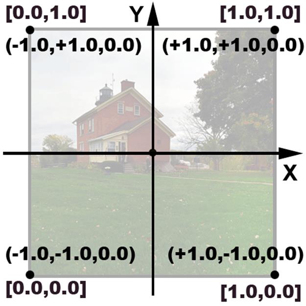
Diagram 5: Associate Vertices with Texels
The following listing from GLSquare.js, generates an array containing interleaved vertices and texels. Interleaved entries alternate between three vertex coordinates and two texel coordinates.
For example the first three entries represent the X, Y, and Z components for one vertex at the top left corner of the square. The next two entries represent the texel's S and T values for the top left corner of the lighthouse image. The next three entries in the array declare the top right corner of the square with X, Y, and Z coordinates. The following two entries declare the top right corner of the lighthouse image with S and T coordinates for one texel.
The array includes the data to declare four vertices mapped with four texels. Represent vertices with X, Y, and Z coordinates. Represent texels with S and T coordinates. The array describes a square plane covered with a graphic at full size. In other words the following array prepares to map an image fully from the top left corner to the bottom right corner of a square mesh.
var aVertices = new Float32Array(
[
// left top:
// X,Y,Z:
-1.0, 1.0, 0.0,
// S,T:
0.0,1.0,
// right top:
// X,Y,Z:
1.0, 1.0, 0.0,
// S,T:
1.0, 1.0,
// right bottom:
// X,Y,Z;
1.0, -1.0, 0.0,
// S,T:
1.0, 0.0,
// left bottom
// X,Y,Z:
-1.0, -1.0, 0.0,
// S,T:
0.0, 0.0,
]
);
Listing 2: Interleaved Array
WebGL API Cast Float32Array(Array)
The WebGL API cast Float32Array(Array) formats the JavaScript array of Number to a typed array of floating point numbers, where each number has 32 bits of precision. The only parameter is a JavaScript array of Number. TheFloat32Array(Array) cast, returns a Float32Array type containing the numerical data from the Array in the parameter list.
The next step explains how to prepare data for an element array buffer.
Element Array Buffer
Element array buffers use indices to order the display of each vertex and texel. Additionally indices allow us to re use useentries in the array.
An element array buffer tells WebGL to access vertex and texel coordinates with integer indices. Indices provide a shorthand method to access multiple values. This section demonstrates how to use the previous interleaved array, with indices. One index represents five values. One index points to three vertex coordinates for X, Y, and Z values, plus two texel coordinates for S and T values.
The following table demonstrates the association between indices, vertices, and texels. Index entries begin at 0 and end at the length of an array minus 1. For example index [0] points to the first vertex. Index [1] points to the second vertex. Index [3] points to the last vertex declared in an array, when the array's length equals 4. Upload an array of vertices and texels to the GPU, then use an element array buffer of indices, to tell WebGL which order to draw the values. The section titled Controller Details explains how to upload arrays as buffers to the GPU. This section concentrates on preparing typed arrays.
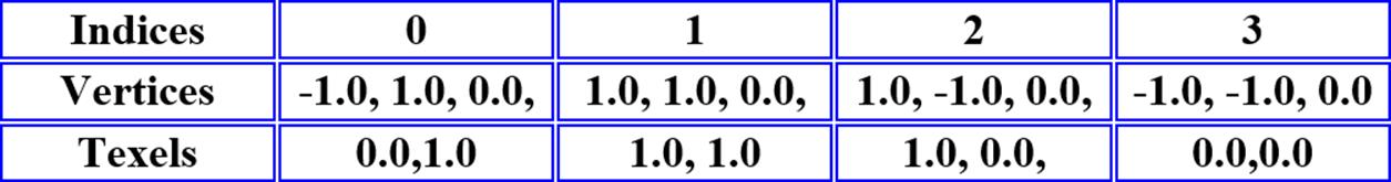
Diagram 6: Associate Indices with Vertices and Texels
Winding Order
The following graphic demonstrates a WebGL square plane on a Cartesian coordinate graph with counter clockwise winding order. Two triangles composed of three vertices each, and four vertices total, display one square plane.
The solid black circles represent the starting vertex of a triangle. Arrows point to the the ending vertex of a triangle. The values in parenthesis represent vertex X, Y, and Z coordinates. The values in brackets represent indices.
Trace the direction of lines for each triangle, from the starting vertex, to the middle vertex, then the terminal ending vertex. The lines spiral in a counter clockwise direction. WebGL's default setting determines the front face of a mesh, based on counter clockwise vertex ordering.
Culling
The book's examples display both the front and back face of each mesh. For example both the back and the front of the square mapped with a lighthouse, display during animated rotation. However, efficient applications often enableculling. Culling instructs WebGL to process only those elements which face the viewport. In other words triangles which face away from the display screen, seem to disappear. The triangles disappear because the GPU doesn't waste processing resources to render them. WebGL determines which elements face the viewport based on winding order.
With the default counter clockwise winding order, call the WebGL API method gl.enable(gl.CULL_FACE), to hide clockwise ordered triangles. The variable gl references a WebGLContext. The section titled Obtain a WebGLContext explains how to obtain a reference to the WebGLContext. The property gl.CULL_FACE is a WebGL constant.
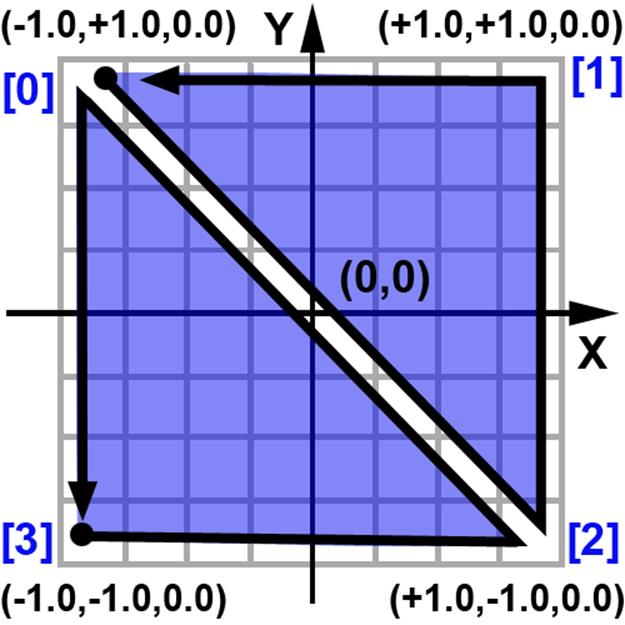
Diagram 7: Winding Order
Create an Element Array
The preceding graphic illustrates the first triangle starting at index number 3 which points to vertex (-1.0,-1.0,0.0). The line proceeds from index 3 to index 2. The triangle then ends at vertex 0. You could declare just the first triangle with the following element index array. When rendered, only the bottom left triangle would display.
var aIndices = new Uint16Array([
3,2,0
]);
Listing 3: Element Array for One Triangle
However we also want to display the second triangle. Therefore create an element array with six entries, allowing three entries for each triangle. The following listing declares an element array for the square plane. Notice this example uses the vertices and texels declared for indices 0 and 2 twice.
var aIndices = new Uint16Array([
// triangle 1
3,2,0,
// triangle 2
0,2,1,
]);
Listing 4: Element Array for One Square
WebGL API Cast Uint16Array(Array)
WebGL requires typed arrays. The type Uint16Array represents an array of 16 bit unsigned integers. Acceptable Uint16Array entries include non negative whole numbers which don't exceed sixteen bits of information. That means values range between 0 and 216 - 1. The greatest value equals 65,535. Each array entry represents a whole number, without a decimal point. After initialization, the developer can't change the size of a Uint16Array.
JavaScript to Display a Textured Square
The following listing demonstrates the formal declaration for GLSquare(String). The only parameter to the GLSquare(String) constructor is a String representing an image file name and path. After initialization, the image displays on the mesh as a WebGLTexture.
var GLSquare = function(s)
{
//Implementation...
}
Listing 5: GLSquare Formal Declaration
Use GLSquare(String) to Texture a Square
Create a new GLSquare(String) reference when the HTML Web page's body onload event handler triggers. The following listing demonstrates creating a new GLSquare(String) for the Lighthouse Texture Map example. The file path assets/lighthouse.jpg tells GLSquare to display the lighthouse graphic.
<body onload="new GLSquare
(
'assets/lighthouse.jpg'
)"
>
Listing 6: New GLSquare for Lighthouse
Use GLEntity(String,Number) to Declare Texture Values
The GLSquare constructor initializes a reference to GLEntity. File GLEntity.js defines the GLEntity class. The book's examples re use GLEntity to prepare WebGL textures and matrices. One GLEntity represents a unique element for display with WebGL. GLEntity encapsulates the image object, texture, texture related methods, and a transformation matrix. Later we demonstrate how to modify transformation matrices to move and rotate WebGL mesh elements.
The Lighthouse Texture Map project creates one GLEntity. The first parameter to GLEntity is the String passed as a parameter to the GLSquare constructor. In this case we want to display assets/lighthouse.jpg. You can display JPG, GIF, or PNG files. Pass the formal parameter to the GLSquare constructor, named s. The second parameter is the entity's index. Pass 0 for the index parameter.
Each example project uses an array of GLEntity. The following listing demonstrates creating an array with one GLEntity, for the Lighthouse Texture Map example.
var aIm = new Array();
var n = new GLEntity
(
s,
0
);
aIm.push(n);
Listing 7: GLEntity for Lighthouse Texture Map
Create a Controller: GLControl(Float32Array, Uint16Array, Array<GLEntity>, glDemo)
All of the book's examples initialize a GLControl controller. The first parameter to the GLControl constructor is a Float32Array containing vertex and texel coordinates. The second parameter is a Uint16Array containing element array entries. The third parameter is an array of GLEntity. The fourth parameter is a reference to the current project. Use the this keyword to pass a reference to the GLSquare class.
For example pass array variables initialized with the GLSquare constructor, to the GLControl constructor. Include the Float32Array named aVertices, the Uint16Array named aIndices, and the non typed Array named aIm of GLEntity. Pass this of type GLSquare as the last parameter. The following listing demonstrates initializing the controller within the GLSquare constructor.
var controller = new GLControl
(
aVertices,
aIndices,
aIm,
this
);
Listing 8: Initialize the Controller
We have now covered all the source code specific to GLSquare. You can pass GIF, PNG, or JPG image files to the GLSquare constructor. See the fully commented GLSquare source code.
Lighthouse Texture Map Summary
This project explained how to initialize a square plane mapped with a photograph of a lighthouse. We demonstrated how to prepare vertices, texels, and element arrays. We covered typed arrays for use with WebGL including Float32Array and Uint16Array. Next we'll modify texels to crop a texture.
All materials on the site are licensed Creative Commons Attribution-Sharealike 3.0 Unported CC BY-SA 3.0 & GNU Free Documentation License (GFDL)
If you are the copyright holder of any material contained on our site and intend to remove it, please contact our site administrator for approval.
© 2016-2026 All site design rights belong to S.Y.A.