Linux Kernel Networking: Implementation and Theory (2014)
CHAPTER 14. Advanced Topics
Chapter 13 dealt with the InfiniBand subsystem and its implementation in Linux. This chapter deals with several advanced topics and some topics that didn’t fit logically into other chapters. The chapter starts with a discussion about network namespaces, a type of lightweight process virtualization mechanism that was added to Linux in recent years. I will discuss the namespaces implementation in general and network namespaces in particular. You will learn that only two new system calls are needed in order to implement namespaces. You will also see several examples of how simple it is to create and manage network namespaces with the ip command of iproute2, and how simple it is to move one network device from one network namespace to another and to attach a specified process to a specified network namespace. The cgroups subsystem also provides resource management solution, which is different from namespaces. I will describe the cgroups subsystem and its two network modules, net_prio and cls_cgroup, and give two examples of using these cgroup network modules.
Later on in this chapter, you will learn about Busy Poll Sockets and how to tune them. The Busy Poll Sockets feature provides an interesting performance optimization technique for sockets that need low latency and are willing to pay a cost of higher CPU utilization. The Busy Poll Sockets feature is available from kernel 3.11. I will also cover the Bluetooth subsystem, the IEEE 802.15.4 subsystem and the Near Field Communication (NFC) subsystem; these three subsystems typically work in short range networks, and the development of new features for these subsystem is progressing at a rapid pace. I will also discuss Notification Chains, which is an important mechanism that you may encounter while developing or debugging kernel networking code and the PCI subsystem, as many network devices are PCI devices. I will not delve deep into the PCI subsystem details, as this book is not about device drivers. I will conclude the chapter with three short sections, one about the teaming network driver (which is the new kernel link aggregation solution), one about the Point-to-Point over Ethernet (PPPoE) Protocol, and finally one about Android.
Network Namespaces
This section covers Linux namespaces, what they are for and how they are implemented. It includes an in-depth discussion of network namespaces, giving some examples that will demonstrate their usage. Linux namespaces are essentially a virtualization solution. Operating system virtualization was implemented in mainframes many years before solutions like Xen or KVM hit the market. Also with Linux namespaces, which are a form of process virtualization, the idea is not new at all. It was tried in the Plan 9 operating system (see this article from 1992: “The Use of Name Spaces in Plan 9”, www.cs.bell-labs.com/sys/doc/names.html).
Namespaces is a form of lightweight process virtualization, and it provides resource isolation. As opposed to virtualization solutions like KVM or Xen, with namespaces you do not create additional instances of the operating system on the same host, but use only a single operating system instance. I should mention in this context that the Solaris operating system has a virtualization solution named Solaris Zones, which also uses a single operating system instance, but the scheme of resource partitioning is somewhat different than that of Linux namespaces (for example, in Solaris Zones there is a global zone which is the primary zone, and which has more capabilities). In the FreeBSD operating system there is a mechanism called jails, which also provides resource partitioning without running more than one instance of the kernel.
The main idea of Linux namespaces is to partition resources among groups of processes to enable a process (or several processes) to have a different view of the system than processes in other groups of processes. This feature is used, for example, to provide resource isolation in the Linux containers project (http://lxc.sourceforge.net/). The Linux containers project also uses another resource management mechanism that is provided by the cgroups subsystem, which will be described later in this chapter. With containers, you can run different Linux distributions on the same host using one instance of the operating systems. Namespaces are also needed for the checkpoint/restore feature, which is used in high performance computing (HPC). For example, it is used in CRIU (http://criu.org/Main_Page), a software tool of OpenVZ (http://openvz.org/Main_Page), which implements checkpoint/restore functionality for Linux processes mostly in userspace, though there are very few places when CRIU kernel patches were merged. I should mention that there were some projects to implement checkpoint/restore in the kernel, but these projects were not accepted in mainline because they were too complex. For example, take the CKPT project: https://ckpt.wiki.kernel.org/index.php/Main_Page. The checkpoint/restore feature (sometimes referred to as checkpoint/restart) enables stopping and saving several processes on a filesystem, and at a later time restores those processes (possibly on a different host) from the filesystem and resumes its execution from where it was stopped. Without namespaces, checkpoint/restore has very limited use cases, in particular live migration is only possible with them. Another use case for network namespaces is when you need to set up an environment that needs to simulate different network stacks for testing, debugging, etc. For readers who want to learn more about checkpoint/restart, I suggest reading the article “Virtual Servers and Checkpoint/Restart in Mainstream Linux,” by Sukadev Bhattiprolu, Eric W. Biederman, Serge Hallyn, and Daniel Lezcano.
Mount namespaces were the first type of Linux namespaces to be merged in 2002, for kernel 2.4.19. User namespaces were the last to be implemented, in kernel 3.8, for almost all filesystems types. It could be that additional namespaces will be developed, as is discussed later in this section. For creating a namespace you should have the CAP_SYS_ADMIN capability for all namespaces, except for the user namespace. Trying to create a namespace without the CAP_SYS_ADMIN capability for all namespaces, except for the user namespace, will result with an –EPRM error (“Operation not permitted”). Many developers took part in the development of namespaces, among them are Eric W. Biederman, Pavel Emelyanov, Al Viro, Cyrill Gorcunov, Andrew Vagin, and more.
After getting some background about process virtualization and Linux namespaces, and how they are used, you are now ready to dive in into the gory implementation details.
Namespaces Implementation
As of this writing, six namespaces are implemented in the Linux kernel. Here is a description of the main additions and changes that were needed in order to implement namespaces in the Linux kernel and to support namespaces in userspace packages:
· A structure called nsproxy (namespace proxy) was added. This structure contains pointers to five namespaces out of the six namespaces that are implemented. There is no pointer to the user namespace in the nsproxy structure; however, all the other five namespace objects contain a pointer to the user namespace object that owns them, and in each of these five namespaces, the user namespace pointer is called user_ns. The user namespace is a special case; it is a member of the credentials structure (cred), called user_ns. Thecred structure represents the security context of a process. Each process descriptor (task_struct) contains two cred objects, for effective and objective process descriptor credentials. I will not delve into all the details and nuances of user namespaces implementation, since this is not in the scope of this book. An nsproxy object is created by the create_nsproxy() method and it is released by the free_nsproxy() method. A pointer to nsproxy object, which is also called nsproxy, was added to the process descriptor (a process descriptor is represented by the task_struct structure, include/linux/sched.h.) Let’s take a look at the nsproxy structure, as it’s quite short and should be quite self-explanatory:
struct nsproxy {
atomic_t count;
struct uts_namespace *uts_ns;
struct ipc_namespace *ipc_ns;
struct mnt_namespace *mnt_ns;
struct pid_namespace *pid_ns;
struct net *net_ns;
};
(include/linux/nsproxy.h)
· You can see in the nsproxy structure five pointers of namespaces (there is no user namespace pointer). Using the nsproxy object in the process descriptor (task_struct object) instead of five namespace objects is an optimization. When performing fork(), a new child is likely to live in the same set of namespaces as its parent. So instead of five reference counter increments (one per each namespace), only one reference counter increment would happen (of the nsproxy object). The nsproxy count member is a reference counter, which is initialized to 1 when the nsproxy object is created by the create_nsproxy() method, and which is decremented by the put_nsproxy() method and incremented by the get_nsproxy() method. Note that the pid_ns member of thensproxy object was renamed to pid_ns_for_children in kernel 3.11.
· A new system call, unshare(), was added. This system call gets a single parameter that is a bitmask of CLONE* flags. When the flags argument consists of one or more namespace CLONE_NEW* flags, the unshare() system call performs the following steps:
· First, it creates a new namespace (or several namespaces) according to the specified flag. This is done by calling the unshare_nsproxy_namespaces() method, which in turn creates a new nsproxy object and one or more namespaces by calling thecreate_new_namespaces() method. The type of the new namespace (or namespaces) is determined according to the specified CLONE_NEW* flag. The create_new_namespaces() method returns a new nsproxy object that contains the new created namespace (or namespaces).
· Then it attaches the calling process to that newly created nsproxy object by calling the switch_task_namespaces() method.
When CLONE_NEWPID is the flag of the unshare() system call, it works differently than with the other flags; it's an implicit argument to fork(); only the child task will happen in a new PID namespace, not the one calling the unshare() system call. Other CLONE_NEW* flags immediately put the calling process into a new namespace.
The six CLONE_NEW* flags, which were added to support the creation of namespaces, are described later in this section. The implementation of the unshare() system call is in kernel/fork.c.
· A new system call, setns(), was added. It attaches the calling thread to an existing namespace. Its prototype is int setns(int fd, int nstype); the parameters are:
· fd: A file descriptor which refers to a namespace. These are obtained by opening links from the /proc/<pid>/ns/ directory.
· nstype: An optional parameter. When it is one of the new CLONE_NEW* namespaces flags, the specified file descriptor must refer to a namespace which matches the type of the specified CLONE_NEW* flag. When the nstype is not set (its value is 0) the fdargument can refer to a namespace of any type. If the nstype does not correspond to the namespace type associated with the specified fd, a value of –EINVAL is returned.
You can find the implementation of the setns() system call in kernel/nsproxy.c.
· The following six new clone flags were added in order to support namespaces:
· CLONE_NEWNS (for mount namespaces)
· CLONE_NEWUTS (for UTS namespaces)
· CLONE_NEWIPC (for IPC namespaces)
· CLONE_NEWPID (for PID namespaces)
· CLONE_NEWNET (for network namespaces)
· CLONE_NEWUSER (for user namespaces)
The clone() system call is used traditionally to create a new process. It was adjusted to support these new flags so that it will create a new process attached to a new namespace (or namespaces). Note that you will encounter usage of the CLONE_NEWNET flag, for creating a new network namespace, in some of the examples later in this chapter.
· Each subsystem, from the six for which there is a namespace support, had implemented a unique namespace of its own. For example, the mount namespace is represented by a structure called mnt_namespace, and the network namespace is represented by a structure called net, which is discussed later in this section. I will mention the other namespaces later in this chapter.
· For namespaces creation, a method named create_new_namespaces() was added (kernel/nsproxy.c). This method gets as a first parameter a CLONE_NEW* flag or a bitmap of CLONE_NEW* flags. It first creates an nsproxy object by calling thecreate_nsproxy() method, and then it associates a namespace according to the specified flag; since the flag can be a bitmask of flags, the create_new_namespaces() method can associate more than one namespace. Let’s take a look at thecreate_new_namespaces() method:
static struct nsproxy *create_new_namespaces(unsigned long flags,
struct task_struct *tsk, struct user_namespace *user_ns,
struct fs_struct *new_fs)
{
struct nsproxy *new_nsp;
int err;
Allocate an nsproxy object and initialize its reference counter to 1:
new_nsp = create_nsproxy();
if (!new_nsp)
return ERR_PTR(-ENOMEM);
. . .
After creating successfully an nsproxy object, we should create namespaces according to the specified flags, or associate an existing namespace to the new nsproxy object we created. We start by calling copy_mnt_ns(), for the mount namespaces, and then we callcopy_utsname(), for the UTS namespace. I will describe here shortly the copy_utsname() method, because the UTS namespace is discussed in the “UTS Namespaces Implementation” section later in this chapter. If the CLONE_NEWUTS is not set in the specified flags of thecopy_utsname() method, the copy_utsname() method does not create a new UTS namespace; it returns the UTS namespace that was passed by tsk->nsproxy->uts_ns as the last parameter to the copy_utsname() method. In case the CLONE_NEWUTS is set, thecopy_utsname() method clones the specified UTS namespace by calling the clone_uts_ns() method. The clone_uts_ns() method, in turn, allocates a new UTS namespace object, copies the new_utsname object of the specified UTS namespace (tsk->nsproxy->uts_ns) into the new_utsname object of the newly created UTS namespace object, and returns the newly created UTS namespace. You will learn more about the new_utsname structure in the “UTS Namespaces Implementation” section later in this chapter:
new_nsp->uts_ns = copy_utsname(flags, user_ns, tsk->nsproxy->uts_ns);
if (IS_ERR(new_nsp->uts_ns)) {
err = PTR_ERR(new_nsp->uts_ns);
goto out_uts;
}
. . .
After handling the UTS namespace, we continue with calling the copy_ipcs() method to handle the IPC namespace, copy_pid_ns() to handle the PID namespace, and copy_net_ns() to handle the network namespace. Note that there is no call to the copy_user_ns()method, as the nsproxy does not contain a pointer to user namespace, as was mentioned earlier. I will describe here shortly the copy_net_ns() method. If the CLONE_NEWNET is not set in the specified flags of the create_new_namespaces() method, the copy_net_ns()method returns the network namespace that was passed as the third parameter to the copy_net_ns() method, tsk->nsproxy->net_ns, much like the copy_utsname() did, as you saw earlier in this section. If the CLONE_NEWNET is set, the copy_net_ns() method allocates a new network namespace by calling the net_alloc() method, initializes it by calling the setup_net() method, and adds it to the global list of all network namespaces, net_namespace_list:
new_nsp->net_ns = copy_net_ns(flags, user_ns, tsk->nsproxy->net_ns);
if (IS_ERR(new_nsp->net_ns)) {
err = PTR_ERR(new_nsp->net_ns);
goto out_net;
}
return new_nsp;
}
Note that the setns() system call, which does not create a new namespace but only attaches the calling thread to a specified namespace, also calls create_new_namespaces(), but it passes 0 as a first parameter; this implies that only an nsproxy is created by calling the create_nsproxy() method, but no new namespace is created, but the calling thread is associated with an existing network namespace which is identified by the specified fd argument of the setns() system call. Later in the setns() system call implementation, the switch_task_namespaces() method is invoked, and it assigns the new nsproxy which was just created to the calling thread (see kernel/nsproxy.c).
· A method named exit_task_namespaces()was added in kernel/nsproxy.c. It is called when a process is terminated, by the do_exit() method (kernel/exit.c). The exit_task_namespaces() method gets the process descriptor (task_structobject) as a single parameter. In fact the only thing it does is call the switch_task_namespaces() method, passing the specified process descriptor and a NULL nsproxy object as arguments. The switch_task_namespaces() method, in turn, nullifies thensproxy object of the process descriptor of the process which is being terminated. If there are no other processes that use that nsproxy, it is freed.
· A method named get_net_ns_by_fd() was added. This method gets a file descriptor as its single parameter, and returns the network namespace associated with the inode that corresponds to the specified file descriptor. For readers who are not familiar with filesystems and with inode semantics, I suggest reading the “Inode Objects” section of Chapter 12, “The Virtual Filesystem,” in Understanding the Linux Kernel by Daniel P. Bovet and Marco Cesati (O’Reilly, 2005).
· A method named get_net_ns_by_pid()was added. This method gets a PID number as a single argument, and it returns the network namespace object to which this process is attached.
· Six entries were added under /proc/<pid>/ns, one for each namespace. These files, when opened, should be fed into the setns() system call. You can use ls –al or readlink to display the unique proc inode number which is associated with a namespace. This unique proc inode is created by the proc_alloc_inum() method when the namespace is created, and is freed by the proc_free_inum() method when the namespace is released. See, for example, in the create_pid_namespace() method inkernel/pid_namespace.c. In the following example, the number in square brackets on the right is the unique proc inode number of each namespace:
· ls -al /proc/1/ns/
total 0
dr-x--x--x 2 root root 0 Nov 3 13:32 .
dr-xr-xr-x 8 root root 0 Nov 3 12:17 ..
lrwxrwxrwx 1 root root 0 Nov 3 13:32 ipc -> ipc:[4026531839]
lrwxrwxrwx 1 root root 0 Nov 3 13:32 mnt -> mnt:[4026531840]
lrwxrwxrwx 1 root root 0 Nov 3 13:32 net -> net:[4026531956]
lrwxrwxrwx 1 root root 0 Nov 3 13:32 pid -> pid:[4026531836]
lrwxrwxrwx 1 root root 0 Nov 3 13:32 user -> user:[4026531837]
lrwxrwxrwx 1 root root 0 Nov 3 13:32 uts -> uts:[4026531838]
· A namespace can stay alive if either one of the following conditions is met:
· The namespace file under /proc/<pid>/ns/ descriptor is held.
· bind mounting the namespace proc file somewhere else, for example, for PID namespace, by: mount --bind /proc/self/ns/pid /some/filesystem/path
· For each of the six namespaces, a proc namespace operations object (an instance of proc_ns_operations structure) is defined. This object consists of callbacks, such as inum, to return the unique proc inode number associated with the namespace or install, for namespace installation (in the install callback, namespace specific actions are performed, such as attaching the specific namespace object to the nsproxy object, and more; the install callback is invoked by the setns system call). The proc_ns_operationsstructure in defined in include/linux/proc_fs.h. Following is the list of the six proc_ns_operations objects:
· utsns_operations for UTS namespace (kernel/utsname.c)
· ipcns_operations for IPC namespace (ipc/namespace.c)
· mntns_operations for mount namespaces (fs/namespace.c)
· pidns_operations for PID namespaces (kernel/pid_namespace.c)
· userns_operations for user namespace (kernel/user_namespace.c)
· netns_operations for network namespace (net/core/net_namespace.c)
· For each namespace, except the mount namespace, there is an initial namespace:
· init_uts_ns: For UTS namespace (init/version.c).
· init_ipc_ns: For IPC namespace (ipc/msgutil.c).
· init_pid_ns: For PID namespace (kernel/pid.c).
· init_net: For network namespace (net/core/net_namespace.c).
· init_user_ns: For user namespace (kernel/user.c).
· An initial, default nsproxy object is defined: it is called init_nsproxy and it contains pointers to five initial namespaces; they are all initialized to be the corresponding specific initial namespace except for the mount namespace, which is initialized to be NULL:
· struct nsproxy init_nsproxy = {
.count = ATOMIC_INIT(1),
.uts_ns = &init_uts_ns,
#if defined(CONFIG_POSIX_MQUEUE) || defined(CONFIG_SYSVIPC)
.ipc_ns = &init_ipc_ns,
#endif
.mnt_ns = NULL,
.pid_ns = &init_pid_ns,
#ifdef CONFIG_NET
.net_ns = &init_net,
#endif
};
(kernel/nsproxy.c)
· A method named task_nsproxy() was added; it gets as a single parameter a process descriptor (task_struct object), and it returns the nsproxy associated with the specified task_struct object. See include/linux/nsproxy.h.
These are the six namespaces available in the Linux kernel as of this writing:
· Mount namespaces: The mount namespaces allows a process to see its own view of the filesystem and of its mount points. Mounting a filesystem in one mount namespace does not propagate to the other mount namespaces. Mount namespaces are created by setting the CLONE_NEWNS flag when calling the clone() or unshare() system calls. In order to implement mount namespaces, a structure called mnt_namespace was added (fs/mount.h), and nsproxy holds a pointer to an mnt_namespace object called mnt_ns. Mount namespaces are available from kernel 2.4.19. Mount namespaces are implemented primarily in fs/namespace.c. When creating a new mount namespace, the following rules apply:
· All previous mounts will be visible in the new mount namespace.
· Mounts/unmounts in the new mount namespace are invisible to the rest of the system.
· Mounts/unmounts in the global mount namespace are visible in the new mount namespace.
Mount namespaces use a VFS enhancement called shared subtrees, which was introduced in the Linux 2.6.15 kernel; the shared subtrees feature introduced new flags: MS_PRIVATE, MS_SHARED, MS_SLAVE and MS_UNBINDABLE . (Seehttp://lwn.net/Articles/159077/ and Documentation/filesystems/sharedsubtree.txt.) I will not discuss the internals of mount namespaces implementation. For readers who want to learn more about mount namespaces usage, I suggest reading the following article: “Applying Mount Namespaces,” by Serge E. Hallyn and Ram Pai (http://www.ibm.com/developerworks/linux/library/l-mount-namespaces/index.html).
· PID namespaces: The PID namespaces provides the ability for different processes in different PID namespaces to have the same PID. This feature is a building block for Linux containers. It is important for checkpoint/restore of a process, because a process checkpointed on one host can be restored on a different host even if there is a process with the same PID on that host. When creating the first process in a new PID namespace, its PID is 1. The behavior of this process is somewhat like the behavior of the init process. This means that when a process dies, all its orphaned children will now have the process with PID 1 as their parent (child reaping). Sending SIGKILL signal to a process with PID 1 does not kill the process, regardless of in which namespace the SIGKILL signal was sent, in the initial PID namespace or in any other PID namespace. But killing init of one PID namespace from another (parent one) will work. In this case, all of the tasks living in the former namespace will be killed and the PID namespace will be stopped. PID namespaces are created by setting the CLONE_NEWPID flag when calling the clone() or unshare() system calls. In order to implement PID namespaces, a structure called pid_namespace was added (include/linux/pid_namespace.h), and nsproxy holds a pointer to apid_namespace object called pid_ns. In order to have PID namespaces support, CONFIG_PID_NS should be set. PID namespaces are available from kernel 2.6.24. PID namespaces are implemented primarily in kernel/pid_namespace.c.
· Network namespaces: The network namespace allows creating what appears to be multiple instances of the kernel network stack. Network namespaces are created by setting the CLONE_NEWNET flag when calling the clone() or unshare() system calls. In order to implement network namespaces, a structure called net was added (include/net/net_namespace.h), and nsproxy holds a pointer to a net object called net_ns. In order to have network namespaces support, CONFIG_NET_NS should be set. I will discuss network namespaces later in this section. Network namespaces are available from kernel 2.6.29. Network namespaces are implemented primarily in net/core/net_namespace.c.
· IPC namespaces: The IPC namespace allows a process to have its own System V IPC resources and POSIX message queues resources. IPC namespaces are created by setting the CLONE_NEWIPC flag when calling the clone() or unshare() system calls. In order to implement IPC namespaces, a structure called ipc_namespace was added (include/linux/ipc_namespace.h), and nsproxy holds a pointer to an ipc_namespace object called ipc_ns. In order to have IPC namespaces support, CONFIG_IPC_NS should be set. Support for System V IPC resources is available in IPC namespaces from kernel 2.6.19. Support for POSIX message queues resources in IPC namespaces was added later, in kernel 2.6.30. IPC namespaces are implemented primarily in ipc/namespace.c.
· UTS namespaces: The UTS namespace provides the ability for different UTS namespaces to have different host name or domain name (or other information returned by the uname() system call). UTS namespaces are created by setting the CLONE_NEWUTS flag when calling the clone() or unshare() system calls. UTS namespace implementation is the simplest among the six namespaces that were implemented. In order to implement the UTS namespace, a structure called uts_namespace was added (include/linux/utsname.h), and nsproxy holds a pointer to a uts_namespace object called uts_ns. In order to have UTS namespaces support, CONFIG_UTS_NS should be set. UTS namespaces are available from kernel 2.6.19. UTS namespaces are implemented primarily in kernel/utsname.c.
· User namespaces: The user namespace allows mapping of user and group IDs. This mapping is done by writing to two procfs entries that were added for supporting user namespaces: /proc/sys/kernel/overflowuid and/proc/sys/kernel/overflowgid. A process attached to a user namespace can have a different set of capabilities then the host. User namespaces are created by setting the CLONE_NEWUSER flag when calling the clone() or unshare() system calls. In order to implement user namespaces, a structure called user_namespace was added (include/linux/user_namespace.h). The user_namespace object contains a pointer to the user namespace object that created it (parent). As opposed to the other five namespaces, nsproxy does not hold a pointer to a user_namespace object. I will not delve into more implementation details of user namespaces, as it is probably the most complex namespace and as it is beyond the scope of the book. In order to have user namespaces support, CONFIG_USER_NS should be set. User namespaces are available from kernel 3.8 for almost all filesystem types. User namespaces are implemented primarily in kernel/user_namespace.c.
Support to namespaces was added in four userspace packages:
· In util-linux:
· The unshare utility can create any of the six namespaces, available since version 2.17.
· The nsenter utility (which is in fact a light wrapper around the setns system call), available since version 2.23.
· In iproute2, management of network namespaces is done with the ip netns command, and you will see several examples for this later in this chapter. Moreover, you can move a network interface to a different network namespace with the ip link command as you will see in the “Moving a Network Interface to a different Network Namespace” section later in this chapter.
· In ethtool, support was added to enable to find out whether the NETIF_F_NETNS_LOCAL feature is set for a specified network interface. When the NETIF_F_NETNS_LOCAL feature is set, this indicates that the network interface is local to that network namespace, and you cannot move it to a different network namespace. The NETIF_F_NETNS_LOCAL feature will be discussed later in this section.
· In the wireless iw package, an option was added to enable moving a wireless interface to a different namespace.
![]() Note In a presentation in Ottawa Linux Symposium (OLS) in 2006, “Multiple Instances of the Global Linux Namespaces,” Eric W. Biederman (one of the main developers of Linux namespaces) mentioned ten namespaces; the other four namespaces that he mentioned in this presentation and that are not implemented yet are: device namespace, security namespace, security keys namespace, and time namespace. (See https://www.kernel.org/doc/ols/2006/ols2006v1-pages-101-112.pdf.) For more information about namespaces, I suggest reading a series of six articles about it by Michael Kerrisk (https://lwn.net/Articles/531114/). Mobile OS virtualization projects triggered a development effort to support device namespaces; for more information about device namespaces, which are not yet part of the kernel, see “Device Namespaces” By Jake Edge (http://lwn.net/Articles/564854/) and also (http://lwn.net/Articles/564977/). There was also some work for implementing a new syslog namespace (see the article “Stepping Closer to Practical Containers: “syslog” namespaces”, http://lwn.net/Articles/527342/).
Note In a presentation in Ottawa Linux Symposium (OLS) in 2006, “Multiple Instances of the Global Linux Namespaces,” Eric W. Biederman (one of the main developers of Linux namespaces) mentioned ten namespaces; the other four namespaces that he mentioned in this presentation and that are not implemented yet are: device namespace, security namespace, security keys namespace, and time namespace. (See https://www.kernel.org/doc/ols/2006/ols2006v1-pages-101-112.pdf.) For more information about namespaces, I suggest reading a series of six articles about it by Michael Kerrisk (https://lwn.net/Articles/531114/). Mobile OS virtualization projects triggered a development effort to support device namespaces; for more information about device namespaces, which are not yet part of the kernel, see “Device Namespaces” By Jake Edge (http://lwn.net/Articles/564854/) and also (http://lwn.net/Articles/564977/). There was also some work for implementing a new syslog namespace (see the article “Stepping Closer to Practical Containers: “syslog” namespaces”, http://lwn.net/Articles/527342/).
The following three system calls can be used with namespaces:
· clone(): Creates a new process attached to a new namespace (or namespaces). The type of the namespace is specified by a CLONE_NEW* flag which is passed as a parameter. Note that you can also use a bitmask of these CLONE_NEW* flags. The implementation of the clone() system call is in kernel/fork.c.
· unshare(): Discussed earlier in this section.
· setns(): Discussed earlier in this section.
![]() Note Namespaces do not have names inside the kernel that userspace processes can use to talk with them. If namespaces would have names, this would require keeping them globally, in yet another special namespace. This would complicate the implementation and can raise problems in checkpoint/restore for example. Instead, userspace processes should open namespace files under /proc/<pid>/ns/ and their file descriptors can be used to talk to a specific namespace, in order to keep that namespace alive. Namespaces are identified by a unique proc inode number generated when they are created and freed when they are released. Each of the six namespace structures contains an integer member called proc_inum, which is the namespace unique proc inode number and is assigned by calling the proc_alloc_inum() method. Each of the six namespaces has also a proc_ns_operations object, which includes namespace-specific callbacks; one of these callbacks, called inum, returns the proc_inum of the associated namespace (for the definition of proc_ns_operations structure, refer toinclude/linux/proc_fs.h).
Note Namespaces do not have names inside the kernel that userspace processes can use to talk with them. If namespaces would have names, this would require keeping them globally, in yet another special namespace. This would complicate the implementation and can raise problems in checkpoint/restore for example. Instead, userspace processes should open namespace files under /proc/<pid>/ns/ and their file descriptors can be used to talk to a specific namespace, in order to keep that namespace alive. Namespaces are identified by a unique proc inode number generated when they are created and freed when they are released. Each of the six namespace structures contains an integer member called proc_inum, which is the namespace unique proc inode number and is assigned by calling the proc_alloc_inum() method. Each of the six namespaces has also a proc_ns_operations object, which includes namespace-specific callbacks; one of these callbacks, called inum, returns the proc_inum of the associated namespace (for the definition of proc_ns_operations structure, refer toinclude/linux/proc_fs.h).
Before discussing network namespaces, let’s describe how the simplest namespace, the UTS namespace, is implemented. This is a good starting point to understand the other, more complex namespaces.
UTS Namespaces Implementation
In order to implement UTS namespaces, a struct called uts_namespace was added:
struct uts_namespace {
struct kref kref;
struct new_utsname name;
struct user_namespace *user_ns;
unsigned int proc_inum;
};
(include/linux/utsname.h)
Here is a short description of the members of the uts_namespace structure:
· kref: A reference counter. It is a generic kernel reference counter, incremented by the kref_get() method and decremented by the kref_put() method. Besides the UTS namespace, also the PID namespace has a kref object as a reference counter; all the other four namespaces use an atomic counter for reference counting. For more info about the kref API look in Documentation/kref.txt.
· name: A new_utsname object, contains fields like domainname and nodename (will be discussed shortly).
· user_ns: The user namespace associated with the UTS namespace.
· proc_inum: The unique proc inode number of the UTS namespace.
The nsproxy structure contains a pointer to the uts_namespace:
struct nsproxy {
. . .
struct uts_namespace *uts_ns;
. . .
};
(include/linux/nsproxy.h)
As you saw earlier, the uts_namespace object contains an instance of the new_utsname structure. Let’s take a look at the new_utsname structure, which is the essence of the UTS namespace:
struct new_utsname {
char sysname[__NEW_UTS_LEN + 1];
char nodename[__NEW_UTS_LEN + 1];
char release[__NEW_UTS_LEN + 1];
char version[__NEW_UTS_LEN + 1];
char machine[__NEW_UTS_LEN + 1];
char domainname[__NEW_UTS_LEN + 1];
};
(include/uapi/linux/utsname.h)
The nodename member of the new_utsname is the host name, and domainname is the domain name. A method named utsname() was added; this method simply returns the new_utsname object which is associated with the process that currently runs (current):
static inline struct new_utsname *utsname(void)
{
return ¤t->nsproxy->uts_ns->name;
}
(include/linux/utsname.h)
Now, the new gethostname() system call implementation is the following:
SYSCALL_DEFINE2(gethostname, char __user *, name, int, len)
{
int i, errno;
struct new_utsname *u;
if (len < 0)
return -EINVAL;
down_read(&uts_sem);
Invoke the utsname() method, which accesses the new_utsname object of the UTS namespace associated with the current process:
u = utsname();
i = 1 + strlen(u->nodename);
if (i > len)
i = len;
errno = 0;
Copy to userspace the nodename of the new_utsname object that the utsname() method returned:
if (copy_to_user(name, u->nodename, i))
errno = -EFAULT;
up_read(&uts_sem);
return errno;
}
(kernel/sys.c)
You can find a similar approach in the sethostbyname() and in the uname() system calls, which are also defined in kernel/sys.c. I should note that UTS namespaces implementation also handles UTS procfs entries. There are only two UTS procfs entries,/proc/sys/kernel/domainname and /proc/sys/kernel/hostname, which are writable (this means that you can change them from userspace). There are other UTS procfs entries which are not writable, like /proc/sys/kernel/ostype and/proc/sys/kernel/osrelease. If you will look at the table of the UTS procfs entries, uts_kern_table (kernel/utsname_sysctl.c), you will see that some entries, like ostype and osrelease, have mode of “0444”, which means they are not writable, and only two of them, hostname and domainname, have mode of “0644”, which means they are writable. Reading and writing the UTS procfs entries is handled by the proc_do_uts_string() method. Readers who want to learn more about how UTS procfs entries are handled should look into the proc_do_uts_string() method and into the get_uts() method; both are in kernel/utsname_sysctl.c.
Now that you learned about how the simplest namespace, the UTS namespace, is implemented, it is time to learn about network namespaces and their implementation.
Network Namespaces Implementation
A network namespace is logically another copy of the network stack, with its own network devices, routing tables, neighbouring tables, netfilter tables, network sockets, network procfs entries, network sysfs entries, and other network resources. A practical feature of network namespaces is that network applications running in a given namespace (let’s say ns1) will first look for configuration files under /etc/netns/ns1, and only afterward under /etc. So, for example, if you created a namespace called ns1 and you have created /etc/netns/ns1/hosts, every userspace application that tries to access the hosts file will first access /etc/netns/ns1/hosts and only then (if the entry being looked for does not exist) will it read /etc/hosts. This feature is implemented using bind mounts and is available only for network namespaces created with the ip netns add command.
The Network Namespace Object (struct net)
Let’s turn now to the definition of the net structure, which is the fundamental data structure that represents a network namespace:
struct net {
. . .
struct user_namespace *user_ns; /* Owning user namespace */
unsigned int proc_inum;
struct proc_dir_entry *proc_net;
struct proc_dir_entry *proc_net_stat;
. . .
struct list_head dev_base_head;
struct hlist_head *dev_name_head;
struct hlist_head *dev_index_head;
. . .
int ifindex;
. . .
struct net_device *loopback_dev; /* The loopback */
. . .
atomic_t count; /* To decided when the network
* namespace should be shut down.
*/
struct netns_ipv4 ipv4;
#if IS_ENABLED(CONFIG_IPV6)
struct netns_ipv6 ipv6;
#endif
#if defined(CONFIG_IP_SCTP) || defined(CONFIG_IP_SCTP_MODULE)
struct netns_sctp sctp;
#endif
. . .
#if defined(CONFIG_NF_CONNTRACK) || defined(CONFIG_NF_CONNTRACK_MODULE)
struct netns_ct ct;
#endif
#if IS_ENABLED(CONFIG_NF_DEFRAG_IPV6)
struct netns_nf_frag nf_frag;
#endif
. . .
struct net_generic __rcu *gen;
#ifdef CONFIG_XFRM
struct netns_xfrm xfrm;
#endif
. . .
};
(include/net/net_namespace.h)
Here is a short description of several members of the net structure:
· user_ns represents the user namespace that created the network namespace; it owns the network namespace and all its resources. It is assigned in the setup_net() method. For the initial network namespace object (init_net), the user namespace that created it is the initial user namespace, init_user_ns.
· proc_inum is the unique proc inode number associated to the network namespace. This unique proc inode is created by the proc_alloc_inum() method, which also assigns proc_inum to be the proc inode number. The proc_alloc_inum() method is invoked by the network namespace initialization method, net_ns_net_init(), and it is freed by calling the proc_free_inum() method in the network namespace cleanup method, net_ns_net_exit().
· proc_net represents the network namespace procfs entry (/proc/net) as each network namespace maintains its own procfs entry.
· proc_net_stat represents the network namespace procfs statistics entry (/proc/net/stat) as each network namespace maintains its own procfs statistics entry.
· dev_base_head points to a linked list of all network devices.
· dev_name_head points to a hashtable of network devices, where the key is the network device name.
· dev_index_head points to a hashtable of network devices, where the key is the network device index.
· ifindex is the last device index assigned inside a network namespace. Indices are virtualized in network namespaces; this means that loopback devices would always have index of 1 in all network namespaces, and other network devices may have coinciding indices when living in different network namespaces.
· loopback_dev is the loopback device. Every new network namespace is created with only one network device, the loopback device. The loopback_dev object of a network namespace is assigned in the loopback_net_init() method,drivers/net/loopback.c. You cannot move the loopback device from one network namespace to another.
· count is the network namespace reference counter. It is initialized to 1 when the network namespace is created by the by the setup_net() method. It is incremented by the get_net() method and decremented by the put_net() method. If the count reference counter reaches 0 in the put_net() method, the __put_net() method is called. The __put_net() method, in turn, adds the network namespace to a global list of network namespaces to be removed, cleanup_list, and later removes it.
· ipv4 (an instance of the netns_ipv4 structure) for the IPv4 subsystem. The netns_ipv4 structure contains IPv4 specific fields which are different for different namespaces. For example, in Chapter 6 you saw that the multicast routing table of a specified network namespace called net is stored in net->ipv4.mrt. I will discuss the netns_ipv4 later in this section.
· ipv6 (an instance of the netns_ipv6 structure) for the IPv6 subsystem.
· sctp (an instance of the netns_sctp structure) for SCTP sockets.
· ct (an instance of the netns_ct structure, which is discussed in Chapter 9) for the netfilter connection tracking subsystem.
· gen (an instance of the net_generic structure, defined in include/net/netns/generic.h) is a set of generic pointers on structures describing a network namespace context of optional subsystems. For example, the sit module (Simple Internet Transition, an IPv6 tunnel, implemented in net/ipv6/sit.c) puts its private data on struct net using this engine. This was introduced in order not to flood the struct net with pointers for every single network subsystem that is willing to have per network namespace context.
· xfrm (an instance of the netns_xfrm structure, which is mentioned several times in Chapter 10) for the IPsec subsystem.
Let’s take a look at the IPv4 specific namespace, the netns_ipv4 structure:
struct netns_ipv4 {
. . .
#ifdef CONFIG_IP_MULTIPLE_TABLES
struct fib_rules_ops *rules_ops;
bool fib_has_custom_rules;
struct fib_table *fib_local;
struct fib_table *fib_main;
struct fib_table *fib_default;
#endif
. . .
struct hlist_head *fib_table_hash;
struct sock *fibnl;
struct sock **icmp_sk;
. . .
#ifdef CONFIG_NETFILTER
struct xt_table *iptable_filter;
struct xt_table *iptable_mangle;
struct xt_table *iptable_raw;
struct xt_table *arptable_filter;
#ifdef CONFIG_SECURITY
struct xt_table *iptable_security;
#endif
struct xt_table *nat_table;
#endif
int sysctl_icmp_echo_ignore_all;
int sysctl_icmp_echo_ignore_broadcasts;
int sysctl_icmp_ignore_bogus_error_responses;
int sysctl_icmp_ratelimit;
int sysctl_icmp_ratemask;
int sysctl_icmp_errors_use_inbound_ifaddr;
int sysctl_tcp_ecn;
kgid_t sysctl_ping_group_range[2];
long sysctl_tcp_mem[3];
atomic_t dev_addr_genid;
#ifdef CONFIG_IP_MROUTE
#ifndef CONFIG_IP_MROUTE_MULTIPLE_TABLES
struct mr_table *mrt;
#else
struct list_head mr_tables;
struct fib_rules_ops *mr_rules_ops;
#endif
#endif
};
(net/netns/ipv4.h)
You can see in the netns_ipv4 structure many IPv4-specific tables and variables, like the routing tables, the netfilter tables, the multicast routing tables, and more.
Network Namespaces Implementation: Other Data Structures
In order to support network namespaces, a member called nd_net, which is a pointer to a network namespace, was added to the network device object (struct net_device). Setting the network namespace for a network device is done by calling the dev_net_set() method, and getting the network namespace associated to a network device is done by calling the dev_net() method. Note that a network device can belong to only a single network namespace at a given moment. The nd_net is set typically when a network device is registered or when a network device is moved to a different network namespace. For example, when registering a VLAN device, both these methods just mentioned are used:
static int register_vlan_device(struct net_device *real_dev, u16 vlan_id)
{
struct net_device *new_dev;
The network namespace to be assigned to the new VLAN device is the network namespace associated with the real device, which is passed as a parameter to the register_vlan_device() method; we get this namespace by calling dev_net(real_dev):
struct net *net = dev_net(real_dev);
. . .
new_dev = alloc_netdev(sizeof(struct vlan_dev_priv), name, vlan_setup);
if (new_dev == NULL)
return -ENOBUFS;
Switch the network namespace by calling the dev_net_set() method:
dev_net_set(new_dev, net);
. . .
}
A member called sk_net, a pointer to a network namespace, was added to struct sock, which represents a socket. Setting the network namespace for a sock object is done by calling the sock_net_set() method, and getting the network namespace associated to a sock object is done by calling the sock_net() method. Like in the case of the nd_net object, also a sock object can belong to only a single network namespace at a given moment.
When the system boots, a default network namespace, init_net, is created. After the boot, all physical network devices and all sockets belong to that initial namespace, as well as the network loopback device.
Some network devices and some network subsystems should have network namespaces specific data. In order to enable this, a structure named pernet_operations was added; this structure includes an init and exit callbacks:
struct pernet_operations {
. . .
int (*init)(struct net *net);
void (*exit)(struct net *net);
. . .
int *id;
size_t size;
};
(include/net/net_namespace.h)
Network devices that need network namespaces specific data should define a pernet_operations object, and define its init() and exit() callbacks for device specific initialization and cleanup, respectively, and call the register_pernet_device() method in their module initialization and the unregister_pernet_device() method when the module is removed, passing the pernet_operations object as a single parameter in both cases. For example, the PPPoE module exports information about PPPoE session by a procfs entry,/proc/net/pppoe. The information exported by this procfs entry depends on the network namespace to which this PPPoE device belongs (since different PPPoE devices can belong to different network namespaces). So the PPPoE module defines a pernet_operations object called pppoe_net_ops:
static struct pernet_operations pppoe_net_ops = {
.init = pppoe_init_net,
.exit = pppoe_exit_net,
.id = &pppoe_net_id,
.size = sizeof(struct pppoe_net),
}
(net/ppp/pppoe.c)
In the init callback, pppoe_init_net(), it only creates the PPPoE procfs entry, /proc/net/pppoe, by calling the proc_create() method:
static __net_init int pppoe_init_net(struct net *net)
{
struct pppoe_net *pn = pppoe_pernet(net);
struct proc_dir_entry *pde;
rwlock_init(&pn->hash_lock);
pde = proc_create("pppoe", S_IRUGO, net->proc_net, &pppoe_seq_fops);
#ifdef CONFIG_PROC_FS
if (!pde)
return -ENOMEM;
#endif
return 0;
}
(net/ppp/pppoe.c)
And in the exit callback, pppoe_exit_net(), it only removes the PPPoE procfs entry, /proc/net/pppoe, by calling the remove_proc_entry() method:
static __net_exit void pppoe_exit_net(struct net *net)
{
remove_proc_entry("pppoe", net->proc_net);
}
(net/ppp/pppoe.c)
Network subsystems that need network-namespace-specific data should call register_pernet_subsys() when the subsystem is initialized and unregister_pernet_subsys() when the subsystem is removed. You can look for examples in net/ipv4/route.c, and there are many other examples of reviewing these methods. The network namespace module itself also defines a net_ns_ops object and registers it in the boot phase:
static struct pernet_operations __net_initdata net_ns_ops = {
.init = net_ns_net_init,
.exit = net_ns_net_exit,
};
static int __init net_ns_init(void)
{
. . .
register_pernet_subsys(&net_ns_ops);
. . .
}
(net/core/net_namespace.c)
Each time a new network namespace is created, the init callback (net_ns_net_init) is called, and each time a network namespace is removed, the exit callback (net_ns_net_exit) is called. The only thing that the net_ns_net_init() does is to allocate a unique proc inode for the newly created namespace by calling the proc_alloc_inum() method; the newly created unique proc inode number is assigned to net->proc_inum:
static __net_init int net_ns_net_init(struct net *net)
{
return proc_alloc_inum(&net->proc_inum);
}
And the only thing that the net_ns_net_exit() method does is to remove that unique proc inode by calling the proc_free_inum() method:
static __net_exit void net_ns_net_exit(struct net *net)
{
proc_free_inum(net->proc_inum);
}
When you create a new network namespace, it has only the network loopback device. The most common ways to create a network namespace are:
· By a userspace application which will create a network namespace with the clone() system call or with the unshare() system call, setting the CLONE_NEWNET flag in both cases.
· Using ip netns command of iproute2 (you will shortly see an example).
· Using the unshare utility of util-linux, with the --net flag.
Network Namespaces Management
Next you will see some examples of using the ip netns command of the iproute2 package to perform actions such as creating a network namespace, deleting a network namespace, showing all the network namespaces, and more.
· Creating a network namespace named ns1 is done by:
ip netns add ns1
Running this command triggers first the creation of a file called /var/run/netns/ns1, and then the creation of the network namespace by the unshare() system call, passing it a CLONE_NEWNET flag. Then /var/run/netns/ns1 is attached to the network namespace (/proc/self/ns/net) by a bind mount (calling the mount() system call with MS_BIND). Note that network namespaces can be nested, which means that from within ns1 you can also create a new network namespace, and so on.
· Deleting a network namespace named ns1 is done by:
ip netns del ns1
Note that this will not delete a network namespace if there is one or more processes attached to it. In case there are no such processes, the /var/run/netns/ns1 file is deleted. Note also that when deleting a namespace, all its network devices are moved to the initial, default network namespace, init_net, except for network namespace local devices, which are network devices whose NETIF_F_NETNS_LOCAL feature is set; such network devices are deleted. See more in the “Moving a Network Interface to a Network Namespace” section later in this chapter and in Appendix A.
· Showing all the network namespaces in the system that were added by ip netns add is done by:
ip netns list
In fact, running ip netns list simply shows the names of files under /var/run/netns. Note that network namespaces not added by ip netns add will not be displayed by ip netns list, because creating such network namespaces did not trigger creation of any file under /var/run/netns. So, for example, a network namespace created by unshare --net bash will not appear when running ip netns list.
· Monitoring creation and removal of a network namespace is done by:
ip netns monitor
After running ip netns monitor, when you add a new namespace by ip netns add ns2 you will see on screen the following message: “add ns2”, and after you delete that namespace by ip netns delete ns2 you will see on screen the following message: “delete ns2”. Note that adding and removing network namespaces not by running ip netns add and ip netns delete, respectively, does not trigger displaying any messages on screen by ip netns monitor. The ip netns monitor command is implemented by setting an inotify watch on /var/run/netns. Note that in case you will run ip netns monitor before adding at least one network namespace with ip netns add you will get the following error: inotify_add_watch failed: No such file or directory. The reason is that trying to set a watch on /var/run/netns, which does not exist yet, fails. See man inotify_init() and man inotify_add_watch().
· Start a shell in a specified namespace (ns1 in this example) is done by:
ip netns exec ns1 bash
Note that with ip netns exec you can run any command in a specified network namespace. For example, the following command will display all network interfaces in the network namespace called ns1:
ip netns exec ns1 ifconfig -a
In recent versions of iproute2 (since version 3.8), you have these two additional helpful commands:
· Show the network namespace associated with the specified pid:
ip netns identify #pid
This is implemented by reading /proc/<pid>/ns/net and iterating over the files under /var/run/netns to find a match (using the stat() system call).
· Show the PID of a process (or list of processes) attached to a network namespace called ns1 by:
ip netns pids ns1
This is implemented by reading /var/run/netns/ns1, and then iterating over /proc/<pid> entries to find a matching /proc/pid/ns/net entry (using the stat() system call).
![]() Note For more information about the various ip netns command options see man ip netns.
Note For more information about the various ip netns command options see man ip netns.
Moving a Network Interface to a Different Network Namespace
Moving a network interface to a network namespace named ns1 can be done with the ip command. For example, by: ip link set eth0 netns ns1. As part of implementing network namespaces, a new feature named NETIF_F_NETNS_LOCAL was added to the features of thenet_device object (The net_device structure represents a network interface. For more information about the net_device structure and its features see Appendix A). You can find out whether the NETIF_F_NETNS_LOCAL feature is set for a specified network device by looking at the netns-local flag in the output of ethtool -k eth0 or in the output of ethtool --show-features eth0 (both commands are equivalent.) Note that you cannot set the NETIF_F_NETNS_LOCAL feature with ethtool. This feature, when set, denotes that the network device is a network namespace local device. For example, the loopback, the bridge, the VXLAN and the PPP devices are network namespace local devices. Trying to move a network device whose NETIF_F_NETNS_LOCAL feature is set to a different namespace will fail with an error of –EINVAL, as you will shortly see in the following code snippet. The dev_change_net_namespace() method is invoked when trying to move a network interface to a different network namespace, for example by: ip link set eth0 netns ns1. Let’s take a look at thedev_change_net_namespace() method:
int dev_change_net_namespace(struct net_device *dev, struct net *net, const char *pat)
{
int err;
ASSERT_RTNL();
/* Don't allow namespace local devices to be moved. */
err = -EINVAL;
Return –EINVAL in case that the device is a local device (The NETIF_F_NETNS_LOCAL flag in the features of net_device object is set)
if (dev->features & NETIF_F_NETNS_LOCAL)
goto out;
. . .
Actually switch the network namespace by setting nd_net of the net_device object to the new specified namespace:
dev_net_set(dev, net)
. . .
out:
return err;
}
(net/core/dev.c)
![]() Note You can move a network interface to a network namespace named ns1 also by specifying a PID of a process that is attached to that namespace, without specifying the namespace name explicitly. For example, if you know that a process whose PID is <pidNumber> is attached tons1, running ip link set eth1 netns <pidNumber> will move eth1 to the ns1 namespace. Implementation details: getting the network namespace object when specifying one of the PIDs of its attached processes is implemented by the get_net_ns_by_pid() method, whereas getting the network namespace object when specifying the network namespace name is implemented by the get_net_ns_by_fd() method; both methods are in net/core/net_namespace.c. In order to move a wireless network interface to a different network namespace you should use the iw command. For example, if you want to move wlan0 to a network namespace and you know that a process whose PID is <pidNumber> is attached to that namespace, you can run iw phy phy0 set netns <pidNumber> to move it to that network namespace. For the implementation details, refer to the nl80211_wiphy_netns() method in net/wireless/nl80211.c.
Note You can move a network interface to a network namespace named ns1 also by specifying a PID of a process that is attached to that namespace, without specifying the namespace name explicitly. For example, if you know that a process whose PID is <pidNumber> is attached tons1, running ip link set eth1 netns <pidNumber> will move eth1 to the ns1 namespace. Implementation details: getting the network namespace object when specifying one of the PIDs of its attached processes is implemented by the get_net_ns_by_pid() method, whereas getting the network namespace object when specifying the network namespace name is implemented by the get_net_ns_by_fd() method; both methods are in net/core/net_namespace.c. In order to move a wireless network interface to a different network namespace you should use the iw command. For example, if you want to move wlan0 to a network namespace and you know that a process whose PID is <pidNumber> is attached to that namespace, you can run iw phy phy0 set netns <pidNumber> to move it to that network namespace. For the implementation details, refer to the nl80211_wiphy_netns() method in net/wireless/nl80211.c.
Communicating Between Two Network Namespaces
I will end the network namespaces section with a short example of how two network namespaces can communicate with each other. It can be done either by using Unix sockets or by using the Virtual Ethernet (VETH) network driver to create a pair of virtual network devices and moving one of them to another network namespace. For example, here are the first two namespaces, ns1 and ns2:
ip netns add ns1
ip netns add ns2
Start a shell in ns1:
ip netns exec ns1 bash
Create a virtual Ethernet device (its type is veth):
ip link add name if_one type veth peer name if_one_peer
Move if_one_peer to ns2:
ip link set dev if_one_peer netns ns2
You can now set addresses on if_one and on if_one_peer as usual, with the ifconfig command or with the ip command, and send packets from one network namespace to the other.
![]() Note Network namespaces are not mandatory for a kernel image. By default, network namespaces are enabled (CONFIG_NET_NS is set) in most distributions. However, you can build and boot a kernel where network namespaces are disabled.
Note Network namespaces are not mandatory for a kernel image. By default, network namespaces are enabled (CONFIG_NET_NS is set) in most distributions. However, you can build and boot a kernel where network namespaces are disabled.
I have discussed in this section what namespaces are, and in particular what are network namespaces. I mentioned some of the major changes that were required in order to implement namespaces in general, like adding 6 new CLONE_NEW* flags, adding two new systems calls, adding an nsproxy object to the process descriptor, and more. I also described the implementation of UTS namespaces, which are the most simple among all namespaces, and the implementation of network namespaces. Several examples were given showing how simple it is to manipulate network namespaces with the ip netns command of the iproute2 package. Next I will describe the cgroups subsystem, which provides another solution of resource management, and two network modules that belong to it.
Cgroups
The cgroups subsystem is a project started by Paul Menage, Rohit Seth, and other Google developers in 2006. It was initially called “process containers,” but later it was renamed to “Control Groups.” It provides resource management and resource accounting for groups of processes. It has been part of the mainline kernel since kernel 2.6.24, and it’s used in several projects: for example by systemd (a service manager which replaced SysV init scripts; used, for example, by Fedora and by openSUSE), by the Linux Containers project, which was mentioned earlier in this chapter, by Google containers (https://github.com/google/lmctfy/), by libvirt (http://libvirt.org/cgroups.html) and more. Cgroups kernel implementation is mostly in non-critical paths in terms of performance. The cgroups subsystem implements a new Virtual File System (VFS) type named “cgroups”. All cgroups actions are done by filesystem actions, like creating cgroups directories in a cgroup filesystem, writing or reading to entries in these directories, mounting cgroup filesystems, etc. There is a library called libcgroup (a.k.a. libcg), which provides a set of userspace utilities for cgroups management: for example, cgcreate to create a new cgroup, cgdelete to delete a cgroup, cgexec to run a task in a specified control group, and more. In fact this is done by calling the cgroup filesystem operations from the libcglibrary. The libcg library is likely to see reduced usage in the future because it doesn’t provide any coordination among multiple parties trying to use the cgroup controllers. It could be that in the future all the cgroup file operations will be performed by a library or by a daemon and not directly. The cgroups subsystem, as currently implemented, needs some form of coordination, because there is only a single controller for each resource type. When multiple actors modify it, this necessarily leads to conflicts. The cgroups controllers can be used by many projects likelibvirt, systemd, lxc and more, simultaneously. When working only via cgroups filesystem operations, and when all the projects try to impose their own policy through cgroups at too low a level, without knowing about each other, they may accidently walk over each other. When each will talk to a daemon, for example, such a clash will be avoided. For more information about libcg see http://libcg.sourceforge.net/.
As opposed to namespaces, no new system calls were added for implementing the cgroup subsystem. As in namespaces, several cgroups can be nested. There were code additions in the boot phase, mainly for the initialization of the cgroups subsystem, and in various subsystems, like the memory subsystem or security subsystem. Following here is a short, partial list of tasks that you can perform with cgroups:
· Assign a set of CPUs to a set of processes, with the cpusets cgroup controller. You can also control the NUMA node memory is allocated from with the cpusets cgroup controller.
· Manipulate the out of memory (oom) killer operation or create a process with a limited amount of memory with the memory cgroup controller (memcg). You will see an example later in this chapter.
· Assign permissions to devices under /dev, with the devices cgroup. You will see later an example of using the devices cgroup in the “Cgroup Devices – A Simple Example” section.
· Assign priority to traffic (see the section “The net_prio Module” later in this chapter).
· Freeze processes with the freezer cgroup.
· Report CPU resource usage of tasks of a cgroup with the cpuacct cgroup. Note that there is also the cpu controller, which can provision CPU cycles either by priority or by absolute bandwidth and provides the same or a superset of statistics.
· Tag network traffic with a class identifier (classid); see the section “The cls_cgroup Classifier” later in this chapter.
Next I will describe very briefly some changes that were done for supporting cgroups.
Cgroups Implementation
The cgroup subsystem is very complex. Here are several implementation details about the cgroup subsystem that should give you a good starting point to delve into its internals:
· A new structure called cgroup_subsys was added (include/linux/cgroup.h). It represents a cgroup subsystem (also known as a cgroup controller). The following cgroup subsystems are implemented:
· mem_cgroup_subsys: mm/memcontrol.c
· blkio_subsys: block/blk-cgroup.c
· cpuset_subsys: kernel/cpuset.c
· devices_subsys: security/device_cgroup.c
· freezer_subsys: kernel/cgroup_freezer.c
· net_cls_subsys: net/sched/cls_cgroup.c
· net_prio_subsys: net/core/netprio_cgroup.c
· perf_subsys: kernel/events/core.c
· cpu_cgroup_subsys: kernel/sched/core.c
· cpuacct_subsys: kernel/sched/core.c
· hugetlb_subsys: mm/hugetlb_cgroup.c
· A new structure called cgroup was added; it represents a control group (linux/cgroup.h)
· A new virtual file system was added; this was done by defining the cgroup_fs_type object and a cgroup_ops object (instance of super_operations):
static struct file_system_type cgroup_fs_type = {
.name = "cgroup",
.mount = cgroup_mount,
.kill_sb = cgroup_kill_sb,
};
static const struct super_operations cgroup_ops = {
.statfs = simple_statfs,
.drop_inode = generic_delete_inode,
.show_options = cgroup_show_options,
.remount_fs = cgroup_remount,
};
(kernel/cgroup.c)
And registering it is done like any other filesystem with the register_filesystem() method in the cgroup_init() method; see kernel/cgroup.c.
· The following sysfs entry, /sys/fs/cgroup, is created by default when the cgroup subsystem is initialized; this is done by calling kobject_create_and_add("cgroup", fs_kobj) in the cgroup_init() method. Note that cgroup controllers can be mounted also on other directories.
· There is a global array of cgroup_subsys objects named subsys, defined in kernel/cgroup.c (note that from kernel 3.11, the array name was changed from subsys to cgroup_subsys). There are CGROUP_SUBSYS_COUNT elements in this array. Aprocfs entry called /proc/cgroups is exported by the cgroup subsystem. You can display the elements of the global subsys array in two ways:
· By running cat /proc/cgroups.
· By the lssubsys utility of libcgroup-tools.
· Creating a new cgroup entails generating these four control files always under that cgroup VFS:
· notify_on_release: Its initial value is inherited from its parent. It’s represents a boolean variable, and its usage is related to the release_agenttopmost-only control file, which will be explained shortly.
· cgroup.event_control: This file enables getting notification from a cgroup, using the eventfd() system call. See man 2 eventfd, and fs/eventfd.c.
· tasks: A list of the PIDs which are attached to this group. Attaching a process to a cgroup is done by writing the value of its PID to the tasks control file and is handled by the cgroup_attach_task() method, kernel/cgroup.c. Displaying the cgroups to which a process is attached is done by cat /proc/<processPid>/cgroup. This is handled in the kernel by the proc_cgroup_show() method, in kernel/cgroup.c.
· cgroup.procs: A list of the thread group ids which are attached to this cgroup. The tasks entry allows attaching threads of the same process to different cgroup controllers, whereas cgroup.procs has a process-level granularity (all threads of a single process are moved together and belong to the same cgroup).
· In addition to these four control files, a control file named release_agent is created for the topmost cgroup root object only. The value of this file is a path of an executable that will be executed when the last process of a cgroup is terminated; thenotify_on_release mentioned earlier should be set so that the release_agent feature will be enabled. The release_agent can be assigned as a cgroup mount option; this is the case, for example, in systemd in Fedora. The release_agent mechanism is based on a user-mode helper: the call_usermodehelper() method is invoked and a new userspace process is created each time that the release_agent is activated, which is costly in terms of performance. See: “The past, present, and future of control groups”,lwn.net/Articles/574317/. For the release_agent implementation details see the cgroup_release_agent() method in kernel/cgroup.c.
· Apart from these four default control files and the release_agent topmost-only control file, each subsystem can create its own specific control files. This is done by defining an array of cftype (Control File type) objects and assigning this array to thebase_cftypes member of the cgroup_subsys object. For example, for the memory cgroup controller, we have this definition for the usage_in_bytes control file:
· static struct cftype mem_cgroup_files[] = {
{
.name = "usage_in_bytes",
.private = MEMFILE_PRIVATE(_MEM, RES_USAGE),
.read = mem_cgroup_read,
.register_event = mem_cgroup_usage_register_event,
.unregister_event = mem_cgroup_usage_unregister_event,
},
. . .
struct cgroup_subsys mem_cgroup_subsys = {
.name = "memory",
. . .
.base_cftypes = mem_cgroup_files,
};
(mm/memcontrol.c)
· A member called cgroups, which is a pointer to a css_set object, was added to the process descriptor, task_struct. The css_set object contains an array of pointers to cgroup_subsys_state objects (one such pointer for each cgroup subsystem). The process descriptor itself (task_struct ) does not contain a direct pointer to a cgroup subsystem it is associated to, but this could be determined from this array of cgroup_subsys_state pointers.
Two cgroups networking modules were added. They will be discussed later in this section:
· net_prio (net/core/netprio_cgroup.c).
· cls_cgroup (net/sched/cls_cgroup.c).
![]() Note The cgroup subsystem is still in its early days and likely to see a fair amount of development in its features and interface.
Note The cgroup subsystem is still in its early days and likely to see a fair amount of development in its features and interface.
Next you will see a short example that illustrates how the devices cgroup controller can be used to change the write permission of a device file.
Cgroup Devices Controller: A Simple Example
Let’s look at a simple example of using the devices cgroup. Running the following command will create a devices cgroup:
mkdir /sys/fs/cgroup/devices/0
Three control files will be created under /sys/fs/cgroup/devices/0:
· devices.deny: Devices for which access is denied.
· devices.allow: Devices for which access is allowed.
· devices.list: Available devices.
Each such control file consists of four fields:
· type: possible values are: ‘a’ is all, ‘c’ is char device and ‘b’ is block device.
· The device major number.
· The device minor number.
· Access permission: ‘r’ is permission to read, ’w’ is permission to write, and ’m’ is permission to perform mknod.
By default, when creating a new devices cgroup, it has all the permissions:
cat /sys/fs/cgroup/devices/0/devices.list
a *:* rwm
The following command adds the current shell to the devices cgroup that you created earlier:
echo $$ > /sys/fs/cgroup/devices/0/tasks
The following command will deny access from all devices:
echo a > /sys/fs/cgroup/devices/0/devices.deny
echo "test" > /dev/null
-bash: /dev/null: Operation not permitted
The following command will return the access permission for all devices:
echo a > /sys/fs/cgroup/devices/0/devices.allow
Running the following command, which previously failed, will succeed now:
echo "test" > /dev/null
Cgroup Memory Controller: A Simple Example
You can disable the out of memory (OOM) killer thus, for example:
mkdir /sys/fs/cgroup/memory/0
echo $$ > /sys/fs/cgroup/memory/0/tasks
echo 1 > /sys/fs/cgroup/memory/0/memory.oom_control
Now if you will run some memory-hogging userspace program, the OOM killer will not be invoked. Enabling the OOM killer can be done by:
echo 0 > /sys/fs/cgroup/memory/0/memory.oom_control
You can use the eventfd() system call the get notifications in a userspace application about a change in the status of a cgroup. See man 2 eventfd.
![]() Note You can limit the memory a process in a cgroup can have up to 20M, for example, by:
Note You can limit the memory a process in a cgroup can have up to 20M, for example, by:
echo 20M > /sys/fs/cgroup/memory/0/memory.limit_in_bytes
The net_prio Module
The network priority control group (net_prio) provides an interface for setting the priority of network traffic that is generated by various userspace applications. Usually this can be done by setting the SO_PRIORITY socket option, which sets the priority of the SKB, but it is not always wanted to use this socket option. To support the net_prio module, an object called priomap, an instance of netprio_map structure, was added to the net_device object. Let’s take a look at the netprio_map structure:
struct netprio_map {
struct rcu_head rcu;
u32 priomap_len;
u32 priomap[];
};
(include/net/netprio_cgroup.h)
The priomap array is using the net_prio sysfs entries, as you will see shortly. The net_prio module exports two entries to cgroup sysfs: net_prio.ifpriomap and net_prio.prioidx. The net_prio.ifpriomap is used to set the priomap object of a specified network device, as you will see in the example immediately following. In the Tx path, the dev_queue_xmit() method invokes the skb_update_prio() method to set skb->priority according to the priomap which is associated with the outgoing network device (skb->dev). The net_prio.prioidx is a read-only entry, which shows the id of the cgroup. The net_prio module is a good example of how simple it is to develop a cgroup kernel module in less than 400 lines of code. The net_prio module was developed by Neil Horman and is available from kernel 3.3. For more information see Documentation/cgroups/net_prio.txt. The following is an example of how to use the network priority cgroup module (note that you must load the netprio_cgroup.ko kernel module in case CONFIG_NETPRIO_CGROUP is set as a module and not as a built-in):
mkdir /sys/fs/cgroup/net_prio
mount -t cgroup -onet_prio none /sys/fs/cgroup/net_prio
mkdir /sys/fs/cgroup/net_prio/0
echo "eth1 4" > /sys/fs/cgroup/net_prio/0/net_prio.ifpriomap
This sequence of commands would set any traffic originating from processes belonging to the netprio “0” group and outgoing on interface eth1 to have the priority of four. The last command triggers writing an entry to a field in the net_device object called priomap.
![]() Note In order to work with net_prio, CONFIG_NETPRIO_CGROUP should be set.
Note In order to work with net_prio, CONFIG_NETPRIO_CGROUP should be set.
The cls_cgroup Classifier
The cls_cgroup classifier provides an interface to tag network packets with a class identifier (classid). You can use it in conjunction with the tc tool to assign different priorities to packets from different cgroups, as the example that you will soon see demonstrates. The cls_cgroupmodule exports one entry to cgroup sysfs, net_cls.classid. The control group classifier (cls_cgroup) was merged in kernel 2.6.29 and was developed by Thomas Graf. Like the net_prio module which was discussed in the previous section, also this cgroup kernel module is less than 400 lines of code, which proves again that adding a cgroup controller by a kernel module is not a heavy task. Here is an example of using the control group classifier (note that you must load the cls_cgroup.ko kernel module in case that CONFIG_NETPRIO_CGROUP is set as a module and not as a built-in):
mkdir /sys/fs/cgroup/net_cls
mount -t cgroup -onet_cls none /sys/fs/cgroup/net_cls
mkdir /sys/fs/cgroup/net_cls/0
echo 0x100001 > /sys/fs/cgroup/net_cls/0/net_cls.classid
The last command assigns classid 10:1 to group 0. The iproute2 package contains a utility named tc for managing traffic control settings. You can use the tc tool with this class id, for example:
tc qdisc add dev eth0 root handle 10: htb
tc class add dev eth0 parent 10: classid 10:1 htb rate 40mbit
tc filter add dev eth0 parent 10: protocol ip prio 10 handle 1: cgroup
For more information see Documentation/cgroups/net_cls.txt (only from kernel 3.10.)
![]() Note In order to work with cls_cgroup, CONFIG_NET_CLS_CGROUP should be set.
Note In order to work with cls_cgroup, CONFIG_NET_CLS_CGROUP should be set.
I will conclude the discussion about the cgroup subsystem with a short section about mounting cgroups.
Mounting cgroup Subsystems
Mounting a cgroup subsystem can be done also in other mount points than /sys/fs/cgroup, which is created by default. For example, you can mount the memory controller on /mycgroup/mymemtest by the following sequence:
mkdir –p /mycgroup/mymemtest
mount -t cgroup -o memory mymemtest /mycgroup/mymemtest
Here are some of the mount options when mounting cgroup subsystems:
· all: Mount all cgroup controllers.
· none: Do not mount any controller.
· release_agent: A path to an executable which will be executed when the last process of a cgroup is terminated. Systemd uses the release_agent cgroup mount option.
· noprefix: Avoid prefix in control files. Each cgroup controller has its own prefix for its own control files; for example, the cpuset controller entry mem_exclusive appears as cpuset.mem_exclusive. The noprefix mount option avoids adding the controller prefix. For example,
mkdir /cgroup
mount -t tmpfs xxx /cgroup/
mount -t cgroup -o noprefix,cpuset xxx /cgroup/
ls /cgroup/
cgroup.clone_children mem_hardwall mems
cgroup.event_control memory_migrate notify_on_release
cgroup.procs memory_pressure release_agent
cpu_exclusive memory_pressure_enabled sched_load_balance
cpus memory_spread_page sched_relax_domain_level
mem_exclusive memory_spread_slab tasks
![]() Note Readers who want to delve into how parsing of the cgroups mount options is implemented should look into the parse_cgroupfs_options() method, kernel/cgroup.c.
Note Readers who want to delve into how parsing of the cgroups mount options is implemented should look into the parse_cgroupfs_options() method, kernel/cgroup.c.
For more information about cgroups, see the following resources:
· Documentation/cgroups
· cgroups mailing list: cgroups@vger.kernel.org
· cgroups mailing list archives: http://news.gmane.org/gmane.linux.kernel.cgroups
· git repository: git://git.kernel.org/pub/scm/linux/kernel/git/tj/cgroup.git
![]() Note Linux namespaces and cgroups are orthogonal and are not related technically. You can build a kernel with namespaces support and without cgroups support, and vice versa. In the past there were experiments with a cgroups namespace subsystem, called “ns”, but the code was eventually removed.
Note Linux namespaces and cgroups are orthogonal and are not related technically. You can build a kernel with namespaces support and without cgroups support, and vice versa. In the past there were experiments with a cgroups namespace subsystem, called “ns”, but the code was eventually removed.
You have seen what cgroups are and you learned about its two network modules, net_prio and cls_cgroup. You also saw short examples demonstrating how the devices, memory, and the networking cgroups controllers can be used. The Busy Poll Sockets feature, which was added in kernel 3.11 and above, provides lower latency for sockets. Let’s take a look at how it is implemented and how it is configured and used.
Busy Poll Sockets
The traditional way the networking stack operates when the socket queue runs dry, is that it will sleep waiting for the driver to put more data on the socket queue, or returns if it is a non-blocking operation. This causes additional latency due to interrupts and context switches. For sockets applications that need the lowest possible latency and are willing to pay a cost of higher CPU utilization, Linux has added a capability for Busy Polling on Sockets from kernel 3.11 and above (in the beginning this technique was called Low Latency Sockets Poll, but it was changed to Busy Poll Sockets according to Linus suggestion). Busy Polling takes a more aggressive approach toward moving data to the application. When the application asks for more data and there is none in the socket queue, the networking stack actively calls into the device driver. The driver checks for newly arrived data and pushes it through the network layer (L3) to the socket. The driver may find data for other sockets and will push that data as well. When the poll call returns to the networking stack, the socket code checks whether new data is pending on the socket receive queue.
In order that a network driver will support busy polling, it should supply its busy polling method and add it as the ndo_busy_poll callback of the net_device_ops object. This driver ndo_busy_poll callback should move the packets into the network stack; see for example, theixgbe_low_latency_recv() method, drivers/net/ethernet/intel/ixgbe/ixgbe_main.c. This ndo_busy_poll callback should return the number of packets that were moved to the stack or 0 if there were no such packets, and LL_FLUSH_FAILED or LL_FLUSH_BUSY in case of some problem. An unmodified driver that does not fill in the ndo_busy_poll callback will continue to work as usual and will not be busy polled.
An important component to providing low latency is busy polling. Sometimes when the driver polling routine returns with no data, more data is arriving and just misses being returned to the networking stack. This is where busy polling comes in to play. The networking stack polls the driver for a configurable period of time so new packets can be picked up as soon as they arrive.
The active and busy polling of the device driver can provide reduced latency very close to that of the hardware. Busy polling can be used for large numbers of sockets at the same time but will not yield the best results, since busy polling on some sockets will slow down other sockets when using the same CPU core. Figure 14-1 contrasts the traditional receive flow with that of a socket that has been enabled for Busy Polling.
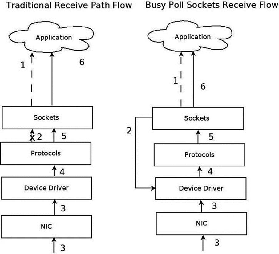
Figure 14-1. Traditional receive flow versus Busy Poll Sockets receive flow
1. Application checks for receive. 1. Application checks for receive
2. No immediate receive – thus block. 2. Check device driver for pending packet (poll starts).
3. Packet Received. 3. Meanwhile, packet received to NIC.
4. Driver passes packet to the protocol layer. 4. Driver processes pending packet
5. Protocol/socket wakes application. 5. Driver passes to the protocol layer
- Bypass context switch and interrupt.
6. Application receives data through sockets. 6. Application receives data through sockets.
Repeat. Repeat.
Enabling Globally
Busy Polling on Sockets can be turned on globally for all sockets via procfs parameters or it can be turned on for individual sockets by setting the SO_BUSY_POLL socket option. For global enabling, there are two parameters: net.core.busy_poll and net.core.busy_read, which are exported to procfs by /proc/sys/net/core/busy_poll and /proc/sys/net/core/busy_read, respectively. Both are zero by default, which means that Busy Polling is off. Setting these values will enable Busy Polling globally. A value of 50 will usually yield good results, but some experimentation might help find a better value for some applications.
· busy_read controls the time limit when busy polling on blocking read operations. For a non-blocking read, if busy polling is enabled for the socket, the stack code polls just once before returning control to the user.
· busy_poll controls how long select and poll will busy poll waiting for new events on any of the sockets that are enabled for Busy Polling. Only sockets with the busy read socket operation enabled are busy polled.
For more information, see: Documentation/sysctl/net.txt.
Enabling Per Socket
A better way to enable Busy Polling is to modify the application to use the SO_BUSY_POLL socket option, which sets the sk_ll_usec of the socket object (an instance of the sock structure). By using this socket option, an application can specify which sockets are Busy Polled so CPU utilization is increased only for those sockets. Sockets from other applications and services will continue to use the traditional receive path. The recommended starting value for SO_BUSY_POLL is 50. The sysctl.net.busy_read value must be set to 0 and thesysctl.net.busy_poll value should be set as described in Documentation/sysctl/net.txt.
Tuning and Configuration
Here are several ways in which you can tune and configure Busy Poll sockets:
· The interrupt coalescing (ethtool -C setting for rx-usecs) on the network device should be on the order of 100 to lower the interrupt rate. This limits the number of context switches caused by interrupts.
· Disabling GRO and LRO by using ethtool -K on the network device may avoid out of order packets on the receive queue. This should only be an issue when mixed bulk and low latency traffic arrive on the same queue. Generally, keeping GRO and LRO enabled usually gives best results.
· Application threads and the network device IRQs should be bound to separate CPU cores. Both sets of cores should be on the same CPU NUMA node as the network device. When the application and the IRQ run on the same core, there is a small penalty. If interrupt coalescing is set to a low value this penalty can be very large.
· For lowest latency, it may help to turn off the I/O Memory Management Unit (IOMMU) support. This may already be disabled by default on some systems.
Performance
Many applications that use Busy Polling Sockets should show reduced latency and jitter as well as improved transactions per second. However, overloading the system with too many sockets that are busy polling can hurt performance as CPU contention increases. The parametersnet.core.busy_poll, net.core.busy_read and the SO_BUSY_POLL socket option are all tunable. Experimenting with these values may give better results for various applications.
I will now start a discussion of three wireless subsystems, which typically serve short range and low power devices: the Bluetooth subsystem, IEEE 802.15.4 and NFC. There is a growing interest in these three subsystems as new exciting features are added quite steadily. I will start the discussion with the Bluetooth subsystem.
The Linux Bluetooth Subsystem
The Bluetooth protocol is one of the major transport protocols mainly for small and embedded devices. Bluetooth network interfaces are included nowadays in almost every new laptop or tablet and in every mobile phone, and in many electronic gadgets. The Bluetooth protocol was created by the mobile vendor Ericsson in 1994. In the beginning, it was intended to be a cable-replacement for point-to-point connections. Later, it evolved to enable wireless Personal Area Networks (PANs). Bluetooth operates in the 2.4 GHz Industrial, Scientific and Medical (ISM) radio-frequency band, which is license-free for low-power transmissions. The Bluetooth specifications are formalized by the Bluetooth Special Interest Group (SIG), which was founded in 1998; see https://www.bluetooth.org. The SIG is responsible for development of Bluetooth specification and for the qualification process that helps to ensure interoperability between Bluetooth devices from different vendors. The Bluetooth core specification is freely available. There were several specifications for Bluetooth over the years, I will mention the most recent:
· Bluetooth v2.0 + Enhanced Data Rate (EDR) from 2004.
· Bluetooth v2.1 + EDR 2007; included improvement of the pairing process by secure simple pairing (SSP).
· Bluetooth v3.0 + HS (High Speed) from 2009; the main new feature is AMP (Alternate MAC/PHY), the addition of 802.11 as a high-speed transport.
· Bluetooth v4.0 + BLE (Bluetooth Low Energy, which was formerly known as WiBree) from 2010.
There is a variety of uses for the Bluetooth protocol, like file transfer, audio streaming, health-care devices, networking, and more. Bluetooth is designed for short distance data exchange, in a range that typically extends up to 10 meters. There are three classes of Bluetooth devices, with the following ranges:
· Class 1 – about 100 m.
· Class 2 – about 10 m.
· Class 3 – about 1 m.
The Linux Bluetooth protocol stack is called BlueZ. Originally it was a project started by Qualcomm. It was officially integrated in kernel 2.4.6 (2001). Figure 14-2 shows the Bluetooth stack.
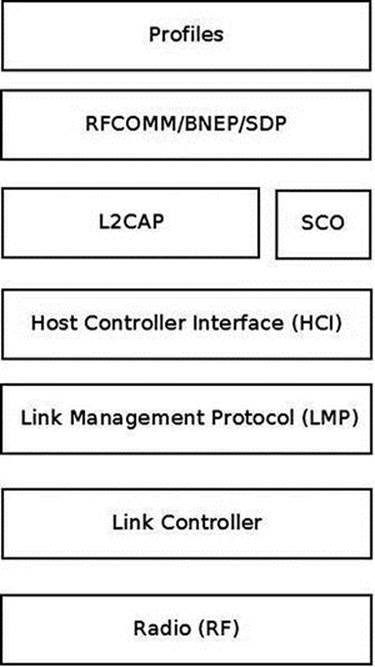
Figure 14-2. Bluetooth stack. Note: In the layer above L2CAP there can be other Bluetooth protocols that are not discussed in this chapter, like AVDTP (Audio/Video Distribution Transport Protocol), HFP (Hands-Free Profile), Audio/video control transport protocol (AVCTP), and more
· The lower three layers (The RADIO layer, Link controller and Link Management Protocol) are implemented in hardware or firmware.
· The Host Controller Interface (HCI) specifies how the host interacts and communicates with a local Bluetooth device (the controller). I will discuss it in the “HCI Layer” section, later in this chapter.
· The L2CAP (Logical link control and adaptation protocol) provides the ability to transmit and to receive packets from other Bluetooth devices. An application can use the L2CAP protocol as a message-based, unreliable data-delivery transport protocol similarly to the UDP protocol. Access to the L2CAP protocol from userspace is done by BSD sockets API, which was discussed in Chapter 11. Note that in L2CAP, packets are always delivered in the order they were sent, as opposed to UDP. In Figure 14-2, I showed three protocols that are located on top of L2CAP (there are other protocols on top of L2CAP that are not discussed in this chapter, as mentioned earlier).
· BNEP: Bluetooth Network Encapsulation Protocol. I will present an example of using the BNEP protocol later in this chapter.
· RFCOMM: The Radio Frequency Communications (RFCOMM) protocol is a reliable streams-based protocol. RFCOMM allows operation over only 30 ports. RFCOMM is used for emulating communication over a serial port and for sending unframed data.
· SDP: Service Discovery Protocol. Enables an application to register a description and a port number in an SDP server it runs. Clients can perform a lookup in the SDP server providing the description.
· The SCO (Synchronous Connection-Oriented) Layer: for sending audio; I do not delve into its details in this chapter as it falls outside the scope of this book.
· Bluetooth profiles are definitions of possible applications and specify general behaviors that Bluetooth- enabled devices use to communicate with other Bluetooth devices. There are many Bluetooth profiles, and I will mention some of the most commonly used ones:
· File Transfer Profile (FTP): Manipulates and transfers objects (files and folders) in an object store (file system) of another system.
· Health Device Profile (HDP): Handles medical data.
· Human Interface Device Profile (HID): A wrapper of USB HID (Human Interface Device) that provides support for devices like mice and keyboards.
· Object Push Profile (OPP) – Push objects profile.
· Personal Area Networking Profile (PAN): Provides networking over a Bluetooth link; you will see an example of it in the BNEP section later in this chapter.
· Headset Profile (HSP): Provides support for Bluetooth headsets, which are used with mobile phones.
The seven layers in this diagram are roughly parallel to the seven layers of the OS model. The Radio (RF) layer is parallel to the Physical layer, the Link Controller is parallel to the Data Link Layer, the Link Management Protocol is parallel to the Network Protocol, and so on. The Linux Bluetooth subsystem consists of several ingredients:
· Bluetooth Core
· HCI device and connection manager, scheduler; files: net/bluetooth/hci*.c, net/bluetooth/mgmt.c.
· Bluetooth Address Family sockets; file: net/bluetooth/af_bluetooth.c.
· SCO audio links; file: net/bluetooth/sco.c.
· L2CAP (Logical Link Control and Adaptation Protocol); files: net/bluetooth/l2cap*.c.
· SMP (Security Manager Protocol) on LE (Low Energy) links; file: net/bluetooth/smp.c
· AMP manager - Alternate MAC/PHY management; file: net/bluetooth/a2mp.c.
· HCI Device drivers (Interface to the hardware); files: drivers/bluetooth/*. Includes vendor specific drivers as well as generic drivers, like the Bluetooth USB generic driver, btusb.
· RFCOMM Module (RFCOMM Protocol); files: net/bluetooth/rfcomm/*.
· BNEP Module (Bluetooth Network Encapsulation Protocol); files: net/bluetooth/bnep/*.
· CMTP Module (CAPI Message Transport Protocol), used by the ISDN protocol. CMTP is in fact obsolete; files: net/bluetooth/cmtp/*.
· HIDP Module (Human Interface Device Protocol); files: net/bluetooth/hidp/*.
I discussed briefly the Bluetooth protocol, the architecture of the Bluetooth stack and the Linux Bluetooth subsystem tree, and Bluetooth profiles. In the next section I will describe the HCI layer, which is the first layer above the LMP (see Figure 14-2 earlier in this section).
HCI Layer
I will start the discussion of the HCI layer with describing the HCI device, which represents a Bluetooth controller. Later in this section I will describe the interface between the HCI layer and the layer below it, the Link Controller layer, and the interface between the HCI and the layers above it, L2CAP and SCO.
HCI Device
A Bluetooth device is represented by struct hci_dev. This structure is quite big (over 100 members), and will partially be shown here:
struct hci_dev {
char name[8];
unsigned long flags;
__u8 bus;
bdaddr_t bdaddr;
__u8 dev_type;
. . .
struct work_struct rx_work;
struct work_struct cmd_work;
. . .
struct sk_buff_head rx_q;
struct sk_buff_head raw_q;
struct sk_buff_head cmd_q;
. . .
int (*open)(struct hci_dev *hdev);
int (*close)(struct hci_dev *hdev);
int (*flush)(struct hci_dev *hdev);
int (*send)(struct sk_buff *skb);
void (*notify)(struct hci_dev *hdev, unsigned int evt);
int (*ioctl)(struct hci_dev *hdev, unsigned int cmd, unsigned long arg);
}
(include/net/bluetooth/hci_core.h)
Here is a description of some of the important members of the hci_dev structure:
· flags: Represents the state of a device, like HCI_UP or HCI_INIT.
· bus: The bus associated with the device, like USB (HCI_USB), UART (HCI_UART), PCI (HCI_PCI), etc. (see include/net/bluetooth/hci.h).
· bdaddr: Each HCI device has a unique address of 48 bits. It is exported to sysfs by: /sys/class/bluetooth/<hciDeviceName>/address
· dev_type: There are two types of Bluetooth devices:
· Basic Rate devices (HCI_BREDR).
· Alternate MAC and PHY devices (HCI_AMP).
· rx_work: Handles receiving packets that are kept in the rx_q queue of the HCI device, by the hci_rx_work() callback.
· cmd_work: Handles sending command packets which are kept in the cmd_q queue of the HCI device, by the hci_cmd_work() callback.
· rx_q: Receive queue of SKBs. SKBs are added to the rx_q by calling the skb_queue_tail() method when receiving an SKB, in the hci_recv_frame() method.
· raw_q: SKBs are added to the raw_q by calling the skb_queue_tail() method in the hci_sock_sendmsg() method.
· cmd_q: Command queue. SKBs are added to the cmd_q by calling the skb_queue_tail() method in the hci_sock_sendmsg() method.
The hci_dev callbacks (like open(), close(), send(), etc) are typically assigned in the probe() method of a Bluetooth device driver (for example, refer to the generic USB Bluetooth driver, drivers/bluetooth/btusb.c).
The HCI layer exports methods for registering/unregistering an HCI device (by the hci_register_dev() and the hci_unregister_dev() methods, respectively). Both methods get an hci_dev object as a single parameter. The registration will fail if the open() or close()callbacks of the specified hci_dev object are not defined.
There are five types of HCI packets:
· HCI_COMMAND_PKT: Commands sent from the host to the Bluetooth device.
· HCI_ACLDATA_PKT: Asynchronous data which is sent or received from a Bluetooth device. ACL stands for Asynchronous Connection-oriented Link (ACL) protocol.
· HCI_SCODATA_PKT: Synchronous data which is sent or received from a Bluetooth device (usually audio). SCO stands for Synchronous Connection-Oriented (SCO).
· HCI_EVENT_PKT: Sent when an event (such as connection establishment) occurs.
· HCI_VENDOR_PKT: Used in some Bluetooth device drivers for vendor specific needs.
HCI and the Layer Below It (Link Controller)
The HCI communicates with the layer below it, the Link Controller, by:
· Sending data packets (HCI_ACLDATA_PKT or HCI_SCODATA_PKT) by calling the hci_send_frame() method, which delegates the call to the send() callback of the hci_dev object. The hci_send_frame() method gets an SKB as a single parameter.
· Sending command packets (HCI_COMMAND_PKT), by calling the hci_send_cmd() method. For example, sending a scan command.
· Receiving data packets, by calling the hci_acldata_packet() method or by calling the hci_scodata_packet() method.
· Receiving event packets, by calling the hci_event_packet() method. Handling HCI commands is asynchronous; so some time after sending a command packet (HCI_COMMAND_PKT), a single event or several events are received as a response by the HCIrx_work work_queue (the hci_rx_work() method). There are more than 45 different events (see HCI_EV_* in include/net/bluetooth/hci.h). For example, when performing a scan for nearby Bluetooth devices using the command-line hcitool, byhcitool scan, a command packet (HCI_OP_INQUIRY) is sent. As a result, three event packets are returned asynchronously to be handled by the hci_event_packet() method: HCI_EV_CMD_STATUS, HCI_EV_EXTENDED_INQUIRY_RESULT, and HCI_EV_INQUIRY_COMPLETE.
HCI and the Layers Above It (L2CAP/SCO)
Let’s take a look at the methods by which the HCI layer communicates with the layers above it, the L2CAP layer and the SCO layer:
· HCI communicates with the L2CAP layer above it when receiving data packets by calling the hci_acldata_packet() method, which invokes the l2cap_recv_acldata() method of the L2CAP protocol.
· HCI communicates with the SCO layer above it when receiving SCO packets by calling the hci_scodata_packet() method, which invokes the sco_recv_scodata() method of the SCO protocol.
HCI Connection
The HCI connection is represented by the hci_conn structure:
struct hci_conn {
struct list_head list;
atomic_t refcnt;
bdaddr_t dst;
. . .
__u8 type;
}
(include/net/bluetooth/hci_core.h)
The following is a description of some of the members of the hci_conn structure:
· refcnt: A reference counter.
· dst: The Bluetooth destination address.
· type: Represents the type of the connection:
· SCO_LINK for SCO connection.
· ACL_LINK for ACL connection.
· ESCO_LINK for Extended Synchronous connection.
· LE_LINK – represents LE (Low Energy) connection; was added in kernel v2.6.39 to support Bluetooth V4.0, which added the LE feature.
· AMP_LINK – Added in v3.6 to support Bluetooth AMP controllers.
An HCI connection is created by calling the hci_connect() method. There are three types of connections: SCO, ACL, and LE connection.
L2CAP
In order to provide several data streams, L2CAP uses channels, which are represented by the l2cap_chan structure (include/net/bluetooth/l2cap.h). There is a global linked list of channels, named chan_list. Access to this list is serialized by a global read-write lock,chan_list_lock.
The l2cap_recv_acldata() method, which I described in the section “HCI and the layers above it (L2CAP/SCO)” earlier in this chapter, is called when HCI passes data packets to the L2CAP layer. The l2cap_recv_acldata() method first performs some sanity checks and drops the packet if something is wrong, then it invokes the l2cap_recv_frame() method in case a complete packet was received. Each received packet starts with an L2CAP header:
struct l2cap_hdr {
__le16 len;
__le16 cid;
} __attribute__ ((packed));
(include/net/bluetooth/l2cap.h)
The l2cap_recv_frame() method checks the channel id of the received packet by inspecting the cid of the l2cap_hdr object. In case it is an L2CAP command (the cid is 0x0001) the l2cap_sig_channel() method is invoked to handle it. For example, when another Bluetooth device wants to connect to our device, an L2CAP_CONN_REQ request is received on the L2CAP signal channel, which will be handled by the l2cap_connect_req() method, net/bluetooth/l2cap_core.c. In the l2cap_connect_req() method, an L2CAP channel is created by calling the l2cap_chan_create() method, via pchan->ops->new_connection(). The L2CAP channel state is set to be BT_OPEN, and the configuration state is set to be CONF_NOT_COMPLETE. This means that the channel should be configured in order to work with it.
BNEP
The BNEP protocol enables IP over Bluetooth, which means in practical terms running TCP/IP applications on top of L2CAP Bluetooth channels. You can also run TCP/IP applications with PPP over Bluetooth RFCOMM, but networking over serial PPP link is less efficient. The BNEP protocol uses a PAN profile. I will show a short example of using the BNEP protocol to setup Bluetooth over IP, and subsequently I will describe the kernel methods which implement such communication. Delving into the details of BNEP is beyond the scope of this book. If you want to learn more, see the BNEP spec, which can be found in: http://grouper.ieee.org/groups/802/15/Bluetooth/BNEP.pdf. A very simple way to create a PAN is by running:
· On the server side:
· pand --listen --role=NAP
· Note: NAP stands for: Network Access Point (NAP)
· On the client side
· pand --connect btAddressOfTheServer
On both endpoints, a virtual interface (bnep0) is created. Afterward, you can assign an IP addresses on bnep0 for both endpoints with the ifconfig command (or with the ip command), just like with Ethernet devices, and you will have a network connection over Bluetooth between these endpoints. See more in http://bluez.sourceforge.net/contrib/HOWTO-PAN.
The pand --listen command creates an L2CAP server socket, and calls the accept() system call, whereas the pand --connect btAddressOfTheServer creates an L2CAP client socket and calls the connect() system call. When the connect request is received in the server side, it sends an IOCTL of BNEPCONNADD, which is handled in the kernel by the bnep_add_connection() method (net/bluetooth/bnep/core.c), which performs the following tasks:
· Creates a BNEP session (bnep_session object).
· Adds the BNEP session object to the BNEP session list (bnep_session_list) by calling the __bnep_link_session() method.
· Creates a network device named bnepX (for the first BNEP device X is 0, for the second X is 1, and so on).
· Registers the network device by calling the register_netdev() method.
· Creates a kernel thread named “kbnepd btDeviceName”. This kernel thread runs the bnep_session() method which contains an endless loop, to receive or transmit packets. This endless loop terminates only when a userspace application sends an IOCTL of BNEPCONNDEL, which calls the method bnep_del_connection() to set the terminate flag of the BNEP session, or when the state of the socket is changed and it is not connected anymore.
· The bnep_session() method invokes the bnep_rx_frame() method to receive incoming packets and to pass them to the network stack, and it invokes the bnep_tx_frame() method to send outgoing packets.
Receiving Bluetooth Packets: Diagram
Figure 14-3 shows the path of a received Bluetooth ACL packet (as opposed to SCO, which is for handling audio and is handled differently). The first layer where the packet is handled is the HCI layer, by the hci_acldata_packet() method. It then proceeds to the higher L2CAP layer by calling the l2cap_recv_acldata() method.
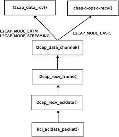
Figure 14-3. Receiving an ACL packet
The l2cap_recv_acldata() method calls the l2cap_recv_frame() method, which fetches the L2CAP header (the l2cap_hdr object was described earlier) from the SKB.
An action is being taken according to the channel ID of the L2CAP header.
L2CAP Extended Features
Support for L2CAP Extended Features (also called eL2CAP) was added in kernel 2.6.36. These extended features include:
· Enhanced Retransmission Mode (ERTM), a reliable protocol with error and flow control.
· Streaming Mode (SM), an unreliable protocol for streaming purposes.
· Frame Check Sequence (FCS), a checksum for each received packet.
· Segmentation and Reassembly (SAR) of L2CAP packets that make retransmission easier.
Some of these extensions were required for new profiles, like the Bluetooth Health Device Profile (HDP). Note that these features were available also before, but they were considered experimental and were disabled by default, and you should have set CONFIG_BT_L2CAP_EXT_FEATURES to enable them.
Bluetooth Tools
Accessing the kernel from userspace is done with sockets with minor changes: instead of using AF_INET sockets, we use AF_BLUTOOTH sockets. Here is a short description of some important and useful Bluetooth tools:
· hciconfig: A tool for configuring Bluetooth devices. Displays information such as the interface type (BR/EDR or AMP), its Bluetooth address, its flags, and more. The hciconfig tool works by opening a raw HCI socket (BTPROTO_HCI) and sending IOCTLs; for example, in order to bring up or bring down the HCI device, an HCIDEVUP or HCIDEVDOWN is sent, respectively. These IOCTLs are handled in the kernel by the hci_sock_ioctl() method, net/bluetooth/hci_sock.c.
· hcitool: A tool for configuring Bluetooth connections and sending some special command to Bluetooth devices. For example hcitool scan will scan for nearby Bluetooth devices.
· hcidump: Dump raw HCI data coming from and going to a Bluetooth device.
· l2ping: Send an L2CAP echo request and receive answer.
· btmon: A friendlier version of hcidump.
· bluetoothctl: A friendlier version of hciconfig/hcitool.
You can find more information about the Linux Bluetooth subsystem in:
· Linux BlueZ, the official Linux Bluetooth website:http://www.bluez.org.
· Linux Bluetooth mailing list: linux-bluetooth@vger.kernel.org.
· Linux Bluetooth mailing list archives: http://www.spinics.net/lists/linux-bluetooth/.
· Note that this mailing list is for Bluetooth kernel patches as well as Bluetooth userspace patches.
· IRC channels on freenode.net:
· #bluez (development related topics)
· #bluez-users (non-development related topics)
In this section I described the Linux Bluetooth subsystem, focusing on the networking aspects of this subsystem. You learned about the layers of the Bluetooth stack and how they are implemented in the Linux kernel. You also learned about the important Bluetooth kernel structures like HCI device and HCI connection. Next, I will describe the second wireless subsystem, the IEEEE 802.15.4 subsystem, and its implementation.
IEEE 802.15.4 and 6LoWPAN
The IEEE 802.15.4 standard (IEEE Std 802.15.4-2011) specifies the Medium Access Control (MAC) layer and Physical (PHY) layer for Low-Rate Wireless Personal Area Networks (LR-WPANs). It is intended for low-cost and low-power consumption devices in a short-range network. Several bands are supported, among which the most common are the 2.4 GHz ISM band, 915 MHz, and 868 MHz. IEEE 802.15.4 devices can be used for example in wireless sensor networks (WSNs), security systems, industry automation systems, and more. It was designed to organize networks of sensors, switches, automation devices, etc. The maximum allowed bit rate is 250 kb/s. The standard also supports a 1000 kb/s bit rate for the 2.4 GHz band, but it is less common. Typical personal operating space is around 10m. The IEEE 802.15.4 standard is maintained by the IEEE 802.15 working group (http://www.ieee802.org/15/). There are several protocols which sit on top of IEEE 802.15.4; the most known are ZigBee and 6LoWPAN.
The ZigBee Alliance (ZA) has published non GPL specifications for IEEE802.15.4, but also the ZigBee IP (Z-IP) open standard (http://www.zigbee.org/Specifications/ZigBeeIP/Overview.aspx). It is based on Internet protocols such as IPv6, TCP, UDP, 6LoWPAN, and more. Using the IPv6 protocol for IEEE 802.15.4 is a good option because there is a huge address space of IPv6 addresses, which makes it possible to assign a unique routable address to each IPv6 node. The IPv6 header is simpler than the IPv4 header, and processing its extension headers is simpler than processing IPv4 header options. Using IPv6 with LR-WPANs is termed IPv6 over Low-power Wireless Personal Area Networks (6LoWPAN). IPv6 is not adapted for its use on an LR-WPAN and therefore requires an adaptation layer, as will be explained later in this section. There are five RFCs related to 6LoWPAN:
· RFC 4944: “Transmission of IPv6 Packets over IEEE 802.15.4 Networks.”
· RFC 4919: “IPv6 over Low-Power Wireless Personal Area Networks (6LoWPANs): Overview, Assumptions, Problem Statement, and Goals.”
· RFC 6282: “Compression Format for IPv6 Datagrams over IEEE 802.15.4-Based Networks.” This RFC introduced a new encoding format, the LOWPAN_IPHC Encoding Format, instead of LOWPAN_HC1 and LOWPAN_HC2.
· RFC 6775: “Neighbor Discovery Optimization for IPv6 over Low-Power Wireless Personal Area Networks (6LoWPANs).”
· RFC 6550: “RPL: IPv6 Routing Protocol for Low-Power and Lossy Networks.”
The main challenges for implementing 6LoWPAN are:
· Different packet sizes: IPv6 has MTU of 1280 whereas IEEE802.15.4 has an MTU of 127 (IEEE802154_MTU). In order to support packets larger than 127 bytes, an adaptation layer between IPv6 and IEEE 802.15.4 should be defined. This adaptation layer is responsible for the transparent fragmentation/defragmentation of IPv6 packets.
· Different addresses: IPv6 address is 128 bit whereas IEEE802.15.4 are IEEE 64-bit extended (IEEE802154_ADDR_LONG) or, after association and after a PAN id is assigned, a 16 bit short addresses (IEEE802154_ADDR_SHORT) which are unique in that PAN. The main challenge is that we need compression mechanisms to reduce the size of a 6LoWPAN packet, largely made up of the IPv6 addresses. 6LoWPAN can for example leverage the fact that IEEE802.15.4 supports 16 bits short addresses to avoid the need of a 64-bit IID.
· Multicast is not supported natively in IEEE 802.15.4 whereas IPv6 uses multicast for ICMPv6 and for protocols that rely on ICMPv6 like the Neighbour Discovery protocol.
IEEE 802.15.4 defines four types of frames:
· Beacon frames (IEEE802154_FC_TYPE_BEACON)
· MAC command frames (IEEE802154_FC_TYPE_MAC_CMD)
· Acknowledgement frames (IEEE802154_FC_TYPE_ACK)
· Data frames (IEEE802154_FC_TYPE_DATA)
IPv6 packets must be carried on the fourth type, data frames. Acknowledgment for data packets is not mandatory, although it is recommended. As with 802.11, there are device drivers that implement most parts of the protocol by themselves (HardMAC device drivers), and device drivers that handle most of the protocol in software (SoftMAC device drivers). There are three types of nodes in 6LoWPAN:
· 6LoWPAN Node (6LN): Either a host or a router.
· 6LoWPAN Router (6LR): can send and receive Router Advertisements (RA) and Router Solicitations (RS) messages as well as forward and route IPv6 packets. These nodes are more complex than simple 6LoWPAN nodes and may need more memory and processing capacity.
· 6LoWPAN Border Router (6LBR): A border router located at the junction of separate 6LoWPAN networks or between a 6LoWPAN network and another IP network. The 6LBR is responsible for Forwarding between the IP network and the 6LoWPAN network and for the IPv6 configuration of the 6LoWPAN nodes. A 6LBR requires much more memory and processing capacity than a 6LN. They share context for the nodes in the LoWPAN, keep track of registered nodes with 6LoWPAN-ND and RPL. Generally 6LBR is always-on in contrast to 6LN who sleep most of their times. Figure 14-4 shows a simple setup with 6LBR, which connects between an IP network and a Wireless Sensor Network based on 6LoWPAN.
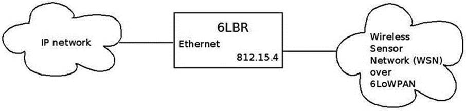
Figure 14-4. 6LBR connecting an IP network to WSN which runs over 6LoWPAN
Neighbor Discovery Optimization
There are two reasons we should have optimizations and extensions for the IPv6 Neighboring protocol:
· IEEE 802.15.4 link layer does not have multicast support, although it supports broadcast (it uses 0xFFFF short address for message broadcasting).
· The Neighbor Discovery protocol is designed for sufficiently powered devices, and IEEE 802.15.4 devices can sleep in order to preserve energy; moreover, they operate in a lossy network environment, as the RFC puts it.
RFC 6775, which deals with Neighbor Discovery Optimization, added new optimizations such as:
· Host-initiated refresh of Router Advertisement information. In IPv6, routers usually send periodically Router Advertisements. This feature removes the need for periodic or unsolicited Router Advertisements sent from routers to hosts.
· EUI-64-based IPv6 addresses are considered to be globally unique. When such addresses are used, DAD (Duplicate Address Detection) is not needed.
· Three options were added:
· Address Registration Option (ARO): The ARO option (33) can be a part of unicast NS message that a host sends as part of NUD (Neighbor Unreachability Detection) to determine that it can still reach a default router. When a host has a non-link-local address, it sends periodically NS messages to its default routers with the ARO options in order to register its address. Unregistration is done by sending an NS with an ARO containing a lifetime of 0.
· 6LoWPAN Context Option (6CO): The 6CO option (34) carries prefix information for LoWPAN header compression, and is similar to Prefix Information option (PIO) which is specified in RFC 4861.
· Authoritative Border Router Option (ABRO): The ABRO option (35) enables disseminating prefixes and context information across a route-over topology.
· Two new DAD messages were added:
· Duplicate Address Request (DAR). New ICMPv6 type of 157.
· Duplicate Address Confirmation (DAC). New ICMPv6 type of 158.
Linux Kernel 6LoWPAN
The 6LoWPAN basic implementation was integrated into v3.2 Linux. It was contributed by the Embedded Systems Open Platform Group, from Siemens Corporate Technology. It has three layers:
· Network layer - net/ieee802154 (includes the 6lowpan module, Raw IEEE 802.15.4 sockets, the netlink interface, and more).
· MAC layer - net/mac802154. Implements a partial MAC layer for SoftMAC device drivers.
· PHY layer - drivers/net/ieee802154 – the IEEE802154 device drivers.
· There are currently two 802.15.4 devices which are supported:
· AT86RF230/231 transceiver driver
· Microchip MRF24J40
· There is the Fakelb driver (IEEE 802.15.4 loopback interface).
· These two devices, as well as many other 802.15.4 transceivers, are connected via SPI. There is also a serial driver, although it is not included in the mainline kernel and still experimental. There are devices like atusb, which are based on an AT86RF231 BN but are not in mainline as of this writing.
6LoWPAN Initialization
In the lowpan_init_module() method, initialization of 6LoWPAN netlink sockets is done by calling the lowpan_netlink_init() method, and a protocol handler is registered for 6LoWPAN packets by calling the dev_add_pack() method:
. . .
static struct packet_type lowpan_packet_type = {
.type = __constant_htons(ETH_P_IEEE802154),
.func = lowpan_rcv,
};
. . .
static int __init lowpan_init_module(void)
{
. . .
dev_add_pack(&lowpan_packet_type);
. . .
}
(net/ieee802154/6lowpan.c)
The lowpan_rcv() method is the main Rx handler for 6LoWPAN packets, which has an ethertype of 0x00F6 (ETH_P_IEEE802154). It handles two cases:
· Reception of uncompressed packets (dispatch type is IPv6.)
· Reception of compressed packets.
You use a virtual link to ensure the translation between 6LoWPAN and IPv6 packets. One endpoint of this virtual link speaks IPv6 and has an MTU of 1280, this is the 6LoWPAN interface. The other one speaks 6LoWPAN and has an MTU of 127, this is the WPAN interface. Compressed 6LoWPAN packets are processed by the lowpan_process_data() method, which calls the lowpan_uncompress_addr() to uncompress addresses and the lowpan_uncompress_udp_header() to uncompress the UDP header accordingly to the IPHC header. The uncompressed IPv6 packet is then delivered to the 6LoWPAN interface with the lowpan_skb_deliver() method (net/ieee802154/6lowpan.c).
Figure 14-5 shows the 6LoWPAN Adaptation layer.
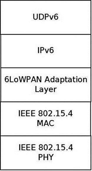
Figure 14-5. 6LoWPAN Adaptation layer
Figure 14-6 shows the path of a packet from the PHY layer (the driver) via the MAC layer to the 6LoWPAN adaptation layer.
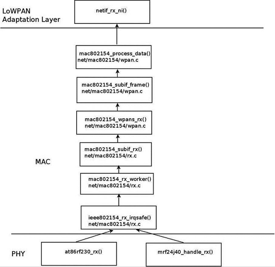
Figure 14-6. Receiving a packet
I will not delve into the details of the device drivers implementation, as this is out of our scope. I will mention that each device driver should create an ieee802154_dev object by calling the ieee802154_alloc_device() method, passing as a parameter an ieee802154_opsobject. Every driver should define some ieee802154_ops object callbacks, like xmit, start, stop, and more. This applies for SoftMAC drivers only.
I will mention here that an Internet-Draft was submitted for applying 6LoWPAN technology over Bluetooth Low-Energy devices (these devices are part of the Bluetooth 4.0 specification, as was mentioned in the previous chapter). See “Transmission of IPv6 Packets over Bluetooth Low Energy,” http://tools.ietf.org/html/draft-ietf-6lowpan-btle-12.
![]() Note Contiki is an open source Operating System implementing the Internet of Things (IoT) concept; some patches of the Linux IEEE802.15.4 6LoWPAN are derived from it, like the UDP header compression and decompression. It implements 6LoWPAN, and RPL. It was developed by Adam Dunkels. See http://www.contiki-os.org/
Note Contiki is an open source Operating System implementing the Internet of Things (IoT) concept; some patches of the Linux IEEE802.15.4 6LoWPAN are derived from it, like the UDP header compression and decompression. It implements 6LoWPAN, and RPL. It was developed by Adam Dunkels. See http://www.contiki-os.org/
For additional resources about 6LoWPAN and 802.15.4:
· Books:
· “6LoWPAN: The Wireless Embedded Internet”, by Zach Shelby and Carsten Bormann, Wiley, 2009.
· “Interconnecting Smart Objects with IP: The Next Internet,” by Jean-Philippe Vasseur and Adam Dunkels (the Contiki developer), Morgan Kaufmann, 2010.
· An article about IPv6 Neighbor Discovery Optimization: http://www.internetsociety.org/articles/ipv6-neighbor-discovery-optimization.
The lowpan-tools is a set of utilities to manage the Linux LoWPAN stack. See: http://sourceforge.net/projects/linux-zigbee/files/linux-zigbee-sources/0.3/
![]() Note The IEEE802.15.4 does not maintain a git repository of its own (though in the past there was one). Patches are sent to the netdev mailing list; some of the developers send the patches first to the linux zigbee developer mailing list to get some feedback:https://lists.sourceforge.net/lists/listinfo/linux-zigbee-devel
Note The IEEE802.15.4 does not maintain a git repository of its own (though in the past there was one). Patches are sent to the netdev mailing list; some of the developers send the patches first to the linux zigbee developer mailing list to get some feedback:https://lists.sourceforge.net/lists/listinfo/linux-zigbee-devel
I described the IEEE 802.15.4 and the 6LoWPAN protocol in this section and the challenges it poses for integration in the Linux kernel, like adding Neighboring Discovery messages. In the next section I will describe the third wireless subsystem, which is intended for the most shortest ranges among the three wireless subsystems described in this chapter: the Near Field Communication (NFC) subsystem.
Near Field Communication (NFC)
Near Field Communication is a very short range wireless technology (less than two inches) designed to transfer small amount of data over a very low latency link at up to 424 kb/s. NFC payloads range from very simple URLs or raw texts to more complex out of band data to trigger connection handover. Through its very short range and latency, NFC implements a tap and share concept by linking proximity to an immediate action triggered by the NFC data payload. Touch an NFC tag with your NFC enabled mobile phone and this will, for example, immediately fire up a web browser.
NFC runs on the 13.65MHz band and is based on the Radio Frequency ID (RFID) ISO14443 and FeliCa standards. The NFC Forum (http://www.nfc-forum.org/) is a consortium responsible for standardizing the technology through a set of specifications, ranging from the NFC Digital layer up to high-level services definitions like the NFC Connection Handover or the Personal Health Device Communication (PHDC) ones. All adopted NFC Forum specifications are available free of charge. See http://www.nfc-forum.org/specs/.
At the heart of the NFC Forum specification is the NFC Data Exchange Format (NDEF) definition. It defines the NFC data structure used to exchange NFC payloads from NFC tags or between NFC peers. All NDEFs contain one or more NDEF Records that embed the actual payload. NDEF record header contains metadata that allow applications to build the semantic link between the NFC payload and an action to trigger on the reader side.
NFC Tags
NFC tags are cheap, mostly static and battery less data containers. They’re typically made of an inductive antenna connected to a very small amount of flash memory, packaged in many different form factors (labels, key rings, stickers, etc.). As per the NFC Forum definitions, NFC tags are passive devices, i.e., they’re unable to generate any radio field. Instead they’re powered by NFC active devices initiated RF fields. The NFC Forum defines four different tag types, each of them carrying a strong RFID and smart card legacy:
· Type 1 specifications derive from Innovision/Broadcom Topaz and Jewel card specifications. They can expose from 96 up to 2 KBytes of data at 106 kb/s.
· Type 2 tags are based on NXP Mifare Ultralight specifications. They’re very similar to Type 1 tags.
· Type 3 tags are built on top of the non-secure parts of Sony FeliCa tags. They’re more expensive than Type 1 and 2 tags, but can carry up to 1 MBytes at 212 or 424 kb/s.
· Type 4 specifications are based on NXP DESFire cards, support up to 32 KBytes and three transmission speeds: 106, 212, or 424 kb/s.
NFC Devices
As opposed to NFC tags, NFC devices can generate their own magnetic field to initiate NFC communications. NFC-enabled mobile phones and NFC readers are the most common kinds of NFC devices. They support a larger feature set than NFC tags. They can read from or write to NFC tags, but they can also pretend to be a card and be seen as simple NFC tags from any reader. But one of the key advantages of the NFC technology over RFID is the possibility to have two NFC devices talking to each other in an NFC specific peer-to-peer mode. The link between two NFC devices is kept alive as long as the two devices are in magnetic range. In practice this means two NFC devices can maintain a peer-to-peer link while they physically touch each other. This introduces a whole new range of mobile use cases where one can exchange data, context, or credentials by touching someone else NFC device.
Communication and Operation Modes
The NFC Forum defines two communication and three operation modes. An active NFC communication is established when two NFC devices can talk to one another by alternatively generating the magnetic field. This implies that both devices have their own power supply as they don’t rely on any inductively generated power. Active communications can only be established in NFC peer-to-peer mode. On the other hand, only one NFC device generates the radio field on a passive NFC communication, and the other device replies by using that field.
There are three NFC operation modes:
· Reader/Writer: An NFC device (e.g., an NFC-enabled mobile phone) read from or write to an NFC tag.
· Peer-to-peer: Two NFC devices establish a Logical Link Control Protocol (LLCP) over which several NFC services can be multiplexed: Simple NDEF Exchange Protocol (SNEP) for exchanging NDEF formatted data, Connection Handover for initiating a carrier (Bluetooth or WiFi) handover, or any proprietary protocol.
· Card Emulation: An NFC device replies to a reader poll by pretending to be an NFC tag. Payment and transaction issuers rely on this mode to implement contactless payments on top of NFC. In card emulation mode, payment applets running on a trusted execution environment (also known as “secure elements”) take control of the NFC radio and expose themselves as a legacy payment card that can be read from an NFC-enabled point-of-sale terminal.
Host-Controller Interfaces
Communication between hardware controllers and host stacks must follow a precisely defined interface: the host-controller one (HCI). The NFC hardware ecosystem is quite fragmented in that regard, as most of the initial NFC controllers implement an ETSI specified HCI originally designed for communication between SIM cards and contactless front-ends. (See http://www.etsi.org/deliver/etsi_ts/102600_102699/102622/07.00.00_60/ts_102622v070000p.pdf). This HCI was not tailored for NFC specific use cases, and so each and every manufacturer defined a large number of proprietary extensions to support their features. The NFC Forum tries to address that situation by defining its own interface, much more NFC oriented, the NFC Controller Interface (NCI). The industry trend is clearly showing that manufacturers abandon ETSI HCI in favor of NCI, building a more standardized hardware ecosystem.
Linux NFC support
Unlike the Android operating system NFC stack, which is described later in this section, the standard Linux one is partly implemented by the kernel itself. Since the 3.1 Linux kernel release, Linux based application will find an NFC specific socket domain, along with a generic netlink family for NFC. (See http://git.kernel.org/?p=linux/kernel/git/sameo/nfc-next.git;a=shortlog;h=refs/heads/master.) The NFC generic netlink family is intended to be an NFC out of band channel for controlling and monitoring NFC adapters. The NFC socket domain supports two families:
· Raw sockets for sending NFC frames that will arrive unmodified to the drivers
· LLCP sockets for implementing NFC peer-to-peer services
The hardware abstraction is implemented in NFC kernel drivers that register against various parts of the stack, mostly depending on the host-controller interface used by the controllers they support. As a consequence, Linux applications can work on top of a hardware agnostic and fully POSIX compatible NFC kernel APIs. The Linux NFC stack is split between kernel and userspace. The kernel NFC sockets allow userspace applications to implement NFC tags support by sending tag types specific commands through the raw protocol. NFC peer-to-peer protocols (SNEP, Connection Handover, PHDC, etc.) can be implemented by transmitting their specific payloads through NFC sockets as well. Finally, card emulation mode is built on top of the secure element parts of the kernel NFC netlink API. The Linux NFC daemon, neard, sits on top of the kernel and implements all three NFC modes, regardless of the NFC controller physically wired to the host platform. (See https://01.org/linux-nfc/.)
Figure 14-7 shows an overview of the NFC system.

Figure 14-7. NFC overview
NFC Sockets
NFC sockets are of two kinds: raw and LLCP. Raw NFC sockets were designed with reader mode support in mind, as they provide a way to transmit tag specific commands and receive the tag replies back. The neard daemon uses NFC Raw sockets to implement all four tag types support, in both reader and writer modes. LLCP sockets implement the NFC peer-to-peer logical link control protocol on top of which neard implements all NFC Forum specified peer-to-peer services (SNEP, Connection Handover, and PHDC).
Depending on the selected protocol, NFC socket semantics differ.
Raw Sockets
· connect: Select and enable a detected NFC tag
· bind: Not supported
· send/recv: Send and receive raw NFC payloads. The NFC core implementation does not modify those payloads.
LLCP Sockets
· connect: Connect to a specific LLCP service on a detected peer device, like the SNEP or Connection Handover services.
· bind: Link a device to a specific LLCP service. The service will be exported through the LLCP service name lookup (SNL) protocol for any NFC peer device to attempt a connection to it.
· send/recv: Transmit LLCP service payloads to and from an NFC peer device. The kernel will handle the LLCP specific link layer encapsulation and fragmentation.
· LLCP transport can be connected or connectionless, and this is handled through the UNIX standard SOCK_STREAM and SOCK_DGRAM socket types. NFC LLCP sockets also support the SOCK_RAW type for monitoring and sniffing purposes.
NFC Netlink API
The NFC generic netlink API is designed to implement out of band NFC specific operations. It also handles any discoverable secure element from an NFC controller. Through NFC netlink commands, you can:
· List all available NFC controllers.
· Power NFC controllers up and down.
· Start (and stop) NFC polls for discovering NFC tags and devices.
· Enable NFC peer-to-peer (a.k.a. LLCP) links between the local controller and remote NFC peers.
· Send LLCP service name lookup requests, in order to discover the available LLCP services on a remote peer.
· Enable and disable NFC discoverable secure elements (typically SIM card based or embedded secure elements).
· Send ISO7816 frames to enabled secure elements.
· Trigger NFC controller firmware downloads.
The netlink API is not only about sending synchronous commands from NFC applications, but also about receiving asynchronous NFC-related events. Applications listening for broadcast NFC events on an NFC netlink socket will get notified about:
· Detected NFC tags and devices
· Discovered secure elements
· Secure element transaction status
· LLCP service name lookup replies
The entire netlink API (both commands and events) along with the socket one are exported through the kernel headers, and installed at /usr/include/linux/nfc.h on standard Linux distributions.
NFC Initialization
NFC initialization is done by the nfc_init() method:
static int __init nfc_init(void)
{
int rc;
. . .
Register the generic netlink NFC family and the NFC notifier callback, the nfc_genl_rcv_nl_event() method:
rc = nfc_genl_init();
if (rc)
goto err_genl;
/* the first generation must not be 0 */
nfc_devlist_generation = 1;
Initialize NFC Raw sockets:
rc = rawsock_init();
if (rc)
goto err_rawsock;
Initialize NFC LLCP sockets:
rc = nfc_llcp_init();
if (rc)
goto err_llcp_sock;
Initialize the AF_NFC protocol:
rc = af_nfc_init();
if (rc)
goto err_af_nfc;
return 0;
. . .
}
(net/nfc/core.c)
Drivers API
As explained earlier, most NFC controllers nowadays either use HCI or NCI as their host-controller interface. Others define their proprietary interface over USB, like most PC-compatible NFC readers, for example. There are also some “Soft” NFC controllers that expect the host platform to implement the NFC Forum Digital layer and talk to an analog-only capable firmware. In order to support this variety of hardware controllers, the NFC kernel implements NFC NCI, HCI, and Digital layers. Depending on the NFC hardware they intend to support, device driver developers will need to register at module probing time against one of these stacks, or directly against the NFC core implementation for purely proprietary protocols. When registering, they typically provide a stack operands implementation, which is the actual hardware abstraction layer between NFC kernel drivers and the core parts of the NFC stack. The NFC driver registration APIs and operand prototypes are defined in the kernel include/net/nfc/ directory.
Figure 14-8 shows a block diagram of the NFC Linux Architecture.

Figure 14-8. NFC Linux Kernel Architecture. (Note that the NFC Digital layer is not in kernel 3.9. It is to be integrated into kernel 3.13.)
The hierarchy shown in this figure can be understood better by looking into the implementation details of the registration of NFC device drivers directly to the NFC core and against the HCI and the NCI layer:
· Registration directly against the NFC core is done typically in the driver probe() callback. The registration is done using these steps:
· Create an nfc_dev object by calling the nfc_allocate_device() method.
· Call the nfc_register_device() method, passing the nfc_dev object which was created in the previous step as a single parameter.
· See: drivers/nfc/pn533.c.
· Registration against the HCI layer is done typically also in the probe() callback of the driver; in the case of the pn544 and microread NFC device drivers, which are the only HCI drivers in kernel 3.9, this probe() method is invoked by the I2C subsystem. The registration is done using these steps:
· Create an nfc_hci_dev object by calling the nfc_hci_allocate_device() method.
· The nfc_hci_dev structure is defined in include/net/nfc/hci.h.
· Call the nfc_hci_register_device() method, passing the nfc_hci_dev object which was created in the previous step as a single parameter. The nfc_hci_register_device() method in turn performs a registration against the NFC core by calling the nfc_register_device() method.
· See drivers/nfc/pn544/pn544.c and drivers/nfc/microread/microread.c.
· Registration against the NCI layer is done typically also in the probe() callback of the driver, for example in the nfcwilink driver. The registration is done using these steps:
· Create an nci_dev object by calling the nci_allocate_device() method.
· The nci_dev structure is defined in include/net/nfc/nci_core.h.
· Call the nci_register_device() method, passing the nci_dev object that was created in the previous step as a single parameter. The nci_register_device() method in turn performs a registration against the NFC core by calling thenfc_register_device() method, similarly to what you saw earlier in this section with registration against the HCI layer.
· See drivers/nfc/nfcwilink.c.
When working directly against the NFC core, the driver must define five callbacks in the nfs_ops object (this object is passed as a first parameter of the nfc_allocate_device() method):
· start_poll: Set the driver to work in polling mode.
· stop_poll: Stop polling.
· activate_target: Activate a chosen target.
· deactivate_target: Deactivate a chosen target.
· im_transceive: Transceive operation.
When working with HCI , the hci_nfc_ops object, which is an instance of nfs_ops, defines these five callbacks, and when allocating an HCI object with the nfc_hci_allocate_device() method, the nfc_allocate_device() method is invoked with thishci_nfc_ops object as a first parameter.
With NCI, there is something quite similar, with the nci_nfc_ops object; see: net/nfc/nci/core.c.
Userspace Architecture
neard (http://git.kernel.org/?p=network/nfc/neard.git;a=summary) is the Linux NFC daemon that runs on top of the kernel NFC APIs. It is a single threaded, GLib based process that implements the higher layers of the NFC peer-to-peer stack along with the four tag types specific commands for reading from and writing to NFC tags. The NDEF Push Protocol (NPP), SNEP, PHDC, and Connection Handover specifications are implemented through neard plugins. One of neard’s main design goals is to provide a small, simple, and uniform NFC API for Linux based applications willing to provide high-level NFC services. This is achieved through a small D-Bus API that abstracts tags and devices interfaces and methods, hiding the NFC complexity away from application developers. This API is compatible with the freedesktop D-Bus ObjectManager one and provides the following interfaces:
· org.neard.Adapter: For detecting new NFC controllers, turning them on and off, and starting NFC polls.
· org.neard.Device, org.neard.Tag: For representing detected NFC tags and devices. Calling the Device.Push method will send NDEFs to the peer device while Tag.Write will write them to the selected tag.
· org.neard.Record: Represents human readable and understandable NDEF record payload and properties. Registering agents against the org.neard.NDEFAgent interface will give application access to the NDEF raw payloads.
You can find more information about the neard userspace daemon here: http://git.kernel.org/cgit/network/nfc/neard.git/tree/doc.
NFC on Android
The initial NFC support was added to the Android operating system on December 2010, with the official 2.3 (Gingerbread) release. Android 2.3 only supported the reader/writer mode, but things have improved significantly since then, and the latest Android releases (Jelly Bean 4.3) come with a fully featured NFC support. For more information, see the Android NFC page: http://developer.android.com/guide/topics/connectivity/nfc/index.html. Following the classic Android architecture, a Java specific NFC API is available for applications to provide NFC services and operations. It is left to integrators to implement these APIs through native hardware abstraction layers (HAL). Google ships a Broadcom NFC HAL that currently only supports Broadcom NFC hardware. Here again, it is left to Android OEMs and integrators to either adapt the Broadcom NFC HAL to their selected NFC chipset or to implement their own HAL. It is important to note that since the Broadcom stack implements the NFC Controller Interface (NCI) specification, it is relatively easy to adapt it to support any NCI compatible NFC controller. The Android NFC architecture is what one could call a userspace NFC stack. In fact the entire NFC implementation is done in userspace through the HAL. NFC frames are then pushed down to the NFC controller through a kernel driver stub. The driver simply encapsulates those frames into buffers that are ready to be sent to the physical link (e.g., I2C, SPI, UART) between the host platform and the NFC controller.
![]() Note Pull requests of the nfc-next git tree are sent to the wireless-next tree (Apart from the NFC subsystem, also the Bluetooth subsystem and the mac802.11 subsystem pull requests are handled by the wireless maintainer). From the wireless-next tree, pull requests are sent to net-next tree, and from there to Linus linux-next tree. The nfc-next tree is available in: git://git.kernel.org/pub/scm/linux/kernel/git/sameo/nfc-next.git
Note Pull requests of the nfc-next git tree are sent to the wireless-next tree (Apart from the NFC subsystem, also the Bluetooth subsystem and the mac802.11 subsystem pull requests are handled by the wireless maintainer). From the wireless-next tree, pull requests are sent to net-next tree, and from there to Linus linux-next tree. The nfc-next tree is available in: git://git.kernel.org/pub/scm/linux/kernel/git/sameo/nfc-next.git
There is also an nfc-fixes git repository, which contains urgent and critical fixes for the current release(-rc*). The git tree of nfc-fixes is available in: git://git.kernel.org/pub/scm/linux/kernel/git/sameo/nfc-fixes.git/
NFC mailing list: linux-nfc@lists.01.org.
NFC mailing list archives: https://lists.01.org/pipermail/linux-nfc/.
In this section you learned about what NFC is in general, and about the Linux NFC subsystem implementation and about the Android NFC subsystem implementation. In the next section I will discuss the notification chains mechanism, which is an important mechanism to inform network devices about various events.
Notifications Chains
Network devices state can change dynamically; from time to time, the user/administrator can register/unregister network devices, change their MAC address, change their MTU, etc. The network stack and other subsystems and modules should be able to be notified about these events and handle them properly. The network notifications chains provide a mechanism for handling such events, and I will describe its API and the possible network events it handles in this section. For a full list of the events, see Table 14-1 later in this section. Every subsystem and every module can register itself to notification chains. This is done by defining a notifier_block and registering it. The core methods of notification chain registration and unregistration is the notifier_chain_register() and the notifier_chain_unregister() method, respectively. Generation of notification events is done by calling the notifier_call_chain() method. These three methods are not used directly (they are not exported; see kernel/notifier.c), and they do not use any locking mechanism. The following methods are wrappers aroundnotifier_chain_register(), all of them implemented in kernel/notifier.c:
· atomic_notifier_chain_register()
· blocking_notifier_chain_register()
· raw_notifier_chain_register()
· srcu_notifier_chain_register()
· register_die_notifier()
Table 14-1. Network Device Events:
|
Event |
Meaning |
|
NETDEV_UP |
device up event |
|
NETDEV_DOWN |
device down event |
|
NETDEV_REBOOT |
detected a hardware crash and restarted the device |
|
NETDEV_CHANGE |
device state change |
|
NETDEV_REGISTER |
device registration event |
|
NETDEV_UNREGISTER |
device unregistration event |
|
NETDEV_CHANGEMTU |
device MTU changed |
|
NETDEV_CHANGEADDR |
device MAC address changed |
|
NETDEV_GOING_DOWN |
device is going down |
|
NETDEV_CHANGENAME |
device has changed its name |
|
NETDEV_FEAT_CHANGE |
device features changed |
|
NETDEV_BONDING_FAILOVER |
bonding failover event |
|
NETDEV_PRE_UP |
this event enables to veto changing the device state to UP; for example, in cfg80211, denying interfaces to be set UP if the device is known to be rfkill’ed. see cfg80211_netdev_notifier_call() |
|
NETDEV_PRE_TYPE_CHANGE |
The device is about to change its type. This is a generalization of the NETDEV_BONDING_OLDTYPE flag, which was replaced by NETDEV_PRE_TYPE_CHANGE |
|
NETDEV_POST_TYPE_CHANGE |
device changed its type. This is a generalization of the NETDEV_BONDING_NEWTYPE flag, which was replaced by NETDEV_POST_TYPE_CHANGE |
|
NETDEV_POST_INIT |
This event is generated in device registration (register_netdevice()), before creating the network device kobjects by netdev_register_kobject(); used in cfg80211 (net/wireless/core.c) |
|
NETDEV_UNREGISTER_FINAL |
An event which is generated to finalize the device unregistration. |
|
NETDEV_RELEASE |
the last slave of a bond is released (when working with netconsole over bonding) (This flag was also once used for bridges, in br_if.c). |
|
NETDEV_NOTIFY_PEERS |
notify network peers event (i.e., a device wants to inform the rest of the network about some sort of reconfiguration such as a failover event or a virtual machine migration) |
|
NETDEV_JOIN |
The device added a slave. Used for example in the bonding driver, in the bond_enslave() method, where we add a slave; see drivers/net/bonding/bond_main.c |
There are also corresponding wrapper methods for unregistering notification chains and for generating notification events for each of these wrappers. For example, for the notification chain registered with the atomic_notifier_chain_register() method, theatomic_notifier_chain_unregister() is for unregistering the notification chain, and the __atomic_notifier_call_chain() method is for generating notification events. Each of these wrappers has also a corresponding macro to define a notification chain; for theatomic_notifier_chain_register() wrapper it is the ATOMIC_NOTIFIER_HEAD macro (include/linux/notifier.h).
After registering a notifier_block object, when every one of the events shown in Table 14-1 occurs, the callback specified in a notifier_block is invoked. The fundamental data structure of notification chains is the notifier_block structure; let’s take a look:
struct notifier_block {
int (*notifier_call)(struct notifier_block *, unsigned long, void *);
struct notifier_block __rcu *next;
int priority;
};
(include/linux/notifier.h)
· notifier_call: The callback to be invoked.
· priority: callbacks of notifier_block objects with higher priority are performed first.
There are many chains in the networking subsystem and in other subsystems. Let’s mention some of the important ones:
· netdev_chain: Registered by the register_netdevice_notifier() method and unregistered by the unregister_netdevice_notifier() method (net/core/dev.c).
· inet6addr_chain: Registered by the register_inet6addr_notifier() method and unregistered by the unregister_inet6addr_notifier () method. Notifications are generated by the inet6addr_notifier_call_chain () method (net/ipv6/addrconf_core.c).
· netevent_notif_chain: Registered by the register_netevent_notifier() method and unregistered by the unregister_netevent_notifier() method. Notifications are generated by the call_netevent_notifiers() method (net/core/netevent.c).
· inetaddr_chain: Registered by the register_inetaddr_notifier() method and unregistered by the unregister_inetaddr_notifier() method. Notifications are generated by calling the blocking_notifier_call_chain() method.
Let’s take a look at an example of using the netdev_chain; you saw earlier that with netdev_chain, registration is done with the register_netdevice_notifier() method, which is a wrapper around the raw_notifier_chain_register() method. Following is an example of registering a callback named br_device_event; First, a notifier_block object is defined, and then it is registered by calling the register_netdevice_notifier() method:
struct notifier_block br_device_notifier = {
.notifier_call = br_device_event
};
(net/bridge/br_notify.c)
static int __init br_init(void)
{
...
register_netdevice_notifier(&br_device_notifier);
...
}
(net/bridge/br.c)
Notifications of the netdev_chain are generated by invoking the call_netdevice_notifiers() method. The first parameter of this method is the event. The call_netdevice_notifiers() method :is in fact a wrapper around raw_notifier_call_chain().
So, when a network notification is generated, all callbacks which were registered are invoked; in this example, the br_device_event() callback will be called, regardless of which network event occurred; the callback will decide how to handle the notification, or maybe it will ignore it. Let’s take a look at the callback method, br_device_event():
static int br_device_event(struct notifier_block *unused, unsigned long event, void *ptr)
{
struct net_device *dev = ptr;
struct net_bridge_port *p;
struct net_bridge *br;
bool changed_addr;
int err;
. . .
The second parameter for the br_device_event() method is the event (all the events are defined in include/linux/netdevice.h):
switch (event) {
case NETDEV_CHANGEMTU:
dev_set_mtu(br->dev, br_min_mtu(br));
break;
. . .
}
![]() Note Registration of notification chains is not limited only to the networking subsystem. Thus, for example, the clockevents subsystem defines a chain called clockevents_chain and registers it by calling the raw_notifier_chain_register() method, and thehung_task module defines a chain named panic_notifier_list and registers it by calling the atomic_notifier_chain_register() method.
Note Registration of notification chains is not limited only to the networking subsystem. Thus, for example, the clockevents subsystem defines a chain called clockevents_chain and registers it by calling the raw_notifier_chain_register() method, and thehung_task module defines a chain named panic_notifier_list and registers it by calling the atomic_notifier_chain_register() method.
Beside the notifications that are discussed in this section, there is another type or notifications, named RTNetlink notifications; these notifications are sent with the rtmsg_ifinfo() method. :This type of notifications was discussed in Chapter 2, which dealt with Netlink Sockets.
These are the event types supported for networking (Note: the event types mentioned in the following table are defined in include/linux/netdevice.h):
We have now covered notification events, a mechanism that enables network devices to get notifications about events such as change of MTU, change of MAC address and more. The next section will discuss shortly the PCI subsystem, describing some of its main data structures.
The PCI Subsystem
Many network interfaces cards are Peripheral Component Interconnect (PCI) devices and should work in conjunction with the Linux PCI subsystem. Not all network interfaces are PCI devices; there are many embedded devices where the network interface is not on a PCI bus; the initialization and handling of these devices is done in a different way, and the following discussion is not relevant for these non-PCI devices. The new PCI devices are PCI Express (PCIe or PCIE) devices; the standard was created in 2004. They have a serial interface instead of a parallel interface, and as a result they have higher maximum system bus throughput. Each PCI device has a read-only configuration space; it is at least 256 bytes. The extended configuration space, available in PCI-X 2.0 and PCI Express buses, is 4096 bytes. You can read the PCI configuration space and the extended PCI configuration space by lspci (the lspci utility belongs to the pciutils package):
· lspci -xxx: Shows a hexadecimal dump of the PCI configuration space.
· lspci –xxxx: Shows a hexadecimal dump of the extended PCI configuration space.
The Linux PCI API provides three methods for reading the configuration space, for handling 8-, 16-, and 32-bit granularity:
· static inline int pci_read_config_byte(const struct pci_dev *dev, int where, u8 *val)
· static inline int pci_read_config_word(const struct pci_dev *dev, int where, u16 *val)
· static inline int pci_read_config_dword(const struct pci_dev *dev, int where, u32 *val)
There are also three methods for writing the configuration space; likewise, 8-, 16-, and 32-bit granularities are handled:
· static inline int pci_write_config_byte(const struct pci_dev *dev, int where, u8 val)
· static inline int pci_write_config_word(const struct pci_dev *dev, int where, u16 val)
· static inline int pci_write_config_dword(const struct pci_dev *dev, int where, u32 val)
Every PCI manufacturer assigns values to at least the vendor, device, and class fields in the configuration space of the PCI device. A PCI device is identified by the Linux PCI subsystem by a pci_device_id object. The pci_device_id struct is defined ininclude/linux/mod_devicetable.h:
struct pci_device_id {
__u32 vendor, device; /* Vendor and device ID or PCI_ANY_ID*/
__u32 subvendor, subdevice; /* Subsystem ID's or PCI_ANY_ID */
__u32 class, class_mask; /* (class,subclass,prog-if) triplet */
kernel_ulong_t driver_data; /* Data private to the driver */
};
(include/linux/mod_devicetable.h)
The vendor, device, and class fields in pci_device_id identify a PCI device; most drivers do not need to specify the class as vendor/device is normally sufficient.
Each PCI device driver declares a pci_driver object. Let’s take a look at the pci_driver structure:
struct pci_driver {
. . .
const char *name;
const struct pci_device_id *id_table; /* must be non-NULL for probe to be called */
int (*probe) (struct pci_dev *dev, const struct pci_device_id *id); /* New device inserted */
void (*remove) (struct pci_dev *dev); /* Device removed (NULL if not a hot-plug capable driver) */
int (*suspend) (struct pci_dev *dev, pm_message_t state); /* Device suspended */
. . .
int (*resume) (struct pci_dev *dev); /* Device woken up */
. . .
};
(include/linux/pci.h)
Here are short descriptions of the members of the pci_driver structure:
· name: Name of the PCI device.
· id_table: An array of pci_device_id objects which it supports. Initializing id_table is done usually with the DEFINE_PCI_DEVICE_TABLE macro.
· probe: A method for device initialization.
· remove: A method for freeing the device. The remove() method usually frees all the resources that were assigned in the probe() method.
· suspend: A power management callback which puts the device to be in low power state, for devices that support power management.
· resume: A power management callback that wakes the device from low power state, for devices that support power management.
A PCI device is represented by struct pci_dev. It is a large structure; let’s take a look at some of its members (they are self-explanatory):
struct pci_dev {
. . .
unsigned short vendor;
unsigned short device;
unsigned short subsystem_vendor;
unsigned short subsystem_device;
. . .
struct pci_driver *driver; /* which driver has allocated this device */
. . .
pci_power_t current_state; /* Current operating state. In ACPI-speak,
this is D0-D3, D0 being fully functional,
and D3 being off. */
struct device dev; /* Generic device interface */
int cfg_size; /* Size of configuration space */
unsigned int irq;
};
(include/linux/pci.h)
Registering of a PCI network device against the PCI subsystem is done by defining a pci_driver object and calling the pci_register_driver() macro, which gets as its single argument a pci_driver object. In order to initialize the PCI device before it’s being used, a driver should call the pci_enable_device() method. This method wakes up the device if it was suspended, and allocates the required I/O resources and memory resources. Unregistering the PCI driver is done by the pci_unregister_driver() method. Usually thepci_register_driver() macro is called in the driver module_init() method and the pci_unregister_driver() method is called in the driver module_exit() method. Each driver should call the request_irq() method specifying the IRQ handler when the device is brought up, and call free_irq() when the device is brought down.
Allocation and freeing of DMA (Direct Memory Access) memory is usually done with dma_alloc_coherent()/dma_free_coherent() when working with uncached memory buffer. With dma_alloc_coherent() we don’t need to worry about cache coherency, as the mappings of this method are cache-coherent. See for example in e1000_alloc_ring_dma(), drivers/net/ethernet/intel/e1000e/netdev.c. The Linux DMA API is described in Documentation/DMA-API.txt.
![]() Note Single Root I/O Virtualization (SR-IOV) is a PCI feature that makes one physical device appear as several virtual devices. The SR-IOV specification was created by the PCI SIG. See http://www.pcisig.com/specifications/iov/single_root/. For more information see Documentation/PCI/pci-iov-howto.txt.
Note Single Root I/O Virtualization (SR-IOV) is a PCI feature that makes one physical device appear as several virtual devices. The SR-IOV specification was created by the PCI SIG. See http://www.pcisig.com/specifications/iov/single_root/. For more information see Documentation/PCI/pci-iov-howto.txt.
More information about PCI can be found in the third edition of “Linux Device Drivers” by Jonathan Corbet, Alessandro Rubini, and Greg Kroah-Hartman, which is available (under Creative Commons License) in this URL: http://lwn.net/Kernel/LDD3/.
Wake-On-LAN (WOL)
Wake-On-LAN is a standard that allows a device that had been soft-powered-down to be powered up or awakened by a network packet. Wake-On-LAN is disabled by default. There are some network device drivers which let the sysadmin enable the Wake-On-LAN feature, usually by running from userspace the ethtool command. In order to support this, the network device driver should define a set_wol() callback in the ethtool_ops object. See for example, the 8139cp driver of RealTek (net/ethernet/realtek/8139cp.c). Running ethtool <networkDeviceName> shows whether the network device supports Wake-On-LAN. The ethtool also lets the sysadmin define which packets should wake the device; for example, ethtool -s eth1 wol g will enable Wake-On-LAN for MagicPacket frames (MagicPacket is a standard of AMD). You can use the ether-wake utility of the net-tools package to send Wake-On-LAN MagicPacket frames.
Teaming Network Device
The virtual teaming network device driver is intended to be a replacement for the bonding network device (drivers/net/bonding). The bonding network device provides a link aggregation solution (also known as: “link bundling” or “trunking”). SeeDocumentation/networking/bonding.txt. The bonding driver is implemented fully in the kernel, and is known to be very large and prone to problems. The teaming network driver is controlled by userspace, as opposed to the bonding network driver. The userspace daemon is called teamd and it communicates with the kernel teaming driver by a library name libteam. The libteam library is based on generic netlink sockets (see Chapter 2).
There are four modes for the teaming driver:
· loadbalance: Used in Link Aggregation Control Protocol (LACP), which is part of the 802.3ad standard.
net/team/team_mode_loadbalance.c
· activebackup: Only one port is active at a given time. This port can transmit and receive SKBs. The other ports are backup ports. A userspace application can specify which port to use as the active port.
net/team/team_mode_activebackup.c
· broadcast: All packets are sent by all ports.
net/team/team_mode_broadcast.c
· roundrobin: Selection of ports is done by a round robin algorithm. No need for interaction with userspace for this mode.
net/team/team_mode_roundrobin.c
![]() Note The teaming network driver resides under drivers/net/team and is developed by Jiri Pirko.
Note The teaming network driver resides under drivers/net/team and is developed by Jiri Pirko.
For more information see http://libteam.org/.
libteam site: https://github.com/jpirko/libteam.
Our brief overview about the teaming driver is over. Many of the readers use PPPoE services when they are surfing the Internet. The following short section covers the PPPoE protocol.
The PPPoE Protocol
PPPoE is a specification for connecting multiple clients to a remote site. PPPoE is typically used by DSL providers to handle IP addresses and authenticate users. The PPPoE protocol provides the ability to use PPP encapsulation for Ethernet packets. The PPPoE protocol is specified in RFC 2516 from 1999, and the PPP protocol is specified in RFC 1661 from 1994. There are two stages in PPPoE:
· PPPoE discovery stage. The discovery is done in a client-server session. The server is called an Access Concentrator, and there can be more than one. These Access Concentrators are often deployed by an Internet Server Provider (ISP). These are the four steps in the Discovery stage:
· The PPPoE Active Discovery Initiation (PADI). A broadcast packet is sent from a host. The code in the PPPoE header is 0x09 (PADI_CODE), and the session id (sid) in the PPPoE header must be 0.
· The PPPoE Active Discovery Offer (PADO). An Access Concentrator replies to a PADI request with a PADO reply. The destination address is the address of the host that sent the PADI. The code in the PPPoE header is 0x07 (PADO_CODE). The session id (sid) in the PPPoE header must again be 0.
· PPPoE Active Discovery Request (PADR). A host sends a PADR packet to an Access Concentrator after it receives a PADO reply. The code in the PPPoE header is 0x19 (PADR_CODE). The session id (sid) in the PPPoE header must again be 0.
· PPPoE Active Discovery Session-confirmation (PADS). When the Access Concentrator gets a PADR request, it generates a unique session id, and sends a PADS packet as a reply. The code in the PPPoE header is 0x65 (PADS_CODE). The session id (sid) in the PPPoE header is the session id that it generated. The destination of the packet is the IP address of the host that sent the PADR request.
· A session is terminated by sending PPPoE Active Discovery Terminate (PADT) packet. The code in the PPPoE header is 0xa7 (PADT_CODE). A PADT can be sent either by an Access Concentrator or a host, and it can be sent any time after the session was established. The destination address is a unicast address. The ethertype of the Ethernet header of all the five discovery packets (PADI, PADO, PADR, PADS and PADT) is 0x8863 (ETH_P_PPP_DISC).
· PPPoE Session stage. Once the PPPoE discovery stage completed successfully, packets are sent using PPP encapsulation, which means adding a PPP header of two bytes. Using PPP enables registration and authentication using PPP subprotocols like Password Authentication Protocol (PAP) or Challenge Handshake Authentication Protocol (CHAP), and also PPP subprotocol called the Link Control Protocol (LCP), which is responsible for establishing and testing the data-link connection. The ethertype of the Ethernet header is 0x8864 (ETH_P_PPP_SES).
Every PPPoE packet starts with a 6-byte of PPPoE header, and you must learn about the PPPoE header in order to understand better the PPPoE protocol.
PPPoE Header
I will start by showing the PPPoE header definition in the Linux kernel:
struct pppoe_hdr {
#if defined(__LITTLE_ENDIAN_BITFIELD)
__u8 ver : 4;
__u8 type : 4;
#elif defined(__BIG_ENDIAN_BITFIELD)
__u8 type : 4;
__u8 ver : 4;
#else
#error "Please fix <asm/byteorder.h>"
#endif
__u8 code;
__be16 sid;
__be16 length;
struct pppoe_tag tag[0];
} __packed;
(include/uapi/linux/if_pppox.h)
The following is a description of the members of the pppoe_hdr structure:
· ver: The ver field is a 4-bit field and it must be set to 0x1 according to section 4 in RFC 2516.
· type: The type field is a 4-bit field and it must also be set to 0x1 according to section 4 in RFC 2516.
· code: The code field is a 8-bit field and it can be one of the constants mentioned earlier: PADI_CODE, PADO_CODE, PADR_CODE, PADS_CODE and PADT_CODE.
· sid: Session ID (16-bit).
· length: The length is a 16-bit field, and it represents the length of the PPPoE payload, without the length of the PPPoE header or the length of the Ethernet header.
· tag[0]: The PPPoE payload can contains zero or more tags, in a type-length-value (TLV) format. A tag consists of 3 fields:
· TAG_TYPE: 16-bit (for example, AC-Name, Service-Name, Generic-Error and more).
· TAG_LENGTH: 16-bit.
· TAG_VALUE: variable in length.
· Appendix A of RFC 2516 lists the various TAG_TYPEs and TAG_VALUEs.
Figure 14-9 shows a PPPoE header:
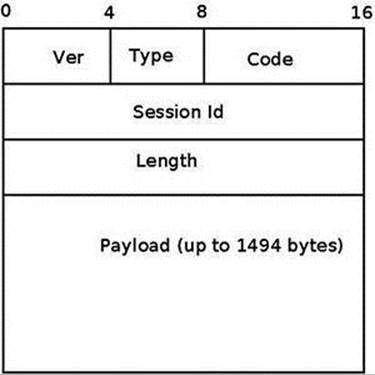
Figure 14-9. PPPoE header
PPPoE Initialization
PPPoE Initialization is done by the pppoe_init() method, drivers/net/ppp/pppoe.c. Two PPPoE protocol handlers are registered, one for PPPoE discovery packets, and one for PPPoE session packets. Let’s take a look at the PPPoE protocol handler registration:
static struct packet_type pppoes_ptype __read_mostly = {
.type = cpu_to_be16(ETH_P_PPP_SES),
.func = pppoe_rcv,
};
static struct packet_type pppoed_ptype __read_mostly = {
.type = cpu_to_be16(ETH_P_PPP_DISC),
.func = pppoe_disc_rcv,
};
static int __init pppoe_init(void)
{
int err;
dev_add_pack(&pppoes_ptype);
dev_add_pack(&pppoed_ptype);
. . .
return 0;
}
The dev_add_pack() method is the generic method for registering protocol handlers, and you encountered in previous chapters. The protocol handlers which are registered by the pppoe_init() method are:
· The pppoe_disc_rcv() method is the handler for PPPoE discovery packets.
· The pppoe_rcv() method is the handler for PPPoE session packets.
The PPPoE module exports an entry to procfs, /proc/net/pppoe. This entry consists of the session id, the MAC address, and the device of the current PPPoE sessions. Running cat /proc/net/pppoe is handled by the pppoe_seq_show() method. A notifier chain is registered by the pppoe_init() method by calling the register_netdevice_notifier(&pppoe_notifier).
PPPoX Sockets
PPPoX sockets are represented by the pppox_sock structure (include/linux/if_pppox.h) and are implemented in net/ppp/pppox.c. These sockets implement a Generic PPP encapsulation socket family. Apart from PPPoE, they are used also by Layer 2 Tunneling Protocol (L2TP) over PPP. PPPoX sockets are registered by calling register_pppox_proto(PX_PROTO_OE, &pppoe_proto) in the pppoe_init() method. Let’s take a look at the definition of the pppox_sock structure:
struct pppox_sock {
/* struct sock must be the first member of pppox_sock */
struct sock sk;
struct ppp_channel chan;
struct pppox_sock *next; /* for hash table */
union {
struct pppoe_opt pppoe;
struct pptp_opt pptp;
} proto;
__be16 num;
};
(include/linux/if_pppox.h)
When the PPPoX socket is used by PPPoE, the pppoe_opt of the proto union of the pppox_sock object is used. The pppoe_opt structure includes a member called pa, which is an instance of the pppoe_addr structure. The pppoe_addr structure represents the parameters of the PPPoE session: session id, remote MAC address of the peer, and the name of the network device that is used:
struct pppoe_addr {
sid_t sid; /* Session identifier */
unsigned char remote[ETH_ALEN]; /* Remote address */
char dev[IFNAMSIZ]; /* Local device to use */
};
(include/uapi/linux/if_pppox.h)
![]() Note Access to the pa member of the pppoe_opt structure which is embedded in the proto union is done in most cases in the PPPoE module using the pppoe_pa macro:
Note Access to the pa member of the pppoe_opt structure which is embedded in the proto union is done in most cases in the PPPoE module using the pppoe_pa macro:
#define pppoe_pa proto.pppoe.pa
(include/linux/if_pppox.h)
Sending and Receiving Packets with PPPoE
Once the discovery stage is completed, the PPP protocol must be used in order to enable traffic between the two peers, as was mentioned earlier. When starting a PPP connection by running, for example, pppd eth0 (see the example later in this section), the userspace pppd daemon creates a PPPoE socket by calling socket(AF_PPPOX, SOCK_STREAM, PX_PROTO_OE); this is done in the rp-pppoe plugin of the pppd daemon, in the PPPOEConnectDevice() method of pppd/plugins/rp-pppoe/plugin.c. This socket() system call creates a PPPoE socket by the pppoe_create() method of the PPPoE kernel module. Releasing the socket after the PPPoE session completed is done by the pppoe_release() method of the PPPoE kernel module. Let’s take a look at the pppoe_create() method:
static const struct proto_ops pppoe_ops = {
.family = AF_PPPOX,
.owner = THIS_MODULE,
.release = pppoe_release,
.bind = sock_no_bind,
.connect = pppoe_connect,
. . .
.sendmsg = pppoe_sendmsg,
.recvmsg = pppoe_recvmsg,
. . .
.ioctl = pppox_ioctl,
};
static int pppoe_create(struct net *net, struct socket *sock)
{
struct sock *sk;
sk = sk_alloc(net, PF_PPPOX, GFP_KERNEL, &pppoe_sk_proto);
if (!sk)
return -ENOMEM;
sock_init_data(sock, sk);
sock->state = SS_UNCONNECTED;
sock->ops = &pppoe_ops;
sk->sk_backlog_rcv = pppoe_rcv_core;
sk->sk_state = PPPOX_NONE;
sk->sk_type = SOCK_STREAM;
sk->sk_family = PF_PPPOX;
sk->sk_protocol = PX_PROTO_OE;
return 0;
}
(drivers/net/ppp/pppoe.c)
By defining pppoe_ops we set callbacks for this socket. So calling from userspace the connect() system call on an AF_PPPOX socket will be handled by the pppoe_connect() method of the PPPoE module in the kernel. After creating a PPPoE socket, thePPPOEConnectDevice() method calls connect(). Let’s take a look at the pppoe_connect() method:
static int pppoe_connect(struct socket *sock, struct sockaddr *uservaddr,
int sockaddr_len, int flags)
{
struct sock *sk = sock->sk;
struct sockaddr_pppox *sp = (struct sockaddr_pppox *)uservaddr;
struct pppox_sock *po = pppox_sk(sk);
struct net_device *dev = NULL;
struct pppoe_net *pn;
struct net *net = NULL;
int error;
lock_sock(sk);
error = -EINVAL;
if (sp->sa_protocol != PX_PROTO_OE)
goto end;
/* Check for already bound sockets */
error = -EBUSY;
The stage_session() method returns true when the session id is not 0 (as mentioned earlier, the session id is 0 in the discovery stage only). In case the socket is connected and it is in the session stage, the socket is already bound, so we exit:
if ((sk->sk_state & PPPOX_CONNECTED) &&
stage_session(sp->sa_addr.pppoe.sid))
goto end;
Reaching here means that the socket is not connected (it’s sk_state is not PPPOX_CONNECTED) and we need to register a PPP channel:
. . .
/* Re-bind in session stage only */
if (stage_session(sp->sa_addr.pppoe.sid)) {
error = -ENODEV;
net = sock_net(sk);
dev = dev_get_by_name(net, sp->sa_addr.pppoe.dev);
if (!dev)
goto err_put;
po->pppoe_dev = dev;
po->pppoe_ifindex = dev->ifindex;
pn = pppoe_pernet(net);
The network device must be up:
if (!(dev->flags & IFF_UP)) {
goto err_put;
}
memcpy(&po->pppoe_pa,
&sp->sa_addr.pppoe,
sizeof(struct pppoe_addr));
write_lock_bh(&pn->hash_lock);
The __set_item() method inserts the pppox_sock object, po, into the PPPoE socket hashtable; the hash key is generated according to the session id and the remote peer MAC address by the hash_item() method. The remote peer MAC address is po->pppoe_pa.remote. If there is an entry in the hash table with the same session id and the same remote MAC address and the same ifindex of the network device, the __set_item() method will return an error of –EALREADY:
error = __set_item(pn, po);
write_unlock_bh(&pn->hash_lock);
if (error < 0)
goto err_put;
po->chan is a ppp_channel object, see earlier in the pppox_sock structure definition. Before registering it by the ppp_register_net_channel() method, some of its members should be initialized:
po->chan.hdrlen = (sizeof(struct pppoe_hdr) +
dev->hard_header_len);
po->chan.mtu = dev->mtu - sizeof(struct pppoe_hdr);
po->chan.private = sk;
po->chan.ops = &pppoe_chan_ops;
error = ppp_register_net_channel(dev_net(dev), &po->chan);
if (error) {
The delete_item() method deletes a pppox_sock object from the PPPoE socket hashtable.
delete_item(pn, po->pppoe_pa.sid,
po->pppoe_pa.remote, po->pppoe_ifindex);
goto err_put;
}
Set the socket state to be connected:
sk->sk_state = PPPOX_CONNECTED;
}
po->num = sp->sa_addr.pppoe.sid;
end:
release_sock(sk);
return error;
err_put:
if (po->pppoe_dev) {
dev_put(po->pppoe_dev);
po->pppoe_dev = NULL;
}
goto end;
}
By registration of a PPP channel we are allowed to use PPP services. We are able to process PPPoE session packets by calling the generic PPP method, ppp_input(), from the pppoe_rcv_core() method. Transmission of PPPoE session packets is done with the genericppp_start_xmit() method.
RP-PPPoE is an open source project which provides a PPPoE client and a PPPoE server for Linux: http://www.roaringpenguin.com/products/pppoe. A simple example of running a PPPoE server is:
pppoe-server -I p3p1 -R 192.168.3.101 -L 192.168.3.210 -N 200
The options that are used in this example are:
· -I: The interface name (p3p1)
· -L: Set local IP address (192.168.3.210)
· -R: Set the starting remote IP address (192.168.3.101)
· -N: Max number of concurrent PPPoE sessions (200 in this case)
For other options, see man 8 pppoe-server.
Clients on the same LAN can create a PPPoE connection to this server by a pppd daemon, using the rp-pppoe plugin.
Android popularity as a mobile Operating System for smartphones and tablets is growing steadily. I will conclude the book with a short section about Android, discussing briefly the Android development model and showing four examples about Android networking.
Android
In the recent years, the Android operating system proved to be a very reliable and successful mobile OS. The Android operating system is based on a Linux kernel, with changes by Google developers. Android runs on hundreds of types of mobile devices, which are mostly based on the ARM processor. (I should mention that there is a project of porting Android to Intel x86 processors, http://www.android-x86.org/). The first generation of Google TV devices is based on x86 processors by Intel, but the second generation of Google TV devices are based on ARM. Originally Android was developed by “Android Inc.”, a company that was founded in California in 2003 by Andy Rubin and others. Google bought this company in 2005. The Open Handset Alliance (OHA), a consortium of over 80 companies, announced Android in 2007. Android is an open source operating system, and its source code is released under the Apache License. Unlike Linux, most of the development is done by Google employees behind closed doors. As opposed to Linux, there is no public mailing list where developers are sending and discussing patches. One can, however, send patches to public Gerrit (see http://source.android.com/source/submit-patches.html). But it is up to Google only to decide whether or not they will be included in the Android tree.
Google developers had contributed a lot to the Linux kernel. You had learned earlier in this chapter that the cgroup subsystem was started by Google developers. I will mention also two Linux kernel networking patches, the Receive Packet Steering (RPS) patch, and the Receive flow steering (RFS) patch by Tom Herbert from Google (see http://lwn.net/Articles/362339/ and http://lwn.net/Articles/382428/), which were integrated into kernel 2.6.35. When working with multicore platforms, RPS and RFS let you steer packets according to the hash of the payload to a specific CPU. And there are a lot of other examples of contributions from Google to the Linux kernel, and it seems that also in the future you will encounter many important contributions to the Linux kernel from Google. One can find a lot of code from Android kernel in the staging tree of the Linux kernel. However, it is difficult to say whether the Android kernel will be merged fully into the Linux kernel; probably a very large part of it will find its way into the Linux kernel. For more information about Mainlining Android see this wiki:http://elinux.org/Android_Mainlining_Project. In the past there were many obstacles in the way, as Google implemented unique mechanisms, like wakelocks, alternative power management, its own IPC (called Binder), which is based on a Lightweight Remote Procedure Call (RPC), Android shared memory driver (Ashmem), Low Memory Killer and more. In fact, the Kernel community rejected the Google power management wakelocks patches in 2010. But since then, some of these features were merged and the situation changed. (See “Autosleep and Wake Locks,” https://lwn.net/Articles/479841/, and “The LPC Android microconference”, https://lwn.net/Articles/570406/). Linaro (www.linaro.org/) is a non-profit organization that was established in 2010 by leading big companies such as ARM, Freescale, IBM, Samsung, ST-Ericsson, and Texas Instruments (TI). Its engineering teams develop Linux ARM kernel and also optimizations for GCC toolchain. Linaro teams are doing an amazing job of coordinating and pushing/tweaking changes upstream. Delving into the details of Android kernel implementation and mainlining is beyond the scope of this book.
Android Networking
The main networking issue with Android is, however, not due to Linux kernel but to Android userspace. Android heavily relies on HAL even for networking, as well as for system framework. Originally (i.e., up to 4.2), there’s no Ethernet support at all at framework level. If drivers are compiled in the kernel, the TCP/IP stack still allows basic Ethernet connectivity for Android Debug Bridge (ADB) debugging, but that’s all. Starting with 4.0, Android-x86 project fork added an early implementation (badly designed but somehow working) of Ethernet at framework level. Starting with 4.2, official upstream sources support Ethernet, but there is no way to actually configure it (it detects Ethernet plug in/out, and if a DHCP server is there, it provides an IP address to the interface). Applications can actually make use of this interface through framework, but mostly no one does this. If you require real Ethernet support (i.e., being able to configure your interface, static/DHCP configure it, set proxy, ensure that all apps are using the interface, then a lot of hacks are still required (see www.slideshare.net/gxben/abs-2013-dive-into-android-networking-adding-ethernet-connectivity). In all cases, only one interface is being supported at a time (eth0 only, even if you have eth0 and eth1, so don’t expect to act as a router of any kind). I will show here four short examples of how Android networking differs from Linux kernel networking:
· Security privileges and networking: Android added a security feature (named “paranoid network”) to the Linux kernel, which restricts access to some networking features, depending on the group of the calling process. As opposed to the standard Linux kernel, where any application can open a socket and transmit/receive with it, in Android access to network resources is filtered by GID (group ID). The part of network security will be probably very difficult to merge into the mainline kernel, as it includes many features that are unique to Android. For more information about Android network security, see http://elinux.org/Android_Security#Paranoid_network-ing.
· Bluetooth: Bluedroid is a Bluetooth stack based on code that was developed by Broadcom. It replaced the BlueZ based stack in Android 4.2. Support for Bluetooth Low Energy (BLE, or Bluetooth LE) devices, also known as Bluetooth Smart and Smart Ready devices, was introduced in Android 4.3 (API Level 18), July 2013. Prior to this, Android Open Source Project (AOSP) did not have support for BLE devices, but there were some vendors who provided an API to BLE.
· Netfilter: There is an interesting project from Google that provides better network statistics on Android. This is implemented by xt_qtaguid, a netfilter module, which enables userspace applications to tag their sockets. This project required some changes in the Linux kernel netfilter subsystem. Patches of these changes were also sent to the Linux Kernel Mailing List (LKML); see http://lwn.net/Articles/517358/. For details, see “Android netfilter changes”http://www.linuxplumbersconf.org/2013/ocw/sessions/1491.
· NFC: As was described in the Near Field Communication (NFC) section earlier in this chapter, the Android NFC architecture is a userspace NFC stack: the implementation is done in userspace through the HAL which is supplied by Broadcom or by Android OEMs.
Android internals: Resources
Although there are many resources about developing applications for Android (whether in books, mailing list, forums, courses, etc.), there are very few resources about the internals of Android. For those readers who are interested to learn more, I suggest these resources:
· The book Embedded Android: Porting, Extending, and Customizing, by Karim Yaghmour (O’Reilly Media, 2013)
· Slides: Android System Development by Maxime Ripard, Alexandre Belloni (over 400 slides); http://free-electrons.com/doc/training/android/.
· Slides: Android Platform Anatomy by Benjamin Zores (59 slides); http://www.slideshare.net/gxben/droidcon-2013-france-android-platform-anatomy.
· Slides: Jelly Bean Device Porting by Benjamin Zores (127 slides); http://www.slideshare.net/gxben/as-2013-jelly-bean-device-porting-walkthrough.
· Website: http://developer.android.com/index.html.
· Android platform internals forum - archives: http://news.gmane.org/gmane.comp.handhelds.android.platform
· Once a year, an Android Builders Summit (ABS) is held. The first ABS was held in 2011 in San Francisco. It is recommended to read slides, watch videos, or attend.
· XDA Developers Conference: http://xda-devcon.com/; Slides and videos in http://xda-devcon.com/presentations/
· Slides: Android Internals, Marko Gargenta: http://www.scandevconf.se/db/Marakana-Android-Internals.pdf
![]() Note Android git repositories are available in https://android.googlesource.com/
Note Android git repositories are available in https://android.googlesource.com/
Note that Android uses a special tool based on python called repo for management of hundreds of git repositories, which makes working with git easier.
Summary
I have dealt in this chapter with namespaces in Linux, focusing on network namespaces. I also described the cgroups subsystem and its implementation; furthermore, I described its two network modules, net_prio and cls_cgroup. The Linux Bluetooth subsystem and its implementation, the IEEE 802.15.4 Linux subsystem and 6LoWPAN, and the NFC subsystem were all covered. The optimization achieved by Low Latency Sockets Poll was also discussed in this chapter, along with the Notification Chains mechanism, which is widely used in the kernel networking stack (and you will encounter it when browsing the source code). Another topic that was briefly discussed was the PCI subsystem, in order to give some background about PCI devices, as many network devices are PCI devices. The chapter was concluded with three short sections about the network teaming driver (which is intended to replace the bonding driver), the PPPoE implementation, and Android.
Although we’ve come to the end of the book, there is much more to learn about Linux Kernel networking, as it is a vast ocean of details, and it is progressing dynamically and at such a fast pace. New features and new patches are added constantly. I hope you enjoyed the book and that you learned a thing or two!
Quick Reference
I will conclude with a list of methods and macros that were mentioned in this chapter.
Methods
The following list contains the prototypes and descriptions of several methods covered in this chapter.
void switch_task_namespaces(struct task_struct *p, struct nsproxy *new);
This method assigns the specified nsproxy object to the specified process descriptor (task_struct object).
struct nsproxy *create_nsproxy(void);
This method allocates an nsproxy object and initializes its reference counter to 1.
void free_nsproxy(struct nsproxy *ns);
This method released the resources of the specified nsproxy object.
struct net *dev_net(const struct net_device *dev);
This method returns the network namespace object (nd_net) associated with the specified network device.
void dev_net_set(struct net_device *dev, struct net *net);
This method associates the specified network namespace to the specified network device by setting the nd_net member of the net_device object.
void sock_net_set(struct sock *sk, struct net *net);
This method associates the specified network namespace to the specified sock object.
struct net *sock_net(const struct sock *sk);
This method returns the network namespace object (sk_net) associated with the specified sock object.
int net_eq(const struct net *net1, const struct net *net2);
This method returns 1 if the first specified network namespace pointer equals the second specified network namespace pointer and 0 otherwise.
struct net *net_alloc(void);
This method allocates a network namespace. It is invoked from the copy_net_ns() method.
struct net *copy_net_ns(unsigned long flags, struct user_namespace *user_ns, struct net *old_net);
This method creates a new network namespace if the CLONE_NEWNET flag is set in its first parameter, flags. It creates the new network namespace by first calling the net_alloc() method to allocate it, then it initializes it by calling the setup_net() method, and finally adds it to the global list of all namespaces, net_namespace_list. In case the CLONE_NEWNET flag is set in its first parameter, flags, there is no need to create a new namespace and the specified old network namespace, old_net, is returned. Note that this description of thecopy_net_ns() method refers to the case when CONFIG_NET_NS is set. When CONFIG_NET_NS is not set, there is a second implementation of copy_net_ns(), which the only thing it does is first verify that CLONE_NEWNET is set in the specified flags, and in case it is, returns the specified old network namespace (old_net); see include/net/net_namespace.h.
int setup_net(struct net *net, struct user_namespace *user_ns);
This method initializes the specified network namespace object. It assigns the network namespace user_ns member to be the specified user_ns, it initializes the reference counter (count) of the specified network namespace to be 1, and performs more initializations. It is invoked from the copy_net_ns() method and from the net_ns_init() method.
int proc_alloc_inum(unsigned int *inum);
This method allocates a proc inode and sets *inum to be the generated proc inode number (an integer between 0xf0000000 and 0xffffffff). It returns 0 on success.
struct nsproxy *task_nsproxy(struct task_struct *tsk);
This method returns the nsproxy object which is attached to the specified process descriptor (tsk).
struct new_utsname *utsname(void);
This method returns the new_utsname object which is associated with the process which currently runs (current).
struct uts_namespace *clone_uts_ns(struct user_namespace *user_ns, struct uts_namespace *old_ns);
This method creates a new UTS namespace object by calling the create_uts_ns() method, and copies the new_utsname object of the specified old_ns UTS namespace into the new_utsname of the newly created UTS namespace.
struct uts_namespace *copy_utsname(unsigned long flags, struct user_namespace *user_ns, struct uts_namespace *old_ns);
This method creates a new UTS namespace if the CLONE_NEWUTS flag is set in its first parameter, flags. It creates the new UTS namespace by calling the clone_uts_ns() method, and returns the newly created UTS namespace. In case the CLONE_NEWUTS flag is set in its first parameter, there is no need to create a new namespace and the specified old UTS namespace (old_ns) is returned.
struct net *sock_net(const struct sock *sk);
This method returns the network namespace object (sk_net) associated with the specified sock object.
void sock_net_set(struct sock *sk, struct net *net);
This method assigns the specified network namespace to the specified sock object.
int dev_change_net_namespace(struct net_device *dev, struct net *net, const char *pat);
This method changes the network namespace of the specified network device to be the specified network namespace. It returns 0 on success or –errno on failure. Callers must hold the rtnl semaphore. If the NETIF_F_NETNS_LOCAL flag is set in the features of the network device, an error of –EINVAL is returned.
void put_net(struct net *net);
This method decrements the reference counter of the specified network namespace. In case it reaches zero, it calls the __put_net() method to free its resources.
struct net *get_net(struct net *net);
This method returns the specified network namespace object after incrementing its reference counter.
void get_nsproxy(struct nsproxy *ns);
This method increments the reference counter of the specified nsproxy object.
struct net *get_net_ns_by_pid(pid_t pid);
This method gets a process id (PID) as an argument, and returns the network namespace object to which this process is attached.
struct net *get_net_ns_by_fd(int fd);
This method gets a file descriptor as an argument, and returns the network namespace associated with the inode that corresponds to the specified file descriptor.
struct pid_namespace *ns_of_pid(struct pid *pid);
This method returns the PID namespace in which the specified pid was created.
void put_nsproxy(struct nsproxy *ns);
This method decrements the reference counter of the specified nsproxy object; in case it reaches 0, the specified nsproxy is freed by calling the free_nsproxy() method.
int register_pernet_device(struct pernet_operations *ops);
This method registers a network namespace device.
void unregister_pernet_device(struct pernet_operations *ops);
This method unregisters a network namespace device.
int register_pernet_subsys(struct pernet_operations *ops);
This method registers a network namespace subsystem.
void unregister_pernet_subsys(struct pernet_operations *ops);
This method unregisters a network namespace subsystem.
static int register_vlan_device(struct net_device *real_dev, u16 vlan_id);
This method registers a VLAN device associated with the specified physical device (real_dev).
void cgroup_release_agent(struct work_struct *work);
This method is called when a cgroup is released. It creates a userspace process by invoking the call_usermodehelper() method.
int call_usermodehelper(char * path, char ** argv, char ** envp, int wait);
This method prepares and starts a userspace application.
int bacmp(bdaddr_t *ba1, bdaddr_t *ba2);
This method compares two Bluetooth addresses. It returns 0 if they are equal.
void bacpy(bdaddr_t *dst, bdaddr_t *src);
This method copies the specified source Bluetooth address (src) to the specified destination Bluetooth address (dst).
int hci_send_frame(struct sk_buff *skb);
This method is the main Bluetooth method for transmitting SKBs (commands and data).
int hci_register_dev(struct hci_dev *hdev);
This method registers the specified HCI device. It is invoked from Bluetooth device drivers. If the open() or close() callbacks of the specified hci_dev object are not defined, the method will fail and return –EINVAL. This method sets the HCI_SETUP flag in the dev_flagsmember of the specified HCI device; it also creates a sysfs entry for the device.
void hci_unregister_dev(struct hci_dev *hdev);
This method unregisters the specified HCI device. It is invoked from Bluetooth device drivers. It sets the HCI_UNREGISTER flag in the dev_flags member of the specified HCI device; it also removes the sysfs entry of the device.
void hci_event_packet(struct hci_dev *hdev, struct sk_buff *skb);
This method handles events that are received from the HCI layer by the hci_rx_work() method.
int lowpan_rcv(struct sk_buff *skb, struct net_device *dev, struct packet_type *pt, struct net_device *orig_dev);
This method is the main Rx handler for 6LoWPAN packets. 6LoWPAN packets have an ethertype of 0x00F6.
void pci_unregister_driver(struct pci_driver *dev);
This method unregisters a PCI driver. It is usually called in the network driver module_exit() method.
int pci_enable_device(struct pci_dev *dev);
This method initializes the PCI device before it is used by driver.
int request_irq(unsigned int irq, irq_handler_t handler, unsigned long flags, const char *name, void *dev);
This method registers the specified handler as the interrupt service routine for the specified irq.
void free_irq(unsigned int irq, void *dev_id);
This method frees an interrupt which was allocated with the request_irq() method.
int nfc_init(void);
This method performs initialization of the NFC subsystem by registering the generic netlink NFC family, initializing NFC Raw sockets and NFC LLCP sockets, and initializing the AF_NFC protocol.
int nfc_register_device(struct nfc_dev *dev);
This method registers an NFC device (an nfc_dev object) against the NFC core.
int nfc_hci_register_device(struct nfc_hci_dev *hdev);
This method registers an NFC HCI device (an nfc_hci_dev object) against the NFC HCI layer.
int nci_register_device(struct nci_dev *ndev);
This method registers an NFC NCI device (an nci_dev object) against the NFC NCI layer.
static int __init pppoe_init(void);
This method initializes the PPPoE layer (PPPoE protocol handlers, the sockets used by PPPoE, the network notification handler, the PPPoE procfs entry, and more).
struct pppoe_hdr *pppoe_hdr(const struct sk_buff *skb);
This method returns the PPPoE header associated with the specified skb.
static int pppoe_create(struct net *net, struct socket *sock);
This method creates a PPPoE socket. Return 0 on success or –ENOMEM if allocation of a socket by the sk_alloc() method failed.
int __set_item(struct pppoe_net *pn, struct pppox_sock *po);
This method inserts the specified pppox_sock object into the PPPoE socket hashtable. The hash key is calculated according to the session id and the remote peer MAC address by the hash_item() method.
void delete_item(struct pppoe_net *pn, __be16 sid, char *addr, int ifindex);
This method removes the PPPoE socket hashtable entry which has the specified session id, the specified MAC address, and the specified network interface index (ifindex).
bool stage_session(__be16 sid);
This method returns true when the specified session id is not 0.
int notifier_chain_register(struct notifier_block **nl, struct notifier_block *n);
This method registers the specified notifier_block object (n) to the specified notifier chain (nl). Note that this method is not used directly, there are several wrappers around it.
int notifier_chain_unregister(struct notifier_block **nl, struct notifier_block *n);
This method unregistered the specified notifier_block object (n) from the specified notifier chain (nl). Note that also this method is not used directly, there are several wrappers around it.
int register_netdevice_notifier(struct notifier_block *nb);
This method registers the specified notifier_block object to netdev_chain by calling the raw_notifier_chain_register() method.
int unregister_netdevice_notifier(struct notifier_block *nb);
This method unregisters the specified notifier_block object from netdev_chain by calling the raw_notifier_chain_unregister() method.
int register_inet6addr_notifier(struct notifier_block *nb);
This method registers the specified notifier_block object to inet6addr_chain by calling the atomic_notifier_chain_register() method.
int unregister_inet6addr_notifier(struct notifier_block *nb);
This method unregisters the specified notifier_block object from inet6addr_chain by calling the atomic_notifier_chain_unregister() method.
int register_netevent_notifier(struct notifier_block *nb);
This method registers the specified notifier_block object to netevent_notif_chain by calling the atomic_notifier_chain_register() method.
int unregister_netevent_notifier(struct notifier_block *nb);
This method unregisters the specified notifier_block object from netevent_notif_chain by calling the atomic_notifier_chain_unregister() method.
int __kprobes notifier_call_chain(struct notifier_block **nl, unsigned long val, void *v, int nr_to_call, int *nr_calls);
This method is for generating notification events. Note that also this method is not used directly, there are several wrappers around it.
int call_netdevice_notifiers(unsigned long val, struct net_device *dev);
This method is for generating notification events on the netdev_chain, by calling the raw_notifier_call_chain() method.
int blocking_notifier_call_chain(struct blocking_notifier_head *nh, unsigned long val, void *v);
This method is for generating notification events; eventually, after using locking mechanism, it invokes the notifier_call_chain() method.
int __atomic_notifier_call_chain(struct atomic_notifier_head *nh,unsigned long val, void *v, int nr_to_call, int *nr_calls);
This method is for generating notification events. Eventually, after using locking mechanism, it invokes the notifier_call_chain() method.
Macros
Here you’ll find a description of the macro that was covered in this chapter.
pci_register_driver()
This macro registers a PCI driver in the PCI subsystem. It gets a pci_driver object as a parameter. It is usually called in the network driver module_init() method.
All materials on the site are licensed Creative Commons Attribution-Sharealike 3.0 Unported CC BY-SA 3.0 & GNU Free Documentation License (GFDL)
If you are the copyright holder of any material contained on our site and intend to remove it, please contact our site administrator for approval.
© 2016-2026 All site design rights belong to S.Y.A.