RHCSA & RHCE Red Hat Enterprise Linux 7: Training and Exam Preparation Guide (EX200 and EX300), Third Edition (2015)
Part I. RHCSA Section
Chapter 12. Administering Network Interfaces and Network Clients
This chapter describes the following major topics:
· Basic networking including hostname, IPv4, IPv6, network classes, subnet, subnet mask, protocol, TCP/UDP, Ethernet addresses, and ARP
· Understand network interfaces and consistent interface naming
· Comprehend interface configuration files, hosts table, and management commands
· Overview of NetworkManager
· Configure a network interface manually and with NetworkManager
· Use ping to test connectivity
· Manage network interfaces via Graphical Network Administration tool
· Configure a system to get time from NTP servers
· OpenLDAP concepts, terminology, roles, and client packages
· Understand OpenLDAP client configuration files
· Configure OpenLDAP client with authconfig tool
· Overview of Graphical Authentication Configuration tool
RHCSA Objectives:
31. Configure networking and hostname resolution statically or dynamically
40. Configure a system to use time services
47. Configure a system to use an existing authentication service for user and group information
Acomputer network is a group of two or more physical or virtual computers connected together to share their resources and data. The computers may be interlinked via wired or wireless means, and a device such as a switch is required to interconnect several computers so that they can communicate with one another on the network.
To comprehend how networks work and how network services are configured properly, some basic networking terminology needs to be understood first. For a system to be able to talk to other networked systems, one of its network interfaces must be configured with a unique IP address, hostname, and other essential network parameters. Several files are involved for the interface configuration, which may be modified by hand or by using commands and graphical tools. After networking has been configured, testing is done to confirm the system’s ability to communicate with other systems on the network.
NTP is a networking protocol that allows a system to synchronize its clock with a more reliable source of time in order for time-sensitive applications running on the system to function accurately.
OpenLDAP is an open source implementation of LDAP. In order for a system to have its users authenticated by a remote OpenLDAP server and to obtain other directory information, the OpenLDAP client functionality needs to be configured on the system. There are certain configuration files that are modified for this purpose, and they may be edited manually, or via commands and graphical tools.
Basic Networking
There are many basic concepts and terms that you need to grasp before being able to configure network interfaces and perform advanced network client and server setups. Likewise, there are also many configuration files and commands related to various network services that you need to thoroughly understand. Some of the concepts, terms, configuration files, and commands are explained in this chapter, and many more will be introduced in the RHCE section of this book.
Hostname
A hostname is a unique alphanumeric label (the dash, underscore, and dot characters are also allowed) that is assigned to a system to identify it on the network. It can consists of up to 64 characters. It is normally allotted based on the purpose and primary use of the system. In RHEL7, the hostname is stored in the /etc/hostname file.
The hostname of a system can be viewed with the use of several different commands, such as hostname, hostnamectl, and uname. We can also display the contents of the /etc/hostname file where the hostname is stored. Moreover, the NetworkManager service is also available to show us the hostname at the command prompt, in text mode, and in graphical mode.
# hostname
server1.example.com
# hostnamectl | grep hostname
Static hostname: server1.example.com
# uname –n
server1
# cat /etc/hostname
server1.example.com
# nmcli general hostname
server1.example.com
Similarly, the hostname can be changed using any of the methods mentioned above, except for the uname command. The hostname command allows you to rename the hostname temporarily. For instance, to rename server1.example.com to server10.example.com, run this command as follows:
# hostname server10.example.com
The hostnamectl command changes the hostname on a permanent basis. The following renames server10.example.com to server100.example.com:
# hostnamectl set-hostname server100.example.com
Alternatively, you can simply edit the /etc/hostname file and make the desired change in it. After saving the file and exiting the editor, restart the systemd-hostnamed service for this permanent change to take effect right away. The following changes the hostname back to server1.example.com:
# vi /etc/hostname
server1.example.com
# systemctl restart systemd-hostnamed
Do not forget to update the /etc/hosts file to reflect the new hostname.
The NetworkManager can also be used to change the hostname via its command line interface (nmcli) or text interface (nmtui).
IPv4 Address
IPv4 stands for Internet Protocol version 4 and it represents a unique 32-bit software address that every single system on the network must have in order to communicate with other systems. It was the first version of IP that was released for public use. IPv4 addresses can be assigned on a temporary or permanent basis. Temporary addresses are referred to as dynamic addresses and are typically leased from a DHCP server for a specific period of time. Permanent addresses, on the other hand, are called static addresses and are set either manually or using the NetworkManager service. Permanent addresses are typically not changed unless there is a need.
We use the ip command with the addr argument to view current IP assignments on our system:
# ip addr
1: lo: <LOOPBACK,UP,LOWER_UP> mtu 65536 qdisc noqueue state UNKNOWN
link/loopback 00:00:00:00:00:00 brd 00:00:00:00:00:00
inet 127.0.0.1/8 scope host lo
valid_lft forever preferred_lft forever
inet6 ::1/128 scope host
valid_lft forever preferred_lft forever
2: eth0: <BROADCAST,MULTICAST,UP,LOWER_UP> mtu 1500 qdisc pfifo_fast state UP qlen 1000
link/ether 52:54:00:17:91:8d brd ff:ff:ff:ff:ff:ff
inet 192.168.0.110/24 brd 192.168.0.255 scope global eth0
valid_lft forever preferred_lft forever
inet6 fe80::5054:ff:fe17:918d/64 scope link
valid_lft forever preferred_lft forever
![]() We can also use the ifconfig command to obtain this information, but this command is deprecated in RHEL7 and will be removed from a future RHEL release.
We can also use the ifconfig command to obtain this information, but this command is deprecated in RHEL7 and will be removed from a future RHEL release.
The above output indicates the presence of one configured network interface called eth0 on the system with IPv4 address 192.168.0.110 assigned to it. The other interface, called lo, is a special purpose software interface reserved for use on every UNIX and Linux system. Its IPv4 address is always 127.0.0.1 and it is referred to as the system’s loopback (or localhost) address. This hostname is used by network applications to access the networking resources on the local system.
Network Classes
An IP address is comprised of four dot-separated octets that are divided into a network portion and a node portion. The network portion identifies the correct destination network and the node portion identifies the correct destination node on that network. Network addresses are classified into three classes, referred to as class A, class B, and class C. Classes D and E are also defined and in use; however, their use is limited to special areas such as scientific and engineering.
![]() A node is any device on the network with an IP address. Examples include computers, storage devices, routers, switches, hand-held devices, printers, and so on.
A node is any device on the network with an IP address. Examples include computers, storage devices, routers, switches, hand-held devices, printers, and so on.
Class A addresses are used for large networks with up to 16 million nodes. The network address range for class A networks is between 1 and 126. This class uses the first octet as the network portion and the rest of the octets as the node portion.
Class B addresses are used for mid-sized networks with up to 65 thousand nodes. The network address range for class B networks is between 128 and 191. This class uses the first two octets as the network portion and the other two octets as the node portion.
Class C addresses are used for small networks with up to 254 nodes. The network address range for class C networks is between 192 and 223. This class uses the first three octets as the network portion and the last octet as the node portion.
Subnetting and Subnet Mask
Subnetting is a method by which a large network address space can be divided into several smaller and more manageable logical sub-networks, commonly referred to as subnets. Subnetting usually results in reduced network traffic, improved network performance, and de-centralized and easier administration, among other benefits.
The following should be kept in mind when dealing with subnetting:
· Subnetting does not increase the number of IP addresses in a network. In fact, it reduces the number of usable IP addresses.
· All nodes in a given subnet have the same subnet mask.
· Each subnet acts as an isolated network and requires a router to talk to other subnets.
· The first and the last IP address in a subnet are reserved. The first address points to the subnet itself and the last address is the broadcast address.
After a given address has been subnetted, we determine something called subnet mask or netmask. The subnet mask is the network portion plus the subnet bits. In other words, the subnet mask segregates the network bits from the node bits. It is used by routers to identify the start and end of the network/subnet portion and the start and end of the node portion for a given IP address.
The default subnet masks for class A, B, and C networks are 255.0.0.0, 255.255.0.0, and 255.255.255.0, respectively.
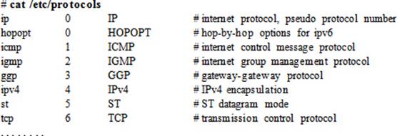
Protocol
A protocol is a set of rules governing the exchange of data between two networked entities. These rules include how data is formatted, coded, and controlled. The rules also provide error handling, speed matching, and data packet sequencing. In other words, a protocol is a common language that all nodes on the network speak and understand. Some common protocols are TCP, UDP, IP, and ICMP. Protocols are defined in the /etc/protocols file. An excerpt from this file is provided below:
TCP and UDP Protocols
Two key protocols besides IP are TCP and UDP. TCP is reliable, connection-oriented, and point-to-point. When a stream of packets is sent to the destination node using the TCP protocol, the destination node checks for errors and packet sequencing upon its arrival. Each packet contains information such as the IP addresses for the source and destination systems, port numbers, data, a sequence number, and checksum fields. The TCP protocol at the source node establishes a point-to-point connection with the peer TCP protocol at the destination. When the packet is received by the receiving TCP, an acknowledgment is returned. If the packet contains an error or is lost in transit, the destination node requests the source node to resend the packet. This ensures guaranteed data delivery and makes TCP reliable.
UDP, on the other hand, is unreliable, connectionless, and multi-point. If a packet is lost or contains errors upon arrival at the destination, the source node is unaware of it. The destination node does not send an acknowledgment back to the source node. UDP is normally used for broadcast purposes.
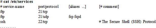
Both TCP and UDP protocols use ports for data transmission between a client and its associated server program. Ports are defined in the /etc/services file. Some common services and the ports they listen on are: ftp 21, ssh 22, postfix 25, http 80, and ntp 123. An excerpt from the /etc/services file is shown below:
Ethernet Address and Address Resolution Protocol
An Ethernet address represents a unique 48-bit address that is used to identify the correct destination node for data packets transmitted from the source node. The data packets include Ethernet addresses for both the source and the destination node. A network protocol called ARP, maps the Ethernet address to the destination node’s IP address. The Ethernet address is also referred to as the hardware, physical, link layer, or MAC address.
We can use the ip command to list all network interfaces available on the system along with their hardware addresses:
# ip addr | grep ether
link/ether 52:54:00:17:91:8d brd ff:ff:ff:ff:ff:ff
IP and Ethernet addresses work hand in hand, and a combination of both is critical to identifying the correct destination node on the network. A protocol called Address Resolution Protocol (ARP) is used to enable IP and hardware addresses to work together. ARP determines the hardware address of the destination node when its IP address is already known.
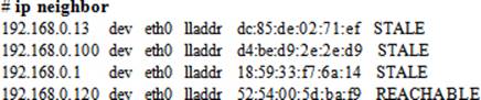
ARP broadcasts messages over the network requesting each alive neighbor to reply with its link layer and IP addresses. The addresses received are cached locally on the node, and can be viewed using the ip command with the neighbor argument:
![]() We can also use the arp command to obtain this information, but this command is now obsolete.
We can also use the arp command to obtain this information, but this command is now obsolete.
The above output shows IP addresses of the neighbors in the first column followed by the interface devices that they are using, their link layer addresses, and their NUD (Nieghbor Unreachability Detection) states. A neighbor can be in one of four states: permanent, noarp, reachable, and stale. The permanent state indicates a valid entry that can only be deleted manually, the noarp state designates a valid entry that expires at the end of its lifetime, the reachable state shows a valid entry that expires when its reachability timeout expires, and the stale state specifies a valid but suspicious entry.
Network Interfaces
Network Interface Cards are the hardware adapters that provide one or more Ethernet ports for network connectivity, and they are abbreviated as NICs. NICs may also be referred to as network adapters and individual ports as network interfaces or simply interfaces. NICs may be built-in to the system board or are add-on adapters. They are available in one to four port configuration on a single adapter. Two or more interfaces can be configured to provide bonding and teaming for redundancy and faster throughput. Individual interfaces as well as bonding and teaming can be configured with IPv4 and IPv6 assignments by editing files, or using either commands or the NetworkManager toolset. Additional tasks such as activating and deactivating them manually and auto-activating them at system reboots can also be performed with these tools. We discuss interface configuration and their administration in this chapter; bonding and teaming are RHCE topics and are covered in Chapter 15 “Configuring Bonding, Teaming, IPv6, and Routing”.
Consistent Interface Naming
In earlier RHEL versions, network interfaces were named eth (Ethernet), em (embedded), and wlan (wireless lan) and were numbered beginning at 0 as the interfaces were discovered during a system boot. This was the default interface naming scheme that had been in place for years. Given a large number of interfaces located onboard and on add-on NIC adapters, these number assignments could possibly change on the next boot, resulting in all kinds of connectivity and system operational issues. As of RHEL7, the default naming scheme is now based on several rules governed by systemd and udevd, which assign names based on BIOS/topology/location information. The key rules are presented below for Ethernet interfaces and are applied in the order in which they are listed. These rules are applicable to wireless adapters as well.
1. Onboard interfaces at firmware/BIOS-supplied index numbers (e.g. eno1).
2. Interfaces at PCI Express hotplug slot numbers (e.g. ens3).
3. Adapters in the specified PCI slot, with slot index number on the adapter (e.g. enp3s0).
4. If the above rules are disabled or the information furnished by firmware/BIOS is invalid, the system reverts to the traditional ethX convention.
This advanced ruleset has resulted in consistent naming, eliminating the odds of re-enumeration during a hardware rescan. Moreover, the assigned names are not affected by the addition or removal of interface cards. This naming scheme helps in identifying, configuring, troubleshooting, and replacing the right adapter without hassle.
In order to apply the above naming, we need to ensure that the biosdevname software package is removed from the system and no custom udev rules are in place for interface naming.
Understanding Interface Configuration File
Each network interface has a configuration file that stores IP assignments and other relevant parameters for the interface. The system reads this file and applies the settings at the time the interface is activated. Configuration files for all interfaces are stored at a central location, which is the/etc/sysconfig/network-scripts directory. The interface file names begin with ifcfg- and is followed by the name of the interface by which the system recognizes it. Some instances of interface file names are ifcfg-eth0, ifcfg-enp0s3, ifcfg-br0, and ifcfg-em1.
On server1 and server2, we used eth0 for the interface that we had configured at the time of installation as we picked up the virtual bridge br0 for the default interface. If we had chosen ‘default NAT’, the interface name would have been ens3 as the default.
The current contents of the ifcfg-eth0 file from server1 are presented below:
# cat /etc/sysconfig/network-scripts/ifcfg-eth0
DEVICE="eth0"
ONBOOT=yes
NETBOOT=yes
UUID="0764d665-dd86-4001-bdc5-3b280d32a11d"
IPV6INIT=yes
BOOTPROTO=none
TYPE=Ethernet
NAME="eth0"
HWADDR=52:54:00:17:91:8D
IPADDR0=192.168.0.110
PREFIX0=24
GATEWAY0=192.168.0.1
DEFROUTE=yes
IPV4_FAILURE_FATAL=no
IPV6_AUTOCONF=yes
IPV6_DEFROUTE=yes
IPV6_FAILURE_FATAL=no
IPV6_PEERDNS=yes
IPV6_PEERROUTES=yes
These and a few other directives that can be defined in this file are described in Table 12-1.
|
Directive |
Description |
|
BOOTPROTO |
Defines the boot protocol to be used. Values include “dhcp” to obtain IP from a DHCP server, “bootp” to boot off of a network boot server and get IP, and “none” or “static” to use a static IP set with the IPADDR directive. |
|
BRIDGE |
Specifies the name of the network bridge to be used. On host1, we created br0 in Chapter 06 “Configuring Server Virtualization and Network Installing RHEL7”. |
|
BROADCAST0 |
Sets the broadcast IP address for the first IP on this interface. |
|
DEFROUTE |
Whether to use this interface as the default route. |
|
DEVICE |
Specifies the device name for the network interface. |
|
DNS1 |
Places an entry for the first DNS server in the /etc/resolv.conf file if PEERDNS directive is set to “yes” in this file. |
|
GATEWAY0 |
Specifies the gateway address for the first IP on this interface. |
|
HWADDR |
Describes the hardware address for this interface. |
|
IPADDR0 |
Specifies the IP for this interface. |
|
IPV6INIT |
Whether to enable IPv6 support for this interface. |
|
NAME |
Any description given to this interface. |
|
NETMASK0 |
Sets the netmask address for the first IP on this interface. |
|
NM_CONTROLLED |
Whether the NetworkManager service is allowed to modify the configuration in this file. Default is yes. |
|
ONBOOT |
Whether to activate this interface at system boot. |
|
PEERDNS |
Whether to modify the DNS client resolver file /etc/resolv.conf. Default is “yes” if BOOTPROTO=dhcp is set. |
|
USERCTL |
Whether to allow non-root users to activate this interface. |
|
UUID |
The UUID associated with this interface. |
|
TYPE |
Specifies the type of this interface. |
Table 12-1 Network Interface Configuration File
Understanding the Hosts Table
Each IP configured on an interface has a hostname assigned to it. In an environment with multiple networked systems, it is prudent to have some kind of hostname to IP resolution in place to avoid typing the destination system IP over and over when we need to access it. DNS is one such method. It is designed for large networks such as corporate networks and the Internet. For small, internal networks, the use of a local host table (the /etc/hosts file) is more common. This table is used to maintain hostname to IP mapping for all systems on the local network, allowing us access to a system by simply typing its hostname. From the standpoint of this book, we have three systems in place: host1.example.com with IP 192.168.0.100 and alias host1; server1.example.com with IP 192.168.0.110 and alias server1; and server2.example.com with IP 192.168.0.120 and alias server2. We can append this IP and hostname information to the /etc/hosts file as shown below:
|
192.168.0.100 |
host1.example.com |
host1 |
|
192.168.0.110 |
server1.example.com |
server1 |
|
192.168.0.120 |
server2.example.com |
server2 |
Each row in the file contains an IP address in the first column followed by the official (or canonical) hostname in the second column, and one or more aliases subsequently. The official hostname and one or more aliases give us the flexibility of accessing a system using any of these names.
EXAM TIP: In the presence of an active DNS with all hostnames resolvable, there is no need to worry about updating the hosts file.
As indicated above, the hosts file is normally used on small networks only, and therefore must be updated on each individual system to reflect changes.
Interface Administration Commands
There are several commands available to administer network interfaces. The NetworkManager service includes a toolset for this purpose as well, which provides us with access to a command line interface and a text interface. Table 12-2 lists and describes the commands and the NetworkManager tools.
|
Command |
Description |
|
ifdown / ifup |
Deactivates / activates an interface. |
|
ip |
A powerful tool for administering interfaces, routing, etc. It is a replacement for ifconfig and netstat obsoleted commands. |
|
nm-connection-editor |
A graphical tool for interface administration. |
|
Network Settings |
A graphical connection status and network administration tool. |
|
NetworkManager Tools |
|
|
nmcli |
A command line tool for interface administration. |
|
nmtui |
A text-based tool for interface administration. |
Table 12-2 Network Interface Administration Tools
What is NetworkManager?
NetworkManager is the default interface configuration and monitoring service available in RHEL7. It has a daemon program called NetworkManager that dynamically keeps configured interfaces up and active. It has a set of client programs for managing network interfaces and controlling the service itself from the command line (nmcli) or via the text tool (nmtui). The availability of these tools is dependent on the presence of NetworkManager and NetworkManager-tui software packages on the system. By default, the NetworkManager service is enabled and active.
The nmcli utility is powerful and has many options available for effective interface administration. Its text equivalent is nmtui, which also allows us to add, modify, and delete an interface connection, activate and deactivate an interface, and change the hostname of the system. The main window, as depicted in Figure 12-1, appears when we issue nmtui at the command prompt:
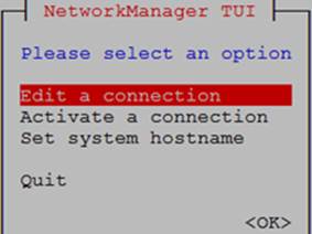
Figure 12-1 NetworkManager TUI
This tool updates appropriate files on the system for any operations that we perform.
Exercise 12-1: Present, Configure, and Activate a Network Interface Manually
This exercise should be done on host1 and server1.
In this exercise, you will add a new network interface to the virtual machine hosting server1, with the source device “Host device em1 (Bridge ‘br0’)”, default MAC address, and device model virtio. On server1, you will call this interface eth1 and manually assign the IP 192.168.0.111/24 for temporary use. You will copy the ifcfg-eth0 file in the /etc/sysconfig/network-scripts directory as ifcfg-eth1 and modify it. You will set this interface to autoactivate at system reboots. You will deactivate and reactivate this interface at the command prompt. You will reboot server1 and verify the persistence of IP assignments for this new interface. You will assign it hostname server1ipv4.example.com and alias server1ipv4 and update the hosts file accordingly.
1. Open the virtual console for server1 on host1. Click “Show virtual hardware details” | Add Hardware | Network. Select host device “Host device em1 (Bridge ‘br0’)” from the drop-down list and device model virtio. Leave the MAC address to the default. Click Finish to complete the new interface assignment.
2. Log on to server1 as root and run the ip command to look for the new interface:
# ip addr
…… . .
3: eth1: <BROADCAST,MULTICAST,UP,LOWER_UP> mtu 1500 qdisc pfifo_fast state UP qlen 1000
link/ether 52:54:00:39:16:9a brd ff:ff:ff:ff:ff:ff
The output indicates the presence of a new interface by the name eth1.
3. Assign IP 192.168.0.111/24 to eth1:
# ip addr add 192.168.0.111/24 broadcast 192.168.0.255 dev eth1
4. Verify the new IP assignments on eth1:
# ip addr
3: eth1: <BROADCAST,MULTICAST,UP,LOWER_UP> mtu 1500 qdisc pfifo_fast state UP qlen 1000
link/ether 52:54:00:39:16:9a brd ff:ff:ff:ff:ff:ff
inet 192.168.0.111/24 brd 192.168.0.255 scope global eth1
valid_lft forever preferred_lft forever
At this point, if you reboot server1, this IP information will be lost. You need to configure the settings in a file for persistence.
5. Copy the ifcfg-eth0 file as ifcfg-eth1 in the /etc/sysconfig/network-scripts directory:
# cd /etc/sysconfig/network-scripts
# cp ifcfg-eth0 ifcfg-eth1
6. Open ifcfg-eth1 in a text editor and modify the contents accordingly. On my server1, it will look as shown below:
# vi ifcfg-eth1
DEVICE="eth1"
ONBOOT=yes
NETBOOT=yes
IPV6INIT=yes
BOOTPROTO=none
TYPE=Ethernet
NAME="eth1"
IPADDR0=192.168.0.111
PREFIX0=24
GATEWAY0=192.168.0.1
DEFROUTE=yes
IPV4_FAILURE_FATAL=no
IPV6_AUTOCONF=yes
IPV6_DEFROUTE=yes
IPV6_FAILURE_FATAL=no
HWADDR=52:54:00:39:16:9A
IPV6_PEERDNS=yes
IPV6_PEERROUTES=yes
7. Deactivate this interface and then reactivate using the ifdown and ifup commands:
# ifdown eth1
# ifup eth1
Connection successfully activated (D-Bus active path: /org/freedesktop/NetworkManager/ActiveConnection/2)
8. Reboot the system:
# reboot
9. Verify the presence of eth1 assignments:
# ip addr
3: eth1: <BROADCAST,MULTICAST,UP,LOWER_UP> mtu 1500 qdisc pfifo_fast state UP qlen 1000
link/ether 52:54:00:39:16:9a brd ff:ff:ff:ff:ff:ff
inet 192.168.0.111/24 brd 192.168.0.255 scope global eth1
valid_lft forever preferred_lft forever
10. Open the hosts file and append the following entry to it:
# vi /etc/hosts
192.168.0.111 server1ipv4.example.com server1ipv4
You can use puTTY in Windows and attempt to access the server using this new IP.
The nmcli Command
The nmcli command is a NetworkManager service tool, which allows us to create, view, modify, remove, activate, and deactivate network interfaces, and control and report their status. This tool operates on one of five objects at a time, with each object supporting several options to form a complete command. The five objects are general, networking, radio, connection, and device. For our purposes, the objects connection and device are important, and are described in Table 12-3.
|
Object |
Description |
|
Connection: activates, deactivates, and administers network connections. |
|
|
show |
Lists connection profiles. |
|
up / down |
Activates/deactivates a connection. |
|
add |
Adds a connection. |
|
edit |
Edits an existing connection or adds a new one. |
|
modify |
Modifies one or more properties in the connection profile. |
|
delete |
Deletes a connection. |
|
reload |
Instructs NetworkManager to re-read all interface configuration files. |
|
load |
Instructs NetworkManager to re-read the specified interface configuration file. |
|
Device: displays and administers network interfaces. |
|
|
status |
Displays device status. |
|
show |
Displays detailed information about all or the specified interface. |
Table 12-3 Network Interface Administration Tools
Objects may be abbreviated. For instance, the connection object may be specified as a ‘c’ or ‘con’. Similarly, the device object can be abbreviated as a ‘d’ or ‘dev’.
Exercise 12-2: Present, Configure, and Activate a Network Interface Using NetworkManager CLI
This exercise should be done on host1 and server2.
In this exercise, you will add a new network interface to the virtual machine hosting server2, with the source device “Host device em1 (Bridge ‘br0’)”, default MAC address, and device model virtio. On server2, you will call this interface eth1 and assign IP 192.168.0.121/24 using the NetworkManager CLI. You will deactivate and reactivate this interface at the command prompt. You will reboot server2 and verify the persistence of IP assignments for this new interface. You will assign it hostname server2-eth1.example.com and alias server2-eth1 and update the hosts file accordingly.
1. Open the virtual console for server2 on host1. Click “Show virtual hardware details” | Add Hardware | Network. Select host device “Host device em1 (Bridge ‘br0’)” from the drop-down list and device model virtio. Leave the MAC address to the default. Click Finish to complete the new interface assignment.
2. Log on to server2 and check the running status of NetworkManager service:
# systemctl status NetworkManager
NetworkManager.service - Network Manager
Loaded: loaded (/usr/lib/systemd/system/NetworkManager.service; enabled)
Active: active (running) since Mon 2014-11-17 11:00:52 EST; 28min ago
…… . .
3. Look for the new interface with the ip command:
# ip addr
…… . .
3: eth1: <BROADCAST,MULTICAST,UP,LOWER_UP> mtu 1500 qdisc pfifo_fast state UP qlen 1000
link/ether 52:54:00:96:13:58 brd ff:ff:ff:ff:ff:ff
The output indicates the presence of a new interface by the name eth1.
4. List all configured interfaces on the server:

5. Show the status of all available interfaces on the server:
6. Add a connection of type Ethernet, interface name eth1, connection name eth1, IP 192.168.0.121/24, and gateway 192.168.0.1:
# nmcli con add type Ethernet ifname eth1 con-name eth1 ip4 192.168.0.121/24 \ gw4 192.168.0.1
Connection 'eth1' (7f365451-fd33-44f0-bffb-45de70d06fe0) successfully added.
The nmcli command has added the new interface and has activated it. In addition, it has created the ifcfg-eth1 file in the /etc/sysconfig/network-scripts directory with all necessary directives.
7. Check the new connection and IP assignments:
# ip addr
…… . .
3: eth1: <BROADCAST,MULTICAST,UP,LOWER_UP> mtu 1500 qdisc pfifo_fast state UP qlen 1000
link/ether 52:54:00:96:13:58 brd ff:ff:ff:ff:ff:ff
inet 192.168.0.121/24 brd 192.168.0.255 scope global eth1
valid_lft forever preferred_lft forever
inet6 fe80::5054:ff:fe96:1358/64 scope link
valid_lft forever preferred_lft forever
8. Check the contents of the ifcfg-eth1 file:
# cat /etc/sysconfig/network-scripts/ifcfg-eth1
TYPE=Ethernet
BOOTPROTO=none
IPADDR0=192.168.0.121
PREFIX0=24
GATEWAY0=192.168.0.1
DEFROUTE=yes
IPV4_FAILURE_FATAL=no
IPV6INIT=yes
IPV6_AUTOCONF=yes
IPV6_DEFROUTE=yes
IPV6_PEERDNS=yes
IPV6_PEERROUTES=yes
IPV6_FAILURE_FATAL=no
NAME=eth1
UUID=7f365451-fd33-44f0-bffb-45de70d06fe0
DEVICE=eth1
ONBOOT=yes
9. Show the connection information for eth1:
# nmcli con show | grep eth1
eth1 7f365451-fd33-44f0-bffb-45de70d06fe0 802-3-ethernet eth1
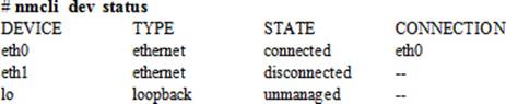
10. Show the connection status of eth1:
# nmcli dev status | grep eth1
eth1 ethernet connected eth1
11. Deactivate this interface and then reactivate:
# nmcli con down id eth1
# nmcli con up id eth1
Connection successfully activated (D-Bus active path: /org/freedesktop/NetworkManager/ActiveConnection/3)
12. Reboot the system:
# reboot
13. Verify the presence of eth1 assignments:
# ip addr
…… . .
3: eth1: <BROADCAST,MULTICAST,UP,LOWER_UP> mtu 1500 qdisc pfifo_fast state UP qlen 1000
link/ether 52:54:00:96:13:58 brd ff:ff:ff:ff:ff:ff
inet 192.168.0.121/24 brd 192.168.0.255 scope global eth1
valid_lft forever preferred_lft forever
inet6 fe80::5054:ff:fe96:1358/64 scope link
valid_lft forever preferred_lft forever
14. Open the hosts file and append the following entry to it:
# vi /etc/hosts
192.168.0.121 server2-eth1.example.com server2-eth1
You can use puTTY in Windows and attempt to access the server using this new IP.
Testing Network Connectivity with ping
After the new connections have been established on server1 and server2, we need to test whether the IP addresses are pingable and accessible from other systems. Log on to host1 or another RHEL system and run the ping (packet internet gropper) command. The ping command is used to check the network connectivity at the IP level when the physical connectivity is ok and proper IP address and network assignments are in place. This command sends out a series of 64-byte Internet Control Message Protocol (ICMP) test packets to the destination IP and waits for a response. With the –c option, we can specify the number of packets that we want to send.
The following will send two packets from host1 to 192.168.0.111 and two packets to 192.168.0.121:
# ping –c2 192.168.0.111
PING 192.168.0.111 (192.168.0.111) 56(84) bytes of data.
64 bytes from 192.168.0.111: icmp_seq=1 ttl=64 time=0.240 ms
64 bytes from 192.168.0.111: icmp_seq=2 ttl=64 time=0.269 ms
--- 192.168.0.111 ping statistics ---
2 packets transmitted, 2 received, 0% packet loss, time 999ms
rtt min/avg/max/mdev = 0.240/0.254/0.269/0.021 ms
# ping –c2 192.168.0.121
PING 192.168.0.121 (192.168.0.121) 56(84) bytes of data.
64 bytes from 192.168.0.121: icmp_seq=1 ttl=64 time=0.237 ms
64 bytes from 192.168.0.121: icmp_seq=2 ttl=64 time=0.234 ms
--- 192.168.0.121 ping statistics ---
2 packets transmitted, 2 received, 0% packet loss, time 999ms
rtt min/avg/max/mdev = 0.234/0.235/0.237/0.015 ms
Under the ping statistics, the outputs show the number of packets transmitted, received, and lost. The packet loss should be 0% and the round trip time should not be too high for a healthy connection. In general, we can use this command to test connectivity with a system’s own IP, the loopback IP, the default route, other systems on the local network, systems on a different network, and systems beyond the local network.
If ping fails in any of the situations, we need to check if the network adapter is seated properly, its driver installed, network cable secured appropriately, IP and subnet mask values set correctly, the default route configured right, and proper rules are defined in the firewall. We also need to verify entries in the hosts file and files in the /etc/sysconfig/network-scripts directory.
Overview of Graphical Network Administration Tools
RHEL7 offers Network Settings and Network Connections tools for graphical management of network interfaces. The Network Settings (or Control Network) is located in the Control Center and it may be accessed by clicking the network icon at the top right-hand corner in the GNOME desktop as shown in Figure 12-2 or by clicking Applications | System Tools | Settings | Network.
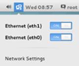
Figure 12-2 Network Icon
The Network Settings graphical tool allows us to view the status of available network interfaces, activating and deactivating them by sliding the bar to ON or OFF, add a new interface by clicking the + sign in the bottom left, delete an existing interface by highlighting an existing connection on the left and clicking the – sign in the bottom left, and modify an existing connection by selecting an existing connection on the left and clicking the gear wheel icon in the bottom right. See Figure 12-3.
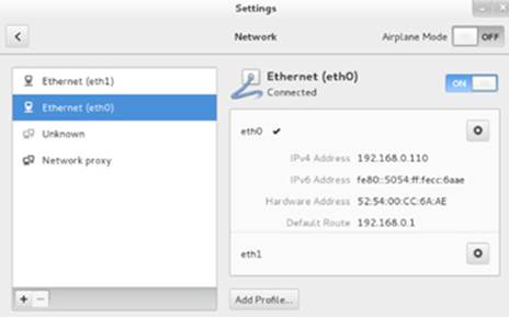
Figure 12-3 Network Settings
There are five types of network connections that we can add with this tool. These are VPN, Bond, Team, Bridge, and VLAN. Choosing any one of them brings up a new window with four tabs available in it. Figure 12-4 shows the window when we choose to add a Bridge. One of the three tabs is specific to the type of connection chosen; the rest are common for all interface types. Each tab allows us to enter necessary configuration information, including user-defined connection and interface names, static or dynamic IPv4 or IPv6 settings, DNS client and routing information, name of the firewall zone, and so on.
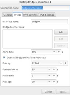
Figure 12-4 Network Settings / Add Connection
If we choose to modify a connection, the tabs will appear vertically on the left side, as shown in Figure 12-5. We can see the details for the interface; modify its IP, DNS, and routing information; reset all current assignments; and so on.
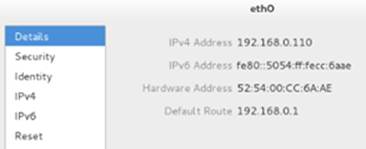
Figure 12-5 Network Settings / Modify a Connection
The Network Connections Editor tool provides pretty much the same functionality as the Network Settings tool we have just studied. Try running it with the nm-connection-editor command in an X terminal window and navigate to familiarize yourself with it.
The NTP Client
Network Time Protocol (NTP) is a networking protocol for synchronizing the system clock with more reliable remote providers of time. Using this protocol, a system can be configured as a server, peer, or client. The configuration changes to implement any of these roles are straightforward. In fact, the NTP client functionality comes pre-configured with the installation of NTP software. You simply need to enable and start the service, and your system will begin synchronizing its clock with one of the pre-defined timeservers.
The NTP client service can be modified by hand-editing a configuration file and restarting the service. This can alternatively be done using a graphical tool called System-Config-Date. You need to install the software packages for the base NTP software and, optionally, the GUI tool to configure your system to obtain time from a remote timeserver and maintain it. The software packages are referred to as ntp and system-config-date, respectively.
Activate the NTP Client
In order to establish the binding with a remote timeserver for time synchronization, install the ntp software on the system, along with the GUI tool:
# yum –y install ntp system-config-date
…… . .
Installed:
ntp.x86_64 0:4.2.6p5-18.el7
system-config-date.noarch 0:1.10.6-2.el7
Dependency Installed:
ntpdate.x86_64 0:4.2.6p5-18.el7
system-config-date-docs.noarch 0:1.0.11-4.el7
Complete!
By default, the NTP client functionality is pre-configured in the /etc/ntp.conf file, which is the primary configuration file for NTP in RHEL7. You simply need to enable and start the service. There are four default remote timeservers listed in the /etc/ntp.conf file, and they can be viewed as follows:
# grep ^server /etc/ntp.conf
server 0.rhel.pool.ntp.org iburst
server 1.rhel.pool.ntp.org iburst
server 2.rhel.pool.ntp.org iburst
server 3.rhel.pool.ntp.org iburst
EXAM TIP: As you will not have access to the outside network during the exam, you will need to point your system to an NTP server available on the local network. Simply comment the four server directives and add a single directive “server <hostname>” to the file. Replace <hostname> with an NTP server name or its IP address.
After the installation of the software is complete, run the following pair of commands to enable and start the service:
# systemctl enable ntpd
ln -s '/usr/lib/systemd/system/ntpd.service' '/etc/systemd/system/multi-user.target.wants/ntpd.service'
# systemctl start ntpd
The NTP daemon is now started. Execute the ntpq command with the –p switch to determine the association of your system with a timeserver:
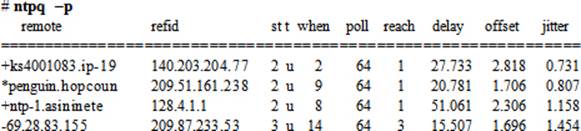
The output displays several timeservers. Your system has time association with the second server on the list prefixed with the * character.
Overview of the System-Config-Date GUI
The NTP client functionality may also be configured using the System-Config-Date graphical tool. This tool reads the definitions from the /etc/ntp.conf file and shows them graphically. In order to bring this tool up, execute system-config-date in an X terminal window or choose Applications | Sundry | System-Config-Date in the GNOME desktop. The System-Config-Date tool will open up as shown in Figure 12-6.
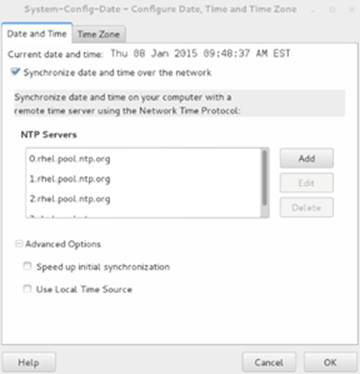
Figure 12-6 System-Config-Date GUI for NTP Client Configuration
Select the option “Synchronize date and time over the network” to enable the service, and click Add to add hostnames or IP addresses for remote timeservers that you wish your system clock to synchronize with. You may leave the default server entries there. Expand Advanced Options to view two additional choices. Select “Speed up initial synchronization” to instruct the tool to run the ntpdate command and immediately bring the local system clock close to that of the first NTP server listed. Choose “Use Local Time Source” if you wish to use the local system clock as the provider of time. Click OK when done.
Chapter 16 “Synchronizing Time with NTP” discusses NTP in more detail.
The OpenLDAP Client
Lightweight Directory Access Protocol (LDAP) is a trivial, simplified networking protocol for obtaining centrally-stored information over the network. LDAP is designed to retrieve information that may include user account data (username, location, address, phone number, job title, etc.), group information (group names, members, etc.), calendar services, and other system and network configuration data. It can be configured and used to authenticate users over the network rather than storing and managing users locally on individual systems. Most of this information is static and does not change frequently, making OpenLDAP a suitable solution for write-once-read-many-times applications. All this data, configuration items, and other similar information can be stored on the central server running an LDAP-supported database.
LDAP was derived from Directory Access Protocol (DAP), which is one of the protocols within X.500 specifications developed jointly by the International Telecommunication Union (ITU) and the International Organization for Standardization (ISO). One of the major disadvantages of DAP was its heavy requirement for computer hardware resources to work efficiently. LDAP (also referred to as X.500 Lite), on the other hand, is thinner and requires less client-side compute power. LDAP is platform-independent, which has contributed in its wide availability on a variety of vendor hardware platforms running heterogeneous operating system software.
LDAP is hierarchical; its structure is similar to the Linux/UNIX directory tree and DNS. It can be based on logical boundaries defined by geography or organizational arrangements. A typical LDAP directory structure for a company called ABC with domain abc.com and offices located in Canada, USA, UK, and Australia, may look analogous to what is shown in Figure 12-7.
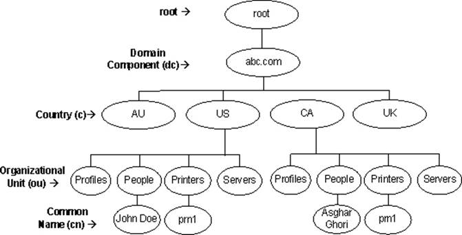
Figure 12-7 LDAP Directory Hierarchy
The top of the company is referred to as the root of the LDAP directory hierarchy. Underneath it, domain component (dc) is located, which is usually the name of the company; country (c) falls under the domain component; and organizational units (ou) separate categories of directory information and may or may not be country-specific. The actual information resides at the lowest level of the hierarchy, which may include resources, such as users, profiles, people, printers, servers, photos, text, URLs, pointers to information, binary data, and public key certificates.
Benefits of Using OpenLDAP
There are many benefits associated with implementing and using OpenLDAP solution in an enterprise. In addition to its wide availability and its flexible design to suit an organizational structure, OpenLDAP offers the following key benefits:
· Has a hierarchical directory structure that provides organizations with information and resources in a logical fashion.
· Allows the consolidation of common data and storing it in separate organizational units.
· Provides users and applications with a unified, standard interface to a single, extensible directory service, allowing rapid development and deployment of directory-enabled applications.
· Enables fast searches and cost-effective management of users and security.
· Maintains directory-wide consistent and non-redundant information.
OpenLDAP Terminology
Before we go any further on this topic, let’s review and comprehend the following key terms.
Directory: A directory is a kind of a specialized database that stores information about objects such as people, profiles, printers, and servers. This information is trivial and is intended for write-once, read-many operations. A directory organizes the information in a hierarchical fashion, making it easier for users to look up and retrieve needed data, and at the same time making it simpler from an administration standpoint.
Entry: An entry is a building block for a directory and represents a specific record in it. In other words, an entry is a collection of information consisting of one or more attributes for an object. An LDAP directory, for instance, might include entries for employees, contractors, printers, servers, and buildings. Each entry is recognized by its unique distinguished name in the LDAP hierarchy.
Attribute: An attribute is associated with one or more entries and is made up of an attribute type and an attribute value. The attribute type such as jobTitle represents the type of information the attribute contains. An attribute value is the specific information contained in that entry. For instance, a value for the jobTitle attribute type could be “director” or “associate director”. Table 12-4 lists some common attribute types.
|
Attribute Type |
Description / Attribute Value |
|
CommonName (cn) |
A common or full name of an entry, such as cn=John Doe. |
|
DomainComponent (dc) |
The distinguished name (DN) of a component in DNS such as dc=example and dc=com. |
|
Country (c) |
A country abbreviation such as c=ca. |
|
Mail (mail) |
An email address. |
|
Organization (o) |
The name of an organization such as o=redhat. |
|
OrganizationalUnit (ou) |
The name of a unit within an organization such as ou=Printers. |
|
Owner (owner) |
The owner of an entry such as cn=John Doe, ou=Printers, dc=example, and c=ca. |
|
Surname (sn) |
A person’s last name (or surname), such as Doe. |
|
TelephoneNumber (telephoneNumber) |
A telephone number, such as (123) 456-7890 or 1234567890. |
|
User ID (uid) |
A user’s login name. |
Table 12-4 Common LDAP Attribute Types
An attribute type can use long names or corresponding abbreviations as identified in the above table.
Matching Rule: A matching rule matches the attribute value sought against the attribute value stored in the directory in a search and compare task. For example, matching rules associated with the telephoneNumber attribute could cause “(123) 456-7890” to match with either “(123) 456-7890” or “1234567890”, or both.
Object Class: Each entry belongs to one or more object classes. An object class is a group of required and optional attributes that define the structure of an entry. For instance, an organizationalUser object class may include commonName and Surname as required attributes and telephoneNumber, UID, streetAddress, and userPassword as optional attributes.
Schema: A schema is a collection of attributes and object classes along with matching rules and syntax, and other related information, that defines rules surrounding them. A properly configured schema ensures data consistency and helps keep the data organized.
LDAP Data Interchange Format (LDIF): LDAP Data Interchange Format (LDIF) is a special format used for importing and exporting LDAP records among LDAP servers. The data is in the text format and consists of entries or alterations to entries, or a combination.
Each record is represented as a group of attributes, with each attribute listed on a separate line comprising “name:value” pair. The following is a sample directory entry, with attributes representing a record in LDIF:
dn: cn=John Doe,ou=People, c=ca,dc=abc
objectClass: inetLocalMailRecipient
sn: Doe
mail: john.doe@abc.com
cn: John Doe
givenName: John
uid: jdoe
telephoneNumber: (416) 123-4567
Distinguished Name: A Distinguished Name (DN) uniquely identifies an entry in the entire directory tree. It is similar in concept to the absolute pathname of a file in the Linux directory hierarchy. For instance, cn=prn1,ou=Printers,c=ca,dc=abc is the distinguished name for prn1 printer. A DN is thus a sequence of RDNs separated by commas.
Relative Distinguished Name: A Relative Distinguished Name (RDN), in contrast, represents individual components of a DN. It is similar in concept to the relative pathname of a file in the Linux directory hierarchy. As an example, the RDN for the printer prn1 under Printers located in Canada (See Figure 12-6) is cn=prn1. Similarly, the RDN for Printers is ou=Printers, the RDN for ca is c=ca, and that for abc is dc=abc.
OpenLDAP Roles
There are four roles – server, replica, client, and referral – that systems within an LDAP environment may perform. One system can be configured to execute more than one role.
Server: A server is the central system that holds the LDAP directory information. It may be referred to as the master server. There must be at least one such server in the environment.
Replica: A replica is the system that receives a copy of the information that the LDAP server maintains. It may be referred to as a slave server. It is recommended to have at least one replica available on the network for enhanced availability and load sharing.
Client: A client is the system that binds itself with a server or replica to establish a communication session to perform queries on directory entries and carry out necessary modifications.
Referral: A referral is an entity on an LDAP server that redirects a client request to some other LDAP server or replica if it is unable to fulfill the request. It contains names and locations of other LDAP servers that might store the requested information.
OpenLDAP Client Packages
In order to implement and use OpenLDAP client functionality, software packages openldap, openldap-clients, and nss-pam-ldapd are required on the system. Furthermore, we have the option of choosing between one of two types of authentication services that are available in RHEL7. These services are System Security Services Daemon (SSSD) and Name Service Local Caching Daemon (NSLCD), and their purpose is to facilitate user authentication against a directory server. We can use either of them; however, the use of SSSD is preferred. Therefore, in addition to the three OpenLDAP packages, we will also need the sssd package and all the packages that it relies on. Together, these software bring with them necessary configuration files, library routines, and tools to support the implementation. The openldap package includes library and configuration files, the openldap-clients package contains client utilities such as ldapadd, ldapmodify, ldapcompare, ldapsearch, and ldapdelete to perform add, modify, compare, search, and delete operations on the directory, the nss-pam-ldapd package comprises of a library routine that must be installed for LDAP support to work properly, and the sssd package installs the sssd service on the client to support identity lookups and user authentication, authorization, and password modifications. We will need either TLS or LDAPs to establish an encrypted channel between the client and the server.
RHEL7 provides two more packages that are used to set up user identity and authentication on the client using LDAP, NIS, Kerberos, and a few other services. These packages are authconfig and authconfig-gtk, and they contain the authconfig command and its graphical equivalent system-config-authentication, a.k.a. authconfig-gtk, (the Authentication Configuration tool), respectively. The authconfig package also includes the authconfig-tui text tool that is equivalent to the graphical tool.
OpenLDAP Client Configuration Files
With the installation of the OpenLDAP client packages, configuration file /etc/openldap/ldap.conf becomes available on the system. This file sets system-wide default settings for LDAP client operations. Another file /etc/sssd/sssd.conf is created at the time of client configuration to store control data for the sssd daemon.
Table 12-5 lists and describes some key directives that are used in the ldap.conf file.
|
Directive |
Description |
|
BASE |
Sets the base DN to be used for LDAP operations. |
|
URI |
Specifies the URI for the LDAP server. |
|
TLS_CACERTDIR |
Specifies the location where TLS certificates are stored. The default location is in /etc/openldap/cacerts directory. |
Table 12-5 /etc/openldap/ldap.conf File
The authconfig Command
The LDAP client configuration can be done using the authconfig command. This command offers several options; Table 12-6 lists and describes the ones that affect LDAP client setup only.
|
Option |
Description |
|
--enableldap / --disableldap |
Enables/disables LDAP for user information. |
|
--enableldapauth / --disableldapauth |
Enables/disables LDAP for user authentication. |
|
--enableldaptls / --disableldaptls |
Enables/disables the use of TLS with LDAP. |
|
--enablesssd / --disablesssd |
Enables/disables the use of SSSD for user information. |
|
--ldapserver |
Specifies the LDAP server hostname or IP. |
|
--ldapbasedn |
Sets the default LDAP base distinguished name. |
|
--test |
Displays new settings without updating the configuration. |
|
--update |
Updates the configuration with the supplied information. This option should be specified each time a change is desired in the configuration. |
Table 12-6 The authconfig Command
We are going to use this command to configure an LDAP client in our next exercise.
Exercise 12-3: Configure LDAP Client to Obtain User and Group Information
This exercise should be done on server1.
It is assumed that server2 has the OpenLDAP service, such as FreeIPA or Red Hat Directory Server, configured and running, and it has a user account ldapuser1 and group account dba available to test authentication.
In this exercise, you will configure the LDAP client with the authconfig command. You will ensure that the client is autostarted at each system reboot. You will run appropriate commands to test it.
1. Install the necessary LDAP client software packages:
# yum –y install openldap openldap-clients nss-pam-ldapd sssd authconfig
2. Set up the client and update the configuration files. Enable the use of LDAP, LDAP authentication, and SSSD. Specify the hostname for the LDAP server and the base DN.
# authconfig --enableldap --enableldapauth --ldapserver=ldap://server2.example.com \ --enablesssd --ldapbasedn=”dc=example,dc=com” --update
3. Show the contents of the /etc/sssd/sssd.conf and /etc/openldap/ldap.conf files:
# cat /etc/sssd/sssd.conf
[domain/default]
autofs_provider = ldap
cache_credentials = True
krb5_realm = #
ldap_search_base = dc=example,dc=com
id_provider = ldap
auth_provider = ldap
chpass_provider = ldap
ldap_uri = ldap://server2.example.com/
ldap_id_use_start_tls = True
ldap_tls_cacertdir = /etc/openldap/cacerts
[sssd]
services = nss, pam, autofs
config_file_version = 2
domains = default
[nss]
[pam]
[sudo]
[autofs]
[ssh]
[pac]
# grep –v ^# /etc/openldap/ldap.conf
TLS_CACERTDIR /etc/openldap/cacerts
URI ldap://server2.example.com/
BASE dc=example,dc=com
4. Edit the /etc/nsswitch.conf file and ensure the passwd, shadow, and group entries look like the following (for details on this file, see Chapter 24 “Configuring DNS”):
passwd: files sss
shadow: files sss
group: files sss
5. Enable the sssd service to autostart at system reboots:
# systemctl enable sssd
6. Start the sssd service, which will also start the OpenLDAP client on the system:
# systemctl start sssd
7. Test group data by pulling dba group information from the server with the getent command (the getent command displays entries from the databases listed in the /etc/nsswitch.conf file):
# getent group dba
8. Test authentication by logging in as ldapuser1 from server1 to server2, using the ssh command:
# ssh ldapuser1@server2
If you want the client to use TLS for secure communication with the server, add --enableldaptls and --ldaploadcacert options with the authconfig command in step 2. You will need to ensure that a valid certificate is stored on server2 at an appropriate location.
Moreover, you may want to use Kerberos for authentication in place of LDAP’s password authentication method. For this, supply options specific to Kerberos with the authconfig command and do not specify the --ldapauth option. See Chapter 17 “Working with Firewalld and Kerberos” for details on Kerberos client setup.
EXAM TIP: Use either the graphical (authconfig-gtk or system-config-authentication) or the text (authconfig-tui) Authentication Configuration tool for LDAP client setup with or without Kerberos.
Overview of Graphical Authentication Configuration Tool
The Authentication Configuration tool is used for convenience if we do not feel comfortable with using the authconfig command. This graphical tool is easier to use provided we have the data handy that we want entered. This tool may be invoked by running the authconfig-gtk or the system-config-authentication command in an X terminal window or choosing Applications | Sundry | Authentication in the GNOME desktop. It will open up as shown in Figure 12-8.
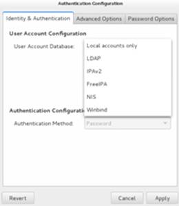
Figure 12-8 Authentication Configuration Tool
There are three tabs across the top for configuring identity & authentication, advanced options, and password options. As we know, this tool allows us to access user information stored on various types of databases and to configure the service to be used for user authentication purpose. For any user account database that we select from the drop-down list under Identification & Authentication, we see the window size changes providing room to enter data specific to the selected database. Figure 12-9 depicts the window for LDAP.
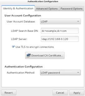
Figure 12-9 Authentication Configuration Tool – LDAP Client Configuration
Similarly, we can use a method for authentication. For instance, LDAP can use either the LDAP password or Kerberos password. If the latter is chosen, we will need to enter Kerberos server details.
The Advanced Options provide additional configuration selections for authentication, and the Password Options tab allows us to set password rules.
Chapter Summary
This chapter discussed networking and OpenLDAP client configuration. It started by providing an understanding of various essential networking terms to build the foundation for networking topics going forward. Topics such as the hostname, IPv4, IPv6, network classes, subnetting, subnet mask, protocol, and Ethernet address were covered.
We configured one network interface on server1 and another one on server2 using commands. We had an overview of the graphical tool. We reviewed various files involved in the configuration. We performed activation and deactivation of interfaces manually and defined the IP and hostname mappings in the hosts databases on both servers. We used tools to test network connectivity.
We covered the configuration of an NTP client on our system to synchronize the clock with a more accurate provider of time. We looked at how to enable the service using commands and the graphical setup tool.
Finally, we studied OpenLDAP: concepts, benefits, terminology, and roles. We performed an exercise to configure the LDAP client service on our system, and then tested it. We looked at the graphical authentication tool and saw how to use it to configure the OpenLDAP client.
Chapter Review Questions
1. What is a relative distinguished name?
2. What is meant by the object Entry in LDAP terminology?
3. The NTP client is pre-configured when the ntp software is installed on the system. We just need to start the service to begin synchronizing the clock. True or False?
4. Which class of IP addresses has the least number of node addresses?
5. What is the use of ifup and ifdown commands?
6. Which command may we use to display the hardware address of a network interface?
7. Which directory does the Network Manager store the interface configuration files?
8. Which file defines the protocols in the system?
9. List three benefits of using LDAP as a directory server.
10. What is the purpose of the ONBOOT directive in the interface configuration file?
11. The /etc/hosts file maintains the hostname to hardware address mappings. True or False?
12. Which file contains service, port, and protocol mappings?
13. What is the name of the graphical NTP client configuration tool?
14. What would the ip addr command produce?
15. Which command can be run at the command prompt in an X terminal window to bring up the graphical Network Connections tool?
16. List any two benefits of subnetting.
17. The ip neighbor command uses the RARP protocol to provide MAC to IP address mappings. True or False?
18. What would the command system-config-authentication do?
Answers to Chapter Review Questions
1. The relative distinguished name represents individual components of a DN.
2. The object Entry represents a specific record in the LDAP directory.
3. True.
4. The C class has the least number of node addresses.
5. The purpose of these two commands is to activate and deactivate an interface.
6. The ip command.
7. The /etc/sysconfig/network-scripts directory.
8. The /etc/protocols file.
9. Three benefits are access to uniform information, centralized storage for information, and user authentication.
10. The purpose of this directive is to tell the boot scripts whether to activate this interface.
11. False. This file maintains hostname to IP address mappings.
12. The /etc/services file.
13. The name of the graphical NTP client configuration tool is System-Config-Date.
14. This command will display information about interfaces including IP and hardware address information.
15. The command to bring up the graphical Network Connections tool is nm-connection-editor.
16. Better manageability and less traffic.
17. False. It uses ARP protocol.
18. This command will bring up the graphical Authentication Configuration tool.
DIY Challenge Labs
The following labs are useful to strengthen most of the concepts and topics learned in this chapter. It is expected that you perform these labs without any additional help. A step-by-step guide is not provided, as the implementation of these labs requires the knowledge that has been presented in this chapter. Use defaults or your own thinking for missing information.
Lab 12-1: Assign a New IP to the System
Remove the current IP assignments for eth0 on server1.example.com and replace them with something different but on the same subnet. Apply the new IP information using appropriate tools and test it using the ip and ping commands, then edit appropriate files to make this modification persistent across reboots. Activate and deactivate the interface manually. Reboot the system and verify the new IP using appropriate commands.
All materials on the site are licensed Creative Commons Attribution-Sharealike 3.0 Unported CC BY-SA 3.0 & GNU Free Documentation License (GFDL)
If you are the copyright holder of any material contained on our site and intend to remove it, please contact our site administrator for approval.
© 2016-2026 All site design rights belong to S.Y.A.