RHCSA & RHCE Red Hat Enterprise Linux 7: Training and Exam Preparation Guide (EX200 and EX300), Third Edition (2015)
Part II. RHCE Section
Chapter 15. Configuring Bonding, Teaming, IPv6, and Routing
This chapter describes the following major topics:
· Overview of link aggregation, and interface bonding and teaming
· Configure interface bonding manually and via NetworkManager CLI
· Configure interface teaming manually and via NetworkManager CLI
· Use graphical tools for bonding and teaming setup
· Understand IPv6 and how to view its assignments
· Configure and test IPv6 addresses
· Introduction to routing and routing table
· Add static routes manually and by editing appropriate files
RHCE Objectives:
31. Configure networking and hostname resolution statically or dynamically
55. Use network teaming or bonding to configure aggregate network links between two Red Hat Enterprise Linux systems
56. Configure IPv6 addresses and perform basic IPv6 troubleshooting
57. Route IP traffic and create static routes
Link aggregation is a technique by which two or more network interfaces are logically configured to provide higher performance using their combined bandwidth and fault tolerance should all but one of them fail. Two common methods for link aggregation are bonding and teaming, and both are supported natively in RHEL7.
The continuous expansion of the Internet and a mushrooming demand for IP addresses has opened doors for the use of IPv6 addresses. The current deployment of IPv6 is limited; however, it will not be uncommon in the near future to see computing devices using these addresses.
Routing selects network paths for the transmission of IP traffic between two computing devices that may be located thousands of kilometers apart on distinct networks. Routers are specialized hardware devices that are employed for data routing purposes, and they are deployed in abundance to route Internet, business, and personal traffic. A RHEL system can also be configured to provide routing, but with limited capability.
Link Aggregation
Link aggregation is a term used in corporate networks to combine the capabilities of two or more physical or virtual Ethernet network interfaces to function as a single logical network pipe. The resultant aggregate offers three major advantages: better throughput, load balancing across all interfaces, and fault tolerance in the event all but one interface in the aggregate fail. RHEL7 supports two link aggregation methods that are referred to as bonding and teaming. Support for bonding has been around in RHEL for years; however, with the release of RHEL7, we now also have the ability to form interface teaming. If we compare the features presented by both methods, we will observe that teaming is a better option. In fact, RHEL7 offers a tool called bond2team for those who wish to migrate from their existing bonding setups to teaming.
Bonding and teaming can be configured with IPv4 and IPv6 assignments by editing files, and using tools such as the NetworkManager CLI or TUI, or the GNOME Network Connections GUI. Additional tasks such as activating and deactivating logical channels can also be performed with these and other OS tools as well. Chapter 12 “Administering Network Interfaces and Network Clients” discussed these tools in detail. A repeat of them will be evident in upcoming exercises.
Interface Bonding
Interface bonding provides the ability to bind two or more network interfaces together into a single, logical bonded channel that acts as the master for all slave interfaces that are added to it. An IP address is applied to the bond rather than to individual slaves within the bond. Users and applications will see the bond device as the connection to use rather than the individual interfaces within it.
The support for bonding is integrated entirely into the kernel as a loadable module. This module is called bonding. A bonded channel is configured to use one of several modes of operation that dictate its overall behavior. Some of the modes are described in Table 15-1.
|
Mode of Operation |
Description |
|
Round-robin |
This mode moves network traffic serially starting with the first slave and going to the last, and then back to the first. This mode supports both load balancing and fault tolerance. It is specified as balance-rr. |
|
Active-backup |
Only one slave is active at a time, and all others are available but in passive mode. In the event that the active slave fails, one of the passive slaves takes over and becomes active. This mode of operation does not provide load balancing; however, it does support fault tolerance. It is specified as active-backup. |
|
XOR |
This mode uses the source and destination Ethernet addresses to transfer network traffic. This mode provides both load balancing and fault tolerance. It is specified as balance-xor. |
|
Broadcast |
This mode transmits network traffic on all slaves. This mode provides fault tolerance only. It is specified as broadcast. |
Table 15-1 Modes of Operation for Bonding Channel
Exercise 15-1: Configure Interface Bonding by Editing Files
This exercise should be done on server1. However, the new interface allocation will be done on host1.
The allocation of a pair of virtual network interfaces to server1 and the formation of a bonding channel with IP 192.168.1.110 was mentioned in Chapter 01 “Installing RHEL7 on Physical Computer Using Local DVD”.
In this exercise, you will add two new interfaces on 192.168.1.0/24 network to server1 and call them eth2 and eth3. You will form a bond by creating configuration files and executing appropriate commands to activate it. You will reboot the system to verify bond activation. You will assign hostname server1bond.example.org with alias server1bond. You will add IP and hostname mapping to the hosts table.
1. Open the virtual console for server1 on host1. Click “Show virtual hardware details” | Add Hardware | Network. Select Source device “Virtual network ‘rhnet_virt’ : NAT” from the drop-down list and Device model virtio. We created this network in Chapter 06 “Configuring Server Virtualization and Network Installing RHEL7”. Leave the MAC address to the default. Click Finish to complete the new interface assignment.
2. Repeat step 1 and add another interface.
3. Log on to server1 and run the ip command to check the new interfaces:
# ip addr
…… . .
4: eth2: <BROADCAST,MULTICAST,UP,LOWER_UP> mtu 1500 qdisc pfifo_fast state UP qlen 1000
link/ether 52:54:00:0c:ec:ff brd ff:ff:ff:ff:ff:ff
5: eth3: <BROADCAST,MULTICAST,UP,LOWER_UP> mtu 1500 qdisc pfifo_fast state UP qlen 1000
link/ether 52:54:00:28:91:f0 brd ff:ff:ff:ff:ff:ff
The output indicates the presence of two new interfaces by the name eth2 and eth3.
4. Load the bonding driver called “bonding” in the kernel with the modprobe command if it is not already loaded, and verify with the modinfo command:
|
# modprobe bonding |
|
|
# modinfo bonding |
|
|
filename: |
/lib/modules/3.10.0-123.el7.x86_64/kernel/drivers/net/bonding/bonding.ko |
|
alias: |
rtnl-link-bond |
|
author: |
Thomas Davis, tadavis@lbl.gov and many others |
|
description: |
Ethernet Channel Bonding Driver, v3.7.1 |
|
version: |
3.7.1 |
|
license: |
GPL |
|
srcversion: |
E52AE00A79EA6FEFB5BF718 |
|
depends: |
|
|
intree: |
Y |
|
vermagic: |
3.10.0-123.el7.x86_64 SMP mod_unload modversions |
|
signer: |
Red Hat Enterprise Linux kernel signing key |
|
sig_key: |
00:AA:5F:56:C5:87:BD:82:F2:F9:9D:64:BA:83:DD:1E:9E:0D:33:4A |
|
sig_hashalgo: |
sha256 |
|
parm: max_bonds: |
Max number of bonded devices (int) |
|
…… . . |
|
5. Generate UUIDs for both new interfaces using the uuidgen command:
# uuidgen eth2
15d44a70-554d-49c6-9ea0-c1ba3200f797
# uuidgen eth3
2f9aec97-d5d1-4fe1-81b0-60e6080c0352
6. Use the vi editor to create a file called ifcfg-bond0 in the /etc/sysconfig/network-scripts directory for bond0 with the following settings. Use the interface type Bond. This virtual device will serve as the bonding master with round-robin as the load balancing technique. The rest of the settings are self-explanatory.
# cd /etc/sysconfig/network-scripts
# vi ifcfg-bond0
DEVICE=bond0
NAME=bond0
TYPE=Bond
BONDING_MASTER=yes
BONDING_OPTS="mode=balance-rr"
ONBOOT=yes
BOOTPROTO=none
IPADDR=192.168.1.110
NETMASK=255.255.255.0
GATEWAY=192.168.1.1
IPV4_FAILURE_FATAL=no
IPV6INIT=no
7. Use the vi editor to create ifcfg-eth2 and ifcfg-eth3 files in the /etc/sysconfig/network-scripts directory for eth2 and eth3 interfaces with the following settings. Set the MASTER directive to bond0. Both interfaces will act as slaves with no IP addresses assigned to them.
# vi ifcfg-eth2
DEVICE=eth2
NAME=eth2
UUID=15d44a70-554d-49c6-9ea0-c1ba3200f797
TYPE=Ethernet
ONBOOT=yes
MASTER=bond0
SLAVE=yes
# vi ifcfg-eth3
DEVICE=eth3
NAME=eth3
UUID=2f9aec97-d5d1-4fe1-81b0-60e6080c0352
TYPE=Ethernet
ONBOOT=yes
MASTER=bond0
SLAVE=yes
8. Deactivate and reactivate bond0 with the ifdown and ifup commands:
# ifdown bond0 ; ifup bond0
Connection successfully activated (D-Bus active path: /org/freedesktop/NetworkManager/ActiveConnection/3)
9. Check the status of bond0 and the slaves with the ip command. It should also show the assigned IP.
# ip addr
…… . .
4: eth2: <BROADCAST,MULTICAST,UP,LOWER_UP> mtu 1500 qdisc pfifo_fast state UP qlen 1000
link/ether 52:54:00:0c:ec:ff brd ff:ff:ff:ff:ff:ff
5: eth3: <BROADCAST,MULTICAST,UP,LOWER_UP> mtu 1500 qdisc pfifo_fast state UP qlen 1000
link/ether 52:54:00:28:91:f0 brd ff:ff:ff:ff:ff:ff
6: bond0: <NO-CARRIER,BROADCAST,MULTICAST,MASTER,UP> mtu 1500 qdisc noqueue state UP
link/ether ba:73:ec:58:d5:c1 brd ff:ff:ff:ff:ff:ff
inet 192.168.1.110/24 brd 192.168.1.255 scope global bond0
valid_lft forever preferred_lft forever
10. Restart the system to ensure the configuration survives system reboots:
# reboot
11. Repeat step 9 to verify the bond and IP assignments.
12. Open the hosts file and append the following entry to it:
# vi /etc/hosts
192.168.1.110 server1bond.example.org server1bond
Using the nmcli Command to Configure Bonding and Teaming
The nmcli command is a NetworkManager service tool that allows you to add, show, alter, delete, start, and stop bonding and teaming interfaces, and control and report their status. This tool operates on network connections and devices in addition to a few other object types. For additional information, Chapter 12 “Administering Network Interfaces and Network Clients”.
Exercise 15-2: Configure Interface Bonding with NetworkManager CLI
This exercise is intended to be done on server2; however, the new interface allocation will be done on host1.
The allocation of a pair of virtual network interfaces to server2 and the formation of a bonded channel with IP 192.168.1.120 was mentioned in Chapter 01 “Installing RHEL7 on Physical Computer Using Local DVD”.
In this exercise, you will add two new interfaces on 192.168.1.0/24 network to server2 and call them eth2 and eth3. You will configure a bond and activate it using the NetworkManager commands. You will reboot the system to verify bond activation. You will assign hostnameserver2bond.example.org with alias server2bond. You will add IP and hostname mapping to the hosts table. Finally, you will run a ping test from server2bond to server1bond to confirm connectivity.
1. Open the virtual console for server2 on host1. Click “Show virtual hardware details” | Add Hardware | Network. Select Source device “Virtual network ‘rhnet_virt’ : NAT” from the drop-down list and Device model virtio. We created this network in Chapter 06. Leave the MAC address to the default. Click Finish to complete the new interface assignment.
2. Repeat step 1 and add another interface.
3. Check the operational status of the NetworkManager service:
# systemctl status NetworkManager
NetworkManager.service - Network Manager
Loaded: loaded (/usr/lib/systemd/system/NetworkManager.service; enabled)
Active: active (running) since Sun 2014-12-14 00:13:36 EST; 3min 32s ago
Main PID: 909 (NetworkManager)
CGroup: /system.slice/NetworkManager.service
└─909 /usr/sbin/NetworkManager --no-daemon
…… . .
4. List all available network interfaces including the ones just added:
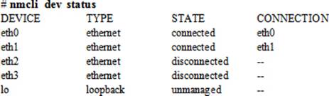
The output indicates the presence of two new interfaces by the name eth2 and eth3.
5. Load the bonding driver in the kernel with the modprobe command if it is not already loaded, and verify with the modinfo command:
|
# modprobe bonding |
|
|
# modinfo bonding |
|
|
filename: |
/lib/modules/3.10.0-123.el7.x86_64/kernel/drivers/net/bonding/bonding.ko |
|
alias: |
rtnl-link-bond |
|
author: |
Thomas Davis, tadavis@lbl.gov and many others |
|
description: |
Ethernet Channel Bonding Driver, v3.7.1 |
|
version: |
3.7.1 |
|
license: |
GPL |
|
srcversion: |
E52AE00A79EA6FEFB5BF718 |
|
depends: |
|
|
intree: |
Y |
|
vermagic: |
3.10.0-123.el7.x86_64 SMP mod_unload modversions |
|
signer: |
Red Hat Enterprise Linux kernel signing key |
|
sig_key: |
00:AA:5F:56:C5:87:BD:82:F2:F9:9D:64:BA:83:DD:1E:9E:0D:33:4A |
|
sig_hashalgo: |
sha256 |
|
parm: max_bonds: |
Max number of bonded devices (int) |
|
…… . . |
|
6. Add a logical interface called bond0 of type bond with connection name bond0, load balancing policy round-robin, IP address 192.168.1.120/24, and gateway 192.168.1.1:
# nmcli con add type bond con-name bond0 ifname bond0 mode balance-rr \
ip4 192.168.1.120/24 gw4 192.168.1.1
Connection 'bond0' (88b9e708-8dee-4fe8-8b8f-1c989a0bab4a) successfully added.
This command has added a bond device and created an ifcfg-bond0 file in the /etc/sysconfig/network-scripts directory with all necessary directives.
7. Show the contents of the ifcfg-bond0 file:
# cat /etc/sysconfig/network-scripts/ifcfg-bond0
DEVICE=bond0
BONDING_OPTS=mode=balance-rr
TYPE=Bond
BONDING_MASTER=yes
BOOTPROTO=none
IPADDR0=192.168.1.120
PREFIX0=24
GATEWAY0=192.168.1.1
DEFROUTE=yes
IPV4_FAILURE_FATAL=no
IPV6INIT=yes
IPV6_AUTOCONF=yes
IPV6_DEFROUTE=yes
IPV6_PEERDNS=yes
IPV6_PEERROUTES=yes
IPV6_FAILURE_FATAL=no
NAME=bond0
UUID=88b9e708-8dee-4fe8-8b8f-1c989a0bab4a
ONBOOT=yes
8. Add eth2 and eth3 interfaces as slaves to the master bond device bond0:
# nmcli con add type bond-slave ifname eth2 master bond0
Connection 'bond-slave-eth2' (210b1f1e-3e3b-42af-937b-c42088cabf7d) successfully added.
# nmcli con add type bond-slave ifname eth3 master bond0
Connection 'bond-slave-eth3' (d5c1c635-2971-43a7-b0ce-efe7c5dd44c7) successfully added.
This command has added eth2 and eth3 interfaces as slaves to bond0, and has created ifcfg-bond-slave-eth2 and ifcfg-bond-slave-eth3 files in the /etc/sysconfig/network-scripts directory with all necessary directives.
9. Show the contents of the ifcfg-bond-slave-eth2 and ifcfg-bond-slave-eth3 files:
# cat /etc/sysconfig/network-scripts/ifcfg-bond-slave-eth2
TYPE=Ethernet
NAME=bond-slave-eth2
UUID=210b1f1e-3e3b-42af-937b-c42088cabf7d
DEVICE=eth2
ONBOOT=yes
MASTER=bond0
SLAVE=yes
# cat /etc/sysconfig/network-scripts/ifcfg-bond-slave-eth3
TYPE=Ethernet
NAME=bond-slave-eth3
UUID=d5c1c635-2971-43a7-b0ce-efe7c5dd44c7
DEVICE=eth3
ONBOOT=yes
MASTER=bond0
SLAVE=yes
10. Activate bond0. By default, the slave devices are already up and operational. If not, you will have to activate them prior to starting the bond.
# nmcli con up bond0
Connection successfully activated (D-Bus active path: /org/freedesktop/NetworkManager/ActiveConnection/5)
11. Check the new connection and IP assignments:
# ip addr | grep bond0
4: eth2: <BROADCAST,MULTICAST,SLAVE,UP,LOWER_UP> mtu 1500 qdisc pfifo_fast master bond0 state UP qlen 1000
5: eth3: <BROADCAST,MULTICAST,SLAVE,UP,LOWER_UP> mtu 1500 qdisc pfifo_fast master bond0 state UP qlen 1000
6: bond0: <BROADCAST,MULTICAST,MASTER,UP,LOWER_UP> mtu 1500 qdisc noqueue state UP
inet 192.168.1.120/24 brd 192.168.1.255 scope global bond0
The output confirms the IP address assignment to the bond and the operational status of the interface devices.
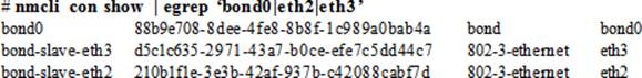
12. Show the connection information for the bond and slaves:
13. Restart the system to confirm that the configuration remains persistent across reboots:
# reboot
14. Run steps 11 and 12 again to verify the bond and IP assignments.
15. Open the hosts file and append entries for both server1bond and server2bond to it:
# vi /etc/hosts
192.168.1.110 server1bond.example.org server1bond
192.168.1.120 server2bond.example.org server2bond
16. Copy this hosts file to server1 so that both systems have the same entries:
# scp /etc/hosts server1:/etc
17. Test network connectivity by transmitting ping traffic (use –c 3 to send three packets) from server2bond to server1bond:
# ping –c 3 server1bond
PING server1bond.example.com (192.168.1.110) 56(84) bytes of data.
64 bytes from server1bond.example.com (192.168.1.110): icmp_seq=1 ttl=64 time=0.235 ms
64 bytes from server1bond.example.com (192.168.1.110): icmp_seq=2 ttl=64 time=0.247 ms
64 bytes from server1bond.example.com (192.168.1.110): icmp_seq=3 ttl=64 time=0.306 ms
--- server1bond.example.com ping statistics ---
3 packets transmitted, 3 received, 0% packet loss, time 2000ms
rtt min/avg/max/mdev = 0.235/0.262/0.306/0.036 ms
Interface Teaming
Interface teaming is introduced in RHEL7 as an additional choice to implement enhance throughput and fault tolerance at the network interface level. While bonding is still supported in RHEL7, it is not in conflict with teaming in any way. There are certain differences between the two though. Bonding has been in RHEL for a long period, and it is matured and robust. Teaming, in comparison, is a new implementation. Teaming handles the flow of network packets faster than bonding does. And unlike bonding, which is accomplished purely in the kernel space and provides no user control over its operation, teaming only requires the integration of the essential code into the kernel and the rest is implemented via the teamd daemon, which gives users the ability to control it with the teamdctl command.
EXAM TIP: Teaming is preferred over bonding as a method of establishing link aggregation.
Like bonding, teaming can be configured by either editing the files directly or using the NetworkManager CLI, TUI, or GNOME Network Connection GUI.
Exercise 15-3: Configure Interface Teaming by Editing Files
This exercise should be done on server1. However, the new interface allocation will be done on host1.
The allocation of a pair of virtual network interfaces to server1 and the formation of a teamed channel with IP 192.168.2.110 was mentioned in Chapter 01 “Installing RHEL7 on Physical Computer Using Local DVD”.
In this exercise, you will add two new interfaces on 192.168.2.0/24 network to server1, and will call them eth4 and eth5. You will generate UUIDs for the new interfaces. You will form a team of the two interfaces by creating configuration files and executing appropriate commands to activate and confirm it. You will reboot the system to verify team activation. You will assign the hostname server1team.example.net with alias server1team. You will add IP and hostname mapping to the hosts table.
1. Open the virtual console for server1 on host1. Click “Show virtual hardware details” | Add Hardware | Network. Select Source device “Virtual network ‘rhnet_virsh’ : NAT” from the drop-down list and Device model virtio. We created this network in Chapter 06. Leave the MAC address to the default. Click Finish to complete the new interface assignment.
2. Repeat step 1 and add another interface.
3. Log on to server1 and run the ip command to check the new interfaces:
# ip addr
…… . .
6: eth4: <BROADCAST,MULTICAST,UP,LOWER_UP> mtu 1500 qdisc pfifo_fast state UP qlen 1000
link/ether 52:54:00:47:30:d7 brd ff:ff:ff:ff:ff:ff
7: eth5: <BROADCAST,MULTICAST,UP,LOWER_UP> mtu 1500 qdisc pfifo_fast state UP qlen 1000
link/ether 52:54:00:47:30:d7 brd ff:ff:ff:ff:ff:ff
The output indicates the presence of two new interfaces by the name eth4 and eth5.
4. Install the team software:
# yum –y install teamd
5. Load the team driver in the kernel with the modprobe command if it is not already loaded, and verify with the modinfo command:
|
# modprobe team |
|
|
# modinfo team |
|
|
filename: |
/lib/modules/3.10.0-123.el7.x86_64/kernel/drivers/net/team/team.ko |
|
alias: |
rtnl-link-team |
|
description: |
Ethernet team device driver |
|
author: |
Jiri Pirko <jpirko@redhat.com> |
|
license: |
GPL v2 |
|
srcversion: |
39F7B52A85A880B5099D411 |
|
depends: |
|
|
intree: |
Y |
|
vermagic: |
3.10.0-123.el7.x86_64 SMP mod_unload modversions |
|
signer: |
Red Hat Enterprise Linux kernel signing key |
|
sig_key: |
00:AA:5F:56:C5:87:BD:82:F2:F9:9D:64:BA:83:DD:1E:9E:0D:33:4A |
|
sig_hashalgo: |
sha256 |
6. Generate UUIDs for both new interfaces and a logical team device called team0 using the uuidgen command:
# uuidgen eth4
bc85731f-8f4e-4ccd-9af7-deb0da7d37e7
# uuidgen eth5
f2823a4f-8933-408d-8969-ec20c0ee4b91
7. Use the vi editor and create a file called ifcfg-team0 in the /etc/sysconfig/network-scripts directory for team0 with the following settings. Use the interface type Team. This virtual device will serve as the teaming master with round-robin as the load balancing technique. The rest of the settings are self-explanatory.
# cd /etc/sysconfig/network-scripts
# vi ifcfg-team0
DEVICE=team0
NAME=team0
DEVICETYPE=Team
TEAM_CONFIG='{"runner": {"name": "activebackup"}, "link_watch": {"name":"ethtool"}}'
ONBOOT=yes
PREFIX=24
BOOTPROTO=none
IPADDR0=192.168.2.110
NETMASK0=255.255.255.0
GATEWAY0=192.168.2.1
8. Use the vi editor and create ifcfg-eth4 and ifcfg-eth5 files in the /etc/sysconfig/network-scripts directory for eth4 and eth5 interfaces with the following settings. Use the UUIDs generated in step 5 for the interfaces and set the TEAM_MASTER directive to team0. Both interfaces will act as slaves with no IP addresses assigned to them.
# vi ifcfg-eth4
DEVICE=eth4
NAME=eth4
UUID=bc85731f-8f4e-4ccd-9af7-deb0da7d37e7
DEVICETYPE=TeamPort
ONBOOT=yes
TEAM_MASTER=team0
TEAM_PORT_CONFIG=’{“prio”: 9}’
# vi ifcfg-eth5
DEVICE=eth5
NAME=eth5
UUID=f2823a4f-8933-408d-8969-ec20c0ee4b91
DEVICETYPE=TeamPort
ONBOOT=yes
TEAM_MASTER=team0
TEAM_PORT_CONFIG=’{“prio”: 10}’
9. Activate team0 with the ifup command:
# ifup team0
Connection successfully activated (D-Bus active path: /org/freedesktop/NetworkManager/ActiveConnection/10)
10. Check the status of team0 and the slaves with the ip command. It should also show the assigned IP.
# ip addr
…… . .
6: eth4: <BROADCAST,MULTICAST,UP,LOWER_UP> mtu 1500 qdisc pfifo_fast master team0 state UP qlen 1000
link/ether 52:54:00:47:30:d7 brd ff:ff:ff:ff:ff:ff
7: eth5: <BROADCAST,MULTICAST,UP,LOWER_UP> mtu 1500 qdisc pfifo_fast master team0 state UP qlen 1000
link/ether 52:54:00:47:30:d7 brd ff:ff:ff:ff:ff:ff
11: team0: <BROADCAST,MULTICAST,UP,LOWER_UP> mtu 1500 qdisc noqueue state UP
link/ether 52:54:00:47:30:d7 brd ff:ff:ff:ff:ff:ff
inet 192.168.2.110/24 brd 192.168.2.255 scope global team0
valid_lft forever preferred_lft forever
11. Get the details of the team devices:
# teamnl team0 ports
7: eth5: up 0Mbit HD
6: eth4: up 0Mbit HD
12. Check the status of the team and the included interfaces:
# teamdctl team0 state
setup:
runner: activebackup
ports:
eth5
link watches:
link summary: up
instance[link_watch_0]:
name: ethtool
link: up
eth4
link watches:
link summary: up
instance[link_watch_0]:
name: ethtool
link: up
13. Restart the system to ensure the configuration survives system reboots:
# reboot
14. Repeat steps 10 and 11 to verify the team, interfaces, and IP assignments.
15. Open the hosts file and append the following entry to it:
# vi /etc/hosts
192.168.2.110 server1team.example.net server1team
Exercise 15-4: Configure Interface Teaming with NetworkManager CLI
This exercise presents an alternative way for configuring a teamed channel. This exercise is intended to be done on server2; however, the new interface allocation will be done on host1.
The allocation of a pair of virtual network interfaces to server2 and the formation of a teamed channel with IP 192.168.2.120 was mentioned in Chapter 01 “Installing RHEL7 on Physical Computer Using Local DVD”.
In this exercise, you will add two new interfaces on 192.168.2.0/24 network to server2 and call them eth4 and eth5. You will configure a team using NetworkManager CLI. You will reboot the system to verify team activation. You will assign the hostname server2team.example.net with aliasserver2team. You will add IP and hostname mapping to the hosts table. Finally, you will run a ping test from server2team to server1team to confirm connectivity.
1. Open the virtual console for server1 on host1. Click “Show virtual hardware details” | Add Hardware | Network. Select Source device “Virtual network ‘rhnet_virsh’ : NAT” from the drop-down list and Device model virtio. We created this network in Chapter 06. Leave the MAC address to the default. Click Finish to complete the new interface assignment.
2. Repeat step 1 and add another interface.
3. Check the operational status of the NetworkManager service:
# systemctl status NetworkManager
NetworkManager.service - Network Manager
Loaded: loaded (/usr/lib/systemd/system/NetworkManager.service; enabled)
Active: active (running) since Mon 2014-12-15 09:28:56 EST; 3min 58s ago
Main PID: 917 (NetworkManager)
CGroup: /system.slice/NetworkManager.service
└─ 917 /usr/sbin/NetworkManager --no-daemon
…… . .
4. List all available network interfaces including the ones just added:
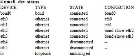
The output indicates the presence of two new interfaces by the name eth4 and eth5.
5. Load the team driver in the kernel with the modprobe command if it is not already loaded, and verify with the modinfo command:
|
# modprobe team |
|
|
# modinfo team |
|
|
filename: |
/lib/modules/3.10.0-123.el7.x86_64/kernel/drivers/net/team/team.ko |
|
alias: |
rtnl-link-team |
|
description: |
Ethernet team device driver |
|
author: |
Jiri Pirko <jpirko@redhat.com> |
|
license: |
GPL v2 |
|
srcversion: |
39F7B52A85A880B5099D411 |
|
depends: |
|
|
intree: |
Y |
|
vermagic: |
3.10.0-123.el7.x86_64 SMP mod_unload modversions |
|
signer: |
Red Hat Enterprise Linux kernel signing key |
|
sig_key: |
00:AA:5F:56:C5:87:BD:82:F2:F9:9D:64:BA:83:DD:1E:9E:0D:33:4A |
|
sig_hashalgo: |
sha256 |
|
…… . . |
|
6. Add a logical interface called team0 of type team with connection name team0, IP address 192.168.2.120/24, and gateway 192.168.2.1:
# nmcli con add type team con-name team0 ifname team0 ip4 192.168.2.120/24 \
gw4 192.168.2.1
Connection 'team0' (9d3e2053-e83f-49fb-98fb-1ec0ac57c260) successfully added.
This command has added a bond device and created ifcfg-team0 file in the /etc/sysconfig/network-scripts directory with all necessary directives.
7. Show the contents of the ifcfg-team0 file:
# cat /etc/sysconfig/network-scripts/ifcfg-team0
DEVICE=team0
DEVICETYPE=Team
BOOTPROTO=none
IPADDR0=192.168.2.120
PREFIX0=32
GATEWAY0=192.168.2.1
DEFROUTE=yes
IPV4_FAILURE_FATAL=no
IPV6INIT=yes
IPV6_AUTOCONF=yes
IPV6_DEFROUTE=yes
IPV6_PEERDNS=yes
IPV6_PEERROUTES=yes
IPV6_FAILURE_FATAL=no
NAME=team0
UUID=9d3e2053-e83f-49fb-98fb-1ec0ac57c260
ONBOOT=yes
8. Add eth4 and eth5 interfaces as slaves to the team:
# nmcli con add type team-slave con-name eth4 ifname eth4 master team0
Connection 'eth4' (22c69e0e-e185-464d-b1c0-784119490fd1) successfully added.
# nmcli con add type team-slave con-name eth5 ifname eth5 master team0
Connection 'eth5' (30557806-c821-4002-87d2-03df6483f675) successfully added.
This command has added eth4 and eth5 interfaces as slaves to team0, and has created ifcfg-eth4 and ifcfg-eth5 files in the /etc/sysconfig/network-scripts directory with all necessary directives.
9. Show the contents of the ifcfg-eth4 and ifcfg-eth5 files:
# cat /etc/sysconfig/network-scripts/ifcfg-eth4
BOOTPROTO=dhcp
DEFROUTE=yes
PEERDNS=yes
PEERROUTES=yes
IPV4_FAILURE_FATAL=no
IPV6INIT=yes
IPV6_AUTOCONF=yes
IPV6_DEFROUTE=yes
IPV6_PEERDNS=yes
IPV6_PEERROUTES=yes
IPV6_FAILURE_FATAL=no
NAME=eth4
UUID=22c69e0e-e185-464d-b1c0-784119490fd1
DEVICE=eth4
ONBOOT=yes
TEAM_MASTER=team0
DEVICETYPE=TeamPort
# cat /etc/sysconfig/network-scripts/ifcfg-eth5
BOOTPROTO=dhcp
DEFROUTE=yes
PEERDNS=yes
PEERROUTES=yes
IPV4_FAILURE_FATAL=no
IPV6INIT=yes
IPV6_AUTOCONF=yes
IPV6_DEFROUTE=yes
IPV6_PEERDNS=yes
IPV6_PEERROUTES=yes
IPV6_FAILURE_FATAL=no
NAME=eth5
UUID=30557806-c821-4002-87d2-03df6483f675
DEVICE=eth5
ONBOOT=yes
TEAM_MASTER=team0
DEVICETYPE=TeamPort
10. Activate team0:
# nmcli con up team0
Connection successfully activated (D-Bus active path: /org/freedesktop/NetworkManager/ActiveConnection/8)
11. Check the new connection and IP assignments:
# ip addr | grep team0
6: eth4: <BROADCAST,MULTICAST,UP,LOWER_UP> mtu 1500 qdisc pfifo_fast master team0 state UP qlen 1000
7: eth5: <BROADCAST,MULTICAST,UP,LOWER_UP> mtu 1500 qdisc pfifo_fast master team0 state UP qlen 1000
12: team0: <BROADCAST,MULTICAST,UP,LOWER_UP> mtu 1500 qdisc noqueue state UP
inet 192.168.2.120/24 brd 192.168.2.255 scope global team0
The output indicates the IP assigned to the team interface with all the interface devices up.
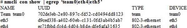
12. Show the connection information for the team and slaves:
13. Get the details of the team devices:
# teamnl team0 ports
7: eth5: up 0Mbit HD
6: eth4: up 0Mbit HD
14. Check the status of the team and the included interfaces:
# teamdctl team0 state
setup:
runner: activebackup
ports:
eth4
link watches:
link summary: up
instance[link_watch_0]:
name: ethtool
link: up
eth5
link watches:
link summary: up
instance[link_watch_0]:
name: ethtool
link: up
runner:
active port: eth5
15. Restart the system to confirm configuration persistence across reboots:
# reboot
16. Run steps 11 to 14 again to verify the team and IP assignments.
17. Open the hosts file and append the following entries to it:
# vi /etc/hosts
192.168.2.110 server1team.example.net server1team
192.168.2.120 server2team.example.net server2team
18. Copy this hosts file to server2 so that there are the same entries on both servers:
# scp /etc/hosts server2:/etc
19. Once the setup is complete, issue the ping command (with –c option to send three packets) to test connectivity with server1team:
# ping –c 3 server1team
PING server1team.example.com (192.168.2.110) 56(84) bytes of data.
64 bytes from server1team.example.com (192.168.2.110): icmp_seq=1 ttl=64 time=0.254 ms
64 bytes from server1team.example.com (192.168.2.110): icmp_seq=2 ttl=64 time=0.408 ms
64 bytes from server1team.example.com (192.168.2.110): icmp_seq=3 ttl=64 time=0.411 ms
--- server1team.example.com ping statistics ---
3 packets transmitted, 3 received, 0% packet loss, time 1999ms
rtt min/avg/max/mdev = 0.254/0.357/0.411/0.076 ms
Graphical Network Administration Tools for Configuring Bonding and Teaming
RHEL7 offers Network Settings and Network Connections tools for graphical management of network interfaces including the administration of bonding and teaming. The Network Settings (or Control Network) is located in the Control Center and it may be accessed by clicking the network icon at the top right-hand corner in the GNOME desktop or by clicking Applications | System Tools | Settings | Network. Figure 15-1 shows the window that appears when this tool is invoked on server1.
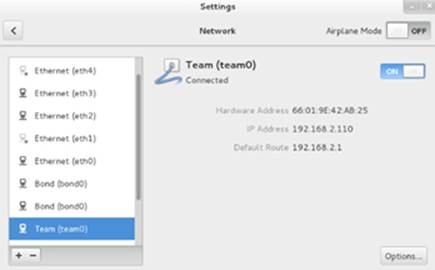
Figure 15-1 Network Settings Tool – Main Window
The Network Connections tool can be invoked by running the nm-connection-editor command in an X terminal window or by choosing Application | Sundry | Network Connections. Figure 15-2 shows the window that appears when this tool is brought up on server1.
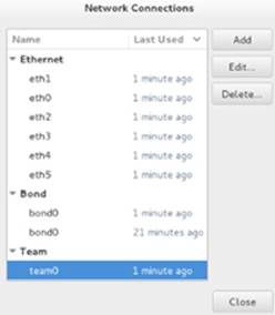
Figure 15-2 Network Connections Tool – Main Window
Both tools allow us to create new bonding and teaming connections, as well as modify the existing ones in addition to other interface management functions. To create a new connection, simply click the + sign in the bottom left corner on the Network Settings tool or the Add button in the Network Connections tool and select the type of connection to create. Once this is completed, both tools provide a common interface for configuration. Figure 15-3 shows the window that appears when “team” is selected as a connection type. It will be very similar for the bond connection type.
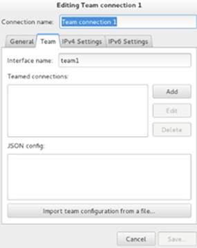
Figure 15-3 Add a Teaming Channel
We can assign a name of our choice to the connection in the space provided at the top. The four tabs—General, Team/Bond, IPv4 Settings, IPv6 Settings—allow us to configure a new channel. The tab Team (or Bond) lets us enter type-specific data; the rest of the tabs are associated with IP assignments, DNS, routing, and other general configuration items.
We can also use these tools to modify the settings of an existing team/bond connection. This can be done by highlighting a configured team/bond interface and then clicking Options (Network Settings) or Edit (Network Connections) on the main window of either tool.
IPv6
With the explosive growth of the Internet, the presence of an extremely large number of systems requiring an IP, and an ever-increasing demand for additional addresses, the conventional IPv4 address space, which provides approximately 4.3 billion addresses, has almost been exhausted. To meet the future demand, a new version of IP is now available and its use is on the rise. This new version is referred to as IPv6 (IP version 6). By default, IPv6 is enabled in RHEL7 for all configured standalone and logical interfaces, unless it is disabled manually.
IPv6 is a 128-bit software address providing access to 2128 addresses, which is approximately 340 undecillion (340 followed by 36 zeros) addresses. This is an extremely large space, and it is expected to fulfill the IP requirements for several decades to come.
Unlike IPv4 addresses, which are represented as four dot-separated octets, IPv6 addresses contain eight colon-separated groups of four hexadecimal numbers. A sample v6 IP would be 1204:bab1:21d1:bb43:23a1:9bde:87df:bac9. It looks a bit daunting at first sight; however, methods to simplify their representation do exist.
Below, the ip addr command output from server1 shows IPv6 addresses for configured interfaces:
# ip addr | grep inet6
inet6 ::1/128 scope host
inet6 fe80::5054:ff:fe17:918d/64 scope link
inet6 fe80::5054:ff:fe39:169a/64 scope link
inet6 fe80::5054:ff:fe47:30d7/64 scope link
inet6 fe80::5054:ff:fe6d:d236/64 scope link
It shows five IPv6 addresses. The first one belongs to the loopback interface, and the following IPv6 addresses are assigned to eth0, eth1, team0, and bond0 interfaces, respectively.
Managing IPv6
IPv6 can be assigned to interfaces using any of the network management tools available to us. The ip command, the NetworkManager tools, the Network Settings tool, and the Network Connections tool all have the ability to configure interfaces with IPv6 assignments. Entries added with the ipcommand do not survive system reboots; however, those added with the other mentioned tools stay persistent, as they are stored in interface configuration files in the /etc/sysconfig/network-scripts directory. Alternatively, we can directly add or modify entries in these files as required. The next exercise will demonstrate how to add IPv6 addresses manually by directly editing interface configuration files.
EXAM TIP: Both IPv4 and IPv6 addresses can be assigned to a single network interface port and they should work without any conflicts.
For using the GUI tools for IPv6 assignments, refer to Figure 15-3 (tab IPv6 Settings) in the previous section. For using the NetworkManager CLI for this purpose, refer to Chapter 12 “Administering Network Interfaces and Network Clients”.
Exercise 15-5: Configure and Test IPv6 Addresses
This exercise should be done on server1 and server2.
In Chapter 12, “Administering Network Interfaces and Network Clients”, we configured eth1 interface on both server1 and server2 with IPv4 addresses 192.168.0.111 and 192.168.0.121, respectively. In this exercise, you will edit their interface configuration files on both systems and assign static IPv6 addresses. You will assign them hostnames server1ipv6.example.com and server2ipv6.example.com with aliases server1ipv6 and server2ipv6, respectively. You will add IPv6 and hostname mapping to the hosts table. You will reboot the systems to verify configuration persistence. Finally, you will run a ping test from server1ipv4 to server2ipv4 and another from server2ipv6 to server1ipv6 to confirm IPv4 and IPv6 connectivity. You will also attempt to ssh into server2ipv6 from server1ipv6.
1. Log on to server1 and server2 in separate windows and run the following command to determine IPv6 status:
[server1]# ip addr show eth1
3: eth1: <BROADCAST,MULTICAST,UP,LOWER_UP> mtu 1500 qdisc pfifo_fast state UP qlen 1000
link/ether 52:54:00:39:16:9a brd ff:ff:ff:ff:ff:ff
inet 192.168.0.111/24 brd 192.168.0.255 scope global eth1
valid_lft forever preferred_lft forever
inet6 fe80::5054:ff:fe39:169a/64 scope link
valid_lft forever preferred_lft forever
[server2]# ip addr show eth1
3: eth1: <BROADCAST,MULTICAST,UP,LOWER_UP> mtu 1500 qdisc pfifo_fast state UP qlen 1000
link/ether 52:54:00:96:13:58 brd ff:ff:ff:ff:ff:ff
inet 192.168.0.121/24 brd 192.168.0.255 scope global eth1
valid_lft forever preferred_lft forever
inet6 fe80::5054:ff:fe96:1358/64 scope link
valid_lft forever preferred_lft forever
The output indicates the assignment of static IPv4 addresses and DHCP-generated IPv6 addresses.
2. Open the interface configuration file ifcfg-eth1 in the /etc/sysconfig/network-scripts directory on both servers and ensure they contain the following lines:
[server1]
IPV6INIT=yes
IPV6ADDR=2602:306:cc2d:f591::A/64
IPV6_DEFAULTGW=2602:306:cc2d:f591::1
[server2]
IPV6INIT=yes
IPV6ADDR=2602:306:cc2d:f591::B/64
IPV6_DEFAULTGW=2602:306:cc2d:f591::1
The IPV6INIT directive enables the IPv6 support for the (eth1) interface and the IPV6ADDR and IPV6_DEFAULTGW directives set the specified IPv6 address and default gateway.
3. Open the hosts table on both servers and append the following:
2602:306:cc2d:f591::A server1ipv6.example.com server1ipv6
2602:306:cc2d:f591::B server2ipv6.example.com server2ipv6
4. Deactivate and reactivate eth1 interface on both servers so that the new IPv6 assignments take effect along with the existing IPv4 addresses:
[server1]# ifdown eth1 ; ifup eth1
Connection successfully activated (D-Bus active path: /org/freedesktop/NetworkManager/ActiveConnection/12)
[server2]# ifdown eth1 ; ifup eth1
Connection successfully activated (D-Bus active path: /org/freedesktop/NetworkManager/ActiveConnection/12)
5. Reboot both systems:
# reboot
6. Check that IPv4 and IPv6 assignments are there on both servers:
[server1]# ip addr show eth1
3: eth1: <BROADCAST,MULTICAST,UP,LOWER_UP> mtu 1500 qdisc pfifo_fast state UP qlen 1000
link/ether 52:54:00:39:16:9a brd ff:ff:ff:ff:ff:ff
inet 192.168.0.111/24 brd 192.168.0.255 scope global eth1
valid_lft forever preferred_lft forever
inet6 2602:306:cc2d:f591::a/64 scope global
valid_lft forever preferred_lft forever
inet6 fe80::5054:ff:fe39:169a/64 scope link
valid_lft forever preferred_lft forever
[server2]# ip addr show eth1
3: eth1: <BROADCAST,MULTICAST,UP,LOWER_UP> mtu 1500 qdisc pfifo_fast state UP qlen 1000
link/ether 52:54:00:96:13:58 brd ff:ff:ff:ff:ff:ff
inet 192.168.0.121/24 brd 192.168.0.255 scope global eth1
valid_lft forever preferred_lft forever
inet6 2602:306:cc2d:f591::b/64 scope global
valid_lft forever preferred_lft forever
inet6 fe80::5054:ff:fe96:1358/64 scope link
valid_lft forever preferred_lft forever
7. Perform two connectivity tests—one for IPv4 from server1ipv4 to server2ipv4 and the second for IPv6 from server1ipv6 to server2ipv6:
[server1]# ping –c 2 server2ipv4
PING server2ipv4.example.com (192.168.0.121) 56(84) bytes of data.
64 bytes from server2ipv4.example.com (192.168.0.121): icmp_seq=1 ttl=64 time=0.402 ms
64 bytes from server2ipv4.example.com (192.168.0.121): icmp_seq=2 ttl=64 time=0.394 ms
--- server2ipv4.example.com ping statistics ---
2 packets transmitted, 2 received, 0% packet loss, time 1000ms
rtt min/avg/max/mdev = 0.394/0.398/0.402/0.004 ms
[server1]# ping6 –c 2 server2ipv6
PING server2ipv6(server2ipv6.example.com) 56 data bytes
64 bytes from server2ipv6.example.com: icmp_seq=1 ttl=64 time=0.084 ms
64 bytes from server2ipv6.example.com: icmp_seq=2 ttl=64 time=0.072 ms
--- server2ipv6 ping statistics ---
2 packets transmitted, 2 received, 0% packet loss, time 1000ms
rtt min/avg/max/mdev = 0.072/0.078/0.084/0.006 ms
The above tests show that the two servers have both IPv4 as well as IPv6 assignments configured on one of their Ethernet interfaces, and that both are functioning without any issues.
8. Test ssh access from server2ipv6 to server1ipv6:
[server1]# ssh server1ipv6
The authenticity of host 'server1ipv6 (2602:306:cc2d:f591::a)' can't be established.
ECDSA key fingerprint is 9b:c6:eb:6e:46:ee:17:4d:71:3d:0f:93:1c:19:a8:5b.
Are you sure you want to continue connecting (yes/no)? yes
Warning: Permanently added 'server1ipv6,2602:306:cc2d:f591::a' (ECDSA) to the list of known hosts.
root@server1ipv6's password:
Last login: Tue Dec 16 14:53:14 2014 from 192.168.0.13
[root@server1 ∼]#
Both successful testings validate the IPv4 and IPv6 assignments.
Though the use of IPv6 is growing fast and its support is available in RHEL7 by default, our focus will still be on IPv4 in this book. We will continue to use the term IP to represent IPv4 protocol, unless stated otherwise.
Routing
Routing is the process of choosing paths on the network along which to send network traffic. This process is implemented with the deployment of specialized and sophisticated hardware devices called routers. Routers are widely used on the Internet and in corporate networks for this purpose. A RHEL system may also be configured to route traffic to other networks; however, that capability will be not as sophisticated.
When systems on two distinct networks communicate with each other, proper routes must be in place for them to be able to talk. For instance, if a system on network A sends a data packet to a system on network B, one or more routing devices is involved to route the packet to the correct destination network. The two networks can be located in a close proximity or across continents. Once the data packet reaches a router, the router selects the next router along the path toward the destination node. The packet passes from one router to another until it reaches the router that is able to deliver the packet directly to the destination system. Each router along the path is referred to as a hop. Most advanced routers have the ability to construct their routing tables automatically and intelligently to bypass network failures and congestions. There are many protocols used for routing purposes. However, the Routing Information Protocol (RIP) and the Open Shortest Path First (OSPF) are more common and widely employed.
One of three rules is applied in the routing mechanism to determine the correct route:
· If the source and destination systems are on the same network, the packet is sent directly to the destination system.
· If the source and destination systems are on two different networks, all defined (static or dynamic) routes are tried one after the other. If a proper route is determined, the packet is forwarded to it, which then forwards the packet to the correct destination.
· If the source and destination systems are on two different networks but no routes are defined between them, the packet is forwarded to the default router (or the default gateway), which attempts to search for an appropriate route to the destination. If found, the packet is delivered to the destination system.
Routing Table
A routing table preserves information about available routes and their status. It may be built and updated dynamically or manually by adding or removing routes. The ip command can be used to view entries in the routing table on our RHEL7 system:
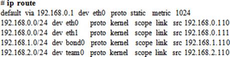
The output is organized in multiple columns that are explained in Table 15-2:
|
Column |
Description |
|
Network destination |
Displays the address and netmask of the destination network. The keyword default identifies the IP address of the default gateway for sending out traffic to other networks in the absence of a proper route. |
|
dev |
Name of the physical or virtual network interface to be used to send out traffic. |
|
proto |
Identifies the routing protocol as defined in the /etc/iproute2/rt_protos file. The proto kernel implies that the route was installed by the kernel during auto-configuration. The proto static means that the route was installed by you to override dynamic routing. |
|
scope |
Determines the scope of the destination as defined in the /etc/iproute2/rt_scopes file. Values may be global, nowhere, host, or link. |
|
src |
Shows the source address associated with the interface for sending data out to the destination. |
|
metric |
Displays the cost of using a route, which is usually the number of hops to the destination system. Systems on the local network are one hop, and each subsequent router thereafter is an additional hop. |
Table 15-2 Routing Table
Some other commands, such as route, will display additional columns of information that include flags, references, use, and iface. Common flag values are U (route is up), H (destination is a host), G (route is a gateway); references are not used in Linux; use indicates the count of lookups for the route; and iface shows the network interface to be used for sending data packets out.
Managing Routes
Managing routes involves adding, modifying, or deleting routes, and setting the default route. The ip command, the NetworkManager TUI and CLI tools, the Network Settings GUI, or the Network Connections GUI can be used for route administration. Entries added with the ip command do not survive system reboots; however, those added with the other mentioned tools stay persistent, as they are saved in interface specific route-* files (route-eth1, route-bond0, route-team0, and so on) in the /etc/sysconfig/network-scripts directory. Alternatively, we can directly create or modify these files as desired. The next exercise will demonstrate how to add static routes manually with the ip command first and then add the entries to appropriate route configuration files for persistence. The GUI tools have the Routes option available when IPv4 or IPv6 Settings is selected as illustrated in Figure 15-3 earlier in this chapter.
Exercise 15-6: Add Static Routes Manually
This exercise should be done on server1.
In this exercise, you will temporarily add a static route to network 192.168.3.0/24 via eth1 with gateway 192.168.0.1 and another one to network 192.168.4.0/24 via team0 with gateway 192.168.2.1 using the ip command. You will reboot the system and check for their availability. You will permanently re-add the routes by creating files in the /etc/sysconfig/network-scripts directory and adding entries. You will reboot the system to confirm their persistence. Finally, you will delete both routes.
1. Add a static route to 192.168.3.0/24 via eth1 with gateway 192.168.0.1:
# ip route add 192.168.3.0/24 via 192.168.0.1 dev eth1
2. Add a static route to 192.168.4.0/24 via team0 with gateway 192.168.2.1:
# ip route add 192.168.4.0/24 via 192.168.2.1 dev team0
3. Show the routing table to validate the addition of the new routes:
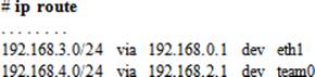
4. Reboot the system and run ip route again to confirm the removal of the new routes.
5. Create files route-eth1 and route-team0 in /etc/sysconfig/network-scripts and insert the following entries:
# cd /etc/sysconfig/network-scripts
# vi route-eth1
ADDRESS0=192.168.3.0
NETMASK0=255.255.255.0
GATEWAY0=192.168.0.1
# vi route-team0
ADDRESS0=192.168.4.0
NETMASK0=255.255.255.0
GATEWAY0=192.168.2.1
6. Restart eth1 and team0 interfaces for the routes to take effect:
# ifdown eth1 ; ifup eth1
# ifdown team0 ; ifup team0
7. Run the ip route command again to validate the presence of the new routes.
8. Delete both routes by removing their entries from the routing table and deleting the route configuration files:
# ip route del 192.168.3.0/24
# ip route del 192.168.4.0/24
# rm –f route-eth1 route-team0
9. Confirm the deletion:
# ip route
You should not see the routes.
Chapter Summary
This chapter began with an overview of the concept of link aggregation, and continued with presenting its benefits and various implementation methods. We looked at interface bonding and teaming, and performed several exercises to demonstrate how to set them up by hand-editing configuration files and using the NetworkManager CLI. We also provided an overview of the graphical network management tools for configuring bonding and teaming. We tested the connections between the two RHEL7 servers to validate their functionality.
We then looked at Internet Protocol version 6, the use of which is on the rise. We reviewed the basics of IPv6 and configured it on both servers. This configuration was performed to demonstrate how both IPv4 and IPv6 addresses could co-exist on the same interface. We tested successful configuration by sending test packets.
The last topic of this chapter discussed routing. Routing is vital in the sense that it provides the backbone for transferring IP traffic among networks over public and private networks. We looked at the function of a routing table and saw how to view table entries. Lastly, we added new routes using commands and by editing interface-specific route configuration files.
Chapter Review Questions
1. Bonding supports IPv4 as well as IPv6, while teaming does not. True or False?
2. What is the function of the default gateway?
3. Which command is used to display the hardware address of a network interface?
4. Which directory is used to store the interface configuration files?
5. What is the purpose of the ONBOOT directive in the interface configuration file?
6. Name two implementations of link aggregation in RHEL7.
7. The /etc/hosts file maintains the hostname to hardware address mappings. True or False?
8. What does the ip addr command produce?
9. Which link aggregation method is implemented in both kernel space and userland?
10. It is not possible to configure an IPv6 address on an interface that is already using an IPv4 address. True or False?
11. Which command can be run at the command prompt in an X terminal window to bring up the graphical Network Connections tool?
Answers to Chapter Review Questions
1. False. Both bonding and teaming support IPv4 as well as IPv6.
2. The default gateway is used in the absence of usable routes to a destination.
3. The ip command.
4. The /etc/sysconfig/network-scripts directory.
5. The value of this directive determines whether to activate this interface at system boot.
6. The two implementations for link aggregation in RHEL7 are teaming and bonding.
7. False. This file maintains IP to hostname mappings.
8. This command displays IP assignments, hardware address, and other data for network interfaces.
9. Teaming is implemented in both user and kernel spaces.
10. False. An interface can have both IPv4 and IPv6 addresses assigned, and working.
11. The command to bring up the graphical Network Connections tool is nm-connection-editor.
DIY Challenge Labs
The following labs are useful to strengthen most of the concepts and topics learned in this chapter. It is expected that you perform these labs without any additional help. A step-by-step guide is not provided, as the implementation of these labs requires the knowledge that has been presented in this chapter. Use defaults or your own thinking for missing information.
Lab 15-1: Set Up Teaming between Two Systems Using NetworkManager TUI
Present a pair of network interfaces to each server and configure them as a team on both servers. Assign them IPv4 addresses on 192.168.1.0/24 network and use any hostnames. Execute ping tests to confirm operational health. Ensure the configuration survives system reboots. Use configuration at will where missing.
Lab 15-2: Set Up Bonding between Two Systems Using NetworkManager TUI
Present a pair of network interfaces to each server and configure them as a bond on both servers. Assign them any IPv6 addresses and hostnames. Execute ping6 tests to confirm operational health. Ensure the configuration survives system reboots. Use configuration at will where missing.
Lab 15-3: Configure Static Routes
Configure a persistent static route to 192.168.5.0/24 network on one system and attach it to the team interface created in Lab 15-1. Configure another persistent static route to 192.168.5.0/24 network on the other system and attach it to the bond interface created in Lab 15-2. Ensure the configuration survives system reboots. Use configuration at will where missing.
All materials on the site are licensed Creative Commons Attribution-Sharealike 3.0 Unported CC BY-SA 3.0 & GNU Free Documentation License (GFDL)
If you are the copyright holder of any material contained on our site and intend to remove it, please contact our site administrator for approval.
© 2016-2026 All site design rights belong to S.Y.A.