Windows Internals, Sixth Edition, Part 1 (2012)
Chapter 7. Networking
Microsoft Windows was designed with networking in mind, and it includes broad networking support that is integrated with the I/O system and the Windows APIs. The four basic types of network software components are services, APIs, protocols, and drivers for network adapters—with each component layered on top of the next to form a network stack. Windows has well-defined interfaces for each layer, so in addition to using the wide variety of APIs, protocols, and network adapter device drivers that ship with Windows, third parties can extend the operating system’s networking capabilities by developing their own components.
In this chapter, we take you from the top of the Windows networking stack to the bottom. First, we present the mapping between the Windows networking software components and the Open Systems Interconnection (OSI) reference model. Then we briefly describe the networking APIs available on Windows and explain how they are implemented. You’ll learn how multiple redirector support and name resolution work, see how to access and cache remote files, and learn how a multitude of drivers interact to form a network protocol stack. After looking at the implementation of network adapter device drivers, we examine binding, which is the glue that connects services, protocol stacks, and network adapters.
Windows Networking Architecture
The goal of network software is to take a request (in the form of an I/O request) from an application on one machine, pass it to another machine, execute the request on the remote machine, and return the results to the first machine. In the course of this process, the request must be transformed several times. A high-level request, such as “read x number of bytes from file y on machine z,” requires software that can determine how to get to machine z and what communication software that machine understands. Then the request must be altered for transmission across a network—for example, divided into short packets of information. When the request reaches the other side, it must be checked for completeness, decoded, and sent to the correct operating system component for execution. Finally, the reply must be encoded for sending back across the network.
The OSI Reference Model
To help different computer manufacturers standardize and integrate their networking software, in 1984 the International Organization for Standardization (ISO) defined a software model for sending messages between machines. The result was the Open Systems Interconnection (OSI)reference model. The model defines six layers of software and one physical layer of hardware, as shown in Figure 7-1.
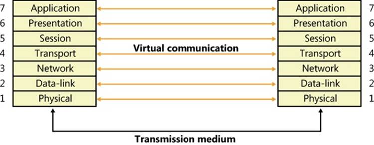
Figure 7-1. OSI reference model
The OSI reference model is an idealized scheme that few systems implement precisely, but it’s often used to frame discussions of networking principles. Each layer on one machine assumes that it is “talking to” the same layer on the other machine. Both machines “speak” the same language, or protocol, at the same level. In reality, however, a network transmission must pass down each layer on the client machine, be transmitted across the network, and then pass up the layers on the destination machine until it reaches a layer that can understand and implement the request.
The purpose of each layer in the OSI model is to provide services to higher layers and to abstract how the services are implemented at lower layers. Describing the details of each layer is beyond the scope of this book, but following is a brief description of each layer in the OSI model.
NOTE
Most network descriptions start with the top-most layer and work down to the lowest layer; however, here the description of the layers will start at the bottom and work toward the top, to demonstrate how each layer builds upon the services provided by the layer beneath it.
§ Physical. This is the lowest layer in the OSI model, and it exchanges signals between cooperating network entities over some physical medium (wire, radio, fiber, or other type). The physical layer specifies the mechanical, electrical, functional, and procedural standards for accessing the medium, such as connectors, cabling, signaling, and so on. Common examples are Ethernet (IEEE 802.3) and Wi-Fi (IEEE 802.11).
§ Datalink. This layer exchanges data frames (also called packets) between physically adjacent network entities (known as stations) using the services provided by the physical layer. By its nature, the datalink layer is tightly tied to the physical layer and is really more of an architectural abstraction than the other layers within the model. The datalink layer provides each station with its own unique address on the network, and it provides point-to-point communications between stations (such as between two systems connected to the same Ethernet). The capabilities of the datalink layer vary considerably, depending upon the physical layer. Typically, transmit and receive errors are detected by the datalink layer, and in some instances, the error might be corrected. A datalink layer can be connection oriented, which is typically used in wide area networks (WANs), or connectionless, which is typically used in local area networks (LANs). The IEEE (Institute of Electrical and Electronics Engineers) 802 committee is responsible for the majority of the LAN architectures used throughout the world, and they specify the physical and datalink layers of most networking equipment. They divide the datalink layer into two sublayers: the Logical Link Control (LLC) and the Medium Access Control (MAC). The LLC layer provides a single access method for the network layer to communicate with any 802.x MAC, insulating the network layer from the physical LAN type. The MAC layer provides access-control functions to the shared network medium, and it specifies signaling, the sharing protocol, address recognition, frame generation, CRC generation, and so on. The datalink layer does not guarantee that frames will be delivered to their destination.
§ Network. The network layer implements node addresses and routing functions to allow packets to traverse multiple datalinks. This layer understands the network topology (hiding it from the transport layer) and knows how to direct packets to the nearest router. Any network entity containing the network, datalink, and physical layers is considered to be a node, and the network layer can transfer data between any two nodes on the network. There are two types of nodes implemented by the network layer: end nodes, which are the source or destination of data, and intermediate nodes (usually referred to as routers), which route packets between end nodes. Network-layer service can be either connection oriented, where all packets traveling between the end nodes follow the same path through the network, or connectionless, where each packet is routed independently. The network layer does not guarantee that packets will be delivered to their destination.
§ Transport. The transport layer provides a transparent data-transfer mechanism between end nodes. On the sending side, the transport layer receives an unstructured stream of data from the layer above and segments the data into discrete packets, which can be sent across the network, using the services of the network layer beneath it. On the receiving side, the transport layer reassembles the packets received from the network layer into a stream of data and provides it to the layer above. This layer provides reliable data transfer and will re-transmit lost or corrupted packets to ensure that the data stream received is identical to the data stream that was sent.
§ Session. This layer implements a connection or pipe between cooperating applications. Each connection endpoint has its own address (often called a port), which is unique on that system. There are a variety of communications services provided by session layers, such as two-way simultaneous (full-duplex), two-way alternate (single-duplex), or one-way. Once a connection is established, the systems typically send periodic messages to each other to ensure that each end of the connection is functioning. If an uncorrectable transmission error is detected over a connection, the connection is typically terminated and disconnected.
§ Presentation. The presentation layer is responsible for preserving the information content of data sent over the network. It handles data formatting, including issues such as whether lines end in a carriage return/line feed (CR/LF) or just a carriage return (CR), whether data is to be compressed or encrypted, converting binary data from little-endian to big-endian, and so on. This layer is not present in most network protocol stacks, so its functionality is implemented at the application layer.
§ Application. This is a layer that handles the information transfer between two network applications, including functions such as security checks, identification of the participating machines, and initiation of the data exchange. This is the protocol that is used by two communicating applications, and is application specific.
The gray lines in Figure 7-1 represent protocols used in transmitting a request to a remote machine. As stated earlier, each layer of the hierarchy assumes that it is speaking to the same layer on another machine and uses a common protocol. The collection of protocols through which a request passes on its way down and back up the layers of the network is called a protocol stack.
Not all network protocol suites implement all the layers in the OSI model. (The presentation layer is rarely provided.) In particular, the TCP/IP protocol stack (which predates the OSI model) matches poorly to the abstractions of OSI. As data travels down the network stack, each layer adds a header (and possibly a trailer) to the data payload, building up a structure that is very similar to the layers of an onion. When this structure is received on a remote node, it travels up the network stack, with each layer stripping off its header (and trailer) until the data payload is delivered to the receiving application.
Windows Networking Components
Figure 7-2 provides an overview of the components of Windows networking, showing how each component fits into the OSI reference model and which protocols are used between layers. The mapping between OSI layers and networking components isn’t precise, which is the reason that some components cross layers. The various components include the following:
§ Networking APIs provide a protocol-independent way for applications to communicate across a network. Networking APIs can be implemented in user mode or in both user mode and kernel mode. In some cases, they are wrappers around another networking API that implements a specific programming model or provides additional services. (Note that the term networking API also describes any programming interfaces provided by networking-related software.)
§ Transport Driver Interface (TDI) clients are legacy kernel-mode device drivers that usually implement the kernel-mode portion of a networking API’s implementation. TDI clients get their name from the fact that the I/O request packets (IRPs) they send to protocol drivers are formatted according to the Windows Transport Driver Interface standard (documented in the Windows Driver Kit). This standard specifies a common programming interface for kernel-mode device drivers. (See Chapter 8, “I/O System,” in Part 2 for more information about IRPs.) The TDI interface is deprecated and will be removed in a future version of Windows. The TDI interface is now being exported by the TDI Extension (TDX) Driver. Kernel-mode network clients should now use the Winsock Kernel (WSK) interface for accessing the network stack.
§ TDI transports (also known as transports) and Network Driver Interface Specification (NDIS) protocol drivers (or protocol drivers) are kernel-mode network protocol drivers. They accept IRPs from TDI clients and process the requests these IRPs represent. This processing might require network communications with a peer, prompting the TDI transport to add protocol-specific headers (for example, TCP, UDP, and/or IP) to data passed in the IRP, and to communicate with adapter drivers using NDIS functions (also documented in the Windows Driver Kit). TDI transports generally facilitate application network communications by transparently performing message operations such as segmentation and reassembly, sequencing, acknowledgment, and retransmission.
§ Microsoft has decided that TCP/IP has won the network protocol wars, so it has re-architected the network protocol portion of the network stack from being protocol-neutral to being TCP/IP-centric. The interface between the TCP/IP protocol driver and Winsock is known as theTransport Layer Network Provider Interface (TLNPI) and is currently undocumented.
§ Winsock Kernel (WSK) is a transport-independent, kernel-mode networking API that replaces the legacy TDI. WSK provides network communication by using socket-like programming semantics similar to user-mode Winsock, while also providing unique features such as asynchronous I/O operations built on IRPs and event callbacks. WSK also natively supports IP version 6 (IPv6) functionality in the Next Generation TCP/IP network stack in Windows.
§ The Windows Filtering Platform (WFP) is a set of APIs and system services that provide the ability to create network filtering applications. The WFP allows applications to interact with packet processing at different levels of the Windows networking stack, much like file system filters. Similarly, network data can be traced, filtered, and also modified before it reaches its destination.
§ WFP callout drivers are kernel-mode drivers that implement one or more callouts, which extend the capabilities of the WFP by processing TCP/IP-based network data in ways that extend the basic functionality provided by the WFP.
§ The NDIS library (Ndis.sys) provides an abstraction mechanism that encapsulates Network Interface Card (NIC) drivers (also known as NDIS miniports), hiding from them the specifics of the Windows kernel-mode environment. The NDIS library exports functions for use by TCP/IP and legacy TDI transports.
§ NDIS miniport drivers are kernel-mode drivers that are responsible for interfacing the network stack to a particular NIC. NDIS miniport drivers are written so that they are wrapped by the Windows NDIS library. NDIS miniport drivers don’t process IRPs; rather, they register a call-table interface to the NDIS library that contains pointers to functions that perform simple operations on the NIC, such as sending a packet or querying properties. NDIS miniport drivers communicate with network adapters by using NDIS library functions that resolve to hardware abstraction layer (HAL) functions.
As Figure 7-2 shows, the OSI layers don’t correspond to actual software. WSK transport providers, for example, frequently cross several boundaries. In fact, the bottom three layers of software and the hardware layer are often referred to collectively as the transport. Software components residing in the upper three layers are referred to as users or clients of the transport.”
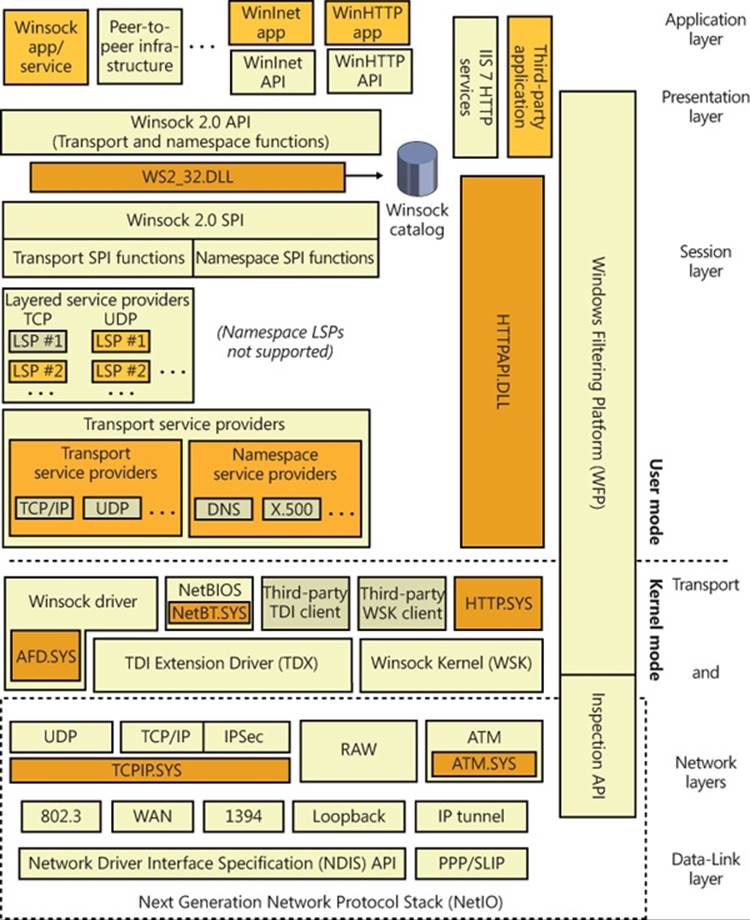
Figure 7-2. OSI model and Windows networking components
In the remainder of this chapter, we’ll examine the networking components shown in Figure 7-2 (as well as others not shown in the figure), looking at how they fit together and how they relate to Windows as a whole.
Networking APIs
Windows implements multiple networking APIs to provide support for legacy applications and compatibility with industry standards. In this section, we’ll briefly look at the networking APIs and describe how applications use them. Keep in mind that the decision about which API an application uses depends on characteristics of the API, such as which protocols the API can layer over, whether the API supports reliable (or bidirectional) communication, and the API’s portability to other Windows platforms the application might run on. We’ll discuss the following networking APIs:
§ Windows Sockets (Winsock)
§ Winsock Kernel (WSK)
§ Remote procedure call (RPC)
§ Web access APIs
§ Named pipes and mailslots
§ NetBIOS
§ Other networking APIs
Windows Sockets
The original Windows Sockets (Winsock) (version 1.0) was Microsoft’s implementation of BSD (Berkeley Software Distribution) Sockets, a programming API that became the standard by which UNIX systems have communicated over the Internet since the 1980s. Support for sockets on Windows makes the task of porting UNIX networking applications to Windows relatively straightforward. The modern versions of Winsock include most of the functionality of BSD Sockets but also include Microsoft-specific enhancements, which continue to evolve. Winsock supports reliable, connection-oriented communication as well as unreliable, connectionless communication. (“Reliable,” in this sense, indicates whether the sender is notified of any problems in the delivery of data to the receiver.) Windows provides Winsock 2.2, which adds numerous features beyond the BSD Sockets specification, such as functions that take advantage of Windows asynchronous I/O, to offer far better performance and scalability than straight BSD Sockets programming.
Winsock includes the following features:
§ Support for scatter-gather and asynchronous application I/O.
§ Quality of Service (QoS) conventions so that applications can negotiate latency and bandwidth requirements when the underlying network supports QoS.
§ Extensibility so that Winsock can be used with third-party protocols (deprecated).
§ Support for integrated namespaces with third-party namespace providers. A server can publish its name in Active Directory, for example, and by using namespace extensions, a client can look up the server’s address in Active Directory.
§ Support for multicast messages, where messages transmit from a single source to multiple receivers.
We’ll examine typical Winsock operation and then describe ways that Winsock can be extended.
Winsock Client Operation
The first step a Winsock application takes is to initialize the Winsock API with a call to an initialization function. A Winsock application’s next step is to create a socket that will represent a communications endpoint. The application obtains the address of the server to which it wants to connect by calling getaddrinfo (and later calling freeaddrinfo to release the information). The getaddrinfo function returns the list of protocol-specific addresses assigned to the server, and the client attempts to connect to each one in turn until it is able to establish a connection with one of them. This ensures that a client that supports both IP version 4 (IPv4) and IPv6 will connect to the appropriate and/or most efficient address on a server that might have both IPv4 and IPv6 addresses assigned to it. (IPv6 is preferred over IPv4.) Winsock is a protocol-independent API, so an address can be specified for any protocol installed on the system over which Winsock operates. After obtaining the server address, a connection-oriented client attempts to connect to the server by using connect and specifying the server address.
When a connection is established, the client can send and receive data over its socket using the recv and send APIs. A connectionless client specifies the remote address with connectionless APIs, such as the connectionless equivalents of send and recv, and sendto and recvfrom. Clients can also use the select and WSAPoll APIs to wait on or poll multiple sockets for synchronous I/O operations, or to check their state.
Winsock Server Operation
The sequence of steps for a server application differs from that of a client. After initializing the Winsock API, the server creates a socket and then binds it to a local address by using bind. Again, the address family specified—whether it’s TCP/IPv4, TCP/IPv6, or some other address family—is up to the server application.
If the server is connection oriented, it performs a listen operation on the socket, indicating the backlog, or the number of connections the server asks Winsock to hold until the server is able to accept them. Then it performs an accept operation to allow a client to connect to the socket. If there is a pending connection request, the accept call completes immediately; otherwise, it completes when a connection request arrives. When a connection is made, the accept function returns a new socket that represents the server’s end of the connection. (The original socket used for listening is not used for communications, only for receiving connection requests.) The server can perform receive and send operations by using functions such as recv and send. Like Winsock clients, servers can use the select and WSAPoll functions to query the state of one or more sockets; however, the Winsock WSAEventSelect function and overlapped (asynchronous) I/O extensions are preferred for better scalability. Figure 7-3 shows connection-oriented communication between a Winsock client and server.
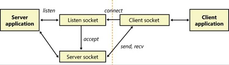
Figure 7-3. Connection-oriented Winsock operation
After binding an address, a connectionless server is no different from a connectionless client: it can send and receive data over the socket simply by specifying the remote address with each operation. Most connectionless protocols are unreliable and, in general, will not know whether the destination actually received the sent data packets (which are known as datagrams). Datagram protocols are ideal for quick message passing, where the overhead of establishing a connection is too much and reliability is not required (although an application can build reliability on top of the protocol).
Winsock Extensions
In addition to supporting functions that correspond directly to those implemented in BSD Sockets, Microsoft has added a handful of functions that aren’t part of the BSD standard. Two of these functions, AcceptEx (the Ex suffix is short for Extended) and TransmitFile, are worth describing because many Web servers on Windows use them to achieve high performance. AcceptEx is a version of the accept function that, in the process of establishing a connection with a client, returns the client’s address and the client’s first message. AcceptEx allows the server application to queue multiple accept operations so that high volumes of incoming connection requests can be handled. With this function, a web server avoids executing multiple Winsock functions that would otherwise be required.
After establishing a connection with a client, a web server frequently sends a file, such as a web page, to the client. The TransmitFile function’s implementation is integrated with the Windows cache manager so that a file can be sent directly from the file system cache. Sending data in this way is called zero-copy because the server doesn’t have to read the file data to send it; it simply specifies a handle to a file and the byte range (offset and length) of the file to send. In addition, TransmitFile allows a server to add prefix or suffix data to the file’s data so that the server can send header information, trailer information, or both, which might include the name of the web server and a field that indicates to the client the size of the message the server is sending. Internet Information Services (IIS), which is included with Windows, uses bothAcceptEx and TransmitFile to achieve better performance.
Windows also supports a handful of other multifunction APIs, including ConnectEx, DisconnectEx, and TransmitPackets. ConnectEx establishes a connection and sends the first message on the connection. DisconnectEx closes a connection and allows the socket handle representing the connection to be reused in a call to AcceptEx or ConnectEx. Finally, TransmitPackets is similar to TransmitFile, except that it allows for the sending of in-memory data in addition to, or in lieu of, file data. Finally, by using the WSAImpersonateSocketPeer andWSARevertImpersonation functions, Winsock servers can perform impersonation (described in Chapter 6) to perform authorization or to gain access to resources based on the client’s security credentials.
Extending Winsock
Winsock is an extensible API on Windows because third parties can add a transport service provider that interfaces Winsock with other protocols, or layers on top of existing protocols, to provide functionality such as proxying. Third parties can also add a namespace service providerto augment Winsock’s name-resolution facilities. Service providers plug in to Winsock by using the Winsock service provider interface (SPI). When a transport service provider is registered with Winsock, Winsock uses the transport service provider to implement socket functions, such as connect and accept, for the address types that the provider indicates it implements. There are no restrictions on how the transport service provider implements the functions, but the implementation usually involves communicating with a transport driver in kernel mode.
NOTE
Layered service providers are not secure and can be bypassed; secure network protocol layering must be done in kernel mode. Installing itself as a Winsock layered service provider (LSP) is a technique used frequently by malware and spyware.
A requirement of any Winsock client/server application is for the server to make its address available to clients so that the clients can connect to the server. Standard services that execute on the TCP/IP protocol use well-known addresses to make their addresses available. As long as a browser knows the name of the computer a Web server is running on, it can connect to the web server by specifying the well-known web server address (the IP address of the server concatenated with :80, the port number used for HTTP). Namespace service providers make it possible for servers to register their presence in other ways. For example, one namespace service provider might on the server side register the server’s address in Active Directory and on the client side look up the server’s address in Active Directory. Namespace service providers supply this functionality to Winsock by implementing standard Winsock name-resolution functions such as getaddrinfo and getnameinfo.
EXPERIMENT: LOOKING AT WINSOCK SERVICE AND NAMESPACE PROVIDERS
The Network Shell (Netsh.exe) utility included with Windows is able to show the registered Winsock transport and namespace providers by using the netsh winsock show catalog command. For example, if there are two TCP/IP transport service providers, the first one listed is the default provider for Winsock applications using the TCP/IP protocol. Here’s sample output from Netsh showing the registered transport service providers:
C:\Users\Toby>netsh winsock show catalog
Winsock Catalog Provider Entry
------------------------------------------------------
Entry Type: Base Service Provider
Description: MSAFD Tcpip [TCP/IP]
Provider ID: {E70F1AA0-AB8B-11CF-8CA3-00805F48A192}
Provider Path: %SystemRoot%\system32\mswsock.dll
Catalog Entry ID: 1001
Version: 2
Address Family: 2
Max Address Length: 16
Min Address Length: 16
Socket Type: 1
Protocol: 6
Service Flags: 0x20066
Protocol Chain Length: 1
Winsock Catalog Provider Entry
------------------------------------------------------
Entry Type: Base Service Provider
Description: MSAFD Tcpip [UDP/IP]
Provider ID: {E70F1AA0-AB8B-11CF-8CA3-00805F48A192}
Provider Path: %SystemRoot%\system32\mswsock.dll
Catalog Entry ID: 1002
Version: 2
Address Family: 2
Max Address Length: 16
Min Address Length: 16
Socket Type: 2
Protocol: 17
Service Flags: 0x20609
Protocol Chain Length: 1
Winsock Catalog Provider Entry
------------------------------------------------------
Entry Type: Base Service Provider
Description: MSAFD Tcpip [RAW/IP]
Provider ID: {E70F1AA0-AB8B-11CF-8CA3-00805F48A192}
Provider Path: %SystemRoot%\system32\mswsock.dll
Catalog Entry ID: 1003
Version: 2
Address Family: 2
Max Address Length: 16
Min Address Length: 16
Socket Type: 3
Protocol: 0
Service Flags: 0x20609
Protocol Chain Length: 1
.
.
.
Name Space Provider Entry
------------------------------------------------------
Description: Network Location Awareness Legacy (NLAv1) Namespace
Provider ID: {6642243A-3BA8-4AA6-BAA5-2E0BD71FDD83}
Name Space: 15
Active: 1
Version: 0
Name Space Provider Entry
------------------------------------------------------
Description: E-mail Naming Shim Provider
Provider ID: {964ACBA2-B2BC-40EB-8C6A-A6DB40161CAE}
Name Space: 37
Active: 1
Version: 0
Name Space Provider Entry
------------------------------------------------------
Description: PNRP Cloud Namespace Provider
Provider ID: {03FE89CE-766D-4976-B9C1-BB9BC42C7B4D}
Name Space: 39
Active: 1
Version: 0
.
.
.
You can also use the Autoruns utility from Windows Sysinternals (www.microsoft.com/technet/sysinternals) to view namespace and transport providers, as well as to disable or delete those that might be causing problems or unwanted behavior on the system.
Winsock Implementation
Winsock’s implementation is shown in Figure 7-4. Its application interface consists of an API DLL, Ws2_32.dll (%SystemRoot%\System32\Ws2_32.dll), which provides applications access to Winsock functions. Ws2_32.dll calls on the services of namespace and transport service providers to carry out name and message operations. The Mswsock.dll (%SystemRoot%\System32\mswsock.dll) library acts as a transport service provider for the protocols supported by Microsoft and uses Winsock Helper libraries that are protocol specific to communicate with kernel-mode protocol drivers. For example, Wshtcpip.dll (%SystemRoot%\System32\wshtcpip.dll) is the TCP/IP helper. Mswsock.dll implements the Microsoft Winsock extension functions, such as TransmitFile, AcceptEx, and WSARecvEx.
Windows ships with helper DLLs for TCP/IPv4, TCPv6, Bluetooth, NetBIOS, IrDA (Infrared Data Association), and PGM (Pragmatic General Multicast). It also includes namespace service providers for DNS (TCP/IP), Active Directory (NTDS), NLA (Network Location Awareness), PNRP (Peer Name Resolution Protocol), and Bluetooth.
Like the named-pipe and mailslot APIs (described later in this chapter), Winsock integrates with the Windows I/O model and uses file handles to represent sockets. This support requires the aid of a kernel-mode driver, so Msafd.dll (%SystemRoot%\System32\msafd.dll) uses the services of the Ancillary Function Driver (AFD—%SystemRoot%\System32\Drivers\Afd.sys) to implement socket-based functions. AFD is a Transport Layer Network Provider Interface (TLNPI) client and executes network socket operations, such as sending and receiving messages. TLNPI is the undocumented interface between AFD and the TCP/IP protocol stack. If a legacy protocol driver is installed, Windows will use the TDI-TLNPI translation driver TDX (%SystemRoot%\System32\Drivers\tdx.sys) to map TDI IRPs to TLNPI requests.
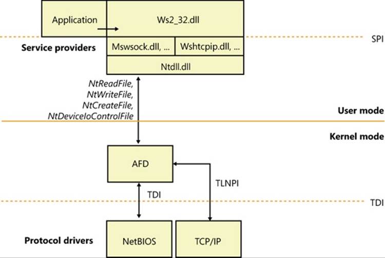
Figure 7-4. Winsock implementation
Winsock Kernel
To enable kernel-mode drivers and modules to have access to networking API interfaces similar to those available to user-mode applications, Windows implements a socket-based networking programming interface called Winsock Kernel (WSK). WSK replaces the legacy TDI API interface present on older versions of Windows but maintains the TDI API interface for transport providers. Compared to TDI, WSK provides better performance, better security, better scalability, and a much easier programming paradigm, because it relies less on internal kernel behavior and more on socket-based semantics. Additionally, WSK was written to take full advantage of the latest technologies in the Windows TCP/IP stack, which TDI was not originally anticipated to support. As shown in Figure 7-5, WSK makes use of the Network Module Registrar (NMR) component of Windows (part of %SystemRoot%\System32\drivers\NetIO.sys) to attach and detach from transport protocols, and it can be used, just like Winsock, to support many types of network clients—for example, the Http.sys driver for the HTTP Server API (mentioned later in the chapter) is a WSK client. Using NMR with WSK is rather complicated, so registration-support APIs are provided to register with WSK (WskRegister, WskDeregister, WskCaptureProviderNPI, and WskReleaseProviderNPI).
NOTE
The Raw transport protocol is not really a protocol and does not perform any encapsulation of the user data. This allows the client to directly control the contents of the frames transmitted and received by the network interface.
WSK enhances security by restricting address sharing—which allows multiple sockets to use the same transport (TCP/IP) address—through the use of nondefault sharing and security descriptors on addresses. WSK uses the security descriptor specified by the first socket for an address, and it checks the owning process and thread for each subsequent attempt to use that address.
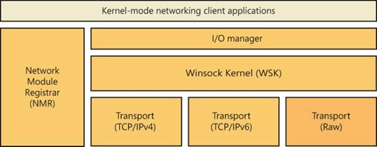
Figure 7-5. WSK overview
WSK Implementation
WSK’s implementation is shown in Figure 7-6. At its core is the WSK subsystem itself, which uses the Next Generation TCP/IP Stack (%SystemRoot%\System32\Drivers\Tcpip.sys) and the NetIO support library (%SystemRoot%\System32\Drivers\NetIO.sys) but is actually implemented in AFD. The subsystem is responsible for the provider side of the WSK API. The subsystem interfaces with the TCP/IP transport protocols (shown at the bottom of Figure 7-5). Attached to the WSK subsystem are WSK clients, which are kernel-mode drivers that implement the client-side WSK API in order to perform network operations. The WSK subsystem calls WSK clients to notify them of asynchronous events.
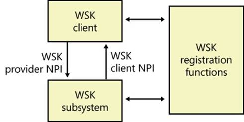
Figure 7-6. WSK implementation
WSK clients are bound to the WSK subsystem through the NMR or through the WSK’s registration functions, which allow WSK clients to dynamically detect when the WSK subsystem becomes available and then load their own dispatch table to describe the provider and client-side implementations of the WSK API. These implementations provide the standard WSK socket-based functions, such as WskSocket, WskAccept, WskBind, WskConnect, WskReceive, and WskSend, which have similar semantics (but not necessarily similar parameters) as their user-mode Winsock counterparts. However, unlike user-mode Winsock, the WSK subsystem defines four kinds of socket categories, which identify which functions and events are available:
§ Basic sockets, which are used only to get and set information on the transport. They cannot be used to send or receive data or be bound to an address.
§ Listening sockets, which are used for sockets that accept only incoming connections.
§ Datagram sockets, which are used solely for sending and receiving datagrams.
§ Connection-oriented sockets, which support all the functionality required to send and receive network traffic over an established connection.
Apart from the socket functions described, WSK also provides events through which clients are notified of network status. Unlike the model for socket functions, in which a client controls the connection, events allow the subsystem to control the connection and merely notify the client. These include the WskAcceptEvent, WskInspectEvent, WskAbortEvent, WskReceiveFromEvent, WskReceiveEvent, WskDisconnectEvent, and WskSendBacklogEvent routines.
Finally, like user-mode Winsock, WSK can be extended through extension interfaces that clients can associate with sockets. These extensions can enhance the default functionality provided by the WSK subsystem.
Remote Procedure Call
Remote procedure call (RPC) is a network programming standard originally developed in the early 1980s. The Open Software Foundation (now The Open Group) made RPC part of the distributed computing environment (DCE) distributed computing standard. Although there is a second RPC standard, SunRPC, the Microsoft RPC implementation is compatible with the OSF/DCE standard. RPC builds on other networking APIs, such as named pipes or Winsock, to provide an alternate programming model that in some respects hides the details of networking programming from an application developer. Fundamentally, RPC provides a mechanism for creating programs that are distributed across a network, with portions of the application running transparently on one or more systems.
RPC Operation
An RPC facility is one that allows a programmer to create an application consisting of any number of procedures, some that execute locally and others that execute on remote computers via a network. It provides a procedural view of networked operations rather than a transport-centered view, thus simplifying the development of distributed applications.
Networking software is traditionally structured around an I/O model of processing. In Windows, for example, a network operation is initiated when an application issues an I/O request. The operating system processes the request accordingly by forwarding it to a redirector, which acts as a remote file system by making the client interaction with the remote file system invisible to the client. The redirector passes the operation to the remote file system, and after the remote system fulfills the request and returns the results, the local network card interrupts. The kernel handles the interrupt, and the original I/O operation completes, returning results to the caller.
RPC takes a different approach altogether. RPC applications are like other structured applications, with a main program that calls procedures or procedure libraries to perform specific tasks. The difference between RPC applications and regular applications is that some of the procedure libraries in an RPC application are stored and execute on remote computers, as shown in Figure 7-7, whereas others execute locally.
To the RPC application, all the procedures appear to execute locally. In other words, instead of making a programmer actively write code to transmit computational or I/O-related requests across a network, handle network protocols, deal with network errors, wait for results, and so forth, RPC software handles these tasks automatically. And the Windows RPC facility can operate over any available transport protocols loaded into the system.
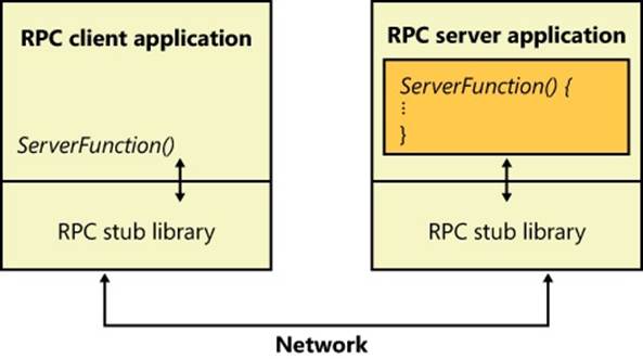
Figure 7-7. RPC operation
To write an RPC application, the programmer decides which procedures will execute locally and which will execute remotely. For example, suppose an ordinary workstation has a network connection to a supercomputer (a very fast machine usually designed for high-speed vector operations). If the programmer were writing an application that manipulated large matrices, it would make sense from a performance perspective to offload the mathematical calculations to the supercomputer by writing the program as an RPC application.
RPC applications work like this: As an application runs, it calls local procedures as well as procedures that aren’t present on the local machine. To handle the latter case, the application is linked to a local library or DLL that contains stub procedures, one for each remote procedure. For simple applications, the stub procedures are statically linked with the application, but for bigger components the stubs are included in separate DLLs. In DCOM, covered later in the chapter, the latter method is typically used. The stub procedures have the same name and use the same interface as the remote procedures, but instead of performing the required operations, the stub takes the parameters passed to it and marshals them for transmission across the network. Marshaling parameters means ordering and packaging them in a particular way to suit a network link, such as resolving references and picking up a copy of any data structures that a pointer refers to.
The stub then calls RPC run-time procedures that locate the computer where the remote procedure resides, determines which network transport mechanisms that computer uses, and sends the request to it using local transport software. When the remote server receives the RPC request, it unmarshals the parameters (the reverse of marshaling), reconstructs the original procedure call, and calls the procedure with the parameters passed from the calling system. When the server finishes, it performs the reverse sequence to return results to the caller.
In addition to the synchronous function-call-based interface described here, Windows RPC also supports asynchronous RPC. Asynchronous RPC lets an RPC application execute a function but not wait until the function completes to continue processing. Instead, the application can execute other code and later, when a response has arrived from the server, the RPC runtime notifies the client that the operation has completed. The RPC runtime uses the notification mechanism requested by the client. If the client uses an event synchronization object for notification, it waits for the signaling of the event object by calling either WaitForSingleObject or WaitForMultipleObjects. If the client provides an asynchronous procedure call (APC), the runtime queues the execution of the APC to the thread that executed the RPC function. (The APC will not be delivered until the requesting thread enters an alertable wait state. See Chapter 3, for more information on APCs.) If the client program uses an I/O completion port as its notification mechanism, it must call GetQueuedCompletionStatus to learn of the function’s completion. Alternatively, a client can poll for completion by calling RpcAsyncGetCallStatus.
In addition to the RPC runtime, Microsoft’s RPC facility includes a compiler, called the Microsoft Interface Definition Language (MIDL) compiler. The MIDL compiler simplifies the creation of an RPC application by generating the necessary stub routines. The programmer writes a series of ordinary function prototypes (assuming a C or C++ application) that describe the remote routines and then places the routines in a file. The programmer then adds some additional information to these prototypes, such as a network-unique identifier for the package of routines and a version number, plus attributes that specify whether the parameters are input, output, or both. The embellished prototypes form the developer’s Interface Definition Language (IDL) file.
Once the IDL file is created, the programmer compiles it with the MIDL compiler, which produces client-side and server-side stub routines (mentioned previously), as well as header files to be included in the application. When the client-side application is linked to the stub routines file, all remote procedure references are resolved. The remote procedures are then installed, using a similar process, on the server machine. A programmer who wants to call an existing RPC application need only write the client side of the software and link the application to the local RPC run-time facility.
The RPC runtime uses a generic RPC transport provider interface to talk to a transport protocol. The provider interface acts as a thin layer between the RPC facility and the transport, mapping RPC operations onto the functions provided by the transport. The Windows RPC facility implements transport provider DLLs for named pipes, HTTP, TCP/IP, and UDP. In a similar fashion, the RPC facility is designed to work with different network security facilities.
Most of the Windows networking services are RPC applications, which means that both local applications and applications on remote computers might call them. Thus, a remote client computer might call the server service to list shares, open files, write to print queues, or activate users on your server, all subject to security constraints, of course. The majority of client-management APIs are implemented using RPC.
Server name publishing, which is the ability of a server to register its name in a location accessible for client lookup, is in RPC and is integrated with Active Directory. If Active Directory isn’t installed, the RPC name locator services fall back on NetBIOS broadcast. This behavior allows RPC to function on stand-alone servers and workstations.
RPC Security
Windows RPC includes integration with security support providers (SSPs) so that RPC clients and servers can use authenticated or encrypted communications. When an RPC server wants secure communication, it tells the RPC runtime what authentication service to add to the list of available authentication services. When a client wants to use secure communication, it binds to the server. At that time, it must tell the RPC runtime the authentication service and authentication level it wants. Various authentication levels exist to ensure that only authorized clients connect to a server, verify that each message a server receives originates at an authorized client, check the integrity of RPC messages to detect manipulation, and even encrypt RPC message data. Obviously, higher authentication levels require more processing. The client can also optionally specify the server principal name. A principal is an entity that the RPC security system recognizes. The server must register its SSP-specific principal name with an SSP.
An SSP handles the details of performing network communication authentication and encryption, not only for RPC but also for Winsock. Windows includes a number of built-in SSPs, including a Kerberos SSP to implement Kerberos version 5 authentication (including AES support) and Secure Channel (SChannel), which implements Secure Sockets Layer (SSL) and the Transport Layer Security (TLS) protocols. SChannel also supports TLS and SSL extensions, which allow you to use the AES cipher as well as elliptic curve cryptographic (ECC) ciphers on top of the protocols. Also, because it supports an open cryptographic interface (OCI) and crypto-agile capabilities, SChannel allows an administrator to replace or add to the existing cryptographic algorithms. In the absence of a specified SSP, RPC software uses the built-in security of the underlying transport. Some transports, such as named pipes or local RPC, have built-in security. Others, like TCP, do not, and in this case RPC makes unsecure calls in the absence of a specified SSP.
NOTE
The use of unencrypted RPC might pose serious security issues for your organization.
Another feature of RPC security is the ability of a server to impersonate the security identity of a client with the RpcImpersonateClient function. After a server has finished performing impersonated operations on behalf of a client, it returns to its own security identity by callingRpcRevertToSelf or RpcRevertToSelfEx. (See Chapter 6 for more information on impersonation.)
RPC Implementation
RPC implementation is depicted in Figure 7-8, which shows that an RPC-based application links with the RPC run-time DLL (%SystemRoot%\System32\Rpcrt4.dll). The RPC run-time DLL provides marshaling and unmarshaling functions for use by an application’s RPC function stubs as well as functions for sending and receiving marshaled data. The RPC run-time DLL includes support routines to handle RPC over a network as well as a form of RPC called local RPC. Local RPC can be used for communication between two processes located on the same system, and the RPC run-time DLL uses the advanced local procedure call (ALPC) facilities in kernel mode as the local networking API. (See Chapter 3 for more information on ALPCs.) When RPC is based on nonlocal communication mechanisms, the RPC run-time DLL uses the Winsock or named pipe APIs.
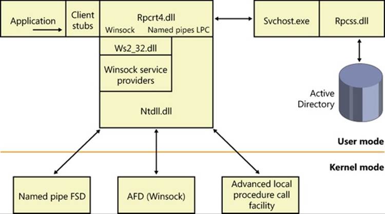
Figure 7-8. RPC implementation
The RPC subsystem (RPCSS—%SystemRoot%\System32\Rpcss.dll) is implemented as a Windows service. RPCSS is itself an RPC application that communicates with instances of itself on other systems to perform name lookup, registration, and dynamic endpoint mapping. (For clarity, Figure 7-8 doesn’t show RPCSS linked with the RPC run-time DLL.)
Windows also includes support for RPC in kernel mode through the kernel-mode RPC driver (%SystemRoot%\System32\Drivers\Msrpc.sys). Kernel-mode RPC is for internal use by the system and is implemented on top of ALPC. Winlogon includes an RPC server with a documented set of interfaces that user-mode RPC clients might call, while Win32k.sys includes an RPC client that communicates with Winlogon for internal notifications, such as the secure attention sequence (SAS). (See Chapter 6 for more information.) The TCP/IP stack in Windows (as well as the WFP) also uses kernel-mode RPC to communicate with the Network Storage Interface (NSI) service, which handles network configuration information.
Web Access APIs
To ease the development of Internet applications, Windows provides both client and server Internet APIs. By using the APIs, applications can provide HTTP services and use FTP and HTTP services without knowledge of the intricacies of the corresponding protocols. The client APIs include Windows Internet, also known as WinInet, which enables applications to interact with the FTP and HTTP protocols, and WinHTTP, which enables applications to interact with the HTTP protocol and is more suitable than WinInet in certain situations (Windows services and middle-tier applications). HTTP Server is a server-side API that enables the development of web server applications.
WinInet
WinInet supports the HTTP, FTP, and Gopher protocols. The APIs break down into sub-API sets specific to each protocol. Using the FTP-related APIs—such as InternetConnect to connect to an HTTP server, followed by HttpOpenRequest to open an HTTP request handle,HttpSendRequestEx to send a request to the sever and receive a response, InternetWriteFile to send a file, and InternetReadFileEx to receive a file—an application developer avoids the details of establishing a connection and formatting TCP/IP messages to the various protocols. The HTTP-related APIs also provide cookie persistence, client-side file caching, and automatic credential dialog handling. WinInet is used by core Windows components such as Windows Explorer and Internet Explorer.
NOTE
WinINet does not support server implementations or use by services. For these types of usage, use WinHTTP instead.
WinHTTP provides an abstraction of the HTTP v1.1 protocol for HTTP client applications similar to what the WinInet HTTP-related APIs provide. However, whereas the WinInet HTTP API is intended for user-interactive, client-side applications, the WinHTTP API is designed for server applications that communicate with HTTP servers. Server applications are often implemented as Windows services that do not provide a user interface and so do not desire the dialog boxes that WinInet APIs display. In addition, the WinHTTP APIs are more scalable (such as supporting uploads of greater than 4 GB) and offer security functionality, such as thread impersonation, that is not available from the WinInet APIs.
HTTP
Using the HTTP Server API implemented by Windows, server applications can register to receive HTTP requests for particular URLs, receive HTTP requests, and send HTTP responses. The HTTP Server API includes SSL support so that applications can exchange data over secure HTTP connections. The API includes server-side caching capabilities, synchronous and asynchronous I/O models, and both IPv4 and IPv6 addressing. The HTTP server APIs are used by IIS and other Windows services that rely on HTTP as a transport.
The HTTP Server API, which applications access through %SystemRoot%\System32\Httpapi.dll, relies on the kernel-mode %SystemRoot%\System32\Drivers\Http.sys driver. Http.sys starts on demand the first time any application on the system calls HttpInitialize. Applications then call HttpCreateServerSession to initialize a server session for the HTTP Server API. Next they use HttpCreateRequestQueue to create a private request queue and HttpCreateUrlGroup to create a URL group, specifying the URLs that they want to handle requests for withHttpAddUrlToUrlGroup. Using the request queues and their registered URLs (which they associate by using HttpSetUrlGroupProperty), Http.sys allows more than one application to service HTTP requests on a given port (port 80 for example), with each servicing HTTP requests to different parts of the URL namespace, as shown in Figure 7-9.
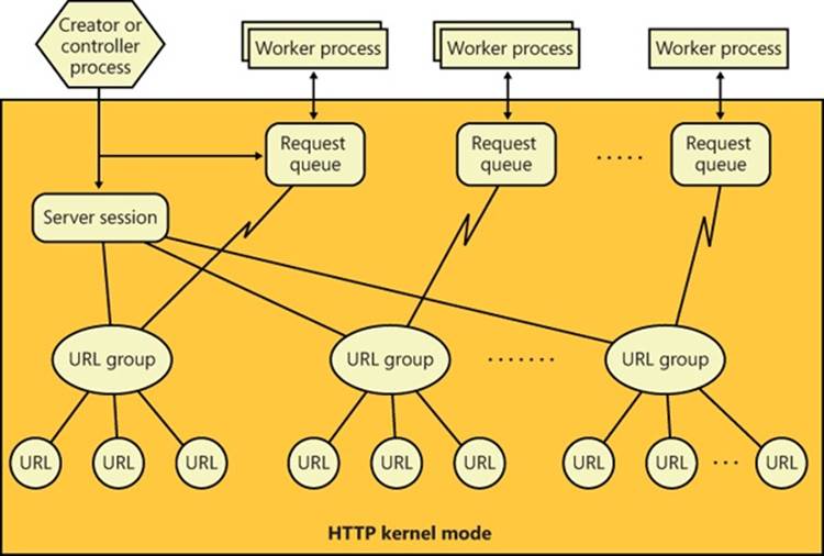
Figure 7-9. HTTP request queues and URL groups
HttpReceiveHttpRequest receives incoming requests directed at registered URLs, and HttpSendHttpResponse sends HTTP responses. Both functions offer asynchronous operation so that an application can use GetOverlappedResult or I/O completion ports to determine when an operation is completed.
Applications can use Http.sys to cache data in nonpaged physical memory by calling HttpAddFragmentToCache and associating a fragment name (specified as a URL prefix) with the cached data. Http.sys invokes the memory manager function MmAllocatePagesForMdlEx to allocate unmapped physical pages. (For large requests, Http.sys also attempts to use large pages to optimize access to the buffered data.) When Http.sys requires a virtual address mapping for the physical memory described by an entry in the cache—for instance, when it copies data to the cache or sends data from the cache—it uses MmMapLockedPagesSpecifyCache and then MmUnmapLockedPages after it completes its access. Http.sys maintains cached data until an application invalidates it or an optional application-specified timeout associated with the data expires. Http.sys also trims cached data in a worker thread that wakes up when the low-memory notification event is signaled. (See Chapter 10, “Memory Management,” in Part 2 for information on the low-memory notification event.) When an application specifies one or more fragment names in a call to HttpSendHttpResponse, Http.sys passes a pointer to the cached data in physical memory to the TCP/IP driver and avoids a copy operation. Http.sys also contains code for performing server-side authentication, including full SSL support, which removes the need to call back to the user-mode API to perform encryption and decryption of traffic.
Finally, the HTTP Server API contains many configuration options that clients can use to set functionality, such as authentication policies, bandwidth throttling, logging, connection limits, server state, response caching, and SSL certificate binding.
Named Pipes and Mailslots
Named pipes and mailslots are programming APIs for interprocess communication. Named pipes provide for reliable bidirectional communications, whereas mailslots provide unreliable, unidirectional data transmission. An advantage of mailslots is that they support broadcast capability. In Windows, both APIs make use of standard Windows security authentication and authorization mechanisms, which allow a server to control precisely which clients can connect to it.
The names that servers assign to named pipes and clients conform to the Windows Universal Naming Convention (UNC), which is a protocol-independent way to identify resources on a Windows network. The implementation of UNC names is described later in the chapter.
Named-Pipe Operation
Named-pipe communication consists of a named-pipe server and a named-pipe client. A named-pipe server is an application that creates a named pipe to which clients can connect. A named pipe’s name has the format \\Server\Pipe\PipeName. The Server component of the name specifies the computer on which the named-pipe server is executing. (A named-pipe server can’t create a named pipe on a remote system.) The name can be a DNS name (for example, mspress.microsoft.com), a NetBIOS name (mspress), or an IP address (131.107.0.1). The Pipecomponent of the name must be the string “Pipe”, and PipeName is the unique name assigned to a named pipe. The unique portion of the named pipe’s name can include subdirectories; an example of a named-pipe name with a subdirectory is \\MyComputer\Pipe\MyServerApp\ConnectionPipe.
A named-pipe server uses the CreateNamedPipe Windows function to create a named pipe. One of the function’s input parameters is a pointer to the named-pipe name, in the form \\.\Pipe\PipeName. The “\\.\” is a Windows-defined alias for “this system,” because a pipe must be created on the local system (although it can be accessed from a remote system). Other parameters the function accepts include an optional security descriptor that protects access to the named pipe, a flag that specifies whether the pipe should be bidirectional or unidirectional, a value indicating the maximum number of simultaneous connections the pipe supports, and a flag specifying whether the pipe should operate in byte mode or message mode.
Most networking APIs operate only in byte mode, which means that a message sent with one send function might require the receiver to perform multiple receive operations, building up the complete message from fragments. A named pipe operating in message mode simplifies the implementation of a receiver because there is a one-to-one correspondence between send and receive requests. A receiver therefore obtains an entire message each time it completes a receive operation and doesn’t have to concern itself with keeping track of message fragments.
The first call to CreateNamedPipe for a particular name creates the first instance of that name and establishes the behavior of all named-pipe instances having that name. A server creates additional instances, up to the maximum specified in the first call, with additional calls toCreateNamedPipe. After creating at least one named-pipe instance, a server executes the ConnectNamedPipe Windows function, which enables the named pipe the server created to establish connections with clients. ConnectNamedPipe can be executed synchronously or asynchronously, and it doesn’t complete until a client establishes a connection with the instance (or an error occurs).
A named-pipe client uses the Windows CreateFile or CallNamedPipe function, specifying the name of the pipe a server has created, to connect to a server. If the server has performed a ConnectNamedPipe call, the client’s security profile and the access it requests to the pipe (read, write) are validated against the named pipe’s security descriptor. (See Chapter 6 for more information on the security-check algorithms Windows uses.) If the client is granted access to a named pipe, it receives a handle representing the client side of a named-pipe connection and the server’s call to ConnectNamedPipe completes.
After a named-pipe connection is established, the client and server can use the ReadFile and WriteFile Windows functions to read from and write to the pipe. Named pipes support both synchronous and asynchronous operations for message transmittal, depending upon how the handle to the pipe was opened. Figure 7-10 shows a server and client communicating through a named-pipe instance.
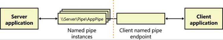
Figure 7-10. Named-pipe communications
Another characteristic of the named-pipe networking API is that it allows a server to impersonate a client by using the ImpersonateNamedPipeClient function. See the Impersonation section in Chapter 6 for a discussion of how impersonation is used in client/server applications. A second advanced area of functionality of the named-pipe API is that it allows for atomic send and receive operations through the TransactNamedPipe API, which behaves according to a simple transactional model in which a message is both sent and received in the same operation. In other words, it combines a write operation and a read operation into a single operation by not completing a write request until it has been read by the recipient.
Mailslot Operation
Mailslots provide an unreliable, unidirectional, multicast network transport. Multicast is a term used to describe a sender sending a message on the network to one or more specific listeners, which is different from a broadcast, which all systems would receive. One example of an application that can use this type of communication is a time-synchronization service, which might send a source time across the domain every few seconds. Such a message would be received by all applications listening on the particular mailslot. Receiving the source-time message isn’t crucial for every computer on the network (because time updates are sent relatively frequently); therefore, a source-time message is a good example for the use of mailslots, because the loss of a message will not cause any harm.
Like named pipes, mailslots are integrated with the Windows API. A mailslot server creates a mailslot by using the CreateMailslot function. CreateMailslot accepts a UNC name of the form “\\.\Mailslot\MailslotName” as an input parameter. Again like named pipes, a mailslot server can create mailslots only on the machine it’s executing on, and the name it assigns to a mailslot can include subdirectories. CreateMailslot also takes a security descriptor that controls client access to the mailslot. The handles returned by CreateMailslot are overlapped, which means that operations performed on the handles, such as sending and receiving messages, are asynchronous.
Because mailslots are unidirectional and unreliable, CreateMailslot doesn’t take many of the parameters that CreateNamedPipe does. After it creates a mailslot, a server simply listens for incoming client messages by executing the ReadFile function on the handle representing the mailslot.
Mailslot clients use a naming format similar to that used by named-pipe clients but with variations that make it possible to send messages to all the mailslots of a given name within the client’s domain or a specified domain. To send a message to a particular instance of a mailslot, the client calls CreateFile, specifying the computer-specific name. An example of such a name is “\\Server\Mailslot\MailslotName”. (The client can specify “\\.\” to represent the local computer.) If the client wants to obtain a handle representing all the mailslots of a given name on the domain it’s a member of, it specifies the name in the format “\\*\Mailslot\MailslotName”, and if the client wants to broadcast to all the mailslots of a given name within a different domain, the format it uses is “\\DomainName\Mailslot\MailslotName”.
After obtaining a handle representing the client side of a mailslot, the client sends messages by calling WriteFile. Because of the way mailslots are implemented, only messages smaller than 424 bytescan be sent. If a message is larger than 424 bytes, the mailslot implementation uses a reliable communications mechanism that requires a one-to-one client/server connection, which precludes multicast capability. This limitation makes mailslots generally unsuitable for messages larger than 424 bytes. Figure 7-11 shows an example of a client broadcasting to multiple mailslot servers within a domain.
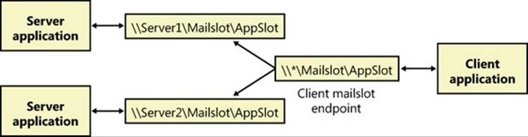
Figure 7-11. Mailslot broadcast
Named Pipe and Mailslot Implementation
As evidence of their tight integration with Windows, named-pipe and mailslot functions are all implemented in the Kernel32.dll Windows client-side DLL. ReadFile and WriteFile, which are the functions applications use to send and receive messages using named pipes or mailslots, are the primary Windows I/O routines. The CreateFile function, which a client uses to open either a named pipe or a mailslot, is also a standard Windows I/O routine. However, the names specified by named-pipe and mailslot applications specify file-system namespaces managed by the named-pipe file-system driver (%SystemRoot%\System32\Drivers\Npfs.sys) and the mailslot file-system driver (%SystemRoot%\System32\Drivers\Msfs.sys), as shown in Figure 7-12.
The name- pipe file-system driver creates a device object named \Device\NamedPipe and a symbolic link to that object named \Global??\Pipe. The mailslot file-system driver creates a device object named \Device\Mailslot and a symbolic link named “\Global??\Mailslot”, which points to that device object. (See Chapter 3 for an explanation of the \Global?? object manager directory.) Names passed to CreateFile of the form “\\.\Pipe\...” and “\\.\Mailslot\...” have their prefix of “\\.\” translated to “\Global??\” so that the names resolve through a symbolic link to a device object. The special functions CreateNamedPipe and CreateMailslot use the corresponding native functions NtCreateNamedPipeFile and NtCreateMailslotFile, which ultimately call IoCreateFile.
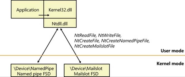
Figure 7-12. Named-pipe and mailslot implementation
Later in the chapter, we’ll discuss how the redirector file system driver is involved when a name that specifies a remote named pipe or mailslot resolves to a remote system. However, when a named pipe or mailslot is created by a server or opened by a client, the appropriate file-system driver (FSD) on the machine where the named pipe or mailslot is located is eventually invoked. The reason that named pipes and mailslots are implemented as FSDs is that they can take advantage of the existing infrastructure in the object manager, the I/O manager, the redirector (covered later in this chapter), and the Server Message Block (SMB) protocol. (For more information about SMB, see Chapter 12, “File Systems,” in Part 2.) This integration results in several benefits:
§ The FSDs use kernel-mode security functions to implement standard Windows security for named pipes and mailslots.
§ Applications can use CreateFile to open a named pipe or mailslot because FSDs integrate with the object manager namespace.
§ Applications can use Windows functions such as ReadFile and WriteFile to interact with named pipes and mailslots.
§ The FSDs rely on the object manager to track handle and reference counts for file objects representing named pipes and mailslots.
§ The FSDs can implement their own named pipe and mailslot namespaces, complete with subdirectories.
EXPERIMENT: LISTING THE NAMED-PIPE NAMESPACE AND WATCHING NAMED-PIPE ACTIVITY
It’s not possible to use the Windows API to open the root of the named-pipe FSD and perform a directory listing, but you can do this by using native API services. The PipeList tool from Sysinternals shows you the names of the named pipes defined on a computer as well as the number of instances that have been created for a name and the maximum number of instances as defined by a server’s call to CreateNamedPipe. Here’s an example of PipeList output:
C:\>pipelist
PipeList v1.01
by Mark Russinovich
http://www.sysinternals.com
Pipe Name Instances Max Instances
--------- --------- -------------
InitShutdown 3 -1
lsass 6 -1
protected_storage 3 -1
ntsvcs 3 -1
scerpc 3 -1
net\NtControlPipe1 1 1
plugplay 3 -1
net\NtControlPipe2 1 1
Winsock2\CatalogChangeListener-394-0 1 1
epmapper 3 -1
Winsock2\CatalogChangeListener-25c-0 1 1
LSM_API_service 3 -1
net\NtControlPipe3 1 1
eventlog 3 -1
net\NtControlPipe4 1 1
Winsock2\CatalogChangeListener-3f8-0 1 1
net\NtControlPipe5 1 1
net\NtControlPipe6 1 1
net\NtControlPipe0 1 1
atsvc 3 -1
Winsock2\CatalogChangeListener-438-0 1 1
Winsock2\CatalogChangeListener-2c8-0 1 1
net\NtControlPipe7 1 1
net\NtControlPipe8 1 1
net\NtControlPipe9 1 1
net\NtControlPipe10 1 1
net\NtControlPipe11 1 1
net\NtControlPipe12 1 1
142CDF96-10CC-483c-A516-3E9057526912 1 1
net\NtControlPipe13 1 1
net\NtControlPipe14 1 1
TSVNCache-000000000001b017 20 -1
TSVNCacheCommand-000000000001b017 2 -1
Winsock2\CatalogChangeListener-2b0-0 1 1
Winsock2\CatalogChangeListener-468-0 1 1
TermSrv_API_service 3 -1
Ctx_WinStation_API_service 3 -1
PIPE_EVENTROOT\CIMV2SCM EVENT PROVIDER 2 -1
net\NtControlPipe15 1 1
keysvc 3 -1
It’s clear from this output that several system components use named pipes as their communications mechanism. For example, the InitShutdown pipe is created by WinInit to accept remote shutdown commands, and the Atsvc pipe is created by the Task Scheduler service to enable applications to communicate with it to schedule tasks. You can determine what process has each of these pipes open by using the object search facility in Process Explorer.
NOTE
A Max Instances value of –1 means that there is no upper limit on the number of instances.
NetBIOS
Until the 1990s, the Network Basic Input/Output System (NetBIOS) programming API had been the most widely used network programming API on PCs. NetBIOS allows for both reliable connection-oriented and unreliable connectionless communication. Windows supports NetBIOS for its legacy applications. Microsoft discourages application developers from using NetBIOS because other APIs, such as named pipes and Winsock, are much more flexible and portable. NetBIOS is supported by the TCP/IP protocol on Windows.
NetBIOS Names
NetBIOS relies on a naming convention whereby computers and network services are assigned a 16-byte NetBIOS name. The sixteenth byte of a NetBIOS name is treated as a modifier that can specify a name as unique or as part of a group. Only one instance of a unique NetBIOS name can be assigned to a network, but multiple applications can assign the same group name. A client can send multicast messages by sending them to a group name.
To support interoperability with Windows NT 4 systems as well as Windows 9x/Me, Windows automatically defines a NetBIOS name for a domain that includes up to the first 15 bytes of the left-most Domain Name System (DNS) name that an administrator assigns to the domain. For example, if a domain were named mspress.microsoft.com, the NetBIOS name of the domain would be mspress.
Another concept used by NetBIOS is that of LAN adapter (LANA) numbers. A LANA number is assigned to every NetBIOS-compatible protocol that layers above a network adapter. For example, if a computer has two network adapters and TCP/IP and NWLink can use either adapter, there would be four LANA numbers. LANA numbers are important because a NetBIOS application must explicitly assign its service name to each LANA through which it’s willing to accept client connections. If the application listens for client connections on a particular name, clients can access the name only via protocols on the network adapters for which the name is registered.
NetBIOS Operation
A NetBIOS server application uses the NetBIOS API to enumerate the LANAs present on a system and assign a NetBIOS name representing the application’s service to each LANA. If the server is connection oriented, it performs a NetBIOS listen command to wait for client connection attempts. After a client is connected, the server executes NetBIOS functions to send and receive data. Connectionless communication is similar, but the server simply reads messages without establishing connections.
A connection-oriented client uses NetBIOS functions to establish a connection with a NetBIOS server and then executes further NetBIOS functions to send and receive data. An established NetBIOS connection is also known as a session. If the client wants to send connectionless messages, it simply specifies the NetBIOS name of the server with the send function.
NetBIOS consists of a number of functions, but they all route through the same interface: Netbios. This routing scheme is the result of a legacy left over from the time when NetBIOS was implemented on MS-DOS as an MS-DOS interrupt service. A NetBIOS application would execute an MS-DOS interrupt and pass a data structure to the NetBIOS implementation that specified every aspect of the command being executed. As a result, the Netbios function in Windows takes a single parameter, which is a data structure that contains the parameters specific to the service the application requests.
EXPERIMENT: USING NBTSTAT TO SEE NETBIOS NAMES
You can use the Nbtstat command, which is included with Windows, to list the active sessions on a system, the NetBIOS-to-TCP/IP name mappings cached on a computer, and the NetBIOS names defined on a computer. Here’s an example of the Nbtstat command with the –n option, which lists the NetBIOS names defined on the computer:
C:\Users\Toby>nbtstat -n
Local Area Connection:
Node IpAddress: [192.168.0.193] Scope Id: []
NetBIOS Local Name Table
Name Type Status
---------------------------------------------
WIN-NLRTEOW2ILZ<00> UNIQUE Registered
WORKGROUP <00> GROUP Registered
WIN-NLRTEOW2ILZ<20> UNIQUE Registered
NetBIOS API Implementation
The components that implement the NetBIOS API are shown in Figure 7-13. The Netbios function is exported to applications by %SystemRoot%\System32\Netbios.dll. Netbios.dll opens a handle to the kernel-mode driver named the NetBIOS emulator(%SystemRoot%\System32\Drivers\Netbios.sys) and issues Windows DeviceIoControl file commands on behalf of an application. The NetBIOS emulator translates NetBIOS commands issued by an application into TDI commands that it sends to protocol drivers.
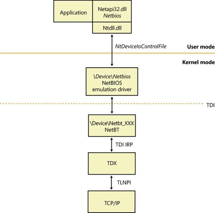
Figure 7-13. NetBIOS API implementation
If an application wants to use NetBIOS over the TCP/IP protocol, the NetBIOS emulator requires the presence of the NetBT driver (%SystemRoot%\System32\Drivers\Netbt.sys). NetBT is known as the NetBIOS over TCP/IP driver and is responsible for supporting NetBIOS semantics that are inherent to the NetBIOS Extended User Interface (NetBEUI) protocol (included in previous versions of Windows) but not the TCP/IP protocol. For example, NetBIOS relies on NetBEUI’s message-mode transmission and NetBIOS name-resolution facilities, so the NetBT driver implements them on top of the TCP/IP protocol.
Other Networking APIs
Windows includes other networking APIs that are used less frequently or are layered on the APIs already described (and outside the scope of this book). Five of these, however—Background Intelligent Transfer Service (BITS), Distributed Component Object Model (DCOM), Message Queuing (MSMQ), Peer-to-Peer Infrastructure (P2P), and Universal Plug and Play (UPnP) with Plug and Play Extensions (PnP-X)—are important enough to the operation of a Windows system and many applications to merit brief descriptions.
Background Intelligent Transfer Service
BITS is a service and an API that provides reliable asynchronous transfer of files between systems, using either the SMB, HTTP, or HTTPS protocol. BITS normally runs in the background, making use of unutilized network bandwidth by monitoring network utilization and throttling itself so that it consumes only resources that would otherwise be unused; however, BITS transfers might also take place in the foreground and compete for resources with other processes running on the system.
BITS keeps track of ongoing, or scheduled, transfers in what are known as transfer jobs (not to be confused with jobs and job objects as described in Chapter 5) for each user. Each job is an entry in a queue and describes the files to transfer, the security context (access tokens) to run under, and the priority of the job. BITS version 4.0 is integrated into BranchCache (described later in this chapter) to further reduce network bandwidth.
BITS is used by many other components in Windows, such as Microsoft Update, Windows Update, Internet Explorer (version 9 and later, for downloading files), Microsoft Outlook (for downloading address books), Microsoft Security Essentials (for downloading daily virus signature updates), and others, making BITS the most widely used network file-transfer system in use today.
BITS provides the following capabilities:
§ Seamless data transfer. Components create BITS transfer jobs that will then run until the files are transferred. When a user logs out, the system restarts, or the system loses network connectivity, BITS pauses the transfer. The transfer resumes from where it left off once the user logs in again or network connectivity is restored. The application that created a transfer job does not need to remain running, but the user must remain logged in, while the transfer is taking place. Transfer jobs created under service accounts (such as Windows Update) are always considered to be logged on, allowing those jobs to run continuously.
§ Multiple transfer types. BITS supports three transfer types: download (server to client), upload (client to server), and upload-reply (client to server, with a notification receipt from the server).
§ Prioritization of transfers. When a transfer job is created, the priority is specified (either Foreground, Background High, Background Normal, or Background Low). All background priority jobs make use only of unutilized network resources, while jobs with foreground priority compete with applications for network resources. If there are multiple jobs, BITS processes them in priority order, using a round-robin scheduling system within a particular priority so that all jobs make progress on their transfers.
§ Secure data transfer. BITS normally runs the transfer job using the security context of the job’s creator, but you can also use the BITS API to specify the credentials to use for impersonating a user. For privacy across the network, you should use the HTTPS protocol.
§ Management. The BITS API consists of methods for creating, starting, stopping, monitoring, enumerating, modifying, or requesting notification of transfer-job status changes. Tools include BITSAdmin (which is deprecated and will be removed in a future version of Windows), and Windows PowerShell cmdlets (the preferred management mechanism).
When downloading files, BITS writes the file to a temporary hidden file in the destination directory. Of course, BITS will impersonate the user to ensure that file-system security and quotas are enforced properly. When the application calls the IBackgroundCopyJob::Complete method (or the Complete-BitsTransfer cmdlet in PowerShell), BITS renames the temporary files to their destination names, and the files are available to the client. If there is already a file in the destination directory with the same name, BITS overwrites the file.
When uploading files, by default, BITS does not allow overwriting an existing file. When the transfer is finished and BITS would overwrite the file, an error is returned to the client. To allow overwrites, set the BITSAllowOverwrites property to True in the Internet Information Services (IIS) metabase using PowerShell or Windows Management Instrumentation (WMI) scripting.
The BITS server is a server-side component that lets you configure an IIS server to allow BITS clients to perform file transfers to IIS virtual directories. Upon completion of a file upload, the BITS server can notify a web application of the new file’s presence (via an HTTP POST message) so the web application can process the uploaded files.
The BITS server extends IIS to support throttled, restartable uploads of files. To make use of the upload feature, you must create an IIS virtual directory on the server where you want the clients to upload their files. BITS adds properties to the IIS metabase for the virtual directory you create and uses these properties to determine how to upload the files.
For security reasons, BITS will not permit uploading files to a virtual directory that has scripting and execute permissions enabled. If you upload a file to a virtual directory that has these permissions enabled, the job will fail. Also, BITS does not require the virtual directory to be write-enabled, so it is recommended that you turn off write access to the virtual directory; however, the user must have write access to the physical directory.
In some cases, the BITS Compact Server might be used instead of IIS. The Compact Server is intended for use by enterprise and small business customers that meet the following conditions:
§ The anticipated usage is a maximum of 25 URL groups, and each URL group supports up to three simultaneous file transfers
§ File transfers occur between systems in the same domain or mutually trusted domains
§ File transfers are not intended for Internet-facing clients
Figure 7-14 demonstrates how to load the BITS module within PowerShell, and some of the BITS PowerShell cmdlets.
Figure 7-15 demonstrates the use of the BITSAdmin tool, which is now deprecated in favor of PowerShell for managing and using BITS.
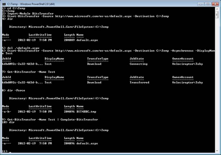
Figure 7-14. Using BITS from PowerShell
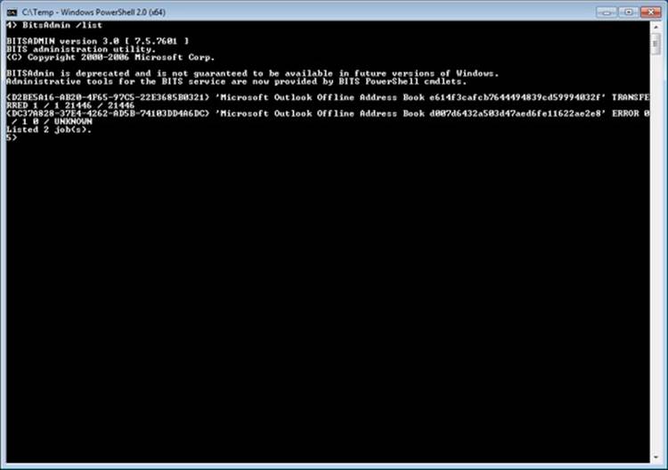
Figure 7-15. BitsAdmin tool
Figure 7-16 shows BITS messages written to the event log.
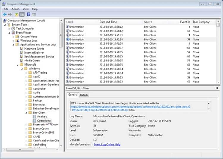
Figure 7-16. BITS messages in the event log
Peer-to-Peer Infrastructure
Peer-to-Peer Infrastructure is a set of APIs that cover different technologies to enhance the Windows networking stack by providing flexible peer-to-peer (P2P) support for applications and services. The P2P infrastructure covers four major technologies, shown in Figure 7-17.
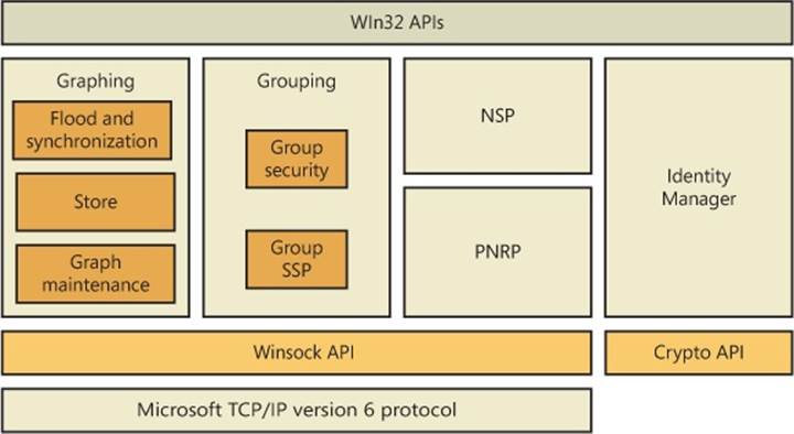
Figure 7-17. Peer-to-peer architecture
Here are the major peer-to-peer components:
§ Peer-to-Peer Graphing. Allows applications to pass data between peers efficiently and reliably by using nodes and events.
§ Peer-to-Peer Namespace Provider. Enables serverless name resolution of peers and their services (described later in the Name Resolution section).
§ Peer-to-Peer Grouping. Combines graphing and namespace technologies to group and isolate services and/or peers into a defined group and uniquely identify it.
§ Peer-to-Peer Identity Manager. Enhances the services offered by the namespace provider to securely create, publish, and identify peer names, as well as to identify group members that are part of the grouping API.
The Peer-to-Peer Infrastructure in Windows is also paired with the Peer-to-Peer Collaboration Interface, which adds support for creating collaborative P2P applications (such as online games and group instant messaging) and supersedes the Real-Time Communications (RTC) architecture in earlier versions of Windows. It also provides presence capabilities through the People Near Me (PNM) architecture.
DCOM
Microsoft’s COM API lets applications consist of different components, each component being a replaceable, self-contained module. A COM object exports an object-oriented interface to methods for manipulating the data within the object. Because COM objects present well-defined interfaces, developers can implement new objects to extend existing interfaces and dynamically update applications with the new support.
DCOM (Distributed Component Object Model) extends COM by letting an application’s components reside on different computers, which means that applications don’t need to be concerned that one COM object might be on the local computer and another might be across the network. DCOM thus provides location transparency, which simplifies developing distributed applications. DCOM isn’t a self-contained API but relies on RPC to carry out its work.
Message Queuing
Message Queuing is a general-purpose platform for developing distributed applications that take advantage of loosely coupled messaging. Message Queuing is therefore an API and a messaging infrastructure. Its flexibility comes from the fact that its queues serve as message repositories in which senders can queue messages for receivers, and receivers can de-queue the messages at their discretion. Senders and receivers do not need to establish connections to use Message Queuing, nor do they need to be executing at the same time, which allows for disconnected asynchronous message exchange.
A notable feature of Message Queuing is that it is integrated with Microsoft Transaction Server (MTS) and SQL Server, so it can participate in Microsoft Distributed Transaction Coordinator (MS DTC) coordinated transactions. Using MS DTC with Message Queuing allows you to develop reliable transaction functionality for three-tier applications.
UPnP with PnP-X
Universal Plug and Play is an architecture for peer-to-peer network connectivity of intelligent appliances, devices, and control points. It is designed to bring easy-to-use, flexible, standards-based connectivity to ad-hoc, managed, or unmanaged networks, whether these networks are in the home, in small businesses, or attached directly to the Internet. Universal Plug and Play is a distributed, open networking architecture that uses existing TCP/IP and Web technologies to enable seamless proximity networking in addition to control and data transfer among networked devices.
Universal Plug and Play supports zero-configuration, invisible networking, and automatic discovery for a range of device categories from a wide range of vendors. This enables a device to dynamically join a network, obtain an IP address, and convey its capabilities upon request. Then other control points can use the Control Point API with UPnP technology to learn about the presence and capabilities of other devices. A device can leave a network smoothly and automatically when it is no longer in use.
Plug and Play Extensions (PnP-X), shown in Figure 7-18, is an additional component of Windows that allows network-attached devices to integrate with the Plug and Play manager in the kernel. With PnP-X, network-connected devices are shown in the Device Manager like locally attached devices and provide the same installation, management, and behavioral experience as a local device. (For example, installation is performed through the standard Add New Hardware Wizard.)
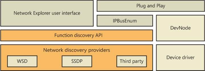
Figure 7-18. PnP-X implementation
PnP-X uses a virtual network bus driver that uses an IP bus enumerator service (%SystemRoot%\System32\Ipbusenum.dll) to discover PnP-X compatible devices, which include UPnP devices (through the Simple Service Discovery Protocol) and the newer Device Profile for Web Services (DPWS) devices (using the WS-Discovery protocol). The IP bus enumerator reports devices it discovers to the Plug and Play manager, which uses user-mode Plug and Play manager services if needed (such as for driver installation). It’s similar to wireless discovery (like Bluetooth) and unlike wired device discovery (like USB), however, PnP-X enumeration and driver installation must be explicitly requested by a user from the Network Explorer.
NOTE
DPWS v1.1 became an OASIS standard in June 2009 and has goals similar to those of UPnP, but it is tightly integrated with web services standards and frameworks and allows greater extensibility than UPnP.
Multiple Redirector Support
Applications access file-system resources on remote systems (often called file shares) using UNC paths—for example, \\servername\sharename\file. Resources can be accessed directly using the UNC name if it is already known and the logged-on user’s credentials are sufficient. Optionally, the Windows Networking (WNet) API can be used to enumerate computers and resources that those computers export for sharing, map drive letters to UNC paths, and explicitly specify credentials. To access SMB servers from a client, Microsoft supplies an SMB client, which has a kernel-mode component called the mini-redirector and a user-mode component called the Workstation service. (SMB is described in Chapter 12 in Part 2.) Microsoft also makes available redirectors that can access WebDAV resources, NFS v2/v3 resources (Windows Professional and Enterprise editions only), and Terminal Services–shared drives. Third parties can add their own redirectors to Windows. In this section, we’ll examine the software that decides which redirector to invoke for file access using UNC paths. Here are the responsible components:
§ Multiple Provider Router (MPR) is a DLL (%SystemRoot%\System32\Mpr.dll) that determines which network to access when an application uses the Windows WNet API for browsing remote file resources.
§ Multiple UNC Provider (MUP) is a driver (%SystemRoot%\System32\Drivers\Mup.sys) that determines which network to access when an application uses the Windows I/O APIs to open remote files through UNC paths or drive letters mapped to UNC paths.
Multiple Provider Router
The Windows WNet functions allow applications (including the Network and Sharing Center) to connect to network resources, such as file servers and printers, and to browse the different share points. Because the WNet API can be called to work across different networks using different transport protocols, software must be present to send the request to the correct network and to understand the results that the remote server returns. Figure 7-19 shows the redirector software responsible for these tasks.
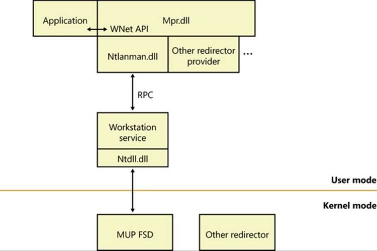
Figure 7-19. MPR components
A provider is software that establishes Windows as a client of a remote network server. Some of the operations a WNet provider performs include making and breaking network connections, as well as supporting network printing. The built-in SMB WNet provider includes a DLL, the Workstation service, and the redirector. Other network vendors need to supply only a DLL and a redirector.
When an application calls a WNet routine, the call passes directly to the MPR DLL. MPR takes the call and determines which network provider recognizes the resource being accessed. Each provider DLL beneath MPR supplies a set of standard functions collectively called thenetwork provider interface. This interface allows MPR to determine which network the application is trying to access and to direct the request to the appropriate WNet provider software. The SMB Workstation service’s provider is %SystemRoot%\System32\Ntlanman.dll, as specified by the ProviderPath value under the HKLM\SYSTEM\CurrentControlSet\Services\LanmanWorkstation\NetworkProvider registry key.
When called by the WNetAddConnection2 or WNetAddConnection3 API function to connect to a remote network resource, MPR checks the HKLM\SYSTEM\CurrentControlSet\Control\NetworkProvider\HwOrder\ProviderOrder registry value to determine which network providers are loaded. It polls them one at a time, in the order in which they’re listed in the registry, until a provider recognizes the resource or until all available providers have been polled. You can change the ProviderOrder by using the Advanced Settings dialog box shown in Figure 7-20. You can access the dialog box by opening the Start menu, typing view network connections in the search box, and pressing Enter. This brings up the Network Connections dialog box. Press the Alt key on the keyboard, which will display the menus in the dialog box. Click on the Advanced drop-down menu, and choose Advanced Settings, and then click on the Provider Order tab.
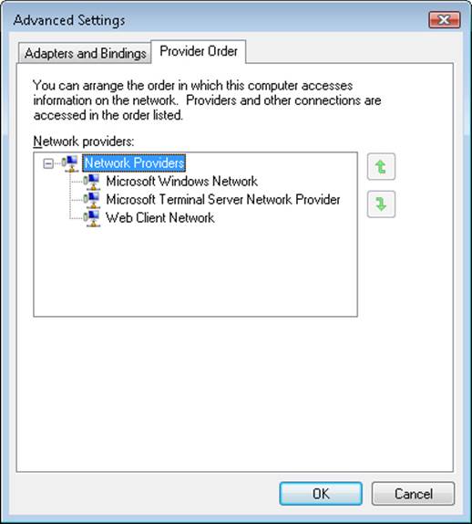
Figure 7-20. The provider order editor
The WNetAddConnection function can also assign a drive letter or device name to a remote resource. When called to do so, WNetAddConnection routes the call to the appropriate network provider. The provider, in turn, creates a symbolic-link object in the object manager’s namespace that maps the drive letter being defined to the redirector (that is, the remote FSD) for that network.
Figure 7-21 shows the Session 0 DosDevices directory corresponding to the LUID of the user who performed the drive-letter mapping, which is where connections to remote file shares are stored. The symbolic link created by network providers relies on MUP to serve as the connection between a network path and the corresponding redirector. The figure shows that MUP creates a device object named \Device\LanmanRedirector, which is itself a symbolic link to \Device\MUP (which is not shown in the figure because the symbolic link is in the \Device directory), with additional text included in the symbolic link’s value indicating to the MUP redirector which mini-redirector the drive letter corresponds to. The “\Global??” directory shows you the drive letters available to the system session—others will be mapped in the session-specific DosDevices directory.
Then, when the WNet or other API calls the object manager to open a resource on a different network, the object manager uses the device object as a jumping-off point into the remote file system. It calls an I/O manager parse method associated with the device object to locate the redirector FSD that can handle the request. (See Chapter 12 in Part 2 for more information on file system drivers.)
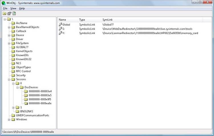
Figure 7-21. Resolving a network resource name
Multiple UNC Provider
The Multiple UNC Provider (MUP, %SystemRoot%\System32\Drivers\mup.sys) is a file-system driver that exposes remote file systems to Windows. It is a single point where file system filter drivers can be layered to filter any and all I/O requests made to remote file systems. (Prior to Windows Vista, there were many inconsistencies and difficulties regarding filtering remote file systems.) MUP receives I/O requests for access to remote file systems (via UNC paths or drive letters mapped to them) and determines which redirector will handle the request. The termredirector is used because it redirects an I/O request to a remote system. Before, and optionally after, calling the redirector, MUP will call any registered surrogate providers that might provide file caching and path rewriting.
MUP implements what is known as a prefix cache, which is a list of which remote file system paths (\\<server name>[\<share name>]) that are handled by each redirector. It is possible that multiple redirectors could handle a particular prefix, so there is a list in the registry (HKLM\System\CurrentControlSet\Control\NetworkProvider\Order\ProviderOrder) containing a comma-separated list of the priority order in which MUP forwards requests to the redirectors. This list is also used to load the providers. Under ProviderOrder, there are two subkeys (HwOrder and Order) containing identical information in a value named ProviderOrder. A typical value is the following:
ProviderOrder REG_SZ RDPNP,LanmanWorkstation,webClient
Each entry specifies the name of a service in HKLM\System\CurrentControlSet\Services, where another subkey named NetworkProvider is found. For example, in the key HKLM\System\CurrentControlSet\Services\RDPNP\NetworkProvider are the following values:
DeviceName REG_SZ \Device\RdpDr
DisplayName REG_EXPAND_SZ @%systemroot%\system32\drprov.dll,-100
Name REG_SZ Microsoft Terminal Services
ProviderPath REG_EXPAND_SZ %SystemRoot%\System32\drprov.dll
The DeviceName value is the name assigned to the kernel-mode redirector’s device object. DisplayName is the formal name of the provider. (This can be either a string or the location of a string in the resource section of a DLL, as seen here.) Name is the name that will be displayed bynet use to identify which redirector owns a particular drive. ProviderPath specifies the path where the provider DLL is located.
NOTE
Not all redirectors are, or have to be, listed in provider order. (Typically, you will see only RDPNP, LanmanWorkstation, webclient listed.) The priority of the redirectors not listed in the registry follows those that are listed in decreasing order and is then based upon the order in which the mini-redirector registered with MUP via FsRtlRegisterUncProviderEx via RxRegisterMinirdr.
The components of a prefix (server name and share name) that are claimed by a redirector varies; most redirectors usually claim both the server name and the share name of a UNC path (\\<server name>\<share name>[\<path>]). For example, for the path \\Server\Users\Brian\Documents, a redirector might claim the prefix \\Server\Users, which would cause MUP to route all requests containing that prefix to that particular redirector, such as \\Server\Users\David\Documents\Chapter7.doc; however, a path with the prefix \\Server\Backups will have to be resolved by querying the redirectors in priority order. If a redirector claims a prefix consisting of just a server name (for example, \\Server), MUP sends requests for all shares (for example, \\Server\Users, \\Server\WebDAV, and so on) on that server to the redirector.
MUP uses the names found in ProviderOrder to look up the name of the device implementing the redirector, by looking in HKLM\System\CurrentControlSet\Services\<redirector name>\NetworkProvider\DeviceName. DeviceName is a symbolic link, pointing back to MUP—for example, \Device\MUP\;LanmanRedirector. (The semicolon identifies this as a “targeted open,” meaning that MUP will not look in the prefix cache.)
The relationships between MUP and the other components that are part of the remote file system are shown in Figure 7-22.
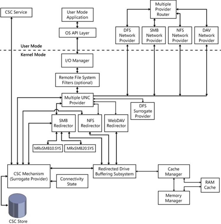
Figure 7-22. MPR and UNC architecture
Surrogate Providers
Prior to Windows Vista, the caching of remote file systems (Offline Files) was implemented inside the SMB mini-redirector, and the DFS-N (Distributed File System Namespace) client was implemented inside MUP. A unified cache was needed, so the remote file system architecture was redesigned for Windows Vista. The DFS-N client was moved into a separate driver component known as a MUP surrogate provider, and Offline Files became a separate driver acting both as a mini-redirector and a surrogate provider. Currently, there are two surrogate providers:
§ Offline Files (%SystemRoot%\System32\Drivers\csc.sys), which determines whether a requested file should be or has been cached locally. Offline Files is hardcoded to be the highest priority surrogate.
§ Distributed File System Client (%SystemRoot%\System32\Drivers\dfsc.sys), which determines whether the path to a requested file needs to be changed (rewritten) to point to another server or share. (The essence of DFS-N is that it collects one or more network shares in the same namespace.) DFSCDFS is hardcoded to be the second highest priority surrogate.
It might appear that having surrogates in the path between MUP and the redirectors would cause a performance penalty, but Offline Files does not process paths that are not enabled for offline access, and after rejecting a path, MUP will not forward Offline Files further I/Os directed at the path. Likewise, DFS does not process non-DFS paths.
The list of surrogates is hardcoded, so MUP does not support the addition of additional surrogates.
Redirector
A network redirector consists of software components installed on a system that support access to various types of resources on remote systems, using various network file protocols. The types of resources a redirector supports depends upon the redirector and the capabilities of the protocol system. Virtually all redirectors support UNC names, which allows the remote sharing of resources such as files, printers, named pipes, and mailslots (although a redirector might opt out of supporting pipes and mailslots, while still supporting printers and files). All redirectors shipping as part of Windows include the following components:
§ A DLL loaded by MPR in user mode, to perform non-file-related operations such as determining the capabilities of the network provider, enumerating remote network resources, logging on to a remote network, and mounting remote network shares.
§ A kernel-mode driver known as a mini-redirector that imports the RDBSS (Redirected Drive Buffering SubSystem) export driver (%SystemRoot%\System32\Drivers\rdbss.sys). The mini-redirector services file I/O requests directed at remote systems.
Some redirectors require one or more of the following optional components:
§ A service process to assist the DLL and possibly store sensitive information or information that is global across client applications using a particular network or share. For example, the Workstation service (running in an SVCHOST process) keeps track of drive-letter to \\server\share mappings.
§ A network protocol driver that implements the legacy Transport Driver Interface (TDI) on its upper edge is required if the redirector uses a network protocol not supplied by Windows. (In essence, this means anything other than TCP/IP.) Such a protocol driver is responsible for implementing communications with the remote system.
§ A service process to assist the redirector. For example, the WebDav redirector forwards file-access operations to the WebClient user-mode service, which in turn issues the actual WebDav network protocol requests using HTTP APIs.
A redirector presents resources that are attached to remote systems as if they were attached to the local system. In Windows, there are no special file I/O APIs required to access resources on a remote system. When accessing a resource, an application generally does not know—nor does it care—whether the resource is located on the local system or on a remote system. The name “redirector” is used because it redirects file system operations to the remote system and returns to the application the responses from the remote system.
All redirectors that ship with Windows are implemented using the mini-redirector architecture, where protocol-specific code is implemented in a mini-redirector driver that imports the RDBSS library. RDBSS is implemented like a class driver, and the mini-redirectors are akin to port drivers. RDBSS registers with MUP by calling FsRtlRegisterUncProviderEx.
When a mini-redirector registers with RDBSS via RxRegisterMiniRdr, RDBSS in turn registers with MUP by calling FsRtlRegisterUncProviderEx. MUP routes requests (IRPs) to RDBSS, which performs processing that is common to all remote file systems, and then issues simplified requests via callback routines that mini-redirectors linked against it have registered. RDBSS provides common functionality such as a data structure and locking model, Cache Manager and Memory Manager integration, and handling of IRPs. This simplifies the implementation of the mini-redirectors, and it vastly reduces the amount of code that needs to be written and debugged.
Because RDBSS integrates with Cache Manager, RDBSS mini-redirectors might not directly see read and write requests on buffered handles (handles opened without specifying the FILE_FLAG_NO_BUFFERING flag to the CreateFile API); changes are cached by the cache manager on the local system until they need to be written back to the remote system. This improves response time, and it saves network bandwidth by aggregating writes and eliminating duplicate reads. RDBSS relies on the mini-redirector to tell it when it is safe to cache data for read and/or write. For example, the SMB mini-redirector uses opportunistic locks (more commonly known as oplocks, which are discussed in Chapter 12 in Part 2) to manage caching. An oplock is a cache coherency mechanism that allows file-system consumers to dynamically alter their caching state for a given file or stream (see Chapter 12 in Part 2 for more information about file system streams), while maintaining cache coherency between multiple concurrent users of a file. If the file (or stream) is not currently opened for read or write by another accessor (either locally or remotely), a client can locally cache reads, writes, and byte range locks. If the file is open by others but is not being written, writes and locks will not be locally cached, but reads can still be cached.
Mini-Redirectors
A mini-redirector implements a protocol necessary to contact a remote system and access its shared resources. The mini-redirector tries to make access to remote resources as transparent as possible to the local client application. For example, if there are network problems, a redirector might retry a request multiple times before it returns an error to the client application.
There are several mini-redirectors included with Windows:
§ RDPDR (Remote Desktop Protocol Device Redirection), which allows access from a Terminal Server system to the client system’s files and printers (%SystemRoot%\System32\Drivers\rdpdr.sys)
§ SMB (Server Message Block), which is the standard remote file system used by Windows (also known as CIFS, or Common Internet File System) (%SystemRoot%\System32\Drivers\MRxSMB.SYS). MRxSMB.SYS will load sub-redirectors, which are covered in the next section.
§ WebDAV (Web Differencing and Versioning), which enables access to files over the HTTP(S) protocol (%SystemRoot%\System32\Drivers\MRxDAV.SYS).
§ MailSlot (part of MRxSMB.SYS). Mailslots are handled very differently from named pipes. The surrogates are not called for I/Os sent to a mailslot, and prefix caching is not used. (All paths having “mailslot” as the share name are targeted directly at the mailslot mini-redirector.) There can be, at most, one mailslot mini-redirector, and it is currently reserved for the SMB redirector.
§ Network File System (NFS) is an optional component that was formerly installed with Services For Unix (SFU) and is now an optional Windows component (available on all Server editions, but only Enterprise and Ultimate editions of Windows client) that can be installed using the Programs and Features control panel. (Click Turn Windows Features On Or Off, and then select Services For NFS.) NFS protocol versions 2 and 3 are supported.
Offline Files, covered in a following section, optionally enables disk caching and offline access to files accessed through the SMB protocol. Offline Files also registers as a MUP surrogate provider.
Server Message Block and Sub-Redirectors
The Server Message Block (SMB) protocol is the primary remote file-access protocol used by Windows clients and servers, and dates back to the 1980s. SMB version 1.0 (generally referred to as just SMB) was designed to operate in a friendly LAN environment, where speeds were typically 10 Mb/s and no one was trying to steal your data. To accomplish many common tasks required a series of synchronous messages between the client and the server. Little thought was given to WANs, because WANs were scarce at the time. In 1996, SMB was submitted to the IETF as the Common Internet File System (CIFS). Microsoft documents the CIFS/SMB protocol in the MS-CIFS and MS-SMB protocol documents.
The SMB 2.0 protocol was released in Windows Vista and Windows Server 2008, and it was a complete redesign of the main remote file protocol for Windows. SMB 2.0 provides a number of improvements over SMB, such as the following:
§ Greatly reduced complexity. The number of opcodes was reduced from over 100 to just 19.
§ Reduced the chattiness of the protocol to make it more suitable for running across WANs, which generally have much longer latencies and lower bandwidth than LANs.
§ Compound requests allow multiple requests to be sent in a single network packet.
§ Pipelining requests allow multiple requests and data to be sent before the answer to a previous request is received (also known as credit-based flow control).
§ Larger reads and writes.
§ Caching of folder and file properties.
§ Improved message-signing algorithm (HMAC SHA-256 replaced MD5).
§ Improved scalability of file sharing.
§ Works well with Network Address Translation (NAT).
§ Support for symbolic links.
Version 2.1 of the SMB protocol (released with Windows 7 and Windows Server 2008/R2) is a minor release (documented in the MS-SMB2 protocol specification). It adds the following improvements:
§ A new opportunistic lock (oplock) leasing model, which allows greater file and handle caching opportunities—without requiring changes to existing applications
§ Support for even larger transmission units (large MTU), from a previous maximum of 64 KB to 1 MB (by default, but configurable up to 8 MB via the registry).
To maintain backward compatibility with SMB servers, an SMB2 client uses the existing SMB connection setup mechanisms, and then advertises that it supports a higher version of the protocol. The SMB mini-redirector contains all the functionality that is common between the different versions of the protocol, with a separate sub-redirector implementing each variant of the SMB protocol. An SMB2 client establishes a connection and sends an SMB negotiate request that contains both the supported SMB and SMB2 dialects. If the server supports SMB2, it responds with an SMB2 negotiate response, and the client hands the connection to the SMB2 sub-redirector. At that point, all messages on the connection are SMB2. If the server does not support SMB2, it responds with an SMB negotiate response, and the client hands the connection to the SMB1 sub-redirector:
§ The common portions are implemented by %SystemRoot%\System32\Drivers\MRxSMB.sys.
§ The SMB 1 protocol is implemented by %SystemRoot%\System32\Drivers\MRxSMB10.sys.
§ The SMB 2 protocol is implemented by %SystemRoot%\System32\Drivers\MRxSMB20.sys.
Distributed File System Namespace
Distributed File System Namespace (DFS-N) is a namespace aggregation and availability feature of Windows. As organizations grow, the number of file servers tends to increase, and users find it increasingly difficult to find the files they need because the files might be spread over a number of different servers with completely unrelated names. DFS-N allows an administrator to create a new file share (also known as a root or namespace) that aggregates multiple file shares, from the same or different servers, into a single namespace. For example, assume the Aura Corporation had the following shares: \\Development\Projects, \\Accounting\FY2012, and \\Marketing\CoolStuff. These shares could be presented to users through a DFS-N namespace \\Aura\Teams containing DFS-N links called \\Aura\Teams\\Aura\Development, \\Aura\Teams\Accounting, and \\Aura\Teams\Marketing. The redirection of a client accessing the path \\Aura\Teams\Marketing to the real share path \\Marketing\CoolStuff is invisible to the user. In this example, \\Marketing\CoolStuff is the link target of \\Aura\Teams\Marketing. Link targets can, in fact, refer to paths below the root of a share like \\Marketing\CoolStuff\Presentations.
Other benefits that DFS-N provides are redundancy and location-aware redirection. Another major capability of DFS is availability, through a feature known as DFS Replication (DFSR). Replication provides two benefits: high availability in case of a failure, and load balancing. As an organization grows geographically, accessing file servers from remote offices with wide area network (WAN) connections might be slow and inefficient. An administrator could create a replicated version of a file server within the remote office, providing high-speed access to the files from the users within the remote office. A DFS-N link, such as \\Aura\Teams\Accounting in the preceding example, might have multiple link targets associated with it—for example, \\AccountingEurope\FY2012 and \\AccountingUS\FY2012. In this case, the DFS-N server returns to the client an ordered list of available target servers and takes into account the location of the client and the target servers (using Active Directory site information) when ordering the list so that the client can access the closest target first. If access to one link target fails, DFS-N tries the next available target, if available. When a DFS-N link has multiple target shares, the targets should normally contain the same data because the client accessing the namespace will access only one of the targets at a time. This can be accomplished using DFS Replication (DFS-R), discussed in the next section. A server-side implementation of DFS-N consists of a Windows service (%SystemRoot%\System32\Dfssvc.exe) and a device driver (%SystemRoot%\System32\Drivers\Dfs.sys). The DFSSVC service is responsible for exporting DFS topology-management interfaces and maintaining the DFS topology in either the registry (on non–Active Directory systems) or Active Directory. The DFS driver performs topology lookups when it receives a client request touching a link so that it can direct the client to the share where the file it is requesting resides.
On the client side, DFS-N support is implemented in a MUP surrogate provider driver (%SystemRoot%\System32\Drivers\Dfsc.sys) and an MPR/WNet provider implemented in %SystemRoot%\System32\Ntlanman.dll. The Distributed File System Client (DFSC) driver is responsible for determining if a UNC path is a DFS namespace, and if so, it translates the specified path into the name of one or more target shares. Communication with DFS-N servers is accomplished using the SMB redirector. The DFS-N client is only part of the I/O path when a file or directory is being created or opened. Once it returns the name of a target share to MUP, DFSC is not involved with subsequent I/O to the file.
The DFS-N protocols are documented in the MS-DFSC and MS-DFSNM protocol documents.
Distributed File System Replication
Distributed File System Replication (DFS-R) provides bandwidth-efficient, asynchronous, multimaster replication of file-system changes between servers. In addition to general-purpose, file-system replication (for example, keeping data on multiple DFS-N link target shares in sync), DFS-R is also used for replicating a domain controller’s \SYSVOL directory, which is where Windows domain controllers store logon scripts and Group Policy files. (Group Policy permits administrators to define usage and security policies for the computers that belong to a domain.) Because DFS-R supports multimaster replication, file-system changes can occur on any server, potentially simultaneously, and DFS-R will automatically handle conflicts and maintain synchronization of the file-system contents.
The fundamental unit of DFS replication is a DFS replicated folder, which is a directory tree whose contents will be synchronized across multiple servers according to an administratively defined schedule and replication topology. Replication schedules allow administrators to restrict replication activity to specific windows of time or restrict the amount of bandwidth that DFS-R will use.
Replication topologies allow administrators to define the network connections between a set of servers (called a replication group). Arbitrary topologies are supported, including common topologies such as ring, star, or mesh. The replication topology configuration is stored in Active Directory. Only directories on NTFS volumes can be replicated because DFS-R relies on the NTFS USN journal to detect changes to the contents of a replicated folder.
DFS-R uses several technologies to conserve network bandwidth, making it well-suited to replication over WANs that might have high latency and low bandwidth. Remote Differential Compression (RDC) allows DFS-R to identify and replicate only those pieces of a file that have changed, rather than the whole file. DFS-R also compresses content before sending it to a remote partner, providing additional bandwidth savings. On Enterprise or Datacenter SKUs, DFS-R makes use of an extended version of RDC called RDC Similarity to provide further bandwidth savings; if content is modified in a replicated folder on server A, and chunks of the modified content are similar to chunks of any file in partner server B’s replicated folder, server B satisfies the similar chunks of the update’s content locally from the similar files, rather than downloading all of the modified content from server A.
New capabilities for DFS-R in Windows Server 2008 R2 include support for clustering and true read-only replicas.
DFS-R is implemented as a Windows service (%SystemRoot%\System32\DfsrS.exe) that uses authenticated RPC with encryption to communicate between instances of itself running on different computers. There is also a WMI interface for configuration and management of the service, a file system minifilter used to protect read-only replicas from modification, and a cluster resource DLL for integration with MSCS. The DFS-R protocol is documented in the MS-FRS2 specification.
Offline Files
Offline Files (also known internally as client-side caching, or CSC) transparently caches files from a remote system (a file server) on the local machine to make the files available when the local machine is not connected to the network. Offline Files caches files for remote files accessed over the SMB protocol. Files can be cached by users by simply right-clicking on a remote file, folder, or drive and selecting Always Available Offline, thus pinning the selected files to the cache. Cached items can be viewed in the Sync Center control panel. Caching also can be specified administratively using Group Policy.
There is a single Offline Files cache on the system, which is shared by all users of the system. All cached files are stored in an ACL-protected directory, which by default is %SystemRoot%\CSC. If you choose, you can encrypt the files in the Offline Files cache (accessed by going to Control Panel, Sync Center, and then clicking Manage Offline Files, clicking on the Encryption tab, and clicking the Encrypt button). Access to the cache is permitted only by using Offline File tools and the IOfflineFilesXxx COM APIs. The easiest way to examine the contents of the cache is to use the Sync Center control panel interface (click Manage Offline Files, and then click the View Your Offline Files button).
Offline Files understands two types of objects:
§ Files. Includes files, folders, and symbolic links. Caching is not done at the NTFS level, so not all file NTFS attributes are cached or are cacheable. Cacheable attributes include the standard Win32 file attributes (metadata), such as the name, ACL, and the contents—only a file’s (unnamed) data stream will be cached.
§ Scope. A scope is the portion of a namespace that corresponds to a physical share. In a DFS namespace, the root of a scope is the object that is pointed to by a DFS link, which can contain additional DFS links to other scopes. If DFS is not being used, a scope and a share are the same thing.
Offline Files does not support complete NTFS semantics for cached files and has the following limitations:
§ Offline Files does not cache alternate data streams, which are therefore not available offline. When online, access to alternate data streams works because I/O requests for streams go directly to the server.
§ Offline Files does not cache Extended Attributes (EAs). An implication of this is that if a file containing EAs is cached and the cached version is modified while the server is offline, any EAs on the server are deleted when changes are written back to the server.
Offline Files consists of the following components, as shown in Figure 7-23:
§ A user-mode agent (%SystemRoot%\System32\cscsvc.dll) running as a service in an SVCHOST process. This service is primarily concerned with maintaining synchronization between the cache and remote file systems. It also implements the COM interfaces used to interact with the Offline Files cache.
§ A remote file system driver (%SystemRoot%\System32\Drivers\csc.sys) that acts as both a MUP surrogate provider and a mini-redirector. This driver is responsible for controlling when I/O requests are sent to the cache or to the remote file system. The driver also implements the local cache, updating the cached data as appropriate based on the I/O requests seen.
§ An Explorer extension DLL (%SystemRoot%\System32\cscui.dll) for selecting which files, folders, or drives to pin in the Offline Files cache, and for displaying icon overlays to identify offline (cached) files. CSCUI links against %SystemRoot%\System32\cscobj.dll, which provides the interface to the Offline Files service.
§ A DLL (%SystemRoot%\System32\cscapi.dll) containing publicly available Win32 APIs for interacting with the Offline Files from applications.
§ An in-process COM object (%SystemRoot%\System32\cscobj.dll) used by application clients of Offline Files COM APIs.
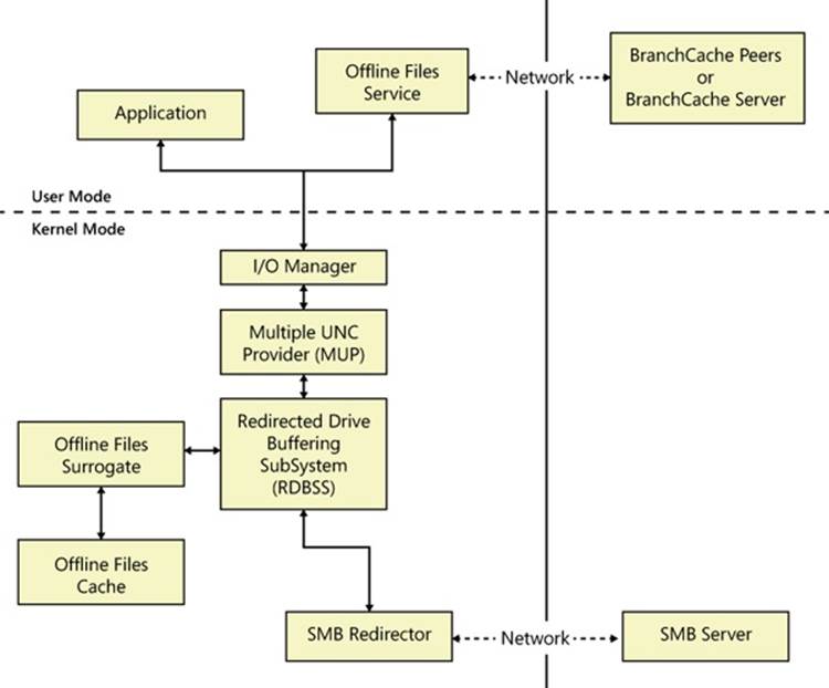
Figure 7-23. Offline Files architecture
Caching Modes
Offline Files has five caching modes. The mode for an object is dependent upon the object’s connection status, which is determined by whether or not the local system has a network connection to the file server.
Online
This is the default mode for objects cached by Offline Files. In this mode, the server is available. The file system metadata operations and write operations flow to the server, and the cache state is updated as required. Read operations are serviced from the cache. When working online, Offline Files attempt to cache data only if the SMB client has been granted at least read-caching privileges from the file server.
Offline (Slow Connection)
To isolate the user from fluctuations in network performance, Offline Files transition into Offline (Slow Connection) mode when the network performance meets the configured slow-link latency or bandwidth thresholds. In Windows 7, a default slow-link latency threshold is configured at 80 milliseconds (ms). The latency and bandwidth thresholds can be controlled via the Group Policy editor (%SystemRoot%\gpedit.msc) via the Configure Slow-Link Mode policy.
When working in this mode, all file-system operations are serviced by the Offline Files cache. The data is synchronized back to the server every six hours by default, but this synchronization frequency can be controlled through Group Policy via the Configure Background Sync policy.
The Offline Files Service periodically checks the network performance of the shares in the Offline Files cache. If the network latency improves to be less than half the configured slow-link latency threshold, the user will transition back to working online.
The slow-link behavior can be controlled via the Group Policy editor (%SystemRoot%\gpedit.msc) as shown in Figure 7-24.
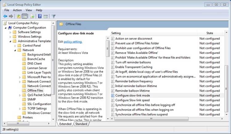
Figure 7-24. Offline Files Group Policy settings
Offline (Working Offline)
The user can force the client to work offline by clicking the Work Offline button in Explorer. When running in this mode, all file-system operations are satisfied from the cache. Periodic background synchronization of the data can be enabled in this mode through the Configure Background Sync policy, but by default they are not enabled. If the user wants to work online again, he must click the Work Online button in Explorer.
Offline (Not Connected)
A cached object is in Offline (Not Connected) mode when the server is not accessible. The transition to offline is transparently satisfied through the Offline Files cache, without the application knowing. When the network connection to the server is re-established, any changes written to the file are synchronized back to the server by the Offline Files agent. If a file is modified on both the client and the remote system while the file was offline, the conflict must be resolved by the user through Sync Center.
Offline (Need to Sync)
When a user transitions back online after making changes to the version of the file in the local cache, the status of this file will be Offline (Need to Sync) until the changes are synchronized back to the server. Offline Files keep the user working offline for the affected files until that synchronization is complete to ensure that the user sees a consistent view of the files, include the changes made while working offline.
Ghosts
When files are selected to be available offline, they must be copied from the server to the client. Until the transfer is complete, not all the files will be visible on the client. This can cause confusion for the user if the server drops offline and the user tries to access a file before it is in the cache. To address this case, Offline Files creates ghosts of the files and directories on the server within the cache as soon as caching is enabled. The ghosts are markers for files and directories that have not been copied and are unavailable in the cache. Explorer displays ghosted files with an overlay on the file’s icon. As the cache is filled, the ghost entries eventually disappear. If the user tries to access a ghosted file and the server is online, the file is copied immediately to the cache and the ghost overlay is removed.
When a subdirectory of a share is pinned into the Offline Files cache, ghosts are also used to provide the user context to the surrounding namespace that is not cached. When offline, the sibling files and directories appear in a ghosted state so that the user does not think that this other content somehow disappeared. When files and directories are ghosted for this purpose, they are neither cached by Offline Files nor are they available while working offline, unless they are explicitly pinned in the Offline Files cache.
Data Security
The goal of Offline Files is to provide the same file-access experience for remote files that the user experience for local files. To achieve that end, Offline Files caches the users and their effective access for each file and directory in the cache. This information is used by the Offline Files driver to enforce the appropriate access on the objects in the cache. Encrypted files using EFS on the server are also encrypted in the cache.
Offline Files caches access for a given user as the data is accessed or synchronized on behalf of that user. For example, if two users, Able and Baker, share a laptop, and user Able marks a file on the server to be available offline, the file is copied to the cache and only Able’s access is cached. If the server drops offline, user Baker would not be able to access the file in the cache; however, when the server is online again, and Baker tries to access the file, Offline Files updates the cache to reflect user Baker’s access, allowing both users to access the file when working offline.
Files protected with EFS remain protected but are encrypted in the security context of the first user to bring the data into the cache. When working offline, only this user will be able to access the data in the cache.
Cache Structure
By default, the root directory for the Offline Files cache is located in %SystemRoot%\CSC and is protected with a DACL that grants Administrators full control of the directory and everyone else read, Read & Execute, and List Folder Contents access. As shown in Figure 7-25, beneath the root directory is a subdirectory with a name equal to the current version of the database schema (currently, 2.0.6) and a security descriptor specifying an owner SID of S-1-5-12, which is used to indicate it is owned by restricted code and cannot be accessed by anyone other than the Offline Files service. This security descriptor is inherited by all files and subdirectories beneath the schema version directory.
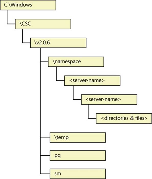
Figure 7-25. Default Offline Files directory structure
In the schema version directory are two files and two directories. The files consist of the Priority Queue (pq) and SID Map (sm) databases. The Priority Queue is a database that tracks the usage of the files within the cache and orders them from most recently used to least recently used. The Offline Files agent threads walk the queue tail to head when pushing files out of the cache when the cache’s disk quota has been exceeded. Within the Offline Files cache, an internal user ID is used to represent a user when storing that user’s access. The SID Map is used to map these internal user IDs to SIDs. This becomes important when the server is offline and Offline Files must validate the user’s access itself.
The namespace directory is the root of the cache and contains a directory for each server that Offline Files is caching. The temp directory is for encryption and is also used as a temporary location for files that are removed from the namespace before they are deleted. The temp directory is used as a scratch area by Offline Files.
For every file in the Offline Files cache, Offline Files adds a sparse NTFS alternate data stream named CscBitmapStream, which contains a bitmap indicating which pages of the file have been modified while the file was “offline” (server not reachable). Each bit in the bitmap represents a 4-KB page within the file. This bitmap is not created until the first offline write to a file. Writes that extend the file are not included in the bitmap. If the file is truncated while offline, the bitmap is also truncated to match the new length of the file. When the server is next online, only the changed pages are written to the server.
BranchCache
BranchCache is a generalized content-caching mechanism designed to reduce network bandwidth, especially over WANs. The name BranchCache comes from the concept of branch offices within a company connecting to the company’s centralized servers via WAN links, which are typically hundreds of times slower than LAN links and caching content used by computers in the branch office within that branch office. Moving the content cache to the branch office drastically reduces the time to access the content because the data does not have to traverse the WAN.
Unlike Offline Files, which caches only files, BranchCache caches content, which is anything that can be identified by a URL, such as files, web pages, an HTTP video stream, or even a blob accessed from a database or cloud service.
BranchCache does not access the files in the CSC cache, because CSC is a client of BranchCache. Instead, Offline Files uses BranchCache to populate its own cache.
A variety of protocols make use of BranchCache, including the following ones:
§ Server Message Block (SMB). Used to access files on file servers
§ HTTP(S). Web pages, video streams, and other content identified by a URL
§ Background Intelligent Transfer Service (BITS). Used to transfer files, and runs over HTTP/TLS 1.1
Figure 7-26 depicts the BranchCache architecture.
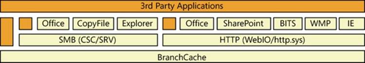
Figure 7-26. BranchCache architecture
BranchCache’s operation is transparent to the applications accessing the content being cached, as shown in Figure 7-26. When BranchCache is enabled on a client, a request made by that client to a content server carries headers/metadata (the exact mechanism depends upon the protocol used) to let the remote content server know that the client has BranchCache enabled. In this case, the content server returns content information (CI) describing that content, rather than the requested content. The CI contains hashes of all the segments and blocks in which the content is chunked. (This is covered in more detail later.) The client uses the CI for retrieving part, or all, of the content from the local BranchCache. If any part of the content is not available locally, the client goes back to the remote content server to retrieve the data that was not present in the local BranchCache and, once the data is retrieved, offers the missing data to the local BranchCache so that the same data can be served to other clients in the future.
BranchCache operates in two caching modes, as shown in Figure 7-27:
§ Hosted Cache. A single server in a branch office (running Windows Server 2008/R2, or later), with the BranchCache feature enabled, contains the entire content cache for all BranchCache-enabled systems within that branch office.
§ Distributed Cache. Instead of a hosted cache server caching content for the remote office, the clients within the remote office cache the content files themselves. The cache is spread across all the clients on the same subnet. There is no effort to evenly distribute the contents of the cache among peers within a branch office. In general, until the maximum local cache size is reached, each client has a copy of all the content it has accessed (resulting in content being duplicated throughout the distributed cache). This is desirable because it adds redundancy and some resiliency to the cache, especially when clients join and leave the branch office network frequently, as is often the case when the users are working on laptops. The distributed cache is implemented using peer-to-peer networking, using the Web Services Discovery (WS-D) multicast protocol to locate which client has the content in its cache, with a 300-millisecond timeout.
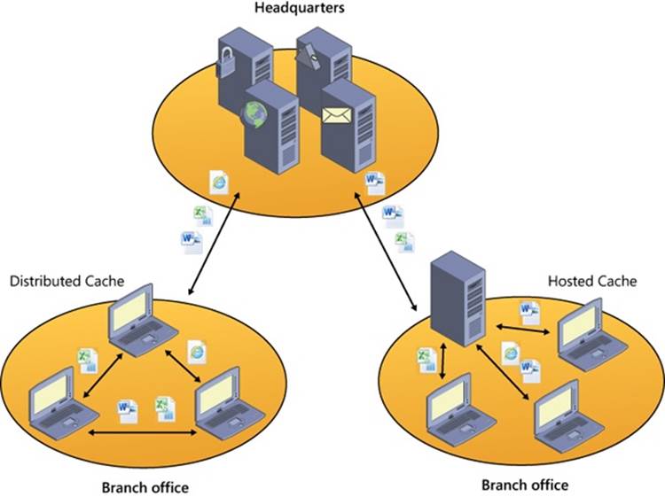
Figure 7-27. Types of BranchCache caching
BranchCache is fully compatible with end-to-end encryption, such as IPsec. Just like with CSC, Windows’ existing security mechanisms are used to ensure that access to cached content operates the same way that it would if the content were not cached.
BranchCache is similar to Offline Files, but it differs in several important ways. The most important of which is that content in the BranchCache is not available if the WAN is down. This is because the content is identified by a hash list generated and stored on the server, which the client uses to locate the cached content within the BranchCache (distributed or hosted). Some BranchCache features the following behaviors:
§ Data transfer uses AES encryption.
§ For content that is not file-based, BranchCache caches only content that is larger than 64 KB. (This can be changed by editing the registry value HKLM\System\CurrentControlSet\Services\PeerDistKM\Parameters\MinContentLength on the server.)
Caching Modes
BranchCache maintains two different local caches on each BranchCache-enabled system (which can be BranchCache content servers on one side of the WAN link, and BranchCache clients and BranchCache hosted cache servers on other side):
§ The publication cache stores content information metadata for content published using the BranchCache Server APIs (PeerDistServerXxx). The content information structure contains hashes of the various segments and blocks in which BranchCache breaks up the content into chunks, along with the secret needed to generate public and private content identifiers and the encryption key.
§ Publishing is usually thought of as a server-side operation, though any BranchCache client can publish content. With regard to publishing, BranchCache offers two different approaches to its client applications/protocols for generating/managing/storing BranchCache content information metadata:
§ An application and/or protocol that uses BranchCache acceleration can ask BranchCache to store content information metadata on its behalf (in the BranchCache publication cache), allowing BranchCache to manage the lifetime of that metadata according to rules, timelines, and limits shared across multiple applications using BranchCache. This is achieved by publishing via the PeerDistServerXxx APIs, and it is what the HTTP-BranchCache and BITS-BranchCache integrations do.
§ Alternatively, an application/protocol that wants to use BranchCache acceleration can ask BranchCache to generate only content information metadata without storing it, and instead simply return the metadata to the application or protocols. In this case, the application or protocol has to implement its own way to store or manage that metadata. This is what the SMB-BranchCache integrations does.
In both cases, the protocol integrated with BranchCache or the application using BranchCache directly is responsible for transporting that content information metadata through the WAN link from the publishing content server to the clients in the remote branches. BranchCache does not have, or control, a data channel crossing the WAN link. The transport of content information metadata is intentionally left to the protocol or application using BranchCache acceleration, so that the metadata can be transported with the same level of security, authentication, and authorization that would have been used for retrieving the actual content when BranchCache is not used. This is consistent with the fact that, from a security standpoint, owning a copy of the BranchCache content information for a given content is equivalent to owning the entire content and therefore being authorized to retrieve a copy of it from other BranchCache entities (clients, hosted cache servers, or third-party implementations).
The publication cache does not store any actual data of the published content; it stores only content information metadata. Publications tend to last for long periods of time, though the actual length of time is determined by the application that publishes the content. By default, the publication cache is constrained to consume no more than one percent of the volume on which it is located, which is specified by %SystemRoot%\ServiceProfiles\NetworkService\AppData\Local\PeerDistPub. The size and location of the publication cache can be changed using NetSh:
§ netsh branchcache set publicationcache directory=C:\PublicationCacheFolder
§ netsh branchcache set publicationcachesize size=20 percent=TRUE
§ The republication cache contains both metadata (but no secrets) and actual data (chunked in segments and blocks) for the BranchCache content retrieved by the local BranchCache client. It is stored with the purpose of making those chunks of content available to other BranchCache clients. Republished content is stored for up to 28 days, but it can be flushed out earlier if the republication cache has reached its limit and space is needed for newer content to be republished. By default, the republication cache is constrained to consume no more than five percent of the volume on which it is located, which is by specified by %SystemRoot%\ServiceProfiles\NetworkService\AppData\Local\PeerDistRepub. The location and the size of the republication cache can be changed using NetSh:
§ netsh branchcache set localcache directory=C:\BranchCache\Localcache
§ netsh branchcache set localcache size=20 percent=TRUE
BranchCache attempts to persist the republication cache across system reboots through the use of an index file that contains the database of segment descriptors. When the system reboots, BranchCache validates the general integrity of the republication cache by checking that it was properly closed. If the republication cache fails this consistency check, it is discarded. The publication cache is not persisted across reboots. The private SMB-BranchCache publication cache needs no explicit persistence; persistence comes for free, as a result of the SMB-BranchCache integration (which was covered previously) and the fact that with the SMB all published content is actual files. The hashes are validated before access to the files in the cache is allowed.
Configuration
BranchCache can be configured using the Local Security Group Policy editor as shown in Figure 7-28, using the network shell (NetSh) as shown in Figure 7-29, or as part of Group Policy pushed by an administrator (within a domain).
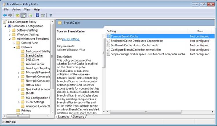
Figure 7-28. Configuring BranchCache using the Group Policy editor
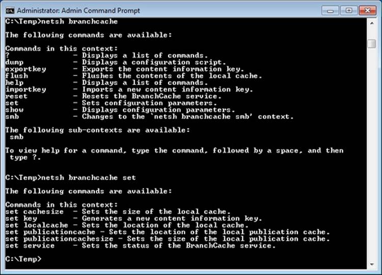
Figure 7-29. Configuring BranchCache using the network shell
§ BranchCache Implementationservice in %SystemRoot%\PeerDistSvc.dll. This service starts when the BranchCache is enabled on both clients and servers, and it interacts with the kernel-mode components (drivers).
§ HTTP extension driver in %SystemRoot%\System32\Drivers\PeerDistKM.sys. This driver registers with the Network Module Registrar (NMR) as a client of the http.sys driver and examines all HTTP packets going into and out of the system. It adds files to the cache and retrieves cached content information for published content from the BranchCache service, rather than sending the request to the web server.
§ BranchCache APIs (PeerDistXxx) are exported by %SystemRoot%\System32\PeerDist.dll, which uses LRPC/ALPC to communicate with the BranchCache service.
§ The BranchCache HTTP transport in %SystemRoot%\System32\PeerDistHttpTrans.dll implements the transport on top of which the Peer Content Caching and Retrieval: Retrieval Protocol [MS-PCCRR] exchanges data between BranchCache clients and/or hosted cache servers. Each MS-PCCRR message is encapsulated in a simple transport message, which in turn, is sent over an HTTP request.
§ The Web Services Discovery Provider in %SystemRoot%\System32\PeerDistWSDDiscoProv.dll implements the WS-D protocol to discover which clients on the LAN are caching a particular file (or part of a file).
§ The BranchCache Network Shell Helper in %SystemRoot%\System32\PeerDistSh.dll is an extension to the Network Shell (%SystemRoot%\System32\Netsh.exe) application that provides users with a means of monitoring and configuring the BranchCache service. Network Shell helper DLLs are installed by adding a string value to HKEY_LOCAL_MACHINE\SOFTWARE\Microsoft\NetSh, which provides the Network Shell with the path to the helper DLL.
§ A standalone variant of all the BranchCache APIs are implemented in %SystemRoot%\System32\PeerDistHashPeerDistHash.dll (only present on Windows Server systems), which contains all of the BranchCache APIs and functionality and does not require the use of the BranchCache service. This component is designed for use by other Windows features that are tightly integrated with BranchCache, such as the SMB Groveler, which generates the hashes on the server.
§ Hash groveler service in %SystemRoot%\System32\smbhash.exe (only on Windows Server systems). The groveler runs on the file or web server and generates hashes when clients request a hash list. The groveler monitors a given namespace or share and ensures that the BranchCache hashes are updated for all files within that namespace. All groveler I/O runs at low I/O priority so as not to interfere with the normal operation of the system.
BranchCache uses the following protocols, which are documented at www.microsoft.com:
Peer Content Caching and Retrieval: Content Identification, as defined in [MS-PCCRC], defines the content information structures previously described. Peer Content Caching and Retrieval: Discovery Protocol, as defined in [MS-PCCRD], specifies a multicast to discover and locate services based on the Web Services Dynamic Discovery (WS-Discovery) protocol [WS-Discovery]. There are two modes of operations in WS-Discovery: client-initiated probes and service-initiated announcements. Both are sent through IP multicast to a predefined group. The primary role in the Content Caching and Retrieval System is Content Discovery.
§ Peer Content Caching and Retrieval: Retrieval Protocol, as defined in [MS-PCCRR], specifies the messages that are necessary for querying peer-role servers or a hosted cache server for the availability of certain content, and for retrieving the content. The primary role in the Content Caching and Retrieval System is Content Retrieval.
§ Peer Content Caching and Retrieval: Hosted Cache Protocol, as defined in [MS-PCHC], specifies an HTTPS-based mechanism for clients to notify a hosted cache server regarding the availability of content and for a hosted cache server to indicate interest in the content. The primary role in the Content Caching and Retrieval System is Content Notification.
§ Peer Content Caching and Retrieval: Hypertext Transfer Protocol (HTTP) Extensions, as defined in [MS-PCCRTP], specifies a content encoding known as PeerDist that is used by an HTTP/1.1 client and an HTTP/1.1 server to communicate content to each other. The primary role in the Content Caching and Retrieval System is Metadata (Hash) Retrieval.
§ Server Message Block (SMB) Version 2.1 Protocol, as defined in [MS-SMB2]. Version 2.1 of this protocol has enhancements for the detection of content caching-enabled shares and retrieval of metadata related to content caching. The primary role in the Content Caching and Retrieval System is Metadata (Hash) Retrieval.
Supporting SMB-BranchCache integration requires the following changes on both the clients and servers. On the client, the functionality of the existing client-side caching (CSC) components were extended. On the server, the SMB Server Driver (srv2.sys) was extended to support hash list retrieval from the server, and a new service was added, the SMB Hash Generation Service (also known as the Groveler), to manage the generation, updating, and deletion of hashes for content on an SMB share.
BranchCache Optimized Application Retrieval: SMB Sequence
The following sequence describes how content that is cached by BranchCache is delivered to an application without requiring any changes to the application, as shown in Figure 7-30. This sequence refers to the case when the channel/protocol of choice for that application is SMB—for example, the application opens the file from the remote share with CreateFile (or something that calls CreateFile, such as fopen) and reads from the file. If the application decides to retrieve the data via an HTTP request (backed by either WinHTTP or WinInet), the sequence is very different, but it is still a sequence completely transparent to the application.
BranchCache and SMB are integrated through the Offline Files component in Windows. The Offline Files service opportunistically tries to prefetch files accessed via SMB to optimize network usage and user experience on the client side. The offline files driver might temporarily delay the application’s read to give the prefetch from BranchCache an opportunity to stay ahead of the application’s read position. This delay is calculated based on the measured latency to the file server.
Data retrieval begins with an application reading data from a file on a remote SMB share. When Offline Files is enabled on the client and BranchCache is not enabled, the application’s read request flow through the offline files driver to the SMB server. When both offline files and BranchCache are enabled on the client, the following steps occur:
1. The offline files driver intercepts the read I/O request and determines whether the following specific conditions have been met to initiate prefetching the file:
a. The data is not already stored in the offline files cache. If the data is already present, the application’s read will be satisfied by this data without making any data requests to the file server.
b. The latency to the server (as observed by the client so far) is above the configured threshold.
c. BranchCache hash generation is enabled on the file share.
d. The target file size is at least 64 KB.
e. The read is beyond the first 64 KB of the file.
2. If the preceding conditions are met, the offline files driver notifies the offline files service to start prefetching the file.
3. The offline files service then retrieves the content information from the file server. If the server has the up-to-date content information for the specified file, it returns it to the client. If there is no content information for the specified file or if it is out of date, the SMB hash-generation service on the file server will be requested to generate new content information for this file, and no content information is returned to the client, causing offline files to skip BranchCache retrieval for this file.
4. If content information is retrieved from the file server, the offline files service then uses that information to attempt to retrieve data from BranchCache.
5. BranchCache attempts to retrieve the data either from peers or the hosted cache (depending on the configuration). If data is found, it is returned to the offline files service; otherwise, an error is returned.
6. If data is found in BranchCache, the data is written to the offline files cache and the prefetch thread continues to attempt to retrieve data from BranchCache until it has retrieved up to 8 MB of data or it fails to retrieve data.
7. When the application’s read operation is allowed to proceed, it attempts to read the data from the offline files cache, which is prepopulated by data from BranchCache if the prefetch thread successfully retrieved data. Otherwise, the application’s read is allowed to flow to the server to retrieve data. Data retrieved from the file server is then cached in the offline files cache for later publication to BranchCache.
8. When the Offline Files Service is requested to prefetch data from BranchCache, it also attempts to publish any data to BranchCache for the file from the offline files cache. File data is stored in the offline files cache until the offline files cache needs to reclaim space for newer files. The same data is also stored in BranchCache’s republication cache so that it can be shared with other BranchCache clients and across different protocols/applications integrated with BranchCache.
If the client accesses the same content again (after closing the file and opening it again) and the content has not been changed on the server, the application will be able to retrieve the data from the Offline Files cache without doing the BranchCache lookup. This is called transparent caching.
If the requested data cannot be found through BranchCache, once it is retrieved from the SMB server it will be republished to the BranchCache for access by other clients. (These steps are not shown in Figure 7-30.)
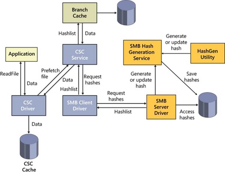
Figure 7-30. BranchCache request flows
BranchCache Optimized Application Retrieval: HTTP Sequence
The following sequence describes how content that is cached by BranchCache is delivered to an application without requiring any changes to the application. This sequence covers the case when the channel/protocol of choice for that application is HTTP, for example the application retrieves the content via an HTTP request based on either WinInet or WinHTTP APIs.
BranchCache and HTTP are tightly integrated, both in terms of HTTP.sys on the server side and WinInet and WinHTTP on the client side. In contrast with the SMB-BranchCache integration, when BranchCache is enabled on both client and server, an application’s HTTP requests are always stalled, waiting for BranchCache retrievals. The HTTP-BranchCache integration is focuses on minimizing the usage of the WAN’s bandwidth (even when the WAN happens to be very fast and has very low latency), and all the data that can be retrieved via BranchCache will be transferred via BranchCache.
1. Data retrieval begins with an application issuing an HTTP Request.
2. When BranchCache is enabled on the client, the HTTP client stack (either WinInet or WinHTTP) adds headers to the request indicating that the client is capable of understanding the PeerDist HTTP encoding (as defined in [MS-PCCRTP]).
3. The HTTP client stack sends the request to the remote content server, typically across the WAN link.
4. The kernel-mode HTTP driver (HTTP.sys) receives the request on the content server. If BranchCache is enabled on that server, HTTP.sys forwards a copy of the request to the BranchCache HTTP extension driver (PeerDistKM.sys), which keeps track of the request and retrieves content information for that content (identified by its URL and content tags) from the BranchCache service.
5. The kernel-mode HTTP driver delivers the HTTP request to the associated web server in user mode (typically, IIS or a web service) and waits for a response.
6. The HTTP server authenticates and authorizes the client, it generates the response accordingly, and it starts streaming the response down to HTTP.sys.
7. Because BranchCache is enabled, HTTP.sys redirects the response through PeerDistKM.sys.
8. If the content information for that HTTP content is not available (or not yet available) or if the content tags do not match, the following steps occur:
a. PeerDistKM.sys sends a copy of the response stream to the BranchCache service for publication so that the next request for the same URL will find the content information.
b. It allows the response stream to go back to HTTP.sys unchanged.
c. HTTP.sys sends out the response with actual data in it and no BranchCache metadata.
9. If, instead, the content information for that HTTP content is available and, based on content tags, it is found to be up to date with the content returned, the following steps occur:
a. PeerDistKM.sys replaces the body of the response with the content information describing it in BranchCache terms.
b. It modifies the response headers adding that the response is now PeerDist-encoded.
c. It returns the modified (and, in general, much shorter) response stream to HTTP.sys.
d. HTTP.sys sends out the modified response, containing only BranchCache content information metadata, but not any actual content data.
10.The response is received on the client side. If the response contains BranchCache content information, the HTTP client stack passes that metadata to the BranchCache service, and it starts serving the first application read for the actual contents of that response by asking BranchCache to retrieve the content data associated with the size of that first read.
11.BranchCache retrieves that data from the local republication cache (if available), or it retrieves a superset including the requested data either from other BranchCache clients in the LAN or from the hosted cache server (depending on the configuration).
12.If any of the requested data is missing, BranchCache signals to the HTTP stack the range of missing data, and the HTTP stack issues a range request back to the remote server for the missing data (or a superset including it).
13.Once all the data is reassembled for the specific application read, it is returned to the application in a way completely transparent to the application.
14.The last three steps are repeated until all the application’s reads on the HTTP response in question are completed.
Name Resolution
Name resolution is the process by which a character-based name, such as www.microsoft.com or Mycomputer, is translated into a numeric address, such as 192.168.1.1, that the network protocol stack can recognize. This section describes the three TCP/IP-related name resolution protocols provided by Windows: Domain Name System (DNS), Windows Internet Name Service (WINS), and Peer Name Resolution Protocol (PNRP).
Domain Name System
Domain Name System (DNS) is the standard (RFC 1035, et al.) by which Internet names (such as www.microsoft.com) are translated to their corresponding IP addresses. A network application that wants to resolve a DNS name to an IP address sends a DNS lookup request using the UDP/IP protocol (TCP/IP is used for requests whose response size exceeds 512 bytes) to a DNS server. DNS servers implement a distributed database of name/IP address pairs that are used to perform translations, and each server maintains the translations for a particular zone. Describing the details of DNS is outside the scope of this book, but DNS is the foundation of naming in Windows and so it is the primary Windows name resolution protocol.
The Windows DNS server is implemented as a Windows service (%SystemRoot%\System32\Dns.exe) that is included in server versions of Windows. Standard DNS server implementation relies on a text file as the translation database, but the Windows DNS server can be configured to store zone information in Active Directory.
Peer Name Resolution Protocol
The Peer Name Resolution Protocol (PNRP) is a distributed peer-to-peer protocol that allows for dynamic name resolution and publication exclusively across IPv6 networks. It allows Internet-connected devices to publish peer names and their associated IPv6 address, as well as optional information. Other devices will then resolve the peer name, retrieve the IPv6 address, and establish a connection.
PNRP offers significant advantages over DNS, mainly by being distributed, which means that it is essentially serverless (other than for early bootstrapping), can scale to potentially millions of names, and is fault tolerant and bottleneck free. Because it includes secure name publication services, changes to name records can be performed from any system. DNS generally requires contacting a DNS server administrator to perform updates. PNRP name updates also occur in real time, making it appropriate for highly mobile devices, whereas DNS caches results. Finally, PNRP allows for naming more than just computers and services by allowing extended information to be published with name records. The specification for the Peer Name Resolution Protocol [MS-PNRP] can be found at www.microsoft.com.
Windows exposes PNRP via a PNRP API for applications and services, as well as by extending the getaddrinfo Winsock API described earlier in the chapter to perform resolution of PNRP IDs (described next) when an address includes the reserved .pnrp.net domain suffix.
PNRP peer names (also called P2P IDs) are made up of two components:
§ Authority. For secure clients (which have their name records signed by a certifying authority), the authority is identified by a SHA-1 hash of an associated public key, and for unsecured clients, it is zero. If a client is secure, PNRP validates the name record before publishing it.
§ Classifier. The classifier uses a simple string to identify a service provided by a peer, which allows multiple services to be provided by the same device.
To create a PNRP ID, PNRP hashes the P2P ID and combines it with a unique 128-bit ID called the service location, as shown in Figure 7-31. The service location identifies different instances of the same P2P ID in the same cloud. (PNRP uses two clouds: a global cloud, which corresponds to all IPv6 addresses on the Internet, and the link-local cloud, which corresponds to IPv6 addresses with the fe80::/10 prefix and is analogous to an IPv4 subnet.)
Figure 7-31. PNRP ID generation
PNRP Resolution and Publication
PNRP name resolution occurs in two phases:
§ Endpoint determination. In this phase, the requesting peer determines the IPv6 address associated with the peer responsible for publishing the PNRP ID of the desired service.
§ PNRP ID resolution. In this phase, once the requesting peer has located and confirmed the availability of the peer associated with the IPv6 address, it sends a PNRP request message for the PNRP ID of the service being requested. The peer providing the service replies to confirm the PNRP ID and can supply a comment and up to 4 KB of additional data, such as context information related to the service.
During the first phase, PNRP iterates over nodes while locating the publishing node, such that the node performing name resolution will be responsible for contacting nodes that are successively closer to the desired PNRP ID. Each iteration works as follows: Once a peer receives a request message, it performs a lookup in its cache for the requested PNRP ID. If a match is found, the request message is sent directly; otherwise, it is sent to the next closest PNRP ID (by seeing how much of the ID matches).
When a node receives a request message for which it cannot find a PNRP ID, it checks the distance of any other IDs in the cache to the target ID. If it finds a node that is closer, the requested node sends a reply to the requesting node, where the reply contains the IPv6 address of the peer that most closely matches the target PNRP ID. The requesting node can then use the IPv6 address to send another query to that address’ node. If no node is closer, the requesting node is notified, and that node sends the request to the next closest node. Assuming PNRP IDs of 200, 350, 450, 500, and 800, Figure 7-32 depicts a possible endpoint determination phase for an example in which peer A is trying to find the endpoint for PNRP 800 (peer E).
To publish its PNRP ID(s), a peer first sends PNRP publication messages to its closest neighbors (entries in its cache that have IDs that are in the lowest levels) to seed their caches. It then randomly chooses nodes in the cloud that are not neighbors and sends them PNRP name resolution requests for its own PNRP ID. Through a mechanism described earlier, the endpoint determination phase results in the seeding of the PNRP ID across the caches of the random nodes that were chosen in the cloud.
Figure 7-32. Example of PNRP name resolution
Location and Topology
Today, networked computers often move between networks that require different configuration settings—for example, a corporate LAN and a home-based wireless network. Windows includes the Network Location Awareness (NLA) service to enable the dynamic configuration of network applications and settings based on location, and Link-Layer Topology Discovery (LLTD) to enable the intelligent discovery and mapping of networked devices.
Network Location Awareness
The Network Location Awareness (NLA) service provider is implemented as a Winsock Namespace Provider (NSP) and provides the necessary framework for allowing computers and devices that move across different networks to select the most appropriate configuration settings. For example, an application taking advantage of NLA can detect when the user moves from a high-speed LAN to a high-latency wireless network and fine-tune its bandwidth use appropriately. NLA can also detect when a home computer on a LAN might also have a secondary VPN connection to the office and select the proper configuration options.
Instead of having developers rely on manual network interface information to figure out the type of network, and the IP addresses or DNS names associated with them, NLA provides a standardized query API for enumerating all the local network attachment information and correlating it with network interface information. The NLA API also includes notifications that enable applications to respond to changes when they occur. NLA provides applications two pieces of location information:
§ Logical network identity. This identity is based on the logical network’s DNS domain name. If one does not exist, NLA uses custom static information stored in the registry together with the network’s subnet address as the identity.
§ Logical network interfaces. For each network that a device is attached to, NLA creates an adapter name that identifies interfaces such as NICs or RAS connections in a unique fashion. Applications use adapter names with the IP Helper API (%SystemRoot%\System32\iphlpapi.dll) to query interface information and characteristics.
Each logical network is implemented as a service class with an associated GUID and properties. NLA creates instances of that service class when it returns information about a logical network. Service classes are schemas that describe a namespace; they define the name, identifier, and namespace-specific information that is common to all instances. These classes are then used in combination with the WSALookupServiceXxx APIs when performing name resolution.
The best way to get network location information programmatically is to use the Network List Manager (NLM) APIs—for example INetworkListManager, INetwork, IEnumNetworks, INetworkEvents, and so on.
Network Connectivity Status Indicator
Network Connectivity Status Indicator (NCSI) determines in real time the connectivity level of network connections on a system. It is loaded by the NLA service and functions solely as an information provider for NLA. NLA enables network-interacting programs to change their behavior based on how the computer is connected to the network. NCSI does not register as a client of NLA, but it does receive certain private notifications directly from it. NCSI detects local vs. Internet connectivity, hotspot networks, and corporate connectivity detection and level.
The connectivity level of a network connection is assessed and is based on whether or not the system has access to the Internet and to network devices such as the default gateway, DNS servers, and web proxy servers. This network connectivity information is used by various applications such as the Networking Tray Icon, Mini Map, Network Connection Wizard, Windows Media Center, DirectAccess, Windows Update, and Outlook. NCSI information is displayed in the tray as an overlay on the network icon. Most of NCSI’s activity is disabled if a user is not logged in.
NCSI performs the primary tasks described in the following sections.
Passive Poll
Every five seconds (configurable in the registry), NCSI activates to perform its general processing. The main purpose of this action is to query the network stack using the Network Storage Interface (NSI), and looks for:
1. Evidence that some traffic has been received. NSI returns packet counts for each network interface. If any packets have been received on an interface, that interface will have at least local connectivity.
2. Evidence that traffic has been received from either the Internet or corporate network. This is a little more complex and is determined by calculating the average number of hops a packet takes to depart from a system’s local ISP network (in a home/nondomain environment) or intranet (in a corporate environment). NSI returns the largest hop count seen since the last time the hop counts were requested. If this value exceeds the average for a given IP family (for example, IPv4 vs. IPv6) on a given interface, that interface has internet connectivity.
3. Evidence that the host is communicating with a web proxy. The IP addresses for web proxies will have been identified using Web Proxy AutoDetect (WPAD), or DNS, and proxies configured manually through Internet control panel. NSI returns details of the current TCP paths from the network stack. If this is a new path to a proxy, that interface has internet connectivity.
4. Evidence that an IPSEC Security Association (SA) has been established between the system and a host that has an IPv6 address matching the corporate network prefix defined in the registry. (This is passive corporate connectivity detection.)
5. Evidence that there is a reachable path reported by NSI to a host with an IPv6 prefix matching the corporate network prefix in the registry. The interface is marked with corporate connectivity.
In addition to handling the NSI queries, the passive poll is also used by NCSI to carry out most time-based processing. If there are no networks connected, NCSI continues to poll, but stops polling three polling periods after the last data is received.
Network Change Monitoring
NCSI has to be aware of changes to the configuration of interfaces on the system. This is handled by two event monitors that watch for NSI interface change notifications and DHCP status change notifications.
When NCSI detects that the network has changed, it records the current time in a data structure associated with each interface. The passive poll task queries this value and, if it is older than 15 seconds, it will perform an active probe. The 15-second delay (for example, three poll periods have elapsed) is used to re-evaluate the Internet connectivity state if it has seen one or more unreachable paths.
NCSI registers for DHCP events and responds to them immediately (that is, there is no dampening that happens). If in that callback, DHCP reports that an interface is stable, an active probe is queued for that interface.
Registry Change Monitoring
NCSI monitors two parent keys in the registry for any changes to themselves or their children using the registry change notification API. Any changes trigger NCSI to reload all values under each key:
§ HKLM\System\CurrentControlSet\Services\NlaSvc\Parameters\Internet
§ HKLM\SOFTWARE\Policies\Microsoft\Windows\NetworkConnectivityStatusIndicator
Active Probe
NCSI has two mechanisms for actively testing an interface to determine whether it has Internet connectivity, both of which are configurable (and can be disabled) using the registry keys.
The first time an active probe is performed on an interface, it will be a web probe. This consists of an attempt to download the file http://www.msftncsi.com/ncsi.txt,_and it compares the contents of that file with the expected value of “Microsoft NCSI”. If the comparison succeeds, the active probe is considered successful.
If NCSI has detected proxy servers, it checks to see if the interface being probed is the best interface over which to reach the first proxy server. If so, it applies the proxy settings to the HTTP request. Otherwise, it first tries without the proxy settings, only applying them and making a second attempt if the first failed with name resolution failure. This is to support multihomed scenarios, where one interface is connected via proxy and the interface being probed is not.
If an active probe succeeds, either the IPv4 or IPv6 Internet state will be brought to internet connectivity. Because NCSI does not know whether the request was satisfied using IPv4 or IPv6 connectivity, it makes a guess based on the existence of default gateways for each address family, with IPv4 being selected if an exact determination cannot be made.
The next time an active probe is to be performed, if the hardware address of the default gateway is already in the list of known proxy-less gateways, a DNS probe is performed instead of a web probe. This is an optimization that produces quicker results. A DNS probe performs a simple DNS lookup for the name listed in the registry, with the default being dns.msftncsi.com.
HTTP probe behavior changes in multihomed scenarios when a proxy is detected. When an active probe is executed on an interface, a check is made whether or not that interface is preferred by the network stack to reach the first proxy server address. If so, the web probe is continued as normal. If not, the web probe is first attempted without the use of the proxy. If that fails because the name could not be resolved via DNS, NCSI concludes it must be behind the proxy after all and applies the proxy server settings and retries the probe.
The content retrieved by the HTTP request is compared to known content in the registry. If the content does not match, NCSI assumes that the interface is connected to a hotspot network (which has rerouted the HTTP request to a login page). It then uses the Network List Manager (NLM) APIs to send a message to the PNIDUI (%SystemRoot%\System32\pnidui.dll) Shell Service Object (SSO), which then displays a balloon to indicate to the user that she needs to log in before connecting to the Internet. The gateway MAC address is also recorded in a known hotspot gateway list for proxy detection optimization later.
NSCI can be configured via Group Policy, as shown in Figure 7-33, or via the registry.
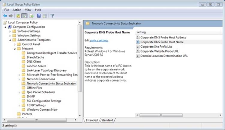
Figure 7-33. NCSI parameters in the Group Policy editor
Link-Layer Topology Discovery
The Link-Layer Topology Discovery (LLTD) protocol operates over both wired and wireless networks and enables applications to discover the topology of a network. For example, the Network Map functionality in Windows uses LLTD to draw the local network topology for the connected devices that support the LLTD protocol. Additionally, LLTD supports Quality of Service (QoS) extensions, which allow applications to diagnose network problems such as low signal strength on a wireless network and bandwidth constraints on home networks. Because it operates on the OSI data-link layer, LLTD works only on a single LAN or subnet and cannot cross routers, but its capabilities make it suitable for most home and small-office networks. The specification for the Link-Layer Topology Discovery protocol [MS-LLTD] can be found atwww.microsoft.com.
The LLTD Mapper I/O and the LLTD Responder components implement LLTD. The former is responsible for the discovery process and for generating network maps. Because it uses a protocol different from IP, the LLTD Mapper uses NDIS APIs to directly send commands to the network via the network adapter. The LLTD Responder listens for and responds to discovery commands with information about the computer. As mentioned earlier, only devices that have a responder are shown in the network map.
Protocol Drivers
Network drivers take high-level I/O requests and translate them into low-level network protocol requests for transmission across the network. The network APIs rely on transport protocol drivers in kernel mode to perform the actual translation. Separating APIs from underlying protocols gives the networking architecture the flexibility of letting each API use a number of different protocols. The Internet’s explosive growth and reliance on the TCP/IP protocol has made TCP/IP the preeminent protocol in Windows. The Defense Advanced Research Projects Agency (DARPA) developed TCP/IP in 1969, specifically as the foundation for a large-scale, fault-tolerant network that became the Internet; therefore, TCP/IP has WAN-friendly characteristics such as routability and good WAN performance. TCP/IP is the preferred Windows protocol and is installed by default.
The 4-byte network addresses used by the IPv4 protocol on the legacy TCP/IP stack limits the number of public IP addresses to roughly four billion, which is nearly exhausted as more and more devices, such as cell phones and PDAs, acquire an Internet presence. For this reason, the IPv6 protocol, which has 16-byte addresses, is gaining adoption. Windows includes a combined TCP/IP stack, called the Next Generation TCP/IP Stack, which supports both IPv4 and IPv6 simultaneously, with IPv6 being the preferred protocol. When operating on IPv6 networks, the stack also supports coexistence with IPv4 networks through the use of tunneling. The Next Generation TCP/IP Stack offers several advanced features to improve network performance, some of which are outlined in the following list:
§ Receive Window Auto Tuning. The TCP protocol defines a receive window size, which determines how much data a receiver can accept before the server requires an acknowledgment. Optimally, the receive window size should be equal to the bandwidth-delay product, which is the network link’s capacity multiplied by its end-to-end delay. This calculates the amount of data that can be “in transit” between the sender and receiver at any given time. The Windows TCP/IP stack analyzes the conditions of a network link and chooses the optimal receive window size, adjusting it as needed if the network conditions change.
§ Compound TCP (CTCP). Network congestion occurs when a node or link reaches its carrying capacity. CTCP implements a congestion-avoidance algorithm that monitors network bandwidth, latency, and packet losses. It aggressively increases the amount of data that can be sent by a machine when the network will support it, and it backs off when the network is congested. Using CTCP on a high-bandwidth, low-latency network can significantly improve transfer speeds
§ Explicit Congestion Notification (ECN). Whenever a TCP packet is lost (unacknowledged), the TCP protocol assumes that the data was dropped because of router congestion and enforces congestion control, which dramatically lowers the sender’s transmission rate. ECN allows routers to explicitly mark packets as being forwarded during congestion, which is read by the Windows TCP/IP stack as a sign that transmission rates should be lowered. Lowering rates in this manner results in better performance than relying on loss-based congestion control. ECN is disabled by default, because many outdated routers might drop packets with the ECN bit set instead of ignoring the bit. To determine whether your network supports ECN, you can use the Microsoft Internet Connectivity Evaluation Tool (http://www.microsoft.com/windows/using/tools/igd/default.mspx). You can examine and modify the ECN capability using the network shell (from an Admin command window), as shown in Figure 7-34.
Figure 7-34. Using the network shell to examine and configure TCP parameters
§ High-loss throughput improvements, including the NewReno Fast Recovery Algorithm, Enhanced Selective Acknowledgment (SACK), Forward RTO-Recovery (F-RTO), and Limited Transit. These algorithms reduce the overall retransmission of acknowledgments or TCP segments during high-loss scenarios while still maintaining the integrity of the TCP stream. This allows for greater bandwidth in these environments and preserves TCP’s reliable transport semantics.
The Next Generation TCP/IP Stack (%SystemRoot%\System32\Drivers\Tcpip.sys), shown in Figure 7-35, implements TCP, UDP, IP, ARP, ICMP, and IGMP. To support legacy protocols such as NetBIOS, which make use of the deprecated TDI interface, the network stack also includes a component called TDX (TDI translation), which creates device objects that represent legacy protocols so that clients can obtain a file object representing a protocol and issue network I/O to the protocol using TDI IRPs. The TDX component creates several device objects that represent various TDI client–accessible protocols: \Device\Tcp6, \Device\Tcp, \Device\Udp6, \Device\Udp, \Device\Rawip, and \Device\Tdx.
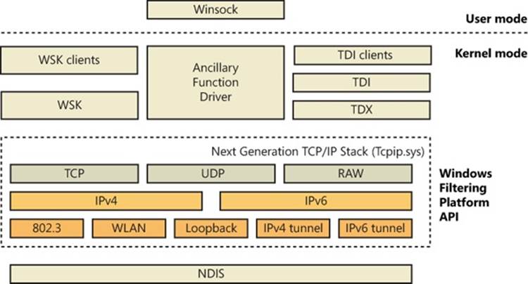
Figure 7-35. Windows Next Generation TCP/IP Stack
EXPERIMENT: LOOKING AT TCP/IP’S DEVICE OBJECTS
Using the kernel debugger to look at a live system, you can examine TCP/IP’s device objects. After performing the !drvobj command to see the addresses of each of the driver’s device objects, execute !devobj to view the name and other details about the device object.
kd> !drvobj tdx
Driver object (861d9478) is for:
\Driver\tdx
Driver Extension List: (id , addr)
Device Object list:
861db310 861db440 861d8440 861d03e8
861cd440 861d2318 861d9350
lkd> !devobj 861cd440
Device object (861cd440) is for:
Tcp6 \Driver\tdx DriverObject 861d9478
Current Irp 00000000 RefCount 7 Type 00000012 Flags 00000050
Dacl 8b1bc54c DevExt 861cd4f8 DevObjExt 861cd500
ExtensionFlags (0x00000800)
Unknown flags 0x00000800
Device queue is not busy.
lkd> !devobj 861db440
Device object (861db440) is for:
RawIp \Driver\tdx DriverObject 861d9478
Current Irp 00000000 RefCount 0 Type 00000012 Flags 00000050
Dacl 8b1bc54c DevExt 861db4f8 DevObjExt 861db500
ExtensionFlags (0x00000800)
Unknown flags 0x00000800
Device queue is not busy.
lkd> !devobj 861d8440
Device object (861d8440) is for:
Udp6 \Driver\tdx DriverObject 861d9478
Current Irp 00000000 RefCount 0 Type 00000012 Flags 00000050
Dacl 8b1bc54c DevExt 861d84f8 DevObjExt 861d8500
ExtensionFlags (0x00000800)
Unknown flags 0x00000800
Device queue is not busy.
lkd> !devobj 861d03e8
Device object (861d03e8) is for:
Udp \Driver\tdx DriverObject 861d9478
Current Irp 00000000 RefCount 6 Type 00000012 Flags 00000050
Dacl 8b1bc54c DevExt 861d04a0 DevObjExt 861d04a8
ExtensionFlags (0x00000800)
Unknown flags 0x00000800
Device queue is not busy.
lkd> !devobj 861cd440
Device object (861cd440) is for:
Tcp6 \Driver\tdx DriverObject 861d9478
Current Irp 00000000 RefCount 7 Type 00000012 Flags 00000050
Dacl 8b1bc54c DevExt 861cd4f8 DevObjExt 861cd500
ExtensionFlags (0x00000800)
Unknown flags 0x00000800
Device queue is not busy.
lkd> !devobj 861d2318
Device object (861d2318) is for:
Tcp \Driver\tdx DriverObject 861d9478
Current Irp 00000000 RefCount 167 Type 00000012 Flags 00000050
Dacl 8b1bc54c DevExt 861d23d0 DevObjExt 861d23d8
ExtensionFlags (0x00000800)
Unknown flags 0x00000800
Device queue is not busy.
lkd> !devobj 861d9350
Device object (861d9350) is for:
Tdx \Driver\tdx DriverObject 861d9478
Current Irp 00000000 RefCount 0 Type 00000021 Flags 00000050
Dacl 8b0649a8 DevExt 00000000 DevObjExt 861d9408
ExtensionFlags (0x00000800)
Unknown flags 0x00000800
Device queue is not busy.
Windows Filtering Platform
Windows includes a rich and extensible platform for monitoring, intercepting, and processing network traffic at all levels in the network stack. Other Windows networking services extend basic networking features of the TCP/IP protocol driver by relying on Windows Filtering Platform (WFP). These include Network Address Translation (NAT), IP filtering, IP inspection, and Internet Protocol Security (IPsec). Figure 7-36 shows how the different components of the WFP are integrated with the TCP/IP stack. These include
§ Filter engine. The filter engine is implemented in both user mode and kernel mode and performs all the filtering operations on the network. Each filter engine component consists of filtering layers, one for each component of the network stack. The user-mode engine, responsible for RPC and IPsec keying policy, among other things, contains approximately 10 filters, while the kernel-mode engine, which performs the network and transport layer filtering of the TCP/IP stack, contains around 50.
§ Shims. Shims are the kernel-mode components that reside between the network stack and the filter engine. They are responsible for making the decision to allow or block network traffic based on their filtering behavior, which is defined by the filter engine. A shim operates in three steps: it parses the incoming data to match incoming values with entries in the filter engine, calls the filter engine to return an action based on the incoming values, and then interprets the action (drop the packet, for example).
§ Base filtering engine (BFE). The BFE is a user-mode service (%SystemRoot%\System32\Bfe.dll) that manages all WFP operations. It is responsible for adding and removing filters from the WFP stack, managing the filter configuration, and enforcing security on the filter database.
§ Callout drivers. Callout drivers are kernel-mode components that add custom filtering functionality outside the basic support provided by the WFP. Callout drivers associate callout functions with one or more kernel-mode filtering layers, and the WFP enables callout functions to perform deep packet inspection and modification. Network Address Translation (described next) and IPsec are implemented as callout drivers, for example.
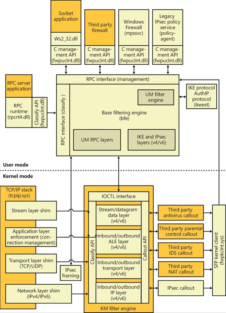
Figure 7-36. Windows Filtering Platform architecture
Network Address Translation
Network Address Translation (NAT) is a routing service that allows multiple private IP addresses to map to a single public IP address. Without NAT, each computer of a LAN must be assigned a public IP address to communicate across the Internet. NAT allows one computer of the LAN to be assigned an IP address and the other computers to use private IP addresses and be connected to the Internet through that computer. NAT translates between private IP addresses and the public IP address as necessary, routing packets between LAN computers and the Internet.
NAT components on Windows consist of a NAT device driver, %SystemRoot%\System32\Drivers\ipnat.sys, that interfaces with the WFP stack as a callout driver, as well as packet editors that can perform additional packet processing beyond address and port translation.
IP Filtering
Windows includes a very basic IP filtering capability with which a user can choose to allow only certain ports or IP protocols into or out of the network. Although this capability can serve to protect a computer from unauthorized network accesses, its drawback is that it is static and does not automatically create new filters for traffic initiated by applications running on the computer.
Windows also includes a host firewall capability, called Windows Firewall, that goes beyond the basic filtering just described. Windows Firewall uses WFP to provide a stateful firewall, which is one that keeps track of traffic flow so that it distinguishes between TCP/IP traffic that originates on the local LAN and unsolicited traffic that originates on the Internet. When Windows Firewall is enabled on an interface, one of three profiles can be applied—public, private, and domain. By default, when the public profile is chosen (or until a profile is selected), all unsolicited incoming traffic received by the computer is discarded. A user or application can define exceptions so that services running on the computer, such as file and printer sharing or a website, can be accessed from other computers.
The Windows Firewall service, which executes in a Svchost process, uses the BFE to pass exception rules defined in the configuration user interface to the IPNat driver. The WFP filter engine executes the callback functions of each registered callout driver as it processes both inbound and outbound IP packets. A callback function can provide NAT functionality by modifying source and destination addresses in a packet, or as a firewall by returning a status code to TCP/IP that requests that TCP/IP drop the packet and cease processing for it. In kernel mode, Windows Firewall uses the Microsoft Protection Service driver (%SystemRoot%\System32\Drivers\Mpsdrv.sys) that provides support for PPTP and FTP filtering, because those protocols provide their own independent control and data channels. The driver must analyze the control channel to figure out which data channel to manipulate. The driver is also used for displaying notification windows when an application starts listening on a socket.
Internet Protocol Security
Internet Protocol Security (IPsec), which is integrated with the Windows TCP/IP stack, helps protect unicast (IPsec itself supports multicast, but the Windows implementation does not) IP data against attacks such as eavesdropping, sniffer attacks, data modification, IP address spoofing, and man-in-the-middle attacks (as long as the identity of the remote machine can be verified, such as a VPN). You can use IPsec to provide defense-in-depth against network-based attacks from untrusted computers; certain attacks that can result in the denial-of-service of applications, services, or the network; data corruption, data theft, and user-credential theft; and the administrative control over servers, other computers, and the network. IPsec helps defend against network-based attacks through cryptography-based security services, security protocols, and dynamic key management.
IPsec provides the following properties for unicast IP packets sent between trusted hosts:
§ Data origin authentication, which verifies the origin of an IP packet and ensures that unauthenticated parties cannot access data.
§ Data integrity, which protects an IP packet from being modified in transit without being detected.
§ Data confidentiality, which encrypts the payload of IP packets before transmission. Data confidentiality ensures that only the IPsec peer with which a computer is communicating can read and interpret the contents of the packets. This property is optional.
§ Anti-replay (or replay protection), which ensures that each IP packet is unique and can’t be reused. This property prevents an attacker from intercepting IP packets and inserting modified packets into a data stream between a source computer and a destination computer. When anti-replay is used, attackers cannot reply to captured messages to establish a session or gain unauthorized access to data.
You can use IPsec to help defend against network-based attacks by configuring host-based IPsec packet filtering and enforcing trusted communications. When you use IPsec for host-based IPsec packet filtering, IPsec can permit or block specific types of unicast IP traffic based on source and destination address combinations and specific protocols and specific ports.
In an Active Directory environment, Group Policy can be used to configure domains, sites, and organizational units (OUs), and IPsec policies (called connection security rules) can then be assigned as required to Group Policy objects (GPOs) through Windows Firewall with Advanced Security configuration settings. Alternatively, you can configure and assign local IPsec policies. Active Directory–based connection security rules are stored in Active Directory, and a copy of the current policy is maintained in a cache in the local registry. Local connection security rules are stored in the local system registry.
To establish trusted communications, IPsec uses mutual authentication, and it supports the following authentication methods through AuthIP, Microsoft’s extension to Internet Key Exchange (IKE):
§ Interactive user Kerberos 5 credentials or interactive user NTLMv2 credentials
§ User x.509 certificates
§ Computer SSL certificates
§ NAP health certificates
§ Anonymous authentication (optional authentication)
§ Preshared key
If AuthIP is not available, plain IKE is also supported by IPsec. The Windows implementation of IPsec is based on IPsec Requests for Comments (RFCs). The Windows IPsec architecture includes Windows Firewall with Advanced Security, the legacy IPsec Policy Agent, the IKE and Authenticated Internet Protocol (AuthIP) protocols, and an IPsec WFP callout driver, which are described in the following list:
§ Windows Firewall with Advanced Security. In addition to the filtering functionality described earlier, the Windows Firewall service is also responsible for providing the security and policy configuration settings for IPsec, which can be configured through Group Policy either locally or on an Active Directory domain.
§ Legacy IPsec Policy Agent. The legacy IPsec Policy Agent runs as a service. In the Services snap-in in the Microsoft Management Console (MMC), the IPsec Policy Agent appears in the list of computer services under the name IPsec Policy Agent. The IPsec Policy Agent obtains the legacy IPsec policy from an Active Directory domain or the local registry and then passes IP address filters to the IPsec driver and authentication and security settings to IKE. These policies are honored to enable compatibility with older versions of Windows, which implement IPsec management through Active Directory.
§ IKE and AuthIP. IKE is a protocol that supports the authentication and key negotiation services required by IPsec. For outgoing traffic, IKE waits for requests to negotiate security associations (SAs) from the IPsec driver, negotiates the SAs, and then sends the SA settings back to the IPsec driver. For incoming traffic, IKE receives a negotiation request directly from the remote peer, and all other traffic from the peer is dropped until the SAs have been successfully negotiated. SAs are a combination of mutually agreeable IPsec policy settings and keys that defines the security services, mechanisms, and keys that are used to help secure communications between IPsec peers. Each SA is a one-way or simplex connection that secures the traffic it carries. IKE negotiates main mode SAs and quick mode SAs when requested by the IPsec driver. The IKE main mode (or ISAKMP) SA protects the IKE negotiation. The quick mode (or IPsec) SAs protect application traffic. AuthIP is a proprietary extension to IKE supported by Windows Vista and later, while Windows 7 and Windows Server 2008 R2 also add support for IKEv2, an equivalent standardized extension. It adds a secondary authentication mechanism to increase security and simplify maintenance and configuration of IPsec.
§ IPsec WFP callout driver. The IPsec WFP callout driver is a device driver (%SystemRoot%\System32\Drivers\Fwpkclnt.sys) that is bound to WFP and processes packets that pass through the TCP/IP driver. The IPsec driver monitors and secures outbound unicast IP traffic, and it monitors, decrypts, and validates inbound unicast IP packets. WFP receives filters from the IPsec Policy Agent and invokes the callout, which then permits, blocks, or secures packets as required. To secure traffic, the IPsecI driver uses active SA settings, or it requests that new SAs be created.
You can use the Windows Firewall with Advanced Security (%SystemRoot%\System32\Wf.msc) snap-in that is available in MMC to create and manage connection security rules by using the New Connection Security Rule Wizard, shown in Figure 7-37. This snap-in can be used to create, modify, and store local connection security rules or Active Directory–based connection security rules, and to modify connection security rules on remote computers. Alternatively, you can use the Netsh utility with the netsh advfirewall consec command to manage connection security rules. After IPsec-secured communication is established, you can monitor IPsec information for local computers and for remote computers by using the Windows Firewall with Advanced Security snap-in or the Netsh utility with the netsh advfirewall monitor command.
Figure 7-37. New Connection Security Rule Wizard
NDIS Drivers
When a protocol driver wants to read or write messages formatted in its protocol’s format from or to the network, the driver must do so using a network adapter. Expecting protocol drivers to understand the nuances of every network adapter on the market (proprietary network adapters number in the thousands) is not reasonable, so network adapter vendors provide device drivers that can take network messages and transmit them via the vendors’ proprietary hardware. In 1989, Microsoft and 3Com jointly developed the Network Driver Interface Specification (NDIS), which lets protocol drivers communicate with network adapter drivers in a device-independent manner. Network adapter drivers that conform to NDIS are called NDIS drivers or NDIS miniport drivers. The version of NDIS that ships with Windows 7 and Windows Server 2008 R2 is NDIS 6.20.
The NDIS library (%SystemRoot%\System32\Drivers\Ndis.sys) implements the boundary that exists between network transports, such as the TCP/IP driver, and adapter drivers. The NDIS library is a helper library that NDIS driver clients use to format commands they send to NDIS drivers. NDIS drivers interface with the library to receive requests and send back responses. Figure 7-38 shows the relationship between various NDIS-related components.
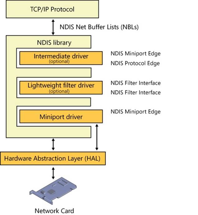
Figure 7-38. NDIS components
Instead of merely providing the NDIS boundary helper routines, the NDIS library provides NDIS drivers with an entire execution environment. NDIS drivers do not follow the standard Windows device driver I/O model, and they cannot function without the encapsulation the NDIS library gives them. This insulation layer wraps NDIS drivers so thoroughly that NDIS drivers don’t accept and process IRPs. Rather, protocol drivers such as TCP/IP call a function in the NDIS library, NdisAllocateNetBufferList, and pass the packets to an NDIS miniport by calling an NDIS library function (NdisSendNetBufferLists). Additionally, to make development simpler, all components of the Windows Next Generation TCP/IP stack make use of the NET_BUFFER_LIST structure, including TCP/IP and WSK, which streamlines communications with NDIS.
NDIS includes the following features:
§ NDIS drivers can report whether or not their network medium is active, which allows Windows to display a network connected/disconnected icon on the taskbar. This feature also allows protocols and other applications to be aware of this state and react accordingly. The TCP/IP transport, for example, uses this information to determine when it should reevaluate addressing information it receives from DHCP.
§ NDIS drivers can be paused and resumed, which enables run-time reconfiguration, such as adding or removing an NDIS Lightweight Filter driver. A lightweight filter replaces most instances of NDIS intermediate drivers used prior to NDIS version 6. (Intermediate drivers are still supported in NDIS 6, but their complexity makes them suitable for only a small class of problems.) Lightweight filter drivers are covered in more detail in the upcoming sections.
§ TCP/IP offloading, including task and chimney offloading. Task offloading allows a network interface card to implement some or all of the TCP/IP protocol stack, providing a substantial increase in network performance. NDIS includes support for IPsec Task Offload Version 2, which includes support for additional cryptography suites used in IPsec, such as AES, as well as IPv6 support. Chimney offloading provides a direct connection (the so-called chimney) between network applications and the network card hardware, enabling greater offloading and connection state management to be implemented by the network card. These offloading operations can improve system performance by relieving the CPU from the tasks.
§ Receive-side scaling enables systems with multiple processors to perform packet receive operations based on the most efficient use of available target processors. NDIS supports the receive-side scaling (RSS) interface at the hardware level and targets interrupts and DPCs to the appropriate processors.
§ Wake-on-LAN allows a wake-on-LAN-capable network adapter to bring the system out of a suspended power state. Events that can trigger the network adapter to signal the system include media connections (such as plugging a network cable into the adapter), the receipt of protocol-specific patterns registered by a protocol (the TCP/IP transport asks to be woken for Address Resolution Protocol [ARP] requests), and, for Ethernet adapters, the receipt of a magic packet (a network packet that contains 16 contiguous copies of the adapter’s Ethernet address).
§ Header-data split allows compatible network cards to improve network performance by splitting the data and header part of an Ethernet frame into different buffers and subsequently combining the buffers into smaller regions of memory than if the buffers were combined. This allows more efficient memory usage as well as better caching because multiple headers can fit in a single page.
§ Connection-oriented NDIS (CoNDIS) allows NDIS drivers to manage connection-oriented media (typically, a WAN), such as ISDN or PPP devices. (CoNDIS is described in more detail shortly.)
The interfaces that the NDIS library provides for NDIS drivers to interface with network adapter hardware are available via functions that translate directly to corresponding functions in the HAL.
EXPERIMENT: LISTING THE LOADED NDIS MINIPORTS
The Ndiskd kernel debugger extension library includes the !miniports and !miniport commands, which let you list the loaded miniports using a kernel debugger and, given the address of a miniport block (a data structure Windows uses to track miniports), see detailed information about the miniport driver. The following example shows the !miniports and !miniport commands being used to list all the miniports and then specifics about the miniport responsible for interfacing the system to a PCI Ethernet adapter. (Note that WAN miniport drivers work with dial-up connections.)
lkd> .load ndiskd
Loaded ndiskd extension DLL
lkd> !miniports
NDIS Driver verifier level: 0
NDIS Failed allocations : 0
Miniport Driver Block: 86880d78, Version 0.0
Miniport: 868cf0e8, NetLuidIndex: 1, IfIndex: 9, RAS Async Adapter
Miniport Driver Block: 84c3be60, Version 4.0
Miniport: 84c3c0e8, NetLuidIndex: 3, IfIndex: 15, VMware Virtual Ethernet Adapter
Miniport Driver Block: 84c29240, Version 0.0
Miniport: 84c2b438, NetLuidIndex: 0, IfIndex: 2, WAN Miniport (SSTP)
...
lkd> !miniport 84bcc0e8
Miniport 84bcc0e8 : Broadcom NetXtreme 57xx Gigabit Controller, v6.0
AdapterContext : 85f6b000
Flags : 0c452218
BUS_MASTER, 64BIT_DMA, IGNORE_TOKEN_RING_ERRORS
DESERIALIZED, RESOURCES_AVAILABLE, SUPPORTS_MEDIA_SENSE
DOES_NOT_DO_LOOPBACK, SG_DMA,
NOT_MEDIA_CONNECTED,
PnPFlags : 00610021
PM_SUPPORTED, DEVICE_POWER_ENABLED, RECEIVED_START
HARDWARE_DEVICE, NDIS_WDM_DRIVER,
MiniportState : STATE_RUNNING
IfIndex : 10
Ndis5MiniportInNdis6Mode : 0
InternalResetCount : 0000
MiniportResetCount : 0000
References : 5
UserModeOpenReferences: 0
PnPDeviceState : PNP_DEVICE_STARTED
CurrentDevicePowerState : PowerDeviceD0
Bus PM capabilities
DeviceD1: 0
DeviceD2: 0
WakeFromD0: 0
WakeFromD1: 0
WakeFromD2: 0
WakeFromD3: 1
SystemState DeviceState
PowerSystemUnspecified PowerDeviceUnspecified
S0 D0
S1 PowerDeviceUnspecified
S2 PowerDeviceUnspecified
S3 D3
S4 D3
S5 D3
SystemWake: S5
DeviceWake: D3
WakeupMethods Enabled 2:
WAKE_UP_PATTERN_MATCH
WakeUpCapabilities:
MinMagicPacketWakeUp: 4
MinPatternWakeUp: 4
MinLinkChangeWakeUp: 0
Current PnP and PM Settings: : 00000030
DISABLE_WAKE_UP, DISABLE_WAKE_ON_RECONNECT,
Translated Allocated Resources:
Memory: ecef0000, Length: 10000
Interrupt Level: 9, Vector: a8
MediaType : 802.3
DeviceObject : 84bcc030, PhysDO : 848fd6b0 Next DO: 848fc7b0
MapRegisters : 00000000
FirstPendingPkt: 00000000
DriverVerifyFlags : 00000000
Miniport Interrupt : 85f72000
Miniport version 6.0
Miniport Filter List:
Miniport Open Block Queue:
8669bad0: Protocol 86699530 = NDISUIO, ProtocolBindingContext 8669be88, v6.0
86690008: Protocol 86691008 = VMNETBRIDGE, ProtocolBindingContext 866919b8, v5.0
84f81c50: Protocol 849fb918 = TCPIP6, ProtocolBindingContext 84f7b930, v6.1
84f7b230: Protocol 849f43c8 = TCPIP, ProtocolBindingContext 84f7b5e8, v6.1
The Flags field for the miniport that was examined indicates that the miniport supports 64-bit direct memory access operation (64BIT_DMA), that the media is currently not active (NOT_MEDIA_CONNECTED), and that it can dynamically detect whether the media is connected or disconnected (SUPPORTS_MEDIA_SENSE). Also listed are the adapter’s system-to-device power-state mappings and the bus resources that the Plug and Play manager assigned to the adapter. (See the section “The Power Manager” in Chapter 8 in Part 2 for more information on power-state mappings.)
Variations on the NDIS Miniport
The NDIS model also supports hybrid network transport NDIS drivers, called NDIS intermediate drivers. These drivers lie between transport drivers and NDIS miniport drivers. To an NDIS miniport driver, an NDIS intermediate driver looks like a transport driver; to a transport driver, an NDIS intermediate driver looks like an NDIS miniport driver. NDIS intermediate drivers can see all network traffic taking place on a system because the drivers lie between protocol drivers and network drivers. Software that provides fault-tolerant and load-balancing options for network adapters, such as Microsoft’s Network Load Balancing Provider, are based on NDIS intermediate drivers. Finally, the NDIS model also implements lightweight filter drivers (LWF), which are similar to intermediate drivers but specifically designed for filtering network traffic. LWFs support dynamic insertion and removal while the protocol stack is running. Filter drivers have the ability to filter all communications to and from the underlying miniport adapter. They also have the ability to select specify types of filtering (packet data or control messages) and to be bypassed for those that they are not interested in.
Connection-Oriented NDIS
Support for connection-oriented network hardware (for example, PPP) is native in Windows, which makes connection management and establishment standard in the Windows network architecture. Connection-oriented NDIS drivers use many of the same APIs that standard NDIS drivers use; however, connection-oriented NDIS drivers send packets through established network connections rather than placing them on the network medium.
In addition to miniport support for connection-oriented media, NDIS includes definitions for drivers that work to support a connection-oriented miniport driver:
§ Call managers are NDIS drivers that provide call setup and teardown services for connection-oriented clients (described shortly). A call manager uses a connection-oriented miniport to exchange signaling messages with network switches or another connection-oriented network medium. A call manager supports one or more signaling protocols. A call manager is implemented as a network protocol driver.
§ An integrated miniport call manager (MCM) is a connection-oriented miniport driver that also provides call manager services to connection-oriented clients. An MCM is essentially an NDIS miniport driver with a built-in call manager.
§ A connection-oriented client uses the call setup and teardown services of a call manager or MCM and the send and receive services of a connection-oriented NDIS miniport driver. A connection-oriented client can provide its own protocol services to higher levels in the network stack, or it can implement an emulation layer that interfaces connectionless legacy protocols and connection-oriented media.
Figure 7-39 shows the relationships between these components.
Figure 7-39. Connection-oriented NDIS drivers
EXPERIMENT: USING NETWORK MONITOR TO CAPTURE NETWORK PACKETS
Microsoft provides a tool named Network Monitor that lets you capture packets that flow through one or more NDIS miniport drivers on your system by installing an NDIS lightweight filter driver (Netmon). You can obtain the latest version of Network Monitor by going to http://www.microsoft.com/download/en/details.aspx?id=4865. Don’t forget to download the NetMon protocol parsers from http://nmparsers.codeplex.com/; otherwise, you won’t be able to decode the Microsoft protocols. When you first start Network Monitor, you’ll see a window similar to the one shown in Figure 7-40.
FIGURE 7-40. NETWORK MONITOR
In the Select Networks pane, Network Monitor lets you select which network connection you want to monitor. After selecting one or more, start the capture environment by clicking the New Capture button on the toolbar. You can now initiate monitoring by clicking the Start button on the toolbar. Perform operations that generate network activity on the connection you’re monitoring (such as browsing to a website), and after you see that Network Monitor has captured packets, stop monitoring by clicking the Stop button. In the Frame Summary pane, you will see all the raw network traffic during the capture period. The Network Conversations pane displays network traffic isolated by process, whenever possible. By clicking on the Iexplore.exe process in this example, Network Monitor shows only the relevant frames in the Frame Summary view, as shown in Figure 7-41.
FIGURE 7-41. CAPTURING PACKETS WITH NETWORK MONITOR
The window shows the HTTP packets that Network Monitor captured as the Microsoft website was accessed through Internet Explorer. If you click on a frame, Network Monitor displays a view of the packet that breaks it apart to show various layered application and protocol headers in the Frame Details pane, as shown in the previous screen shot.
Network Monitor also includes a number of other features, such as capture triggers and filters, that make it a powerful tool for troubleshooting network problems. You can also add parsers for other protocols, as well as view and modify their source code. Network Monitor parsers are hosted on CodePlex (http://nmparsers.codeplex.com), the Microsoft open source project site.
Remote NDIS
Prior to the development of Remote NDIS, a vendor that developed a USB network device had to provide a driver that interfaced with NDIS as a miniport driver as well as interfacing with a USB WDM bus driver, as shown in Figure 7-42.
Figure 7-42. NDIS miniport driver for a USB network device
Remote NDIS is a specification for network devices on USB. The specification eliminates the need for a hardware vendor to write an NDIS miniport driver by defining messages and the mechanism by which the messages are transmitted over USB. Remote NDIS messages mirror the NDIS interface and include messages for initializing and resetting a device, transmitting and receiving packets, setting and querying device parameters, and indicating media link status.
The Remote NDIS architecture, in Figure 7-43, relies on a Microsoft-supplied NDIS miniport driver, %SystemRoot%\System32\Drivers\Rndismp.sys, that translates NDIS commands and forwards them to a USB device. The architecture allows for a single NDIS miniport driver to be used for all Remote NDIS devices on USB.
Figure 7-43. Remote NDIS architecture for USB network devices
Currently, USB is the only bus supported by RNDIS on Windows.
QoS
If no special measures are taken, IP network traffic is delivered on a first-come, first-served basis. Applications have no control over the priority of their messages, and they can experience bursty network behavior, where they occasionally obtain high throughput and low latencies but otherwise receive poor network performance. While this level of service is acceptable in most situations (such as transferring files or browsing the Web), an increasing number of network applications demand more consistent service levels, or Quality of Service (QoS) guarantees. Video conferencing, media streaming, and enterprise resource planning (ERP) are examples of applications that require consistent network performance. QoS allows an application to specify minimum bandwidth and maximum latencies, which can be satisfied only if every networking software and hardware component between a sender and a receiver supports QoS standards such as IEEE 802.1P, an industry standard that specifies the format of QoS packets and how OSI layer 2 devices (switches and network adapters) respond to them.
Windows supports QoS through a policy-based QoS implementation that takes full advantage of the Next Generation TCP/IP network stack, WFP, and NDIS lightweight filter drivers. The implementation allows for managing or prioritizing bandwidth use based on different conditions, such as the application, the source or destination IP address, the protocol being used, and the source or destination ports. Network administrators typically apply QoS settings to a logon session or a computer with Active Directory–based Group Policy, but they can be applied locally as well.
Policy-based QoS provides two methods through which bandwidth can be managed. The first uses a special field in the IP header called the Differentiated Services Code Point (DSCP). Routers that support DSCP read the value and separate packets into specific priority queues. The QoS architecture in Windows can mark outgoing packets with the appropriate DSCP field so that network devices can provide differentiated levels of service. The other bandwidth management method is the ability to simply throttle outgoing traffic based on the conditions outlined earlier, where the QoS components limit bandwidth to a specified rate.
The Windows QoS implementation consists of several components, as shown in Figure 7-44. First, the QoS Client Side Extension (%SystemRoot%\System32\Gptext.dll) notifies the Group Policy client and the QoS Inspection Module that QoS settings have changed. Next, the QoS Inspection Module (Enterprise Quality of Service, eQoS), which is a WFP packet-inspection component implemented in the TCP/IP driver that reacts to policy changes, retrieves the updated policy and works with the transport layer and QoS Packet Scheduler to mark traffic that matches the policy. Finally, the QoS Packet Scheduler, or Pacer (%SystemRoot%\System32\Drivers\Pacer.sys), provides the NDIS lightweight filter functionality, such as throttling and setting the DSCP value, to control packet scheduling based on the QoS policies. Pacer also provides the GQoS (Generic QoS) and TC (Traffic Control) API support for legacy Windows applications that used these mechanisms.
In addition to the systemwide, policy-based QoS support provided by the QoS architecture, Windows enables specific classes of socket-based applications to have individual and specific control of QoS behavior through an API called the Quality Windows Audio/Video Experience, or qWAVE. Network-based multimedia applications, such as Voice over IP (VoIP), can use the qWAVE API to query information on real-time network bandwidth and adapt to changing network conditions, as well as to prioritize packets to efficiently use the available bandwidth. qWAVE also takes advantage of the topology protocols described earlier to dynamically determine if the current network devices will support the required bandwidth for a video stream, for example. It can notify applications of diminishing bandwidth, at which point the multimedia application is expected to reduce the stream quality, for example.
Figure 7-44. Policy-based QoS architecture
qWAVE is implemented in the QoS2 (%SystemRoot%\System32\Qwave.dll) API library and provides four main components:
§ Admission control, which determines, when a new network multimedia stream is started, if the current network can support the sustained bandwidth requested.
§ Caching, which allows the detailed admission control checks to be bypassed if similar usage patterns occurred in the past and the calculation result was already cached.
§ Monitoring and probing, which keep track of available bandwidth and notify applications during low-bandwidth or high-latency situations.
§ Traffic tagging and shaping, which uses the 802.11p and DSCP technologies mentioned earlier to tag packets with the appropriate priority to ensure timely delivery.
Figure 7-45 shows the general overview of the qWAVE architecture:
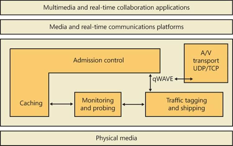
Figure 7-45. qWAVE architecture
Binding
The final piece in the Windows networking architecture puzzle is the way in which the components at the various layers—networking API layer, transport driver layer, NDIS driver layer—locate one another. The name of the process that connects the layers is binding. You’ve witnessed binding taking place if you’ve changed your network configuration by adding or removing a component using the Network Connections folder.
When you install a networking component, you must supply an INF file for the component. (INF files are described in Chapter 8 in Part 2.) This file includes directions that setup API routines must follow to install and configure the component, including binding dependencies or binding relationships. A developer can specify binding dependencies for a proprietary component so that the Service Control Manager (the Service Control Manager is described in Chapter 4) will not only load the component in the correct order but will load the component only if other dependent components are present on the system. Binding relationships, which the bind engine determines with the aid of additional information in a component’s INF file, establish connections between components at the various layers. The connections specify which components a network component on one layer can use on the layer beneath it.
For example, the Workstation service (redirector) automatically binds to the TCP/IP protocol. The order of the binding, which you can examine on the Adapters And Bindings tab in the Advanced Settings dialog box (shown in Figure 7-46), determines the priority of the binding. (See the section Multiple Redirector Support earlier in this chapter for instructions on how to launch the Advanced Settings dialog box.) When the redirector receives a request to access a remote file, it submits the request to both protocol drivers simultaneously. When the response comes, the redirector waits until it has also received responses from any higher-priority protocol drivers. Only then will the redirector return the result to the caller. Thus, it can be advantageous to reorder bindings so that bindings of high priority are also the most performance efficient or applicable to most of the computers in your network. You can also manually remove bindings with the Advanced Settings dialog box.
Figure 7-46. Editing bindings with the Advanced Settings dialog box
The Bind value, in the Linkage subkey of a network component’s registry configuration key, stores binding information for that component. For example, if you examine HKLM\SYSTEM\CurrentControlSet\Services\LanmanWorkstation\Linkage\Bind, you’ll see the binding information for the Workstation service.
Layered Network Services
Windows includes network services that build on the APIs and components we’ve presented in this chapter. Describing the capabilities and detailed internal implementation of all these services is outside the scope of this book, but this section provides a brief overview of remote access, Active Directory, Network Load Balancing, and Distributed File System (DFS), including DFS Replication (DFSR).
Remote Access
Remote access, which is available with Windows Server with the Routing and Remote Access service, allows remote access clients to connect to remote access servers and access network resources such as files, printers, and network services as if the client were physically connected to the remote access server’s network. Windows provides two types of remote access:
§ Dial-up remote access is used by clients that connect to a remote access server via a telephone or other telecommunications infrastructure. The telecommunications medium is used to create a temporary physical or virtual connection between the client and the server.
§ Virtual private network (VPN) remote access lets a VPN client establish a virtual point-to-point connection to the server over an IP network such as the Internet. Windows also supports the Secure Socket Transmission Protocol (SSTP), which is a newer tunneling protocol for VPN connections that has the ability to pass through most firewalls and routers that block PPTP or L2TP/IPsec traffic. It does so by packaging PPP data over the SSL channel of the HTTPS protocol. Because the latter operates on port 443 and is usually part of typical Web browsing behavior, it is much more likely to be available than traditional VPN tunneling protocols.
Remote access differs from remote control solutions because remote access acts as a proxy connection to a Windows network, whereas remote control software executes applications on a server, presenting a user interface to the client.
Active Directory
Active Directory is the Windows implementation of Lightweight Directory Access Protocol (LDAP) directory services (RFC 4510). Fundamentally, Active Directory is a database that stores objects representing resources defined by applications in a Windows network. For example, the structure and membership of a Windows domain, including user accounts and password information, are stored in Active Directory.
Object classes and the attributes that define properties of objects are specified by a schema. The objects in the Active Directory are hierarchically arranged, much like the registry’s logical organization, where container objects can store other objects, including other container objects. (See Chapter 6 for more information on container objects.)
Active Directory supports a number of APIs that clients can use to access objects within an Active Directory database:
§ The LDAP C API is a C language API that uses the LDAP networking protocol. Applications written in C or C++ can use this API directly, and applications written in other languages can access the APIs through translation layers.
§ Active Directory Service Interfaces (ADSI) is a COM interface to Active Directory implemented on top of LDAP that abstracts the details of LDAP programming. ADSI supports multiple languages, including Microsoft Visual Basic, C, and Microsoft Visual C++. ADSI can also be used by Microsoft Windows Script Host (WSH) applications.
§ Messaging API (MAPI) is supported for compatibility with Microsoft Exchange client and Outlook Address Book client applications.
§ Security Account Manager (SAM) APIs are built on top of Active Directory to provide an interface to logon authentication packages such as MSV1_0 (%SystemRoot%\System32\Msv1_0.dll, which is used for legacy NT LAN Manager authentication) and Kerberos (%SystemRoot%\System32\Kdcsvc.dll).
§ Windows NT 4 networking APIs (Net APIs) are used by Windows NT 4 clients to gain access to Active Directory through SAM.
§ NTDS API is used to look up SIDs and GUIDs in an Active Directory implementation (via DsCrackNames mostly) as well as for its main purposes, Active Directory management and replication. Several third parties have written applications that monitor Active Directory from these APIs.
Active Directory is implemented as a database file that, by default, is named %SystemRoot%\Ntds\Ntds.dit and replicated across the domain controllers in a domain. The Active Directory directory service, which is a Windows service that executes in the Local Security Authority Subsystem (LSASS) process, manages the database, using DLLs that implement the on-disk structure of the database as well as provide transaction-based updates to protect the integrity of the database. The Active Directory database store is based on a version of the Extensible Storage Engine (ESE), also known as the JET Blue, database used by Microsoft Exchange Server 2007, Desktop Search, and Windows Mail. The ESE library (%SystemRoot%\System32\Esent.dll) provides routines for accessing the database, which are open for other applications to use as well. Figure 7-47 shows the Active Directory architecture.
Figure 7-47. Active Directory architecture
Network Load Balancing
As stated earlier in the chapter, Network Load Balancing, which is included with server versions of Windows, is based on NDIS lightweight filter technology. Network Load Balancing allows for the creation of a cluster containing up to 32 computers, which are called cluster hosts in Network Load Balancing. The cluster can maintain multiple dedicated IP addresses and a single virtual IP address that is published for access by clients. Client requests go to all the computers in the cluster, but only one cluster host responds to the request. The Network Load Balancing NDIS drivers effectively partition the client space among available cluster hosts in a distributed manner. This way, each host handles its portion of incoming client requests, and every client request always gets handled by one and only one host. The cluster host that determines it should handle a client request allows the request to propagate up to the TCP/IP protocol driver and eventually a server application; the other cluster hosts don’t. If a cluster host fails, the rest of the cluster realizes that the cluster host is no longer a candidate for processing requests and redistributes the incoming client requests to the remaining cluster hosts. No new client requests are sent to the failed cluster host. Another cluster host can be added to the cluster as a replacement, and it will then seamlessly start handling client requests.
Network Load Balancing isn’t a general-purpose clustering solution because the server application that clients communicate with must have certain characteristics: the first is that it must be based on protocols supported by the Windows TCP/IP stack, and the second is that it must be able to handle client requests on any system in a Network Load Balancing cluster. This second requirement typically means that an application that must have access to shared state in order to service client requests must manage the shared state itself—Network Load Balancing doesn’t include services for automatically distributing shared state across cluster hosts. Applications that are ideally suited for Network Load Balancing include a web server that serves static content, Windows Media Server, and Terminal Services. Figure 7-48 shows an example of a Network Load Balancing operation.
Figure 7-48. Network Load Balancing operation
Network Access Protection
One of the most difficult challenges that network administrators face is ensuring that systems that connect to their private networks are up to date and meet the organization’s health policy requirements. A health policy contains the specific requirements that a system must meet, such as the minimum required system hotfixes, or a minimum antivirus signature version. Enforcing these requirements is even more difficult when the systems, such as home computers or laptops, are not under the network administrator’s control. Attackers often create malware that targets out-of-date software, so users who do not keep their systems up to date with the most recent operating system updates or antivirus signatures risk exposing the organization’s private network assets to attacks and viruses.
Network Access Protection (NAP) provides a mechanism that helps network administrators enforce compliance with health requirement policies for all systems that require network access. Systems that do not meet the required health policies are isolated from the network and are placed in quarantine. While in quarantine, the noncompliant system’s network connectivity is severely limited, and it can only see the remediation servers from which it can receive the necessary updates to bring it back into compliance. This ensures that only systems that comply with the health policy requirements are allowed to access the organization’s network. NAP is not designed to protect a network from malicious users; it is designed to help administrators maintain the health of the systems on the network, which in turn helps maintain the network’s overall integrity. NAP is a multivendor system, with clients running on other operating systems, such as Mac OS X and Linux, and several third-party System Health Agents, System Health Validators, and Enforcement Clients.
An exhaustive description of NAP is beyond the scope of this book; however, Figure 7-49 and Figure 7-50 illustrate the various components that implement NAP on client and server systems. A detailed description of NAP can be found at http://technet.microsoft.com/en-us/network/bb545879.aspx.

Figure 7-49. NAP client-side architecture
In brief, the components of NAP on the client include the following:
§ System Health Agent (SHA). Monitors one or more aspects of a client’s health, and provides one or more Statements of Health (SoH) to the local system’s NAP Agent. For example, an antivirus SHA might examine the version numbers of the antivirus engine and virus signature file, and place that information in its SoH. A SHA can be matched to a remediation server so that a noncompliant system will know how to become compliant. For example, a SHA for checking antivirus signatures could be matched to a server that contains the latest antivirus signature file and the antivirus application package. Some SHAs do not need to be matched with a remediation server. For example, a SHA might just report local system settings that a System Health Validator (SHV) running on the NAP server SHV can use to determine whether the system’s firewall is enabled. Windows XP Service Pack 3 and later provide a SHA (%SystemRoot%\System32\Mssha.dll) that monitors the settings of the Windows Action Center (SHA-WAC). This SHA is typically referred to as the Windows SHA, or WSH. To write a SHA, look at the INapSystemHealthAgentBinding2, INapSystemHealthAgentCallback, and INapSystemHealthAgentRequest APIs. The SHA is dependent upon the System Health Validator (SHV), and it is expected that the author of a SHA also provide a SHV.
NOTE
SHA vendors should understand that the evaluation process can happen before the system has an IP address (for example, using 802.1x), so the SHA cannot look for data outside the client system. In addition, the IP address can change at any point in time (for example, if NAP causes the client to move to the quarantine VLAN), so the SHA should not cache sockets or make any assumptions about its IP address.
§ NAP Agent. %SystemRoot%\System32\qagentRT.dll (quarantine agent service runtime). Runs on each client computer, collects the SoH from each SHA, and relays that information to the NAP Server. The NAP Agent communicates with the NAP Server running on the Network Policy Server using the Microsoft Statement of Health protocol [MS-SoH].
§ Enforcement Client (EC). Responsible for communicating with an Enforcement Point when trying to connect to a network, and for enforcing machine compliance with NAP policies. An Enforcement Point is a server or network access device that can be used with NAP to require the evaluation of a NAP client’s health state and provide restricted network access or communication. If the machine’s health is not compliant, the NAP EC indicates the restricted status to the NAP Agent. Windows provides ECs for IPsec (%SystemRoot%\System32\NapIPsec.dll), 802.1X and VPN EAP-authenticated connections (%SystemRoot%\System32\Eapqec.dll), DHCP (%SystemRoot%\System32\Dhcpqec.dll), and a Remote Desktop gateway (%SystemRoot%\System32\Tsgqec.dll). To write an EC, look at the INapEnforcementClientBinding, INapEnforcementClientCallback, and INapEnforcementClientConnection2 APIs.
NOTE
The name “enforcement client” can be somewhat confusing. The name refers to its role as a client of a network enforcement point, so it is more about how a client system accesses a network (although access control is generally part of its function).
The following diagram shows the NAP components on a server. On the server side, the entire mechanism is an add-on to the Network Policy Server (NPS) Server (part of the IAS service). In general, the health requests arrive at the NPS as an addition to RADIUS requests sent to the NPS by the enforcement point. The servers, the NPS then passes the Statement of Health (SoH) to the health validation layer, which passes the SoH to the appropriate SHV.
From the NPS perspective, the requests are coming from RADIUS clients (for example, 802.1x network switch, VPN server, DHCP server, and so on) in RADIUS UDP packets. Or it allows private ALPC calls. (Instead of going through UDP, the ALPC is used by the other Windows Server roles—for example, DHCP server—to simplify the programming model.) The RADIUS specification (RFC 2865) provides for a maximum packet size of 4096, which has a significant impact on the amount of data that a SHA can send.
The client IPsec EC talks to a Health Registration Authority (HRA) server over HTTP. The HRA is an IIS ISAPI filter, which passes the SoH to the NPS (using the ALPC interface) and is responsible for issuing the certificates (when the machine is identified as qualified for a certificate). The HRA server list can be configured using DNS, by adding HRA server records and configuring the client to get the list from DNS. Third parties can implement a RADIUS client to talk to the NPS over UDP.
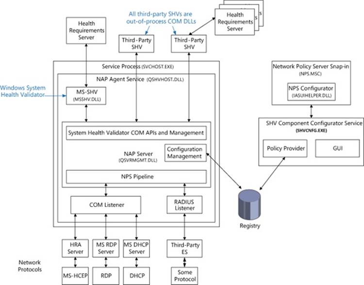
Figure 7-50. NAP server-side architecture
§ System Health Validator (SHV). Evaluates a SoH received from the corresponding SHA on a client and determines whether the client is in compliance with the organization’s health policy by checking with a Health Requirements Server (HRS). For example, an antivirus HRS might specify the minimum antivirus engine version and virus signature file version.
NOTE
The presence of a Health Requirements Server is an implementation detail; an SHV can perform all the necessary work on its own.
The SHV uses this information to determine whether the SoH provided by the client SHA is in compliance with the health policy provided by the HRS. To write a SHV, look at the INapSystemHealthValidator and INapSystemHealthValidationRequest2 APIs. The SHV is dependent upon the System Health Agent (SHA), and it is expected that the author of a SHA also provide a SHV.
Not pictured in the diagram are one or more Remediation Servers, which allow a client to be brought into compliance (for example, a Windows Update server). The SHV is not connected to the Remediation Servers, but it is aware of their existence (configured administratively). It passes information about the servers to the client when the SoH indicates that the client is not compliant with the current policy requirements.
NAP client configuration is typically done in the Group Policy editor with the Enforcement Client snap-in, but it can also be performed using the NAP client configuration MMC snap-in (%SystemRoot%\System32\Napclcfg.msc) or the network shell (%SystemRoot%\System32\Netsh.exe), as shown in Figure 7-51, Figure 7-52, and Figure 7-53.
NOTE
Group Policy always takes precedence over other configurations, followed by the local configuration, and then by DNS auto-discovery.
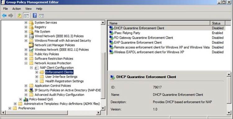
Figure 7-51. NAP Client configuration
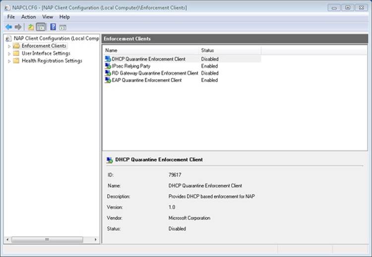
Figure 7-52. NAP Client configuration
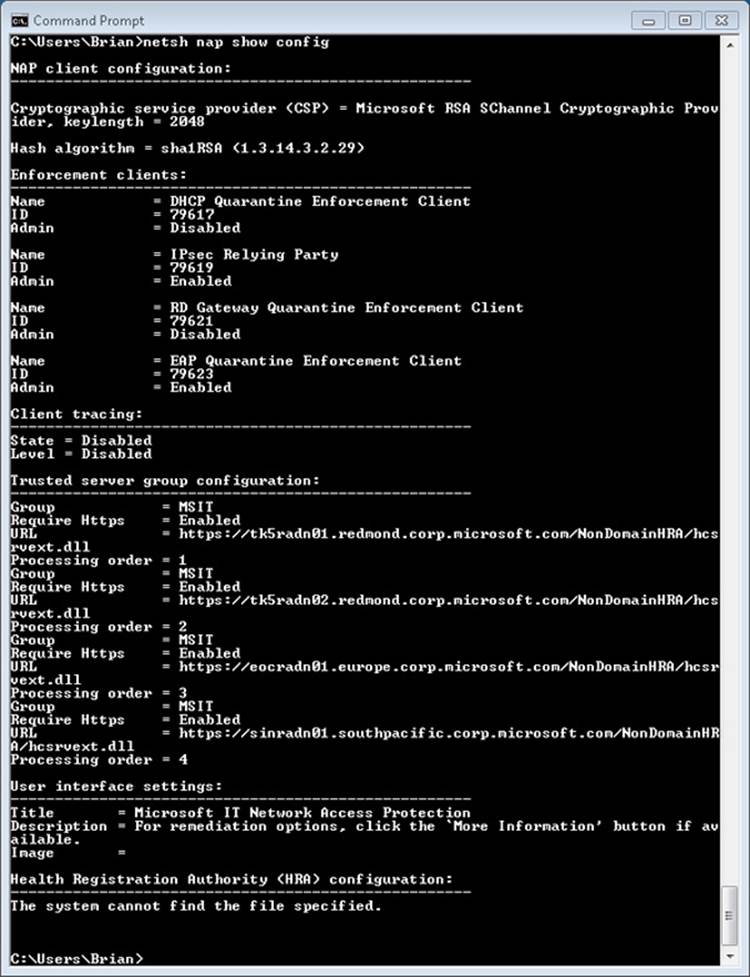
Figure 7-53. Configuring NAP using the network shell
Direct Access
In Windows 7 Ultimate and Enterprise editions, Microsoft added an always-on Virtual Private Network (VPN) capability known as DirectAccess (DA), which allows a remote client on the Internet access to a corporate domain-based network. A DA connection to a corporate network is created when the client system boots, and it lasts for as long as the client is running and connected to the Internet. If network problems cause the connection to be dropped, the connection will be automatically re-established when network connections permit. DA uses IPsec running over IPv6, which can be encapsulated in IPv4 using a variety of mechanisms (described later) if the local system does not have end-to-end IPv6 connectivity to the private network. Remote systems can even use DA when they are behind a firewall, because DA can use HTTPS (TCP port 443) as a transport (IP-HTTPS).
Unlike traditional VPN products, remote systems using DA to access a corporate network are always visible and manageable—just as if the machine was directly plugged into the corporate network. The corporate IT department can manage remote systems by updating Group Policy settings or push software updates at any time the remote systems are attached to the Internet. The IT department can also specify which corporate network resources (applications, servers, subnets, and so on) can be accessed by a user or remote system that is connected using DA.
For enhanced security, Authentication Mechanism Assurance (described in Chapter 6) can be required on DA clients. This requires two-factor authentication (for example, a smart card or other hardware token) to log on or unlock a system.
As shown in Figure 7-54, there are many mechanisms available for connecting a DA client to a corporate network: IPv6, Intra-Site Automatic Tunnel Addressing Protocol (ISATAP), IPv4 encrypted with IPsec, 6to4 tunnel, or Teredo. In all cases, a connection is made between the remote client and a DA server. This server provides Denial of Service (DoS) protection by rate-limiting connection negotiation traffic used to connect to it, and it acts as an IPv6 tunnel gateway between the remote client and the corporate network. The DA server also functions as an IPv6-based IPsec security gateway, similar to a VPN server or VPN client access concentrator, to control access to the corporate network
A client typically has two IPv6 tunnels to the DA server: an infrastructure tunnel and an intranet tunnel. The infrastructure tunnel is for communicating with corporate infrastructure servers, such as a Domain Name System (DNS) server, and domain controllers. The infrastructure tunnel is created automatically when the client boots, and it does not require the user to be logged in. The intranet tunnel is established when a user logs in, and it carries network traffic for the user.
DA also works with NAP. In this case, a Health Registration Authority (HRA) server is placed outside the corporate firewall (often referred to as the DMZ, or DeMilitarized Zone). The client is configured with the name of the HRA (which can be resolved to an IP address using a public DNS server). When the client boots, it contacts the HRA and sends its Statement of Health. If the client is not healthy, it must access remediation servers, which are also in the DMZ. Once the client is healthy, it obtains a health certificate that can then be used with IPsec to connect to the DA server.
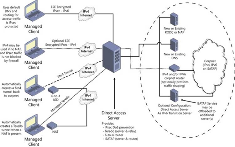
Figure 7-54. Connecting a DA client to a corporate network
Conclusion
The Windows network architecture provides a flexible infrastructure for networking APIs, network protocol drivers, and network adapter drivers. The Windows networking architecture takes advantage of I/O layering to give networking support the extensibility to evolve as computer networking evolves. Similarly, new APIs can interface to existing Windows protocol drivers. Finally, the range of networking APIs implemented on Windows affords network application developers a range of possible implementations, each with different programming models and protocol support.
All materials on the site are licensed Creative Commons Attribution-Sharealike 3.0 Unported CC BY-SA 3.0 & GNU Free Documentation License (GFDL)
If you are the copyright holder of any material contained on our site and intend to remove it, please contact our site administrator for approval.
© 2016-2026 All site design rights belong to S.Y.A.