Microsoft .NET Architecting Applications for the Enterprise, Second Edition (2014)
Part II: Devising the architecture
CHAPTER 5 Discovering the domain architecture
CHAPTER 6 The presentation layer
CHAPTER 7 The mythical business layer
Chapter 5. Discovering the domain architecture
Essentially, all models are wrong, but some are useful.
—George P. O. Box
Software definitely stems from mathematics and is subject to two opposing forces: the force of just doing things and the force of doing things right. We like to think that software is overall a big catch-me-if-you-can game. Visionary developers riding on the wings of enthusiasm quickly build a prototype that just works. The prototype then becomes a true part of the business; sometimes what originally was just a prototype changes and expands the business. Next, more down-to-earth developers join in to analyze, stabilize, consolidate or, in some cases, rewrite the software as it should have been done the first time, in accordance to theoretical principles.
Software, however, cannot be constrained into too-formal and rigid theorems.
Software mirrors real life, and life follows well-known rules defined in the context of some model. Unfortunately, at some given time, T1, we find that our understanding of the model is in some way limited. At some later time, T2, our understanding might deepen and we become aware of extended rules that better explain the overall model.
That’s how things go in the real world out there; but it’s not always how we make things go in real software.
Software architects tend to restrict the solution within the boundaries of a fixed, top-level architecture. We have done it ourselves many times. If we look back, we find it is a common error to start defining some top-level architecture (for example, Client/Server, Layered Architecture, Hexagonal) and then use it everywhere in our business application. That approach might work in the end, but the working solution you reach descends from the wrong approach. It’s a sort of technical debt you are going to end up paying at some point.
Because software is expected to mirror real life, as a software architect you should first understand the segment of the real world you are modeling with software. That segment of the real world is the business domain, and it might contain multiple business contexts, each calling for its own ideal architecture.
The real added value of domain-driven design
Domain-Driven Design, or DDD for short, is a particular approach to software design and development that Eric Evans introduced over a decade ago. The essence and details of DDD are captured in the book Domain-Driven Design, which Evans wrote for Prentice Hall back in 2003. The book subtitle transmits a much clearer message about the purpose of DDD: Tackling Complexity in the Heart of Software.
When it debuted, DDD was perceived as an all-or-nothing approach to application design. You were given a method, some quite innovative guidelines, and the promise that it would work. Using DDD was not actually cheating, and we dare say that it really fulfilled the promise of “making it work”—except that it works only if you do it right. Doing it right is not immensely hard; but it’s also immensely easy to do it wrong. (See Figure 5-1.)
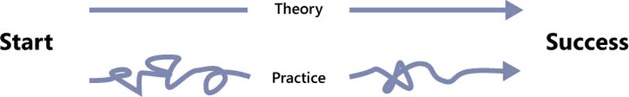
FIGURE 5-1 The DDD road to success is not always as smooth and easy as you expect.
What makes DDD so powerful but also so error prone? We think it’s the context.
DDD is about crunching knowledge about a given business domain and producing a software model that faithfully mirrors it. The business domain is how a company conducts its own business: it’s about organization, processes, practices, people, and language. The business domain lives in a context. Even very similar businesses may live in different contexts.
DDD is easy and powerful to use if you crunch enough knowledge and can model faithfully. DDD is painful and poor if you lack knowledge or fail to turn your knowledge into a model that fits the business domain.
What’s in DDD for me?
However you want to frame it, DDD represents a significant landmark in software development. Not coincidentally, DDD initially was developed in the Java space, where the adoption of advanced design techniques (in the beginning of the last decade) was much faster and more widespread than in the .NET space. For many years, the scope and relevance of DDD was not really perceived in the .NET space.
Do we really need it? That was the question we are often asked and have asked ourselves many times.
DDD is not right for every project because it requires mastery and might have high startup costs. At the same time, nothing in DDD prevents you from using it in a relatively simple system. As we see it, the crucial point to using DDD is understanding where its real value lies and learning techniques to take advantage of it. The two biggest mistakes you can make with DDD are jumping on the DDD bandwagon just because it sounds cool, and stubbornly ignoring DDD because in the end you think your system is only a bit more complex than a plain CRUD.
In summary, we think DDD has two distinct parts. You always need one and can sometimes happily ignore the other.
DDD has an analytical part that sets out an approach to express the top-level architecture of the business domain in terms of bounded contexts. In addition, DDD has a strategic part that relates to defining a supporting architecture for the identified bounded contexts.
The real added value of DDD lies in using the analytical part to identify bounded business contexts. Next, the strategic design might or might not be leveraged to implement any of the bounded contexts.
Conducting analysis using DDD
The analytical part of DDD consists of two correlated elements: the ubiquitous language and bounded contexts.
The ubiquitous language is a vocabulary shared by all parties involved in the project and thoroughly used throughout the projects, ideally in all forms of spoken and written communication. As an architect, you typically populate the vocabulary of verbs and nouns as you acquire knowledge about the domain. This is the most common approach to starting to populate the vocabulary. More generally, you should also carefully look into adverbial phrases you find in requirements, because they might reveal a lot about the domain, such as events, processes, and triggers of processes.
The ubiquitous language is also the template that inspires the names and structure of the classes you end up writing. The ubiquitous language serves to improve and speed up the acknowledgment of requirements and simplify communication between parties so that they avoid misunderstandings, flawed assumptions, and botched translations when moving from one set of jargon to another.
Initially, there’s just one ubiquitous language and a single business domain to understand and model. As you come to understand the requirements and explore the domain further, you might discover some overlap between nouns and verbs and find that they have different meanings in different areas of the domain. This might lead you to think the original domain should be split into multiple subdomains.
Bounded context is the term used with DDD to refer to areas of the domain that are better treated independently because of their own ubiquitous language. Put another way, you recognize a new bounded context when the ubiquitous language changes. Any business domain is made of contexts, and each context is shaped by logical contours. The primary responsibility of a software architect is identifying business contexts in a domain and defining their logical contours.
Context mapping is an expression often used to refer to the analytical part of DDD. Context mapping is a universal technique that can be applied to nearly any software scenario. Context mapping builds a high-level view of the domain from the perspective of a software architect. It shows subdomains and their relationships and helps you make strategic decisions.
Strategic model design
Coupled with context mapping is strategic model design. Once you identify the various bounded contexts, your next problem is determining the best architecture for each. DDD offers a recommended architecture in the form of the layered architecture and Domain Model. The term domain model here is subject to interpretation and deserves a bit of attention.
In the definition of DDD that Evans gives in his seminal book, the term domain model gives a nod to the Domain Model pattern formalized by Martin Fowler: http://martinfowler.com/eaaCatalog/domainModel.html. It consists of special flavor of an object model (also known as the domain model or entity model) and a set of domain service classes. More recently, the internal structure of the domain model is being reconsidered within the community. While seeing the domain model as an ad hoc collection of objects is still the most common perspective, a functional vision of it is gaining ground. Functional programming is, in fact, in many ways preferable to object-orientation for implementing tasks and expressing business concepts.
In the end, we can rephrase the whole thing today by saying that DDD suggests a layered architecture designed around a model of the domain. The model is mostly an object model, but it can be other things too—for example, a collection of functions. The persistence of data also depends on the structure of the model. It might require an O/RM tool if the model is a collection of objects; it might even be based on stored procedures invoked from idiomatic wrapper components if the model is, for example, function-based.
In the next chapters, we’ll explore in depth the most common scenario for the domain model—when it takes the form of a special object model.
Note
According to the original definition given by Evans, DDD is in a way the next natural step for developers versed in object-oriented design (OOD). The first principle of OOD recommends finding “pertinent classes,” as you saw in Chapter 3, “Principles of software design.” DDD recommends that you model the domain carefully—and that you model the domain carefully by discovering pertinent classes.
The phase of strategic model design consists of evaluating the various architectural options and choosing the architecture for each bounded context. Beyond the layered architecture, with a domain model there are usually other options such as a plain CRUD, a CMS (when the bounded context is expected to be a website), or even more sophisticated things, such as event sourcing (which we’ll talk about in upcoming chapters.
Which parameters should drive your choice?
Overall, we think that today there’s only one guiding rule, and it’s based on the (carefully) estimated lifetime of the software you are about to write. Let’s go through a few scenarios.
Fast-food applications
Suppose you are writing a short-term, one-off application such as a survey web application or some analogous set of pages aimed at collecting raw data for your analysts. You know that the expected lifetime is very short and that after the expected data has been collected the app will be bluntly dismissed.
Does it really make sense to invest more than the least amount of time that could possibly make it work? It probably doesn’t.
So you can go with the quickest possible CRUD you can arrange, whether it is by using Web Forms, Silverlight, or plain HTML, depending on the skills and the target audience. If you are about to think something like, “Hey, I’m a senior architect, and no boss would pay my time for such trivial problems,” well, you are probably just experiencing the power of bounded contexts already. Taken out of context, a fast-food application is undoubtedly a very basic—even silly—example. But it might be just one bounded context of a much larger and more complex domain that you, as a senior architect, helped to map.
Front-end websites
The project you’re on requires a web front end. It has a sufficiently complex back end, where a lot of business rules must be taken into account and a bunch of external web services must be coordinated, but at the end of the day the front end is a plain set of read-only pages with zero or limited forms. The most important requirement you have for it is, “It must be shockingly cool and engage people.”
Web Forms can be immediately ruled out because of its limited flexibility due to server controls. ASP.NET MVC is a much better option because it allows full control of HTML and can be effectively styled with CSS. Should you really go with an ASP.NET MVC solution from scratch?
Couldn’t a CMS be a quicker and equally cool solution?
We can probably hear the same objections—it’s a silly example for a book that claims to target software architects. Yes, but a software architect recognizes complexity where she sees it and doesn’t create any unnecessary complexity.
You might know that plugins can extend a CMS, like WordPress, to do almost anything you can think of. It’s not a far-fetched idea to just get a cool WordPress theme and a bunch of plugins, including custom plugins, to do the job.
Again, it’s a matter of opportunity and skills. It’s a matter of context.
Any other types of applications
As Thomas Edison used to say, the value of an idea lies in the using of it. So make-the-code-just-work is a common approach, especially in these hectic days of emerging ideas and startups. The make-the-code-just-work motto is fine if you don’t need to touch the code once it’s done and it works.
No matter what the customer might say and no matter what the current plans are, there’s just one reason that any software avoids further changes: it gets dismissed. If the software is not expected to be dismissed in just a few months, as an architect you better consider a more thoughtful approach than just fast-food code. And Domain Model and the other supporting architectures we’re slated to discuss in the upcoming chapters are the best options available for simplifying code maintenance.
 Note
Note
This is simply a gentle reminder that, not coincidentally, maintainability is both an OOD design goal and a class of requisites according to ISO 9126.
The ubiquitous language
Requirements are always communicated, but we all know that making sense of user requirements is sometimes hard. In addition, the inability to completely comprehend user requirements is probably the primary cause of misunderstandings between business and development teams.
As a way to mitigate the risks of misunderstandings at any time, Eric Evans suggested the use of a common language that he called the ubiquitous language.
Purpose of the ubiquitous language
We write software for a specific business, but we’re software architects in the end and we might not be black-belt experts of the specific business domain. Likewise, domain experts might have some working knowledge of software development but probably not enough to avoid misunderstandings and incorrect assumptions.
Developers and domain experts often just speak different languages, and each group has its own jargon. Furthermore, it is not unlikely that different business people involved—say, from different departments—might use different jargon and give the same term different meanings. The language barrier might not preclude business from taking place, but it certainly makes any progress much slower than expected and acceptable. Translation from one language to another must be arranged; jargon expressions must be adjusted and put into context. This not only takes time, but it also introduces the risk of losing details along the way.
The purpose of the ubiquitous language is to define a common terminology shared by all involved parties—managers, end users, developers, and stakeholders in general—and at all levels—spoken and written communication, documentation, tests, and code. A common language reduces the need for translating concepts from the business to the development context, promotes clarity, and minimizes assumptions.
Once defined, the ubiquitous language becomes the official, all-encompassing language of the project.
Structure of the ubiquitous language
The ubiquitous language is not the raw language of the business, nor is it the language of the development teams. Both business and development language are forms of jargon, and both languages, if taken literally, might lack or skim over essential concepts, as well as generate misunderstandings and communication bottlenecks.
Figure 5-2 shows the canonical diagram used in literature to indicate the relationship between ubiquitous language and native languages spoken by domain experts and development teams.
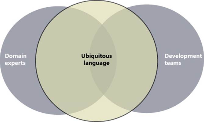
FIGURE 5-2 The canonical diagram that illustrates how the ubiquitous language unifies domain and technical concepts and extends them.
The figure shows that the ubiquitous language is a combination of domain and technical jargon. However, the ubiquitous language is expected to contain, for the most part, words and verbs that reflect the semantics of the business domain rather than technology terms.
It is not limited to the business jargon, however. While technical concepts like caching data, invoking a service, and deleting records of a database should not be part of the language, terms that indicate persistent actions, the response of the system, or notifications sent or received might be necessary to make the resulting language faithfully express the final behavior of the system.
The ubiquitous language exists in the subsoil of the domain. The architect must dig it out at the beginning of the project.
How to define the ubiquitous language
The ubiquitous language is not artificially created in a lab and then submitted for approval to involved parties. Quite the reverse—the language emerges out of interviews and meetings and gets its final shape iteratively along the way. It might take several steps of refinement and adjustment before the language flows as expected and faithfully expresses the reality of the system being built.
The first draft of the language commonly results from acknowledging requirements as architects rewrite and make sense of raw requirements collected during elicitation.
As a technical person, you should expect the language to be rigorous (for example, strictly unambiguous and consistent), fluent, and made of simple elements that can be combined to compose more sophisticated concepts and actions.
As a domain expert, you should hesitate to accept any terms and concepts the language might contain that are unknown in the domain and that are not clearly referring to a process or business concept. Also, as a domain expert, you should ensure that all relevant business terms are defined in the language and, more importantly, are given the right meaning. For example, if the language contains the term account, the term must refer to the meaning that account has in the domain space.
Note
In general, the ubiquitous language contains business terms (nouns and verbs) plus new terms (mostly verbs) that more or less directly map to technical actions, such dealing with databases, cache and security, services and so forth. The number of nonbusiness concepts, however, should be kept to a minimum.
The ubiquitous language is the official language of the project, and the vocabulary of terms is inspired and then validated by domain experts. Everything in the project, from documentation to actual code, is permeated by the language.
How would you physically express and save the vocabulary of the ubiquitous language? In practical terms, it consists of a glossary of terms and expressions saved to a Microsoft Word or Microsoft Excel document or even some UML diagrams. Each term is fully explained in a way that makes it understandable to both domain experts and developers.
It should be the responsibility of the team to keep the glossary up to date throughout the project. The ubiquitous language, in fact, is anything but static. It can change and evolve over time to reflect new insights gained about the domain.
 Important
There are two main scenarios where the analytical part of DDD excels. One is when there’s really a lot of domain logic to deal with that is tricky to digest, distill, and organize. Having a ubiquitous language here is key because it ensures that all terms used are understood and that no other terms are used to express requirements, discuss features, and write code.
Another scenario is when the business logic is not completely clear because the actual business is being built and the software is just part of the initial effort. Startups are an excellent example of this scenario. In this case, the domain logic is being discovered and refined along the way, making the availability of a ubiquitous language a great benefit to understand where one is and where the business can move forward.
Keeping language and model in sync
Naming and coding conventions used in the domain model should reflect naming conventions set in the ubiquitous language. This relationship should not vary during the lifetime of the project.
If the language changes because of a different level of understanding, or a new requirement, then the naming and coding conventions in the domain model should be updated. Also, the opposite is true to a large extent, in the sense that renaming a class or a method is always possible but doing so should require approval if the class or method is pervasive and the change affects a key term of the language. At the same time, it nearly goes without saying that if a given class or method exists only to serve implementation purposes, the constraint doesn’t apply and you can rename it without restrictions.
Let’s briefly look at an example that refers to the code we’ll be examining in more detail in Chapter 8, “Introducing the domain model,” and beyond. The domain is an online store, and the use-case we focus on is the placement of an order.
Each order is reasonably associated with a record in a table and with a column that indicates the current state. The order ID is used to track ordered items from another table. Processing the order requires first a check to see if there are pending or delayed payments from the same customer. Next, the process requires a check on goods in store and, finally, a call to the shipping and payment web services and the creation of a new order record.
Here’s a more domain-driven way of expressing the same use-case. As you can see, the description is more concise and uses fewer technical details. The terms used should also reflect the jargon used within the organization. Here’s an example.
As a registered customer of the I-Buy-Stuff online store, I can redeem a voucher for an order I place so that I don’t actually pay for the ordered items myself.
There are a few business terms here—registered customer, order, order items, and voucher. There are also actions, such as placing an order and redeeming a voucher. All these belong to the ubiquitous language glossary. In particular, the term voucher here is the term used in the business, and once it is added to the ubiquitous language, nobody will ever think of using synonyms (such as coupon, gift card, credit note and so forth).
When coding the use-case, a developer will likely create a class to access the database table of orders, and instances of the order class will be materialized from the database and saved back there. However, these are just technical details that don’t belong in the business context. As such, those details should be buried in the folds of the implementation, limited to technical meetings between developers, and never surface in official communication with business people.
This is the essence of the ubiquitous language.
Bounded contexts
In the beginning, you assume one indivisible business domain and start processing requirements to learn as much as possible about it and build the ubiquitous language. As you proceed, you learn how the organization works, which processes are performed, how data is used and, last but not least, you learn how things are referred to.
Especially in a large organization, the same term often has different meanings when used by different people, or different terms are used to mean the same thing. When this happens, you probably crossed the invisible boundaries of a subdomain. This probably means that the business domain you assumed to be one and indivisible is, in reality, articulated in subdomains.
In DDD, a subdomain in the problem space is mapped to a bounded context in the solution space.
A bounded context is an area of the application that requires its own ubiquitous language and its own architecture. Or, put another way, a bounded context is a boundary within which the ubiquitous language is consistent. A bounded context can have relationships to other bounded contexts.
Important
Subdomains and bounded contexts are concepts that sometimes appear to be similar and can be confusing. However, both concepts can be easily understood by looking at the difference between a domain and domain model, which is probably easier to grasp. The domain represents the problem to solve; the domain model is the model that implements the solution to the problem. Likewise, a subdomain is a segment of the domain, and a bounded context is a segment of the solution.
Discovering contexts
Without flying too high conceptually, consider a simple booking system. The front-end web site is certainly a subdomain. Is it the only one? Most likely, the system needs a back-office panel to put content on the site and perhaps extract statistics. This probably makes for another subdomain.
In the current draft of the top-level architecture, we have two candidate bounded contexts.
There are two additional aspects vital to investigate: the boundaries of each bounded context and their relationships.
Marking boundaries of contexts
Sometimes it’s relatively easy to split a business domain into various subdomains, each representing a bounded context to render with software.
But is it splitting or is it partitioning? There is a huge difference between the two.
In the real world, you don’t often see business domains that can be easily partitioned in child domains with nearly no overlapping functions and concepts. So in our experience, it is more a case of splitting than just partitioning. The problems with splitting a business domain are related to marking the boundaries of each context, identifying areas of overlap, and deciding how to handle those areas.
As mentioned, the first concrete clue that you have a new subdomain is when you find a new term used to express a known concept or when the same term is found to have a second meaning. This indicates some overlapping between subdomains. (See Figure 5-3.)
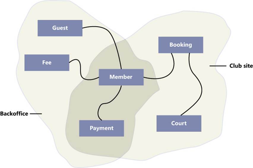
FIGURE 5-3 Two business contexts with some overlapping.
The business domain is made of a subdomain (say, club site) that, among other features, offers the booking of courts. The booking of courts involves members and payments. The back office is a distinct but related subdomain. Both subdomains deal with members and payments, even though each has a different vision of them.
The first decision to be made is whether you need to treat those subdomains separately and, if so, where you draw the boundaries.
Splitting a domain into bounded contexts
Working on a single, all-encompassing model is always dangerous, and the level of complexity grows as the number of entities and their relationships grow. The resulting graph can be crowded; entities and related code can become quite coupled, and it doesn’t take much to serve up the perfect Big Ball of Mud.
Splitting is always a good idea, especially when this leads you to creating software subsystems that reflect the structure of the organization. The back-office system, for example, will be used by different people than the club site.
Let’s say you go for distinct bounded contexts.
How would you deal with overlapping logic? The concept of “club member” exists in both contexts, but in the back-office context the club member has nearly no behavior and is a mere container of personal and financial data. In the club-site context, on the other hand, the member has some specific behaviors because she can book a court or add herself to an existing booking. For doing so, the Member entity will just need an ID, user name, and possibly an email address.
In general, having a single, shared definition of an entity will have the side effect of padding the definition with details that might be unnecessary in some of the other contexts. With reference to Figure 5-3, family members are not necessary to book a court from the club site, but they are relevant to calculating the yearly fee.
The fundamental point to resolve when conceptual overlapping is detected is which of the following options is more appropriate:
• A single bounded context that includes all entities
• A distinct bounded context with a shared kernel of common entities
• A distinct bounded context with distinct definitions of common entities
The options are graphically summarized in Figure 5-4.
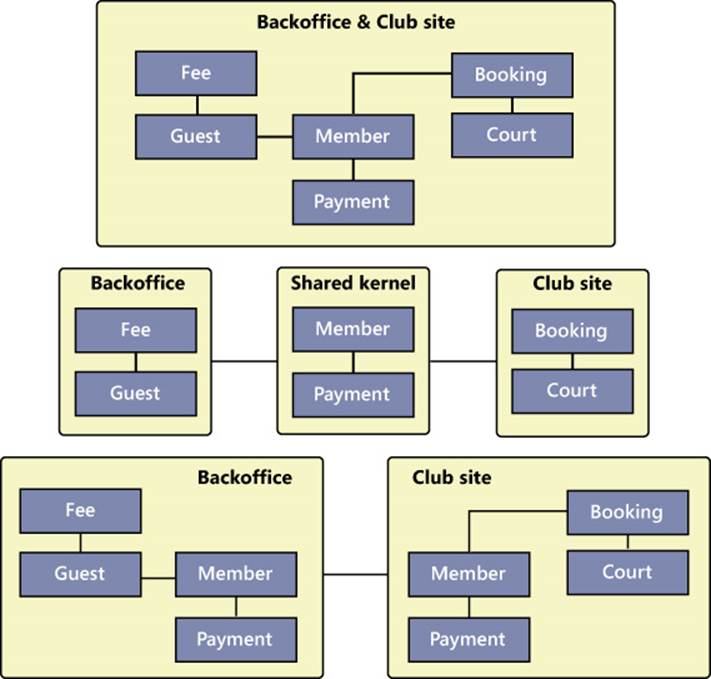
FIGURE 5-4 Resolving the conceptual overlapping of contexts.
There’s also a fourth option. Is the entire model entirely inadequate and in need of refinement so that in the end you can have partitions instead of subsets?
That’s what it means to mark the boundaries of bounded contexts.
By the way, it’s not us dodging the issue by not taking a clear stand on a particular option. It’s that, well, it just depends. It depends on other information about the domain. It depends on time and budget. It depends on skills. It also depends on your personal view of the domain.
That’s what makes it so fun to mark the boundaries of bounded contexts.
Bounded context and the organization
The number of contexts and relationships between bounded contexts often just reflect the physical organization of the enterprise. It is common to have a bounded context for each business department such as human resources, accounting, sales, inventory, and the like.
Different development teams are typically assigned to each bounded context, and different artifacts are generally produced, scheduled, and maintained.
The overlapping of concepts is quite natural in business domains; speaking in general, the best way to handle such overlapping is to use different bounded contexts, as shown in the third option of Figure 5-4.
Just sharing entities between development teams, as a common kernel, might prefigure risky scenarios, where changes of team 1 might break the code of team 2 and compromise the integrity of the model. Shared kernels work great if an effective shared kernel exists—such as different organizations just using the same entities.
Otherwise, it’s the first step toward a true mess.
Context mapping
Bounded contexts are often related to each other. In DDD, a context map is the diagram that provides a comprehensive view of the system being designed. In the diagram, each element represents a bounded context. The diagrams in Figure 5-4 are actually all examples of a context map.
Relational patterns
Connections between elements of a context map depict the relationship existing between bounded contexts. DDD defines a few relational patterns.
Relational patterns identify an upstream context and downstream context. The upstream context (denoted with a u) is the context that influences the downstream and might force it to change. Denoted with d, the downstream context is passive and undergoes changes on the upstream context. Table 5-1 lists DDD relational patterns.
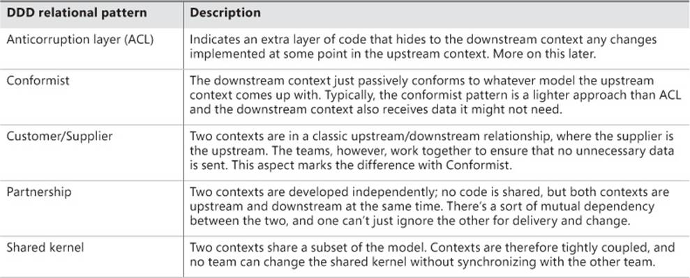
TABLE 5-1. DDD relational patterns
Figure 5-5 is the graphical representation of a context map. Each block represents a bounded context. The Sales block is connected to the upstream External Service block, and an ACL ensures that changes in the service don’t force changes in the Sales context. The upstream and downstream contexts are labeled with the u and d marks.
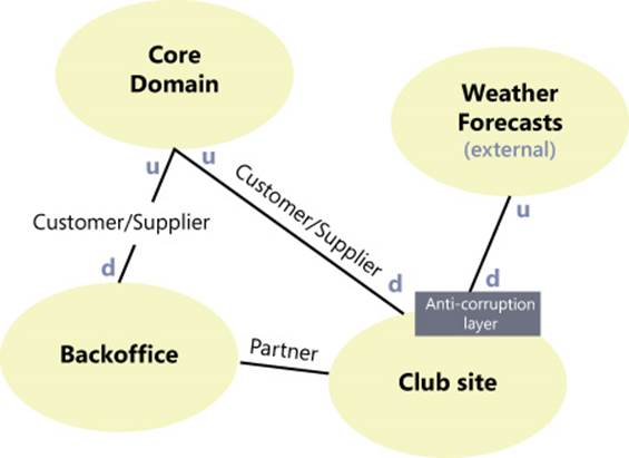
FIGURE 5-5 A sample context map showing some of the DDD relational patterns.
Context mapping is part of the strategic design of the solution. It doesn’t produce code or deployable artifacts, but it can be immensely helpful to grab a better understanding of the system.
Note
Many DDD experts advise that because software ultimately mirrors the structure of business organizations, a context map should ideally reflect the organization of the enterprise. Sometimes, it turns out that the ideal context map for the system to build doesn’t actually reflect the real organization. When this happens—and it does happen—well, things are not going to be easy!
Anticorruption layers
Relationships between bounded contexts pose the problem of how the development of one context influences the other over time. The safest way of dealing with related contexts is by creating an anticorruption layer (ACL).
It’s the safest way because all the changes required to keep the contexts in sync when one undergoes changes are isolated in the anticorruption layer, as shown in Figure 5-6.
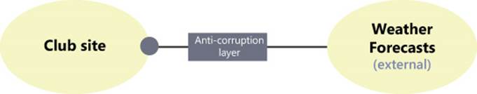
FIGURE 5-6 The anticorruption layer is an interfacing layer that separates two connected contexts.
The interface that the ACL exposes to the downstream context (the club site in this case) is an invariant. The ACL, in fact, absorbs the changes in the upstream context (Weather Forecasts service in this case) and does any conversion work that might be required. Updating the ACL when the upstream context changes usually requires less work and is less obtrusive than updating the club-site context.
The ACL is particularly welcome when one of the bounded contexts encapsulates a chunk of legacy code or just an external service that none of the teams building the system has control over.
Giving each context its own architecture
Each bounded context is a separate area of the overall application. You are forced to use DDD strategic modeling to implement each bounded context, and not only because you identified the bounded context using a DDD methodology. As an architect, you should validate the context map and then focus on each context separately.
For example, the Core Domain area of the application might be implemented using a Domain Model approach. The club-site context can be an ASP.NET MVC application with a layered back end that uses an application layer on top of MVC controllers. The application layer uses services in the Core Domain context for changing the state of the application. Finally, a simpler subsystem like Back Office can be efficiently given a data-driven design and result in a simple two-layer architecture with only presentation and data access. (Concretely, this could be a Web Forms application using DataGrids.)
Another option might be separating the front end of the club site from, say, the booking module. You could use ASP.NET MVC for the booking module and a CMS (for example, WordPress) for the few pages with news, photos, and static content.
Mixing multiple supporting architectures in the realm of a single system is far from wrong.
Common supporting architectures
The process of identifying business contexts already reveals a lot about the nature of the domain and subdomains. To an expert eye that knows about technologies and frameworks, a good candidate solution appears immediately for a given context.
Just as a quick glossary, Table 5-2 lists the most commonly used supporting architectures you might find in the industry.
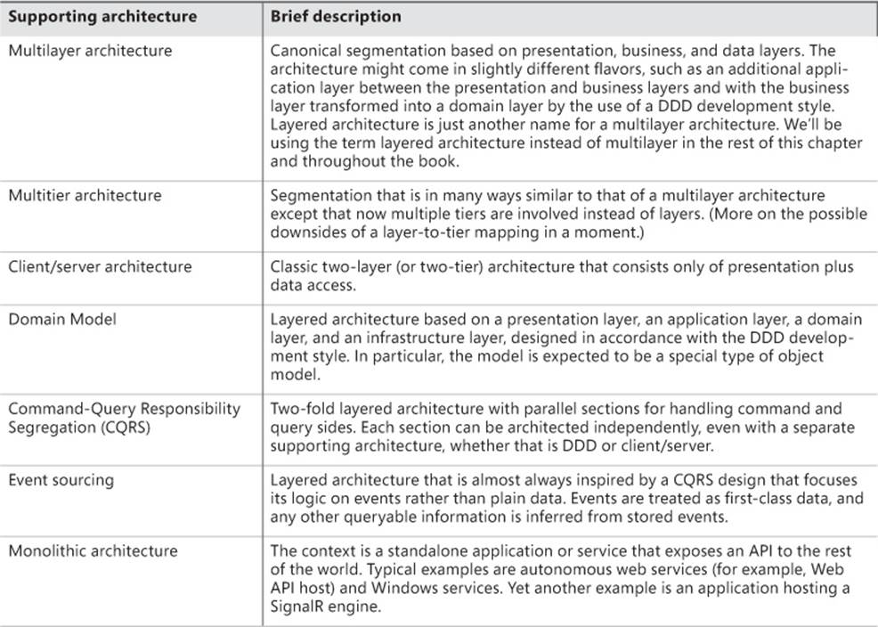
TABLE 5-2. A list of supporting architectures.
As we write this chapter, another architectural style is gaining in popularity: micro-services. At first, micro-services don’t sound like a completely new idea and are not really presented like that. There’s a lot of service-oriented architecture (SOA) in micro-services, such as the fact that services are autonomous and loosely coupled. However, micro-services also explicitly call out for lightweight HTTP mechanisms for communication between processes. For more information on micro-services, you can check out the Martin Fowler’s site athttp://martinfowler.com/articles/microservices.html.
The reason why we mention micro-services here is that, abstractly speaking, the overall idea of micro-services weds well with identifying business contexts, discovering relationships, and giving each its own architecture and autonomous implementation. Micro-services, therefore, can be yet another valid entry in Table 5-2.
Layers and tiers might not be interchangeable
Layers and tiers are not the same. A layer is a logical container for different portions of code; a tier is a physical container for code and refers to its own process space or machine. All layers are actually deployed to a physical tier, but different layers can go to different tiers.
That’s precisely the point we want to raise here.
In Table 5-2, we listed multilayer architecture and multitier architecture. Admittedly, they look the same except that one separates blocks of code logically and the other physically. We suggest, however, that you consider those architectures as different options to be evaluated individually to see if they fit in the solution.
The error that many system integrators made in the past was to deploy a multilayer architecture as a multitier architecture. In doing so, they matched layers to tiers one-to-one. This led to segregating in different tiers the presentation layer of a Web Forms application and the business layer using WCF, Web services or even, in the old days, .NET Remoting. It apparently looked like a better architecture, but it created latency between tiers and had a deep impact on the performance of the system. In addition, system maintenance (for example, deploying updates) is harder and more expensive in a multitier scenario.
Tiers are heavy but can be used to scale the application. However, just having tiers doesn’t automatically ensure your application is faster. Generally speaking, we tend to prefer the deployment of the entire application stack on a single tier, if that’s ever possible.
The layered architecture
In the rest of this chapter, we’ll provide an overview of the layered architecture—the multilayer architecture introduced in Evans’ book about DDD. The layered architecture is probably the most common type of architecture that results from DDD analysis.
Origins of the layered architecture
In the 1990s, most computing scenarios consisted of one insanely powerful server (at least for the time it was) and a few far slower personal computers. Software architecture was essentially client/server: the client focused on data presentation and commands, and the server mostly implemented persistence. Any business logic beyond basic CRUD (Create, Read, Update, Delete) was stuffed in stored procedures to further leverage the capacity of the insanely powerful server machine.
Over the years, we all managed to take larger and larger chunks of the business logic out of stored procedures and place them within new components. This originated the classic (up to) three-segment model, which is shown in Figure 5-7. Note that the figure also shows a direct connection between the presentation and data layers in memory of SQL data binding.
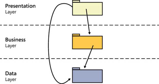
FIGURE 5-7 The classic three-segment architecture.
Note that we’re using the term segment here as a general way to interchangeably refer to both tiers and layers.
From what we have seen, learned, and done ourselves, we’d say that the largest share of systems inspired by the three-segment architecture is actually implemented as a layered system deployed on two physical tiers. For a website, for example, one tier is the ASP.NET application running within the Internet Information Services (IIS) process space and another was the Microsoft SQL Server service providing data. (See Figure 5-8.)
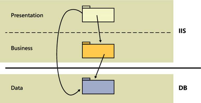
FIGURE 5-8 Common deployment of a multilayer ASP.NET application.
For the most part, the data model of any three-segment architecture is the relational data model of the data store. The growing complexity of applications has led developers to a more conceptual view of that data. As patterns like the Domain Model and approaches like Domain-Driven Design (DDD) were developed and exercised, the internal structure of a layered architecture evolved quite a bit. (See Figure 5-9.)
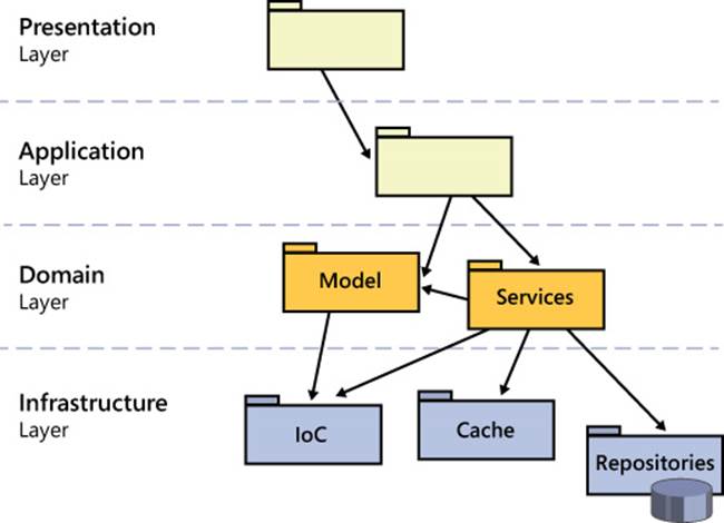
FIGURE 5-9 A more modern version of a layered architecture.
Roughly speaking, the presentation layer is the same in both architectures and the infrastructure layer includes the data layer of Figure 5-7 but is not limited to that. The infrastructure layer, in general, includes anything related to any concrete technologies: data access via O/RM tools, implementation of IoC containers, and the implementation of many other cross-cutting concerns such as security, logging, caching, and more.
The business layer exploded into the application and domain layer. Upon a more thoughtful look, the layered architecture of Figure 5-9 results from a better application of the separation of concerns (SoC) principle. In systems inspired by the schema of Figure 5-7, the actual business logic is sprinkled everywhere, mostly in the business logic but also in the presentation and data layers.
The layered architecture of Figure 5-9 attempts to clear up such gray areas.
Note
Repositories are generally placed in the domain layer as far as their interfaces are concerned. The actual implementation, however, usually belongs to the infrastructure layer.
Presentation layer
The presentation layer is responsible for providing some user interface (UI) to accomplish any tasks. Presentation is a collection of screens; each screen is populated by a set of data and any action that starts from the screen forwards another well-defined set of data.
Generally speaking, we’ll refer to any data that populates the presentation layer as the view model. We’ll refer to any data that goes out of the screen triggering a back-end action as the input model. Although a logical difference exists between the two models, most of the time the view model and input model coincide. (See Figure 5-10.)
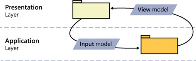
FIGURE 5-10 Describing the data that goes into and out of presentation screens.
Application layer
As we see it, the application layer is an excellent way to separate interfacing layers such as presentation and domain. In doing so, the application layer contributes immensely to the clarity of the entire design. In the past, a typical gray area of many architectures was the placement of the part of the business code that needed to be aware of the presentation.
The application layer is the additional layer that reports to the presentation and orchestrates any further business action. The application layer is where you orchestrate the implementation of use-cases.
Entry point in the system’s back end
Each interactive element of the user interface (for example, buttons) triggers an action in the back end of the system. In some simple scenarios, the action that follows some user’s clicking takes just one step to conclude. More realistically, instead, the user’s clicking triggers something like a workflow.
According to Figure 5-9, the application layer is the entry point in the back end of the system and the point of contact between the presentation and back end. The application layer consists of methods bound in an almost one-to-one fashion to the use-cases of the presentation layer. Methods can be grouped in any way that makes sense to you.
For example, in an ASP.NET MVC application, we expect the application layer classes to go hand in hand with controllers. The HomeController class, therefore, will have injected some HomeControllerService worker class. Here’s a quick sample:
public class HomeController
{
private readonly IHomeControllerService _service;
public HomeController(IHomeControllerService service)
{
_service = service;
}
public ActionResult Index()
{
var model = _service.FillHomePage( /* input model */ );
return View(model);
}
...
}
The mechanism of injection can happen at your leisure. It can happen via Unity or any other Inversion of Control (IoC) container, or it can be done through poor man’s dependency injection, as shown here:
public class HomeController
{
private readonly IHomeControllerService _service;
public HomeController() : this(new HomeControllerService())
{
}
public HomeController(IHomeControllerService service)
{
_service = service;
}
}
In a nutshell, the application layer is responsible for the implementation of the application’s use-cases. All it does is orchestrate tasks and delegate work to other layers down the stack.
We think there can be two flavors of an application layer: inside or outside the business logic. Neither is preferable to the other; it’s all about how you envision the system.
Orchestrating the business logic
In general, the application layer is bound one-to-one to the presentation with the notable exception of unattended systems. The structure of the layer is driven by the actionable controls in the various user interface screens. With reference to Figure 5-5, this flavor of application layer lives in the club-site context and orchestrates workflows involving components in the Core Domain and external services. Key aspects of this application layer are these:
![]() It might or might not be consumable by different front ends because, for example, a mobile front end might have slightly different use-cases than the web front end or ends.
It might or might not be consumable by different front ends because, for example, a mobile front end might have slightly different use-cases than the web front end or ends.
![]() It can be stateful at least as far the progress of a UI task is concerned.
It can be stateful at least as far the progress of a UI task is concerned.
![]() It gets its input from the presentation and sends a view model back as shown in Figure 5-10.
It gets its input from the presentation and sends a view model back as shown in Figure 5-10.
The application layer holds references to the domain layer and infrastructure layer. Finally, the application layer has no knowledge of business rules and doesn’t hold any business-related state information.
As the name suggests, the application layer is just application specific. If our aforementioned booking system must be consumed by a website and a mobile application, we’re going to have two distinct application layers—one on the site and one either within the mobile application or exposed as an HTTP service. Are these layers actually different?
Well, they might be different; and if they’re different, different layers should be implemented. To continue with the booking example, the application layer of the website might redirect to the credit card site to pay and then proceed with the persistence of the booking data. The application layer of the mobile app might use in-app payment features or just use stored payment information and pass them along in some way to the domain layer.
Note
The DDD jargon uses the term application services to refer to services that sit atop the domain layer and orchestrate business use-cases.
Domain layer
The domain layer hosts the entire business logic that is not specific to one or more use-cases. In other words, the domain layer contains all business logic that remains once you have compiled the application layer.
The domain layer consists of a model (known as the domain model) and possibly a family of services. The nature of the model can vary. Most of the time, it is an entity-relationship model, but it can be made of functions too. Let’s stick to what appears to be the most common scenario. So let’s say that at the end of the day an entity model is an object model.
However, in an entity model, constituent classes usually follow certain conventions. We’ll return in detail to domain modeling and DDD conventions for entities in upcoming chapters. For now, it suffices to say that entities in the model are expected to expose both data and behavior. A model with entities devoid of any significant behavior—that is, merely data structures—form an anemic domain model.
The ultimate goal of a domain model is to implement the ubiquitous language and express the actions that business processes require. In this regard, exposing some behavior tends to be more relevant than holding some data.
Along with an entity model, the domain model layer features domain services.
Domain services are pieces of domain logic that, for some reason, don’t fit into any of the existing entities. A domain service is a class, and it groups logically related behaviors that typically operate on multiple domain entities. A domain service often also requires access to the infrastructure layer for read/write operations. In the aforementioned club-site context, a domain service can be the code to book a court:
void BookCourt(Court court, ClubMember member)
Court and ClubMember are domain entities, and the method BookCourt knows how to retrieve and apply due policies.
Infrastructure layer
The infrastructure layer is anything related to using concrete technologies, whether it is data persistence (O/RM frameworks like Entity Framework), specific security API, logging, tracing, IoC containers, caching, and more.
The most prominent component of the infrastructure layer is the persistence layer—which is nothing more than the old-faithful data access layer, only possibly extended to cover a few data sources other than plain relational data stores. The persistence layer knows how to read and/or save data.
The data can reside on a relational server as well as in a NoSQL data store or in both. The data can be accessible through web services (for example, CRM or proprietary services) or live in the file system, cloud, or in-memory databases such as Memcached, ScaleOut, or NCache.
Summary
We dare say that the software industry moved from one extreme to the other. Decades ago, writing software was inspired by the slogan “model first, code later.” This led to considerable efforts to have a big comprehensive design up front. There’s nothing wrong with an upfront design, except that it is like walking on water. It’s definitely possible if requirements, like water, are frozen.
Maybe because of global warming, requirements hardly ever freeze these days. Subsequently, whomever embarks in an upfront design risks sinking after only a few steps.
Mindful of failures of upfront design, architects and developers moved in the opposite direction: code first, model later. This philosophy, although it is awkward, moves things ahead. It just works, in the end. Adopting this approach makes it hard to fix things and evolve, but it delivers working solutions as soon as possible, and if something was wrong, it will be fixed next. Like it or not, this model works. As our friend Greg Young used to write in his old posts, you should never underestimate the value of working software.
What we’re trying to say, however, is that some middle ground exists, and you get there by crunching knowledge and deeply understanding the domain. Understanding the domain leads to discovering an appropriate architecture. However, it doesn’t have to be a single, top-level architecture for the entire application. As you recognize subdomains, you can model each to subapplications, each coded with the most effective architecture. If it still sounds hard to believe, consider that it’s nothing more than the old motto Divide-et-Impera that—historians report—helped Julius Caesar and Napoleon to rule the world.
Finishing with a smile
Developers sometimes enter into God mode and go off on a tangent, thus losing perspective on their code. We try to see models everywhere and to see each model as a special case. This makes software design cumbersome at times, and funny. For more tongue-in-cheek examples of Murphy’s law beyond the following ones, have a look at http://www.murphys-laws.com:
![]() All generalizations are false, including this one.
All generalizations are false, including this one.
![]() The weakest link is the most stable one.
The weakest link is the most stable one.
![]() Never underestimate the value of working software.
Never underestimate the value of working software.