Exam Ref 70-414 Implementing an Advanced Server Infrastructure (2014)
Chapter 2. Plan and implement a highly available enterprise infrastructure
The second set of exam objectives looks at the skills necessary to ensure an infrastructure is always available. This typically means scaling out horizontally to provide redundancy not only in the event of failure, but also under heavy workloads. Microsoft has made great improvements in high availability and disaster recovery options. From robust failover clustering to highly available storage to disaster recovery, you can use Microsoft products and technologies to ensure an always-on, always-available infrastructure.
Objectives in this chapter:
![]() Objective 2.1: Plan and implement failover clustering
Objective 2.1: Plan and implement failover clustering
![]() Objective 2.2: Plan and implement highly available network services
Objective 2.2: Plan and implement highly available network services
![]() Objective 2.3: Plan and implement highly available storage solutions
Objective 2.3: Plan and implement highly available storage solutions
![]() Objective 2.4: Plan and implement highly available server roles
Objective 2.4: Plan and implement highly available server roles
![]() Objective 2.5: Plan and implement a business continuity and disaster recovery solution
Objective 2.5: Plan and implement a business continuity and disaster recovery solution
Objective 2.1: Plan and implement failover clustering
Clustering refers to the use of multiple servers, known as nodes, to provide a redundant and scalable application or service. With a clustered service, the service or application being clustered will remain available even if one of the servers involved becomes unavailable. Therefore, it’s important that single points of failure are eliminated as much as possible.
The failover clustering provided by Microsoft enables certain roles to be clustered and then managed through a central console called the Failover Cluster Manager. Shared storage, called cluster-shared volumes (CSV), can be used for providing shared storage among the clustered nodes.
This objective covers how to:
![]() Plan for and implement multi-node and multi-site clustering, including the use of networking storage, name resolution, and Global Update Manager (GUM)
Plan for and implement multi-node and multi-site clustering, including the use of networking storage, name resolution, and Global Update Manager (GUM)
![]() Understand design considerations, including redundant networks, network priority settings, resource failover and failback, heartbeat and DNS settings, Quorum configuration, storage placement and replication, and Cluster Aware Updating (CAU)
Understand design considerations, including redundant networks, network priority settings, resource failover and failback, heartbeat and DNS settings, Quorum configuration, storage placement and replication, and Cluster Aware Updating (CAU)
Planning for and implementing failover clustering
Cluster planning involves first determining what the goals are for the cluster. For example, the business need might simply be to provide high availability for certain services. Alternatively, the cluster might be used for disaster recovery between multiple sites. This section focuses on high-level design and planning considerations. Recommendations for specific services and applications are included throughout the chapter where appropriate for each exam objective.
Windows Server 2012 R2 adds several new features to failover clustering, including the ability to deploy an Active Directory–detached cluster. This new cluster scenario doesn’t create computer objects in Active Directory Domain Services (AD DS) for the cluster nodes or the cluster itself. This also means that you no longer need to have permissions to add objects to AD DS to create a cluster. It’s worth noting that the cluster nodes will need to be joined to an Active Directory domain.
When planning a cluster, certain prerequisites must be met. Among these requirements are that the hardware involved meets the Certified for Windows Server 2012 logo criteria and that the hardware configuration passes the Validate a Configuration Wizard for clustering. The Validate a Configuration Wizard examines several aspects of the server’s hardware and software configuration to determine its suitability for taking part in a cluster. When completed successfully, as shown in Figure 2-1, a Failover Cluster Validation Report will be created.
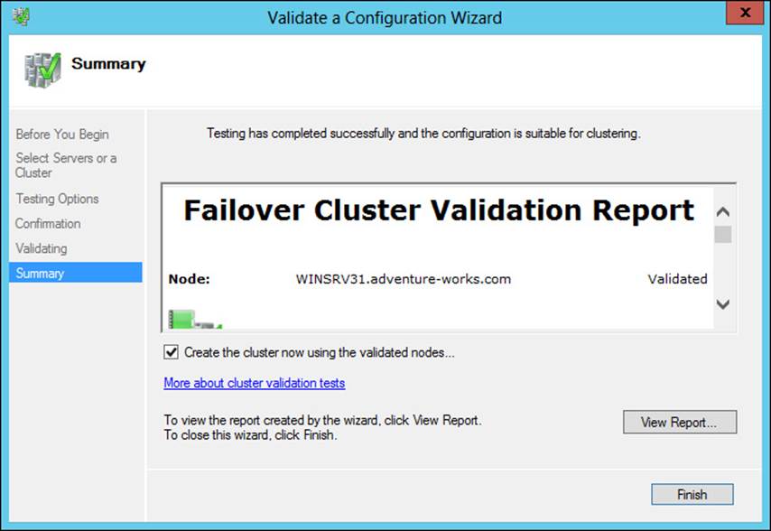
FIGURE 2-1 Viewing a Failover Cluster Validation Report
When possible, the server hardware in a cluster should match. This helps to alleviate some management overhead in trying to balance different performance levels on different hardware. Multi-site clusters should have an even number of nodes and should use the Node and File Share Majority option for the cluster.
More Info: Network and Storage for Clusters
See http://technet.microsoft.com/en-us/library/jj612869.aspx for more information on network and storage options for clusters.
Global Update Manager (GUM) is used to communicate updates about a cluster to the cluster nodes. In Windows Server 2012, GUM uses an All (write) and Local (read) mode, which requires that all cluster nodes receive and process an update in order for the change to be committed. However, as of Windows Server 2012 R2, you can also configure a mode called Majority (read and write), which requires that a majority of clusters receive and process the update rather than all nodes. Hyper-V failover clusters use this mode as the default in Windows Server 2012 R2. Another mode called Majority (write) and Local (read) is also available; it uses the majority receive and process, but on database reads the local node doesn’t compare the timestamp.
 Exam Tip
The DatabaseReadWriteMode property of the Get-Cluster cmdlet is available to set and view the current value for the GUM mode. A value of 0 corresponds to All (write) and Local (read), a value of 1 indicates Majority (read and write), and a value of 2 indicates Majority (write) and Local (read) mode.
Microsoft recommends using All (write) and Local (read) for clusters that require consistency, such as when running a clustered Exchange server.
Understanding design considerations
Many design considerations for clusters are simply best practices for network redundancy, such as eliminating single points of failure and so on. This section examines design considerations related to planning clustering.
Network redundancy and priority
Planning for network redundancy is a vital issue when providing a clustered service or application. The network layer can be made redundant by including multiple network adapters that are connected to separate networks or by building the redundancy at the network layer with multiple switches, routers, and so on. Most organizations will likely have some level of redundancy at the network layer already, so when analyzing solutions for providing network redundancy, it’s important to consider each and every point where failure might occur. Having two or more network adapters will provide minimum redundancy, and cluster nodes connected to the same network will also pass the redundancy check in the Cluster Configuration Wizard. However, for true redundancy, not only should the network adapters be made redundant and connected to different network hardware, but other adapters, such as those used for iSCSI connections, should also be made redundant.
Clusters can use multiple networks, including those dedicated for cluster traffic. This is configured within the properties of a given network, as shown in Figure 2-2.
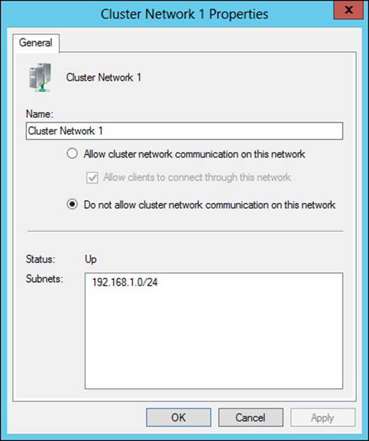
FIGURE 2-2 Network properties within a cluster
You can configure the priority of the network to use for Hyper-V live migrations. This is accomplished in the Live Migration Settings dialog box, which is found within the Networks area of the Failover Cluster Manager (see Figure 2-3).
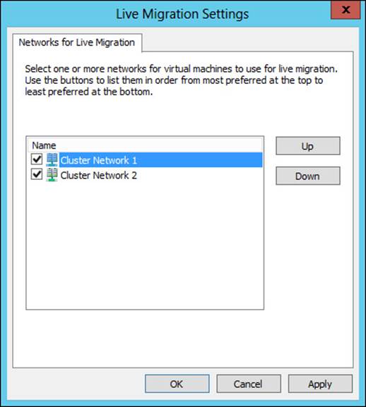
FIGURE 2-3 Live migration network settings
More Info: Further Tuning
See http://blogs.msdn.com/b/clustering/archive/2012/11/21/10370765.aspx for more tuning information for cluster networking.
Resource failover and failback
Resource failover and failback are configured within the core Cluster Group Properties dialog box, shown in Figure 2-4.
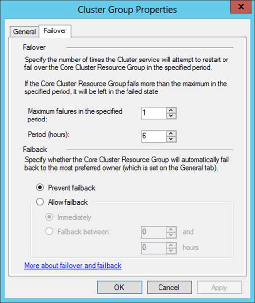
FIGURE 2-4 Configuration settings for failover and failback
Failover settings determine how many times the service can fail within the specified time period. For example, Figure 2-4 shows a configuration where the service can fail only once within a six-hour period. If the service fails a second time, it won’t be restarted.
Failback determines when the service will transfer to its preferred owner after a failure, with the default being to prevent failback, as shown in Figure 2-4.
Heartbeat and DNS settings
Heartbeat and DNS settings for a cluster are configured with Windows PowerShell cmdlets. You can view current settings using the following command:
Get-Cluster | Format-List -Property *
When you run that cmdlet, you’ll get several lines of output. Within the output, the settings related to heartbeat include:
![]() SameSubnetDelay
SameSubnetDelay
![]() SameSubnetThreshold
SameSubnetThreshold
![]() CrossSubnetDelay
CrossSubnetDelay
![]() CrossSubnetThreshold
CrossSubnetThreshold
Setting these parameters affects the amount of delay and the time limits for heartbeat communication between cluster nodes. The default behavior is five missed heartbeats before a failover occurs.
Additional parameters can be found with the Get-ClusterResource and Get-ClusterParameter combination, like so:
Get-ClusterResource | Get-ClusterParameter
Many of the cluster properties can be changed. For example, the HostRecordTTL property can be changed from its default, 1200, to a lower value, such as 60. You’d do this so that a change in the hostname to IP address would propagate faster. Here’s an example of changing that value:
Get-ClusterResource | Set-ClusterParameter -Name HostRecordTTL -Value 60
Exam Tip
The HostRecordTTL value can then be verified with the previously shown command to retrieve the DNS-related parameters.
More Info: Windows PowerShell cmdlets
See http://technet.microsoft.com/en-us/library/ee461009.aspx for information on the cluster-related Windows PowerShell cmdlets.
Quorum configuration
Quorum defines the voting nodes or elements that need to be active for the cluster to continue operations (or start). You can add a witness that also gets a Quorum vote, and you can configure the voting properties for nodes. You configure the Quorum based on the number of nodes and the site topology, but you should also consider the available network bandwidth and reliability between nodes, as well as the available resources and the priority of each node in the cluster. Ideally, there will be an odd number of voting nodes for a cluster. If you’ll be using an even number of nodes in the cluster, you can configure a witness, either disk or file share, as long as the nodes can access the witness, and a Quorum witness should always be configured with Windows Server 2012 R2 clusters.
For dynamic Quorum clusters in Windows Server 2012 R2, the witness vote is changed based on the number of voting nodes in the cluster. If the number of voting nodes is even, then the witness has a vote.
Table 2-1 contains considerations for witness configuration.
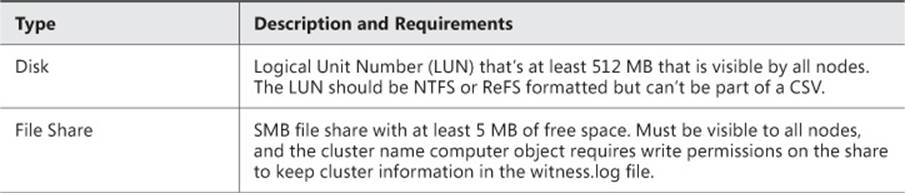
TABLE 2-1 Witness configuration
Disk witness types are typically found in single site clusters, while file share witness types are helpful for multi-site clusters. Also, a disk witness will store a copy of the cluster database while a file share witness will not.
Quorum configuration is automatically done based on the number of nodes and shared storage available at the time of cluster creation. However, you may want to change the Quorum configuration in certain circumstances, such as:
![]() Long-term node or witness failure
Long-term node or witness failure
![]() Addition or removal of nodes
Addition or removal of nodes
![]() Addition or removal of storage
Addition or removal of storage
![]() Multi-site cluster recovery
Multi-site cluster recovery
Quorum can be configured through the Configure Cluster Quorum Wizard. When configuring Quorum you can choose from three methods as shown in Figure 2-5.
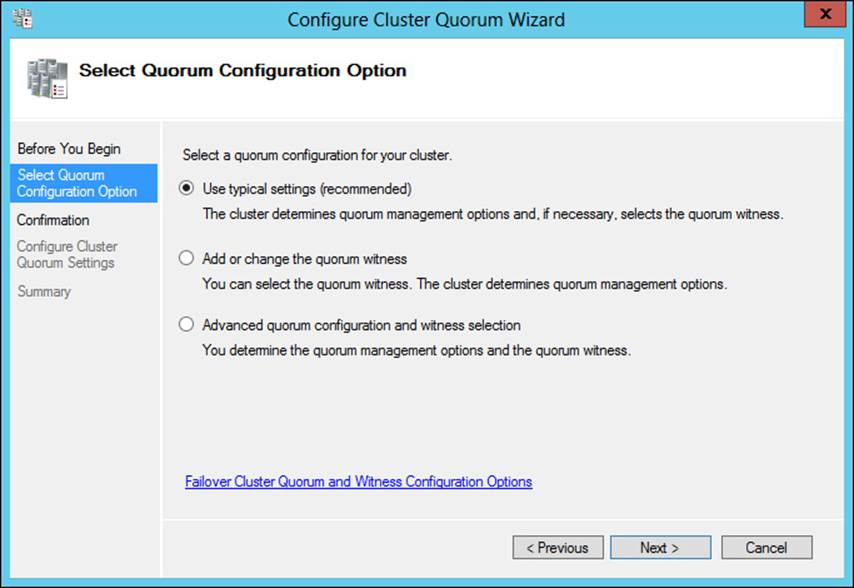
FIGURE 2-5 Configuring Quorum
Selecting either of the options other than Use Typical Settings (Recommended) enables you to change the configuration. For example, you can add a disk or file share witness, as shown in Figure 2-6. Using the Advanced Quorum Configuration and Witness Selection option, you can configure voting configuration and Quorum management and add a disk or file share witness.
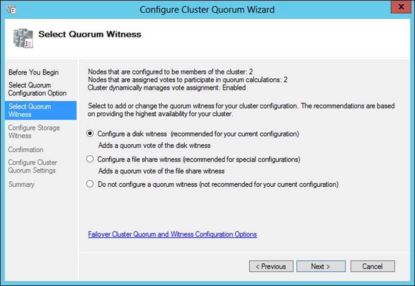
FIGURE 2-6 Configuring witness settings for a cluster
Quorum is configured in three modes, as described in Table 2-2.
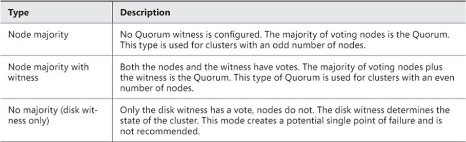
TABLE 2-2 Quorum configuration
Windows Server 2012 enables dynamic Quorum management, which manages the voting rights for a node based on its status. When a node leaves the active cluster, dynamic Quorum management removes its vote.
The current voting status of a cluster node can be verified by looking for a value of 1 for the DynamicWeight property when running Get-ClusterNode through Windows PowerShell. Other Windows PowerShell cmdlets are helpful for cluster management, including using the Get-ClusterQuorum cmdlet and running Test-Cluster to perform the Validate Quorum Configuration test.
Another new feature of Windows Server 2012 R2 is forced Quorum resiliency. The /fq switch, when added to the start parameters of the cluster service, is useful for partitioned or “split brain” clusters. Quorum resiliency causes detection of cluster partitions as they’re brought back online.
More Info: Quorum Configuration
See http://technet.microsoft.com/en-us/library/jj612870.aspx for more information on Quorum configuration.
Storage placement and replication
There are several options for storage in a cluster scenario. However, the storage needs to be compatible with Windows Server 2012. Storage should be Serial Attached SCSI (SAS), Fibre Channel, FCoE, or iSCSI. When using iSCSI, a network adapter should be dedicated to the iSCSI traffic, and teaming is not supported for iSCSI (though MPIO is).
When directly attached, storage should be configured on multiple disks (LUNs), including the disk witness if one is used. Additionally, basic disks should be used, and they should be formatted as NTFS. Or, if they are configured as CSV, then the volume needs to be NTFS-formatted.
Replication is especially important in a multi-site cluster. Some organizations will have replication configured at the disk or LUN level through the SAN. When the bandwidth is available between sites, synchronous replication can be used. Otherwise, for low-bandwidth or high-latency cluster scenarios, asynchronous replication would likely be more appropriate.
More Info: Storage Requirements and CSV
See http://technet.microsoft.com/en-us/library/jj612869.aspx for hardware and storage requirements and http://technet.microsoft.com/en-us/library/jj612868.aspx for information on the use of CSV in a cluster.
Cluster Aware Updating (CAU)
Cluster Aware Updating (CAU) is a new feature with Windows Server 2012 that enables clustered services to be updated while maintaining service availability with minimal disruption. Without CAU, the servers taking part in a cluster might be taken offline simultaneously to apply software updates. However, with CAU, the process is automated and follows these basic steps:
1. Place a node in maintenance mode.
2. Move clustered role service off of the node.
3. Install updates and restart if necessary.
4. Place the node back into service.
5. Restore clustered role service on the node.
6. Begin the update process on the next node.
Note: Failover Clustering
CAU is installed as a Windows feature called failover clustering.
An important distinction between updating with CAU and updating with other methods is that using CAU for updating involves using the Cluster Aware Updating tool or using a Windows PowerShell CAU plug-in.
More Info: CAU plug-ins
See http://technet.microsoft.com/en-us/library/jj134213.aspx for more information on how CAU plug-ins work.
Using other methods for updates is not recommended and can lead to service downtime. CAU integrates with an existing update’s infrastructure and can apply both Microsoft and non-Microsoft updates.
CAU operates in two modes, self-updating or remote-updating. In self-updating mode, the cluster updates itself according to the default Updating Run profile or by using a custom Updating Run profile. In remote-updating mode, the Update Coordinator computer (running Windows Server 2012 or Windows 8) starts the update process.
When planning CAU, the failover clustering feature is required on each node of the cluster. The CAU clustered role and failover clustering tools are required on all nodes for self-updating mode. For remote-updating mode, the failover clustering tools are required on the remote updating computer and on cluster nodes that run the Save-CauDebugTrace PowerShell cmdlet. The CAU clustered role is not required for remote-updating mode.
More Info: CAU
See http://technet.microsoft.com/library/hh831694.aspx for more information on CAU and http://technet.microsoft.com/en-us/library/jj134234.aspx for requirements and best practices for CAU.
 Thought experiment: Configuring a Quorum for clusters
In the following thought experiment, apply what you’ve learned about this objective to predict what steps you need to take. You can find answers to these questions in the “Answers” section at the end of this chapter.
In this thought experiment, you’ll be configuring a cluster with four servers to balance a DHCP configuration. Two of the servers are located in a remote data center. You need to configure a proper Quorum configuration for the cluster.
Describe the options for Quorum configuration and where those options are configured.
Objective summary
![]() Multi-node and multi-site clustering is provided by failover clustering in Windows Server 2012.
Multi-node and multi-site clustering is provided by failover clustering in Windows Server 2012.
![]() When configuring multi-site clustering, heartbeat settings can be important when there’s network latency.
When configuring multi-site clustering, heartbeat settings can be important when there’s network latency.
![]() Quorum should have an odd number of voting nodes when possible, and a witness can be added to make an odd number of votes.
Quorum should have an odd number of voting nodes when possible, and a witness can be added to make an odd number of votes.
![]() Replication for storage can be used in a synchronous or an asynchronous manner, with synchronous being recommended for low-latency, high-bandwidth clusters.
Replication for storage can be used in a synchronous or an asynchronous manner, with synchronous being recommended for low-latency, high-bandwidth clusters.
Objective review
Answer the following questions to test your knowledge of the information in this objective. You can find the answers to these questions and explanations of why each answer choice is correct or incorrect in the “Answers” section at the end of this chapter.
1. Which of the following commands shows IP and networking information specific to a cluster?
A. Get-ClusterInfo
B. Get-ClusterResouce | Get-ClusterParameter
C. ifconfig /cluster
D. Get-ClusterNetworkInfo
2. Which Quorum type prevents voting by all nodes except the witness?
A. Node Majority (Witness Voting)
B. Node Majority (Disk Witness)
C. No Majority (Disk Witness Only)
D. No Majority (Witness Vote Only)
3. Which of the following is not a valid reason for changing Quorum configuration?
A. Long-term node or witness failure
B. Adding or removing nodes
C. Temporary failure of a network switch
D. Multi-site cluster recovery
Objective 2.2: Plan and implement highly available network services
The second objective looks at creating a fault-tolerant environment at the network level. This is important to understand because networking is a key concept in an enterprise-level system administrator toolkit.
This objective covers how to:
![]() Plan for and configure Network Load Balancing (NLB)
Plan for and configure Network Load Balancing (NLB)
![]() Understand design considerations, including fault-tolerant networking, multicast versus unicast configuration, state management, and automated deployment of NLB using Virtual Machine Manager service templates
Understand design considerations, including fault-tolerant networking, multicast versus unicast configuration, state management, and automated deployment of NLB using Virtual Machine Manager service templates
Planning for and configuring Network Load Balancing
Network Load Balancing (NLB) provides a means to distribute network traffic across two or more servers (up to 32 total), known as hosts in NLB terminology. NLB provides redundancy and scalability for basic stateless services, such as HTTP. NLB uses one or more cluster IP addresses to enable network traffic to the cluster.
NLB is added as a server feature in the Add Roles and Features Wizard. Doing so installs the Network Load Balancing Manager. Additionally, you can manage NLB using Windows PowerShell cmdlets.
More Info: NLB Overview
See http://technet.microsoft.com/en-us/library/hh831698.aspx for an overview of the NLB technology. While much of NLB has remained the same from Windows Server 2008, some of the management aspects have changed.
Creating a new NLB cluster involves selecting New from the Cluster menu in the Network Load Balancing Manager. Doing so invokes the New Cluster Wizard. Within the New Cluster Wizard, enter the name of a host that will be part of the cluster and click Connect to reveal the available network adapters for the cluster, as shown in Figure 2-7.
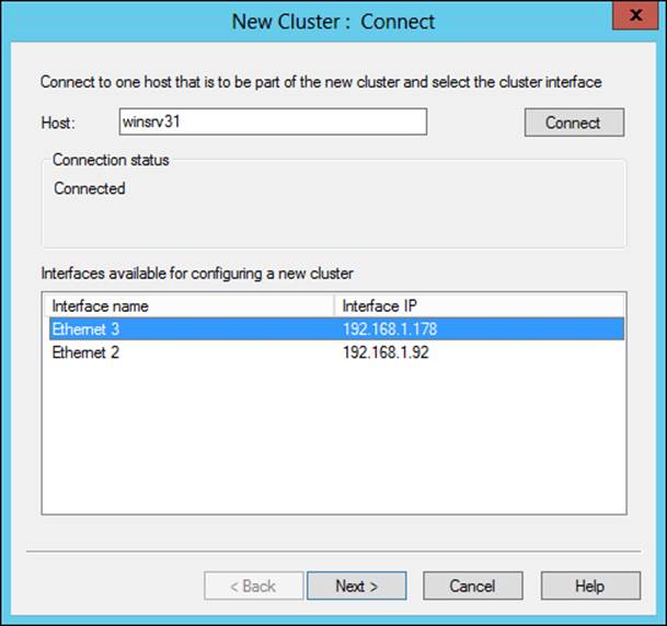
FIGURE 2-7 The New Cluster Wizard for creating an NLB cluster
The Host Parameters page will be shown next, within which you can add an IP address for the host by clicking Add. Doing so reveals the Add IP Address dialog box, shown in Figure 2-8.
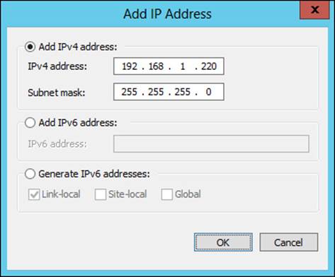
FIGURE 2-8 Adding an IP address to an NLB host
The Host Parameters page is shown in Figure 2-9. On this page, you can configure the host priority, whether the host state will remain suspended when the computer restarts, and its default state from among three choices:
![]() Started
Started
![]() Stopped
Stopped
![]() Suspended
Suspended
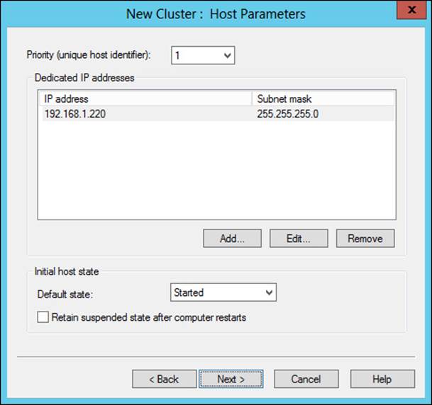
FIGURE 2-9 Host parameters for an NLB host
The Cluster IP Addresses page is shown next, within which you can configure the IP address(es) that will be used by clients connecting to the cluster. Figure 2-10 shows a cluster IP address that has been added by first clicking Add, which reveals a dialog box similar to that in Figure 2-8.
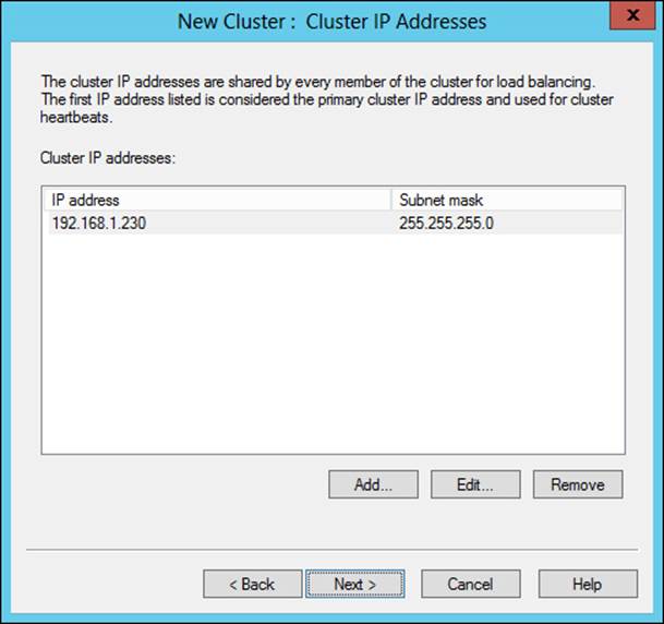
FIGURE 2-10 Configuring a cluster IP address
Cluster parameters are configured next, as shown in Figure 2-11.
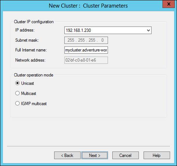
FIGURE 2-11 Configuring cluster parameters
On the Cluster Parameters page, you can configure the Full Internet Name for the cluster, along with its Cluster Operation Mode: Unicast, Multicast, or IGMP Multicast.
Port rules are configured on the Port Rules page, shown in Figure 2-12.
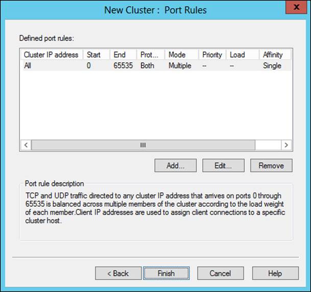
FIGURE 2-12 Configuring port rules for an NLB cluster
The default port rules direct all TCP and UDP traffic to the cluster (ports 0 through 65535). You can use this page to configure which ports will be allowed for the particular service being clustered. For example, if you’re configuring web traffic, you can typically remove or edit the default rule and in its place add a rule to allow TCP ports 80 and 443 (if HTTPS is used) to the cluster IP address.
More Info: Service Ports and Protocols
Technically, UDP ports 80 and 443 are reserved for HTTP traffic as well. See http://www.iana.org/assignments/service-names-port-numbers/service-names-port-numbers.txt for the authoritative list of service ports and protocols.
The Add/Edit Port Rule dialog box, shown in Figure 2-13, is where you can map the IP address to the port, along with protocols, filtering, and affinity.
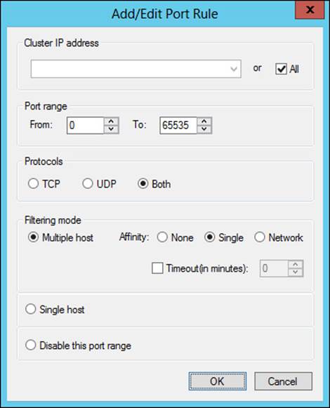
FIGURE 2-13 Configuring a port rule
Note: Understanding Design Considerations for NLB
When designing and planning an NLB implementation, you should consider the configuration of the hosts and the cluster as well.
Understanding design considerations
The next exam objective looks at some specific design-related aspects for creating a highly available network.
Fault-tolerant networking
NLB requires only a single network adapter, and each host participating in the cluster can have a different number of adapters. IP addresses on the adapters used for NLB need to be static, and NLB will disable DHCP on network adapters assigned to the cluster.
By itself, NLB provides for fault tolerance when more than one host is used. Hosts need to be on the same subnet. However, being on the same subnet many times implies that the hosts may connect to the same physical network hardware. Therefore, a single point of failure exists when hosts in an NLB cluster are connected in such a way. Adding fault tolerance at this level means adding redundant network hardware to reduce or remove the single point of failure and provide fault tolerance at the network level.
The filtering mode of a cluster, which is set at the port rule level, defines how network traffic is handled within the cluster. There are three options:
![]() Multiple Hosts
Multiple Hosts
![]() Single Host
Single Host
![]() Disable This Port Range
Disable This Port Range
Multiple Hosts filtering mode indicates that cluster traffic will be distributed across multiple hosts in the cluster. Single Host filtering mode sends traffic for the given port rule to a single host based on its priority. If you choose Disable This Port Range, traffic will be blocked to the cluster IP address for the specified ports.
Multicast vs. unicast configuration
You can configure multicast and unicast settings at cluster creation or later by using the Cluster Parameters tab of the cluster Properties dialog box, shown in Figure 2-14.
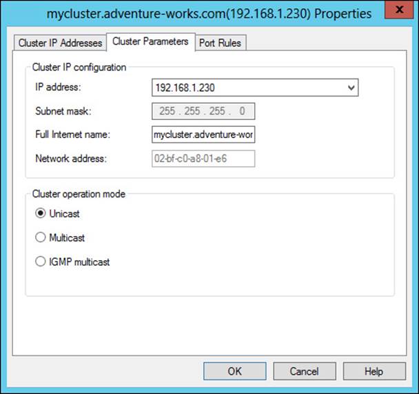
FIGURE 2-14 Cluster parameters related to unicast and multicast
In unicast mode, which is the preferred mode when there are two or more network adapters in a host, all traffic (for the configured ports) received on the cluster IP address is sent in a unicast manner to each of the hosts in the cluster. To do so, NLB will overwrite the MAC address of the adapter participating in the cluster with the cluster MAC address. This means that the network adapter must allow its MAC address to be changed. Unicast is appropriate when there’s more than one network adapter in the host.
When using unicast, the MAC address is made unique for outbound packets so as not to create problems when a switch sees the same MAC address through different ports. This modification is based on the host’s priority. Even so, switch floods are still possible with unicast.
Multicast should be used when communication between the hosts is required and there’s only one adapter in each host. The adapter MAC address is not overwritten with multicast mode, and each host receives cluster traffic using the multicast MAC address. However, a static Address Resolution Protocol (ARP) entry may be necessary for multicast to work correctly.
State management
State management refers to the maintaining of session state that’s necessary for certain applications. For example, a web application where the user logs in will typically have a session associated with it. That session may be tied to the server.
NLB handles state through the affinity parameter, which is part of the port rules for a cluster. The affinity, configured as None, Single, or Network, defines how a session is handled. However, affinity is applicable only when the multiple-host filtering method is selected.
Selecting None for affinity indicates that connections, even from the same client IP address, can be handled by different hosts in the cluster. When Single affinity is chosen (the default), requests from the same client IP address are sent to the same NLB cluster host. Finally, the Network affinity option directs all traffic from a given Class C subnet to a specific cluster host. The Network affinity option is especially helpful if there are multiple exit points from a client location (such as multiple proxies) that would cause a single client’s IP address to appear to be from a different source.
Note: State Management
Selecting None for affinity improves performance of the cluster but doesn’t provide any state management. Selecting Single or Network provides state management because each client request is sent to the same host.
Automated deployment of NLB using Virtual Machine Manager service templates
System Center 2012 Virtual Machine Manager (VMM) service templates can be used to deploy NLB. Doing so requires a Virtual IP (VIP) template for NLB.
More Info: VIP Templates
VIP template creation is beyond the scope of this section. See http://technet.microsoft.com/en-us/library/hh831698.aspx for more information on this process.
The basic process for creating service templates in VMM involves using Service Template Designer to add the features necessary for the desired configuration. One such feature is a load balancer, which can be added to the service template using the Add Load Balancer button. Doing so adds a VIP connected to Client connection and Server connection objects. VMM will attempt to choose a VIP, but you can change the VIP by clicking on the object in Service Template Designer and selecting a different VIP.
With the correct VIP selected, you click on the Server connection object and, using the Connector, connect it to a NIC object for the appropriate host. Finally, the Client connection object is connected to a VM network. If the VM network hasn’t already been added, it can be added by using the Add VM Network button. The final configuration looks like Figure 2-15.
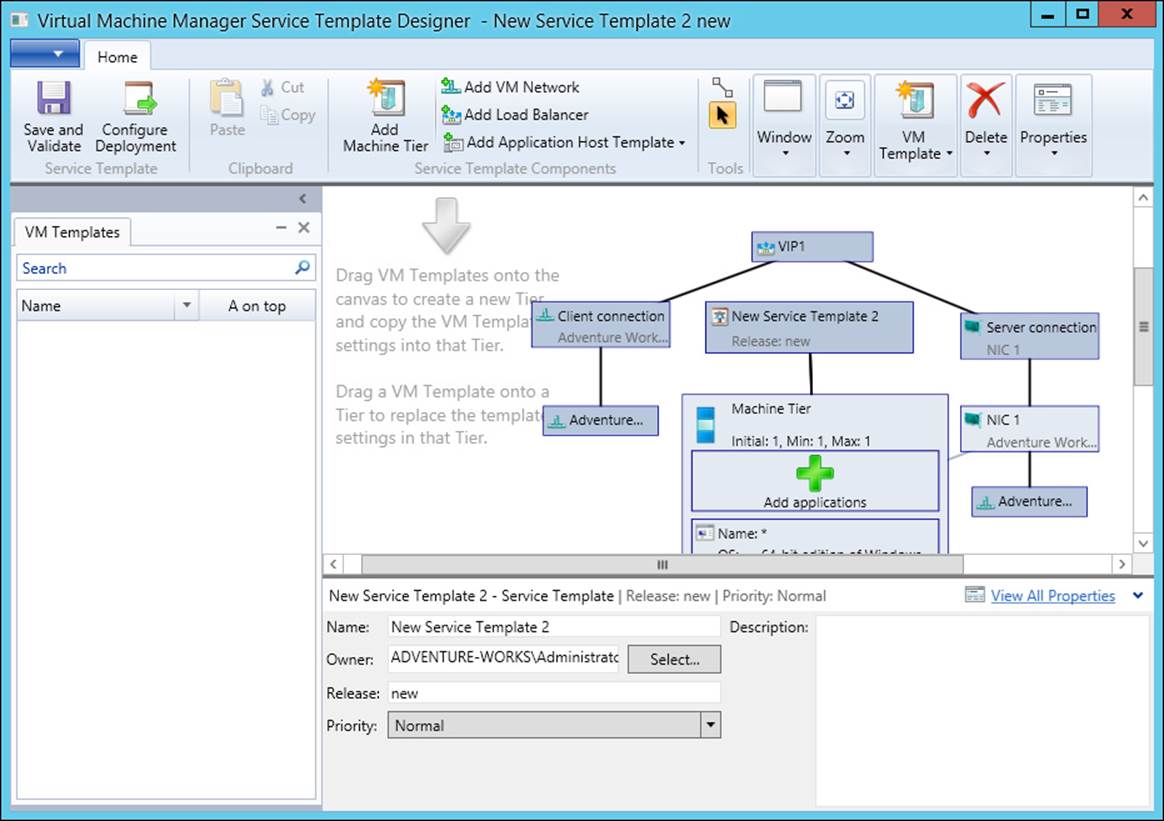
FIGURE 2-15 A service template with an NLB load balancer
Note: Machine Tier Operating System
The machine tier operating system needs to have the NLB feature installed
More Info: NLB and VMM
See http://technet.microsoft.com/en-US/library/hh335098.aspx for more information on adding NLB to a service tier. The exam objectives for Chapter 3 are almost solely centered around virtualization, so the service tier and VMM concepts may become clearer after that chapter as well.
Thought experiment: Using NLB for network redundancy
In the following thought experiment, apply what you’ve learned about this objective to predict what steps you need to take. You can find answers to these questions in the “Answers” section at the end of this chapter.
Your network is in need of redundancy for a web application, and you’ve chosen NLB for the solution. The servers involved in the web application each have one network adapter on the same subnet and are running Windows Server 2012. The web application needs to keep session state.
Describe the NLB configuration that you’ll use, focusing specifically on multicast or unicast configuration and session management.
Objective summary
![]() Fault tolerance can be provided at the network level or by choosing a filter mode, such as multiple hosts.
Fault tolerance can be provided at the network level or by choosing a filter mode, such as multiple hosts.
![]() State management is achieved by sending all traffic from a client IP address to a single host (Single mode) or from a client network (Network mode) to a single host.
State management is achieved by sending all traffic from a client IP address to a single host (Single mode) or from a client network (Network mode) to a single host.
![]() NLB handles state through an affinity parameter within the cluster rules.
NLB handles state through an affinity parameter within the cluster rules.
![]() NLB can be included as part of a VMM service template to make deployment easier. When using service templates, the operating system at the machine tier needs to have NLB installed.
NLB can be included as part of a VMM service template to make deployment easier. When using service templates, the operating system at the machine tier needs to have NLB installed.
Objective review
Answer the following questions to test your knowledge of the information in this objective. You can find the answers to these questions and explanations of why each answer choice is correct or incorrect in the “Answers” section at the end of this chapter.
1. Which of the following network affinity settings provides for state management?
A. Single
B. None
C. Session
D. Network
2. Which operation mode is appropriate when each host has more than one network adapter?
A. Single
B. Unicast
C. Multicast
D. Anycast
3. Which filter mode will send all traffic to a single host based on its priority?
A. Single Host
B. Multiple Hosts
C. Failover
D. Round-Robin
Objective 2.3: Plan and implement highly available storage solutions
High availability around storage is an area that has seen improvement in technology and support over the past decade. With standard tools and a small investment, you can create robust and scalable storage solutions for the enterprise. This section looks at a few ways you can make storage more redundant as it relates to the 70-414 exam objectives.
This objective covers how to:
![]() Plan for and configure storage spaces and storage pools
Plan for and configure storage spaces and storage pools
![]() Design highly available, multi-replica DFS Namespaces
Design highly available, multi-replica DFS Namespaces
![]() Plan for and configure multi-path I/O (MPIO)
Plan for and configure multi-path I/O (MPIO)
![]() Configure highly available iSCSI target and iSNS servers
Configure highly available iSCSI target and iSNS servers
![]() Plan for and implement storage using RDMA and SMB multichannel
Plan for and implement storage using RDMA and SMB multichannel
Planning for and configuring storage spaces and storage pools
Storage spaces and storage pools provide storage virtualization that brings another level of management and flexibility to Windows Server 2012. Storage pools, which are the underlying foundation of a storage space, use physical disks. Storage spaces provide a layer of abstraction to the physical infrastructure. Windows Server 2012 R2 adds several new features to storage spaces, including storage tiers, dual parity, and parity space for failover clusters, among others. Storage tiers improve performance by moving data to faster storage platforms, such as solid-state drives, based on the frequency of data access. Dual parity helps with resiliency in the event of a multi-disk failure by creating two copies of parity information. The parity space support for failover clusters enhances the use of storage spaces with failover clustering by enabling the creation of parity spaces.
More Info: New Features of Storage Spaces
See http://technet.microsoft.com/library/dn387076.aspx for more information on the new features of Storage Spaces in Windows Server 2012 R2.
Storagespaces require Serial Attached SCSI (SAS) or Serial Advanced Technology Attachment (SATA) disks with at least 4 gigabytes (GB) of available space that’s unformatted and not part of a volume. The limitations are as important as the requirements. You can’t use iSCSI or Fibre Channel controllers with storage spaces, and—while supported—USB disks are not recommended.
When planning storage spaces, you can choose from a simple, mirror, or parity resiliency. The resiliency type will determine the speed of the resulting data access as well as its resiliency to failure of a disk within the storage space. The resiliency is based on the disks available in the underlying storage pool. In other words, if the storage pool used as the basis for the storage space has only one disk, then the resiliency types will be limited.
Simple resiliency requires only one disk but doesn’t provide any data protection in the event of disk failure. With simple resiliency, data is striped across the physical disks. Simple resiliency provides higher performance at the cost of protection; therefore, if you choose simple resiliency, you need to ensure that the data can be re-created easily in the event of disk failure.
Mirror resiliency provides a level of protection against disk failure by mirroring data across disks in the storage space. Mirror resiliency requires at least two disks and is slower than simple resiliency because data must be written across multiple disks. When used with five or more disks, mirror resiliency can protect against two disk failures. Mirror resiliency is appropriate for most cases.
Parity resiliency requires at least three disks and stores data and parity information across the disks. Parity resiliency is appropriate for sequential access scenarios where data is read or written in a certain order, such as with a backup system.
Both parity and mirror resiliency reduce the amount of available space on the storage space because each resiliency type needs to store additional information on each disk.
More Info: Storage Spaces
See http://technet.microsoft.com/en-us/library/hh831739.aspx for an overview of Storage Spaces.
Creating a storage pool
Because storage spaces are composed of storage pools, you need to have a storage pool available to create a storage space. You can configure a storage pool through the File and Storage Services section of the Server Manager. Selecting Storage Pools and then New Storage Pool invokes the New Storage Pool Wizard, within which you can enter the storage pool name and disk subsystem, as shown in Figure 2-16.
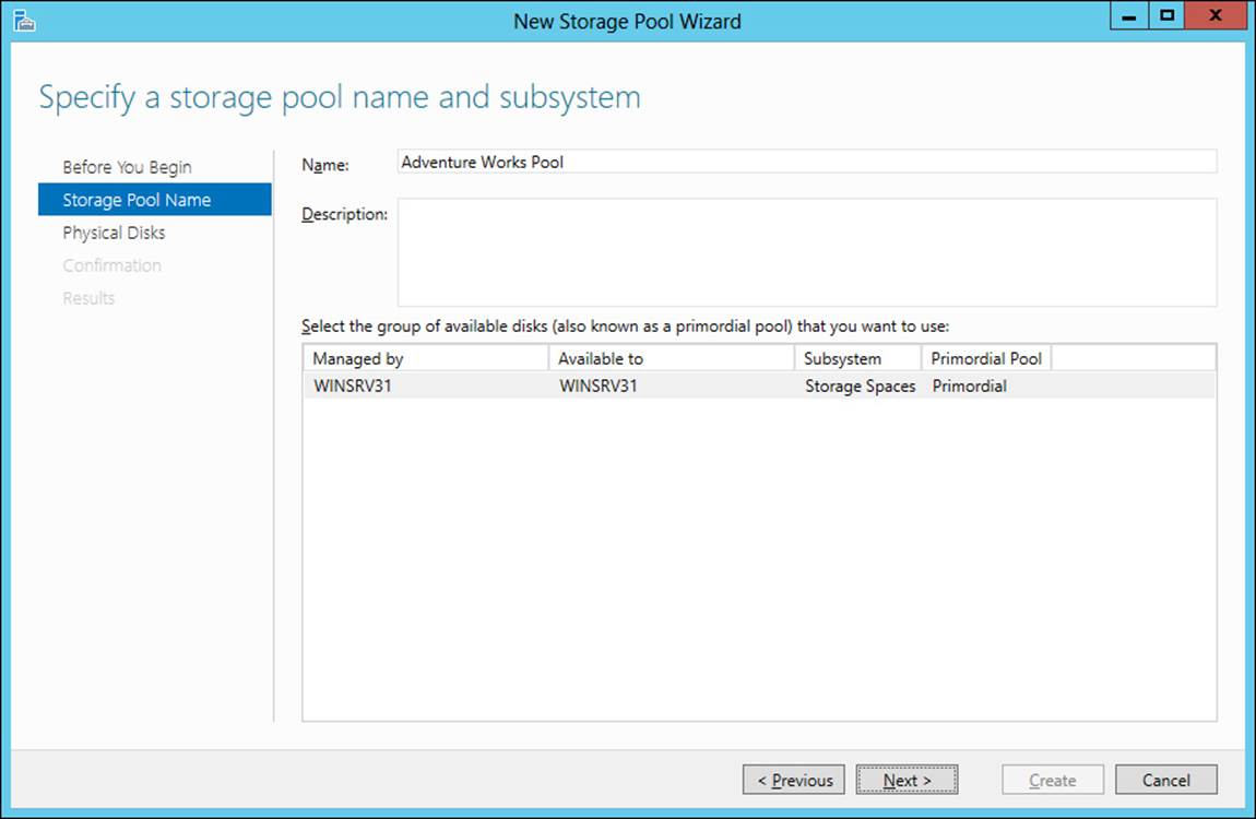
FIGURE 2-16 Configuring a storage pool
You can then select the physical disks to include as part of the storage pool, as shown in Figure 2-17.
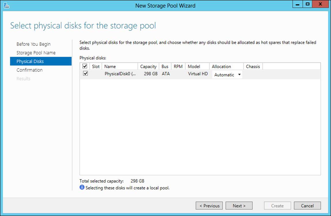
FIGURE 2-17 Selecting physical disks for a storage pool
The storage pool created in this section contains only one disk. Therefore, simple resiliency will be the only option available for the storage space. You can add another disk to the storage pool by selecting Add Physical Disk from the shortcut menu of the storage pool. Doing so reveals the Add Physical Disk dialog box, from which you can choose the disk to add to the storage pool.
Creating a storage space
Storage spaces are created by selecting New Virtual Disk from the shortcut menu of a storage pool. The New Virtual Disk Wizard walks through the process of creating a storage space. The first step in the wizard is to select a storage pool, as shown in Figure 2-18.
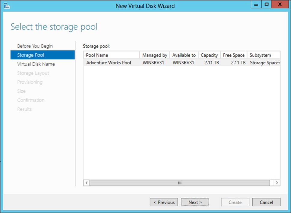
FIGURE 2-18 Creating a virtual disk
The name for the virtual disk is entered next, after which you choose the storage layout or resiliency type from among the choices discussed earlier in this section and depicted in Figure 2-19.
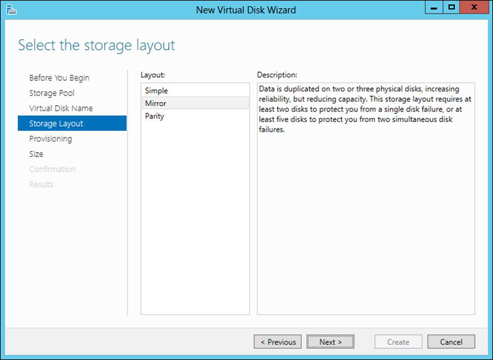
FIGURE 2-19 Choosing a resiliency type for a virtual disk
After choosing a resiliency type, the next step is to choose how the disk will be provisioned. You can choose Thin or Fixed, as shown in Figure 2-20. A thin provisioning type will use space only as needed, whereas fixed provisions the entire capacity right away.
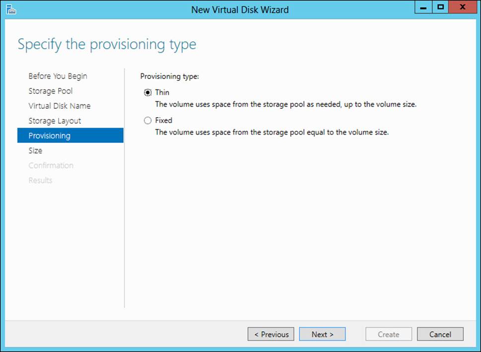
FIGURE 2-20 Choosing the provisioning type for a virtual disk
With thin provisioning, you can create a virtual disk that’s larger than the available capacity in the pool. You might do this if you know your storage needs will grow and you’ll be adding physical disks at a later date to meet the needs. This scenario is shown in Figure 2-21, where the virtual disk size is specified as 10 terabytes but the available capacity is only 2.11 terabytes. It’s worth noting that performance will be degraded with thin provisioning as opposed to fixed storage. Therefore, when provisioning a storage space where performance is a concern, you should use fixed storage.
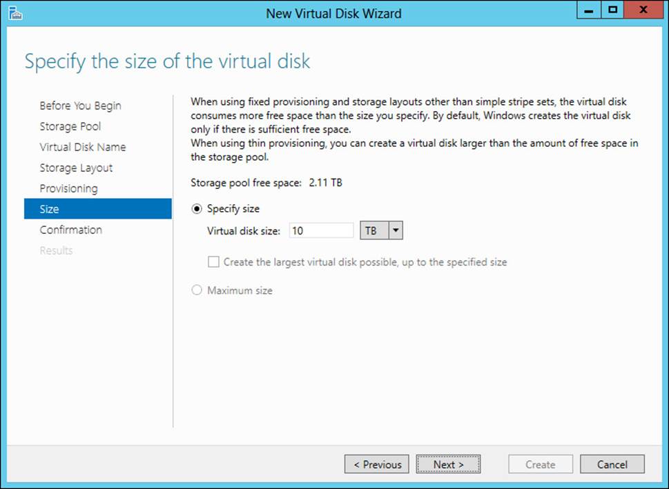
FIGURE 2-21 Setting the size of a virtual disk
Once the New Virtual Disk Wizard is complete, you’ll be given the option to create a new volume. If you select the option, the New Volume Wizard will open, within which you can create a new volume, as shown in Figure 2-22.
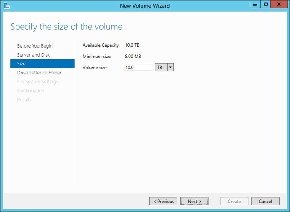
FIGURE 2-22 Creating a new volume
Other steps in the New Volume Wizard involve optionally choosing a drive letter for the volume and a format.
More Info: Deploying Storage Spaces
See http://technet.microsoft.com/en-us/library/jj822938.aspx for deployment steps for Storage Spaces, including Windows PowerShell cmdlets.
Designing highly available, multi-replica DFS Namespaces
Distributed File System (DFS) provides a means for sharing files and folders within an organization. DFS is made up of two features: DFS Namespaces (DFSN or DFS-N) and DFS Replication (DFSR or DFS-R). DFSN creates a common name for shared folders so that users can access the share using that name, regardless of where or on what server the shared folder is hosted. DFSR provides replication of folders between servers using Remote Differential Compression (RDC), which makes the replication process more efficient.
The exam objective indicates that this is a design-related objective as opposed to a management-based objective. Therefore, this section looks at high-level concepts related to using DFS as a solution. Included in the section are several configuration touch points that you should consider when designing DFS. See http://technet.microsoft.com/en-us/library/jj127250.aspx for an overview of DFS that contains additional links to management-related topics.
DFS is a good solution for distributed file shares between a central location and one or more remote sites. The shared folders are replicated across the wide area network (WAN) to the remote sites, and users, regardless of their location, can access the shared folder through its DFS Namespace. However, the servers involved in DFS need to be in the same Active Directory forest. Other notable requirements include the use of NTFS volumes for shared folder storage and the need for the Active Directory Domain Services (AD DS) schema to be Windows Server 2003 R2 or newer for read-write folders and Windows Server 2008 or newer for read-only folders.
When designing a DFS-based solution, you should consider the available bandwidth and peak usage times. DFS Replication traffic can be optimized to occur only during certain hours.
More Info: DFS Design
Though created for Windows Server 2003, the “Designing Distributed File Systems” document at http://technet.microsoft.com/en-us/library/cc772778 contains helpful information. It’s worth noting that configuration- and settings-related items may have changed since that document was written, and those settings are covered in this section.
DFS Namespace settings
When designing a namespace, you can create a standalone or domain namespace. Standalone namespaces can be clustered using a failover cluster and are also useful in environments where AD DS isn’t available. A domain-based namespace uses the domain name as the path of the namespace. This makes it easier to migrate the namespace server in the future. For example, a domain-based namespace will have a name like this:
\\adventure-works.com\Public
Conversely, a standalone namespace will have the server’s name in it:
\\WINSRV31\Public
When creating a domain-based namespace, you can optionally use Windows Server 2008 mode (enabled by default). When Windows Server 2008 mode is enabled, the Advanced tab of a domain-based namespace contains settings related to access-based enumeration, as shown in Figure 2-23. The polling settings shown in Figure 2-23 configure how the namespace servers will interact with the domain and are available for domain-based namespaces.
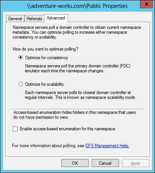
FIGURE 2-23 Configuring a domain-based namespace
If there are fewer than 16 namespace servers for the namespace, Optimize For Consistency should be used. The Optimize For Scalability option will cause an increase in the time it takes to replicate changes in a namespace, which may cause a temporary skew in the namespace view available to users.
Permissions can be configured when the namespace is created. By default, all users have read-only permissions. Other selections include:
![]() All Users Have Read And Write Permissions
All Users Have Read And Write Permissions
![]() Administrators Have Full Access; Other Users Have Read-Only Permissions
Administrators Have Full Access; Other Users Have Read-Only Permissions
![]() Administrators Have Full Access; Other Users Have Read and Write Permissions
Administrators Have Full Access; Other Users Have Read and Write Permissions
![]() Use Custom Permissions
Use Custom Permissions
In addition to configuring permissions, the Edit Settings dialog box shown in Figure 2-24 can be used to set the path for the shared folder.
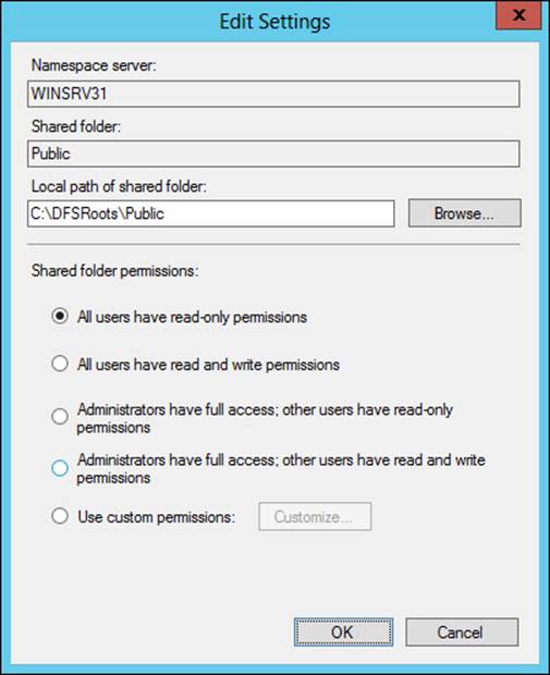
FIGURE 2-24 Changing settings for a namespace
When designing a namespace, you can also configure settings around referrals. When accessing a namespace, a user receives a list of namespace servers. If the first server in the list is unavailable, the client will attempt to reach the next server in the list. You can configure the length of time that the referral is cached, as well as the priority and ordering. Referral configuration is important for namespace design because the referral list can be set up to include only those servers at the client’s physical site to prevent clients from accessing servers across a WAN link.
Referral settings are configured on the Referrals tab of a namespace’s Properties dialog box, as shown in Figure 2-25. The default cache duration is 300 seconds. The ordering method options are:
![]() Random Order
Random Order
![]() Lowest Cost (default)
Lowest Cost (default)
![]() Exclude Targets Outside Of The Client’s Site
Exclude Targets Outside Of The Client’s Site
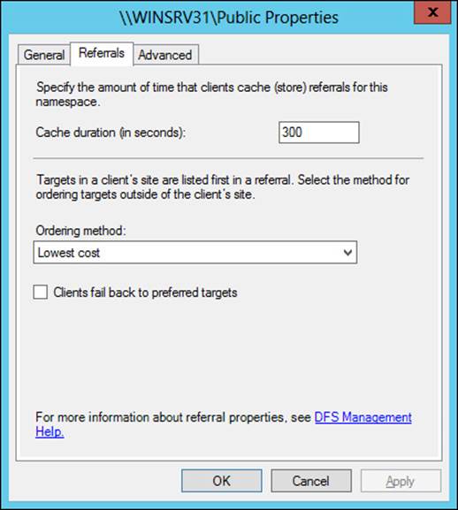
FIGURE 2-25 Configuring referral settings for a namespace
Additionally, you can configure whether clients will fail back to their preferred target server.
DFS Replication settings
DFS Replication is configured through replication groups. When creating a replication group, you can choose a multipurpose replication group or a replication group for data collection. The multipurpose replication group is a more generic approach and allows for two or more servers, whereas a data collection group is used for two servers and creates a two-way replication such that a branch (source) server sends its data to a central location (hub/destination server).
When creating a multipurpose replication group, there are three basic topologies, as described in Table 2-3.
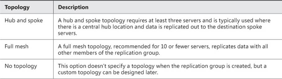
TABLE 2-3 Multipurpose DFSR topologies
When a topology is created, you can configure the hours within which replication will occur. The default is to replicate continuously using the full bandwidth (the default), as shown in Figure 2-26.
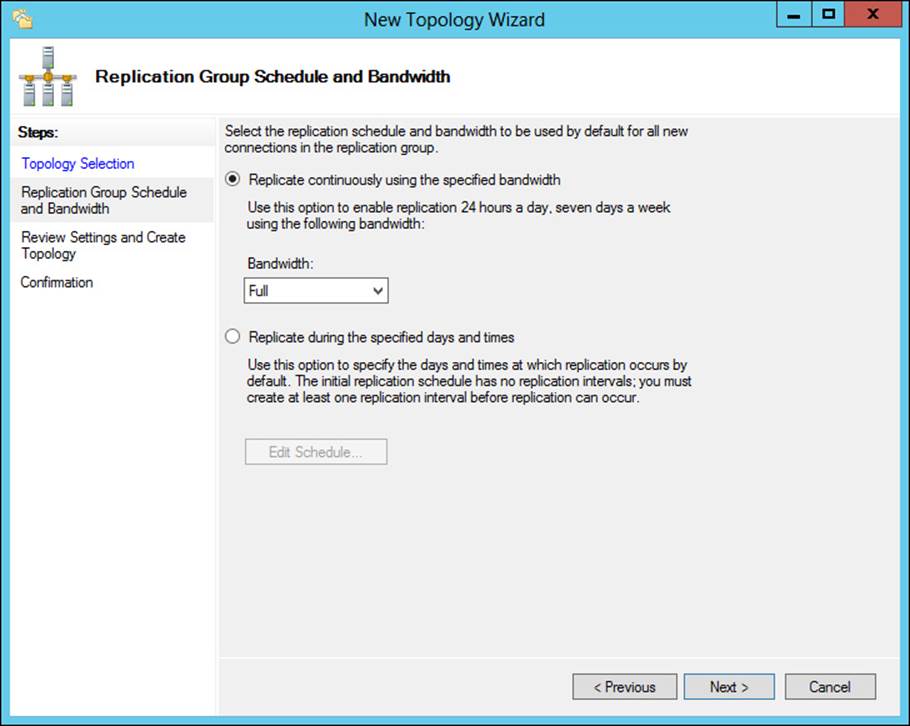
FIGURE 2-26 Configuring a replication group schedule
You can also configure a custom schedule for replication to occur, as shown in Figure 2-27.
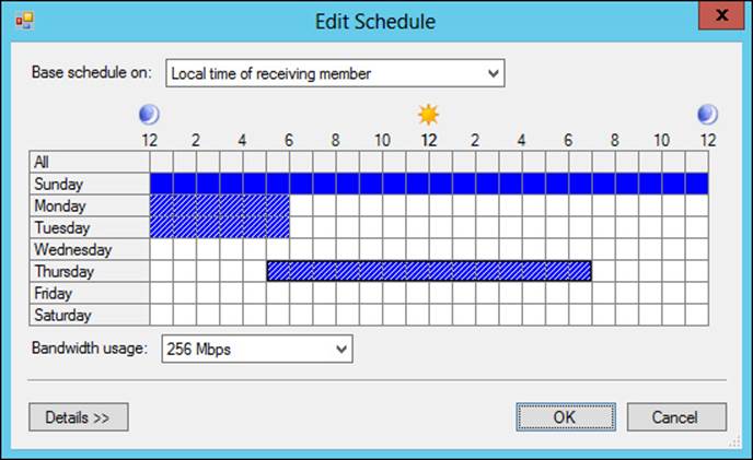
FIGURE 2-27 Configuring a custom replication schedule
When creating a replication group, you configure the folders to be replicated. When you do so, you can also publish the folder through DFS Namespace. This is accomplished within the Replicated Folders tab of a replication group’s workspace by selecting Share And Publish In Namespace. When you do this, the folder will use the namespace settings for the chosen namespace.
Planning for and configuring multi-path I/O (MPIO)
Multipath I/O (MPIO) is a means to provide high availability for storage connected to Windows servers. MPIO is typically used with a storage area network (SAN) scenario in an enterprise and provides multiple redundant connections to the SAN to ensure reliability.
MPIO relies on device-specific modules (DSMs) from vendors to interact with various storage providers. There’s also a Microsoft-provided DSM that works with SCSI Primary Commands-3 (SPC-3) compliant storage. MPIO is installed as a feature in Windows Server 2012 and is used with Fibre Channel, iSCSI, and SAS.
Windows uses Plug and Play (PnP) Manager for hardware detection, and MPIO also detects devices connected to a Windows server. When planning MPIO, the first step is typically determining whether the storage will be managed by the Microsoft DSM or a vendor DSM. The vendor DSM would need to support MPIO in order to be exposed through MPIO in Windows.
MPIO performs load balancing to increase throughput. When managed through the Microsoft DSM, there are several configurable policy settings for load balancing, as described in Table 2-4.
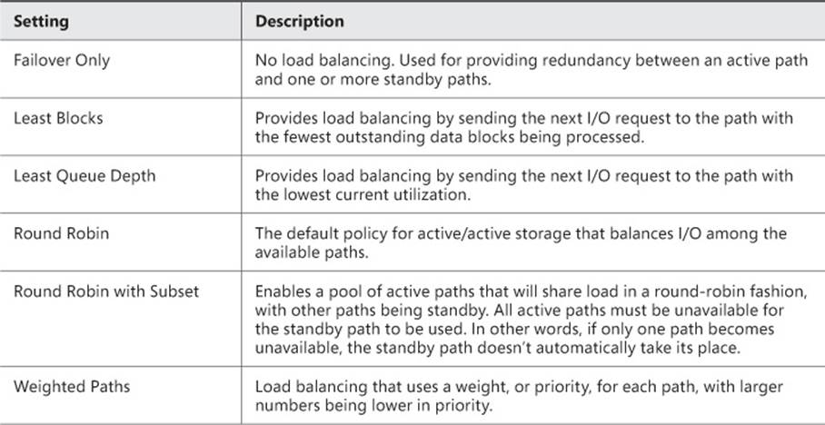
TABLE 2-4 Microsoft DSM settings
When using the graphical interface, MPIO is configured through the MPIO Properties dialog box, shown in Figure 2-28.
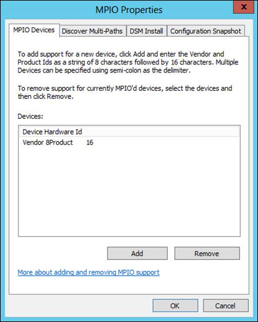
FIGURE 2-28 MPIO configuration through the graphical interface
The Discover Multi-Paths tab is where you can add multi-paths to the configuration.
When using the Server Core edition of Windows Server 2012, you configure MPIO through the command line. MPIO is added with the Windows PowerShell command as follows:
Enable-WindowsOptionalFeature -Online -FeatureName MultiPathIO
You can query the current state of the MPIO feature with this command:
Get-WindowsOptionalFeature -Online -FeatureName MultiPathIO
To enable the automatic claiming of iSCSI devices, use the following command:
Enable-MSDSMAutomaticClaim -BusType iSCSI
Changing the load balancing policy is achieved using the Set-MSDSMGlobalDefaultLoadBalancePolicy -Policy <PolicyAbbreviation> command, where the <PolicyAbbreviation> is one of the following:
![]() FOO Failover Only
FOO Failover Only
![]() LB Least Blocks
LB Least Blocks
![]() LQD Least Queue Depth
LQD Least Queue Depth
![]() None Removes the default load balance policy
None Removes the default load balance policy
![]() RR Round robin
RR Round robin
You can obtain the current load balance policy with the “get” version of the cmdlet:
Get-MSDSMGlobalDefaultLoadBalance -Policy
Various other settings for MPIO behavior are configured using the Set-MPIOSetting command. These include:
![]() CustomPathRecovery
CustomPathRecovery
![]() NewDiskTimeout
NewDiskTimeout
![]() NewPathRecoveryInterval
NewPathRecoveryInterval
![]() NewPathVerificationPeriod
NewPathVerificationPeriod
![]() NewPathVerificationState
NewPathVerificationState
![]() NewPDORemovePeriod
NewPDORemovePeriod
![]() NewRetryCount
NewRetryCount
![]() NewRetryInterval
NewRetryInterval
The Get-MPIOSetting cmdlet shows current values.
More Info: Windows PowerShell and MPIO Settings
See http://technet.microsoft.com/en-us/library/hh826113.aspx for a summary of the Windows PowerShell cmdlets available for MPIO and http://www.microsoft.com/en-us/download/details.aspx?id=30450 for the MPIO Users Guide.
Configuring highly available iSCSI target and iSNS servers
Internet Small Computer System Interface (iSCSI) and Internet Storage Name Service (iSNS) are means to discover, manage, and provide storage over a standard network interface and connection. iSCSI provides block-level storage through targets. iSCSI targets are connected to clients, known as initiators. Windows Server 2012 R2 can act as an iSCSI target server by adding it as a role service through the graphical interface or with the Add-WindowsFeature fs-iscsitarget-server command. Windows Server 2012 R2 can also act as an iSCSI initiator.
iSNS also uses the concept of clients and servers. The iSNS Server feature in Windows Server 2012 R2 helps to connect and manage discovery and use of iSCSI devices. See http://technet.microsoft.com/library/cc772568.aspx for more information on iSNS Server.
You can configure highly available iSCSI and iSNS servers using failover clustering in Windows Server 2012 R2. The iSCSI target server is installed as part of the File and Storage Services role, and failover clustering is installed as a feature.
Both iSCSI Target Server and iSNS Server are predefined roles in Failover Cluster Manager. As such, you can add them easily using the High Availability Wizard, shown in Figure 2-29. However, prior to running the wizard, you should configure the iSCSI disk as storage in Failover Cluster Manager. It’s worth noting that you’ll need to manually bring the disks online using the standard Windows disk management tools, through either Server Manager or Computer Management. Once the disk has been brought online, it needs to be added to the available storage for the cluster.
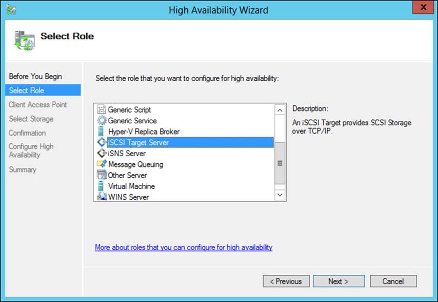
FIGURE 2-29 Configuring iSCSI Target Server for failover clustering
The client access point is configured next, as shown in Figure 2-30.
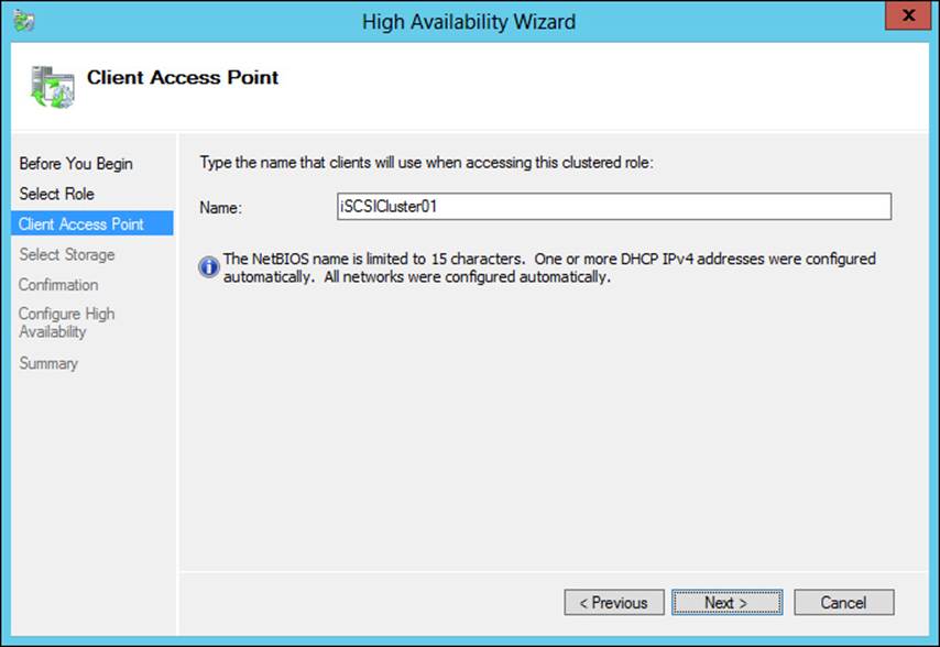
FIGURE 2-30 Setting the client access point
The storage previously added is selected next, after which you’ll configure the high availability for the iSCSI cluster.
Like iSCSI, the High Availability Wizard can assist with creation of a clustered iSNS server. The steps are essentially the same as those for configuration of iSCSI in Failover Cluster Manager.
Windows Server 2012 R2 updates the iSCSI Target Server role to increase the maximum number of sessions and logical units to 544 and 256, respectively. With iSCSI Target Server in Windows Server 2012 R2, you can also utilize Virtual Hard Disk (VHD) 2.0 formatted disks (.vhdx file extension).
More Info: iSNS
See http://technet.microsoft.com/en-us/library/cc772568.aspx for an overview of iSNS.
Planning for and implementing storage using RDMA and SMB multichannel
A new feature introduced in Windows Server 2012 is the ability to utilize network adapters that have the Remote Directory Memory Access (RDMA) feature. The RDMA feature enables a remote file share to act like a local one due to the increased ability of RDMA-capable adapters. RDMA is useful for improving performance of SMB-based file servers because it offloads processing onto the RDMA-capable adapter, thereby reducing CPU utilization and latency for SMB-based access. SMB multichannel detects RDMA-capable network adapters and enables the use of SMB Direct.
Though SMB Direct is enabled with Windows Server 2012 or Windows Server 2012 R2, it will only be used when the appropriate hardware is available. You can disable the use of RDMA for a given network adapter using the command
Disable-NetAdapterRdma <AdapterName>
Alternatively, RDMA can be disabled for all adapters on a given server with the command
Set-NetOffloadGlobalSetting -NetworkDirect Disabled
Exam Tip
Use Enable-NetAdapterRdma to enable RDMA for a given adapter or change the Network-Direct option to Enabled to enable RDMA for all adapters.
RDMA-capable network adapters shouldn’t be placed in a teamed configuration. Doing so will disable the RDMA capabilities. SMB Multichannel creates two RDMA connections per interface and can be used in a failover cluster configuration.
More Info: Deploying SMB Direct
See http://technet.microsoft.com/en-us/library/dn583825.aspx for more information on SMB Direct deployment on iWARP adapters, see http://technet.microsoft.com/en-us/library/dn583823.aspx for more information on deployment with InfiniBand adapters, and seehttp://technet.microsoft.com/en-us/library/dn583822.aspx for more information on SMB Direct with RoCE adapters.
 Thought experiment: Designing a DFS
In the following thought experiment, apply what you’ve learned about this objective to predict what steps you need to take. You can find answers to these questions in the “Answers” section at the end of this chapter.
You’re designing a distributed file access method that will span three physical office locations. The network runs AD DS, and there’s a domain controller located at each of the locations. There is a central data center and two remote offices in this organization. One of the concerns surrounds bandwidth usage for the replication and the subsequent usage of the shared file system.
Describe the configuration items that you can use with a distributed file system to limit or control bandwidth usage.
Objective summary
![]() Storage spaces provide a virtualized disk infrastructure built on storage pools of one or more disks.
Storage spaces provide a virtualized disk infrastructure built on storage pools of one or more disks.
![]() Storage spaces can be provisioned in a thin manner, giving them the ability to grow as needed.
Storage spaces can be provisioned in a thin manner, giving them the ability to grow as needed.
![]() DFS Namespaces and replication are used to create a virtualized disk share that’s accessible and replicated to multiple sites or locations if necessary.
DFS Namespaces and replication are used to create a virtualized disk share that’s accessible and replicated to multiple sites or locations if necessary.
![]() MPIO provides a method for accessing storage providers through multiple redundant and load-balanced paths.
MPIO provides a method for accessing storage providers through multiple redundant and load-balanced paths.
![]() You can configure MPIO to use the Microsoft DSM or a vendor-supplied DSM, assuming that the DSM meets MPIO certification requirements.
You can configure MPIO to use the Microsoft DSM or a vendor-supplied DSM, assuming that the DSM meets MPIO certification requirements.
![]() iSCSI Target Server and iSNS Server can be used as roles of failover clustering to provide redundancy and load balancing.
iSCSI Target Server and iSNS Server can be used as roles of failover clustering to provide redundancy and load balancing.
Objective review
Answer the following questions to test your knowledge of the information in this objective. You can find the answers to these questions and explanations of why each answer choice is correct or incorrect in the “Answers” section at the end of this chapter.
1. Which type of virtual disk resiliency requires three or more disks?
A. Simple
B. Parity
C. Mirror
D. Level 5
2. Which command would be used to change the load-balancing policy for MPIO to a policy that doesn’t include any load balancing but still provides for fail over?
A. Set-MPIOSetting -LoadBalancePolicy Failover
B. Set-MSDSMGlobalDefaultLoadBalancePolicy -Policy All
C. Set-MSDSMGlobalDefaultLoadBalancePolicy -Policy FOO
D. Set-MPIOSetting -Policy None
3. Which DFSR topology can be used with two servers?
A. Full mesh
B. Hub and spoke
C. Wheel
D. Dual-mesh
Objective 2.4: Plan and implement highly available server roles
A network doesn’t exist for itself alone; it exists for users to perform functions. That means providing services to support those functions. This section looks at methods in which server roles can be made highly available. This objective is largely a planning-related one, and the content reflects that requirement.
This objective covers how to:
![]() Plan for a highly available Dynamic Host Configuration Protocol (DHCP) server, Hyper-V clustering, Continuously Available File Shares, and a DFS Namespace server
Plan for a highly available Dynamic Host Configuration Protocol (DHCP) server, Hyper-V clustering, Continuously Available File Shares, and a DFS Namespace server
![]() Plan for and implement highly available applications, services, and scripts using Generic Application, Generic Script, and Generic Service clustering roles
Plan for and implement highly available applications, services, and scripts using Generic Application, Generic Script, and Generic Service clustering roles
Planning for highly available services
This exam objective looks at planning around providing high availability for various applications, including DHCP, Hyper-V, file shares, and DFSN. (Availability for DFSN was discussed in the previous section.) All of these services can be made highly available using failover clustering in Windows Server 2012, but in the case of DHCP, there are different options available beginning with Windows Server 2012.
DHCP
DHCP can be made highly available through failover clustering or by implementing a split scope. You can also configure a failover relationship within the DHCP Manager tool, which is a preferred approach for most organizations running Windows Server 2012.
The failover relationship created with DHCP Manager can be configured in a load balance or hot standby mode with an authorized server and for specific scopes. When creating the new failover relationship with DHCP Manager, you can set these and other parameters, as shown in Figure 2-31.
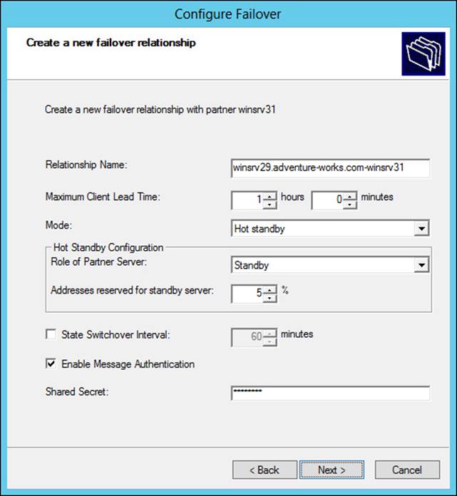
FIGURE 2-31 Configuring DHCP failover using DHCP Manager
When planning DHCP failover using this method, you should consider the amount of lead time that a server can provision an address before it needs to inform the other DHCP server (as defined by the Maximum Client Lead Time parameter). A longer amount of time means that the servers will be less likely to take over the entire scope in the event of a transient network issue or a quick reboot of one server. The State Switchover Interval is related insofar as it defines the amount of time that a server is marked as being down if it can’t be contacted.
Note that Figure 2-31 depicts the Role Of Partner Server as Standby mode (sometimes called Active/Passive). The other option is Load Balance (sometimes called Active/Active), which reveals a load balance percentage (50/50 default) that will be used by each server.
When planning other types of failover, such as through failover clustering, you should consider the shared storage that will be used within the cluster. That storage should be redundant or clustered so that DHCP will still be available in the event of a failure of one part of the storage.
Split-scope DHCP calls for the address scope for DHCP clients to be split among two or more servers. Those servers don’t share information with each other, but rather simply respond to DHCP queries as received. The obvious limitation is that there will be fewer addresses available on a given server because the scope of available addresses is split. This can cause problems in networks where there are limited available addresses.
Hyper-V clustering
Hyper-V uses failover clustering to provide redundancy. Doing so requires some amount of planning to ensure that prerequisites and configuration requirements are met. Aside from the hardware requirements for Hyper-V and failover clustering (see the More Info sidebar later in this section), you also need to use a virtual switch, CSV, and configure virtual machines for high availability.
Creation of virtual machines that are to be highly available should be done through Failover Cluster Manager. Creating virtual machines through Failover Cluster Manager ensures that the machines are configured for high availability.
More Info: Hyper-V Clustering
See http://technet.microsoft.com/en-us/library/jj863389.aspx for an overview of Hyper-V clustering, http://technet.microsoft.com/library/hh831531 for an overview of Hyper-V, and http://technet.microsoft.com/library/jj612869 for hardware requirements for failover clustering.
Continuously available file shares
File shares, available as the file server role in failover clustering, enable high availability of important files and data. When creating a highly available file server, you can choose between a clustered file server for general use (active/passive) or a scale-out file server (active/active). Choose a general file server for typical business-user patterns of opening and closing files regularly. Choose a scale-out file server for usage patterns that leave files open for long periods, such as for virtual machines.
General clustered file servers use one cluster node at a time, whereas scale-out file servers take advantage of the Distributed Network Name feature in Windows Server 2012 and distribute traffic across nodes. The use of CSVs will also determine the direction for the availability type. General file server clustering can’t use CSVs, but CSVs are required for the scale-out file server option.
Related to CSVs are the types of file systems and file system–related features supported by each type of file server clustering option, as described in Table 2-5.
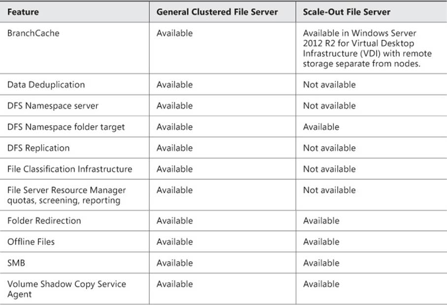
TABLE 2-5 Clustered file server support
More Info: Scale-out File Servers
See http://technet.microsoft.com/en-us/library/hh831349.aspx for more information on scale-out file servers.
DFS Namespace Server
DFS enables an organization to use shared folders in a distributed manner. DFS Namespace Server enables the virtualization of those folders so that users can interact with the folders without knowing the underlying server location or folder structure. DFS Namespace Server is one of the applications that can be made highly available through the High Availability Wizard.
See the section titled “Designing highly available, multi-replica DFS Namespaces” earlier in this chapter for more information on highly available DFS.
More Info: DFS Namespace Cmdlets
Windows Server 2012 adds Windows PowerShell cmdlets for DFS Namespace Server management. See http://technet.microsoft.com/en-us/library/jj884270.aspx for more details on those cmdlets.
Planning and implementing highly available applications, services, and scripts
Failover clustering includes generic roles titled Generic Application, Generic Script, and Generic Service. These are used to create clusters for services and applications that wouldn’t otherwise be aware of clustering or have options for high availability. To use a generic option, the underlying object being clustered should be IP-based, such as TCP, UDP, RPC over TCP/IP, DCOM, and so on.
The generic option chosen depends on the needs for clustering. For example, the Generic Application cluster simply looks to see whether a given process is running (and starts it if not). When configuring a Generic Application, you provide the application path and, optionally, registry keys to be replicated to other nodes. Like the Generic Application option, the Generic Service option looks to see whether the configured service is running and is used for service-related clustering. Also like the Generic Application, Generic Service clustering can replicate registry entries.
The Generic Script option gives some amount of control over the process but is more complex to configure. With a Generic Script, an administrator creates a script that controls underlying applications, including monitoring their state. The script then interacts with failover clustering to determine whether an underlying application should be restarted or failed over.
Generic clustering is implemented through Failover Cluster Manager by creating a cluster and then choosing the appropriate role from the High Availability Wizard.
 Thought experiment: Designing a DHCP failover solution
In the following thought experiment, apply what you’ve learned about this objective to predict what steps you need to take. You can find answers to these questions in the “Answers” section at the end of this chapter.
You’re designing a DHCP failover solution for a client with a small network running Windows Server 2012 servers and a combination of Windows 7 and Windows 8 client computers. The client currently uses a split-scope DHCP solution. The client uses basic NAS and local storage and doesn’t use virtual machines. The client has asked for an overview.
Describe the available solutions for DHCP failover and which one is recommended for this scenario.
Objective summary
![]() DHCP now has a native failover option that doesn’t have the same limitations as other methods, such as failover clustering and split scope.
DHCP now has a native failover option that doesn’t have the same limitations as other methods, such as failover clustering and split scope.
![]() File servers, Hyper-V, and generic services and applications can be clustered using failover clustering.
File servers, Hyper-V, and generic services and applications can be clustered using failover clustering.
![]() Continuously available file shares use the Distributed Network Name feature and CSVs to ensure high availability of file shares.
Continuously available file shares use the Distributed Network Name feature and CSVs to ensure high availability of file shares.
![]() Generic services, applications, and scripts enable failover clustering to work with applications and technologies that aren’t normally cluster-aware.
Generic services, applications, and scripts enable failover clustering to work with applications and technologies that aren’t normally cluster-aware.
Objective review
Answer the following questions to test your knowledge of the information in this objective. You can find the answers to these questions and explanations of why each answer choice is correct or incorrect in the “Answers” section at the end of this chapter.
1. Which type of DHCP failover mode is considered active/passive?
A. Standby
B. Load Balance
C. Passive Partner
D. Split Address
2. Which of the following file system features is supported on scale-out file servers?
A. SMB
B. BranchCache
C. Data Deduplication
D. File Classification Infrastructure
3. Which type of generic clustering enables you to choose registry keys to be replicated during the cluster role configuration? (Choose all that apply.)
A. Generic Application
B. Generic Script
C. Generic Service
D. Generic Registry Application
Objective 2.5: Plan and implement a business continuity and disaster recovery solution
The final objective in this area looks at disaster recovery and the technologies and methods for providing the same. Newly added for Windows Server 2012 R2 is Microsoft Azure Hyper-V Recovery Manager and System Center Data Protection Manager (DPM). Both of those additions are addressed in this section.
This objective covers how to:
![]() Plan a backup and recovery strategy
Plan a backup and recovery strategy
![]() Understand planning considerations, including how to:
Understand planning considerations, including how to:
![]() Recover an Active Directory domain and forest
Recover an Active Directory domain and forest
![]() Use Hyper-V Replica, including how to use Microsoft Azure Hyper-V Recovery Manager
Use Hyper-V Replica, including how to use Microsoft Azure Hyper-V Recovery Manager
![]() Restore and clone a domain controller
Restore and clone a domain controller
![]() Restore an Active Directory object and container using authoritative restore and the Recycle Bin.
Restore an Active Directory object and container using authoritative restore and the Recycle Bin.
![]() Plan for and implement backup and recovery using System Center Data Protection Manager (DPM)
Plan for and implement backup and recovery using System Center Data Protection Manager (DPM)
Planning a backup and recovery strategy
Windows Server Backup can be installed as a feature in Windows Server 2012. You can back up locally or online to Microsoft Azure. When planning a backup and recovery strategy, you should consider several items, as described in this section.
When designing a backup solution, consider what you’ll be backing up and where it will be sent.
![]() Do you need to back up the entire operating system? Doing so will include a significant amount of data that could possibly be re-created by reinstalling the operating system and then restoring data.
Do you need to back up the entire operating system? Doing so will include a significant amount of data that could possibly be re-created by reinstalling the operating system and then restoring data.
![]() How long will the backup take? You should ensure that the backup can complete before being kicked off again and that it doesn’t run during times when the server is heavily loaded. Incremental backups can help with this issue.
How long will the backup take? You should ensure that the backup can complete before being kicked off again and that it doesn’t run during times when the server is heavily loaded. Incremental backups can help with this issue.
![]() Where will backups be stored? If you’re storing backups onsite, then the organization is susceptible to a disaster. Consider taking a backup set offsite or using an offsite backup destination.
Where will backups be stored? If you’re storing backups onsite, then the organization is susceptible to a disaster. Consider taking a backup set offsite or using an offsite backup destination.
Understanding planning considerations
There are some specific issues pertinent to Microsoft networks and some advanced features that you can take advantage of to provide backup and recovery of a Microsoft network. These include the use of Microsoft Azure Hyper-V Recovery Manager, Hyper-V Replica, and issues related to recovery of Active Directory.
Using Hyper-V Replica and Microsoft Azure Hyper-V Recovery Manager
Hyper-V Replica enables replication for select virtual machines. This replication can be enabled within a data center or across data centers to ensure recovery in the event of a disaster. When using Hyper-V Replica in a failover cluster scenario, the Hyper-V Replica Broker cluster service should be used to manage the replica.
In Windows Server 2012, the replication frequency was set at 5 minutes. This meant a gap of 5 minutes in replication between Hyper-V hosts, which could result in a large amount of data loss in the event of an unplanned outage that caused failover to the replicated virtual machine. In Windows Server 2012 R2, you can configure the frequency on which replication will occur from three choices: 30 seconds, 5 minutes, and 15 minutes. This enables greater control over important virtual machines and less frequent updates for those virtual machines that don’t change much.
The introduction of Microsoft Azure Hyper-V Recovery Manager enables replication control from an external entity. This means that in disaster-recovery scenarios, you’re no longer dependent on having access to the Hyper-V host at either site. It’s important to note that Microsoft Azure Hyper-V Recovery Manager does not replicate a virtual machine to a third-party data center, but rather provides management capabilities only; replication is still done between the Hyper-V hosts.
More Info: Microsoft Azure Hyper-V Recovery Manager
See http://msdn.microsoft.com/en-us/library/windowsazure/dn469074.aspx?fwLinkID=321294 for more information on Microsoft Azure Hyper-V Recovery Manager.
Recovering an Active Directory domain and forest and restoring and cloning a domain controller
Active Directory is vital to an organization’s continuity. Therefore, it’s important that you plan for backup and recovery of Active Directory. It’s a good idea to keep the operating system files and Active Directory database as well as SYSVOL on separate volumes. You should back up the system state, which is an option found when configuring a custom backup in Windows Server Backup, as shown in Figure 2-32.
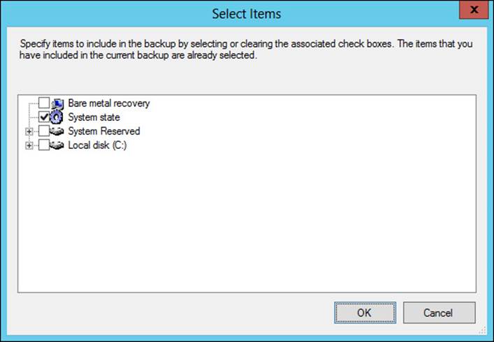
FIGURE 2-32 Backing up system state as part of a backup strategy
System state plays an important role in domain controller operation. You can restore system state with the command wbadmin start systemstaterecovery.
More Info: Domain Controller Recovery
See http://technet.microsoft.com/library/cc732238 for scenario overviews for backing up and recovering Active Directory Domain Services.
Restoring an Active Directory object and container using authoritative restore and the Recycle Bin
The Active Directory Recycle Bin keeps track of objects that have been removed from Active Directory. With the Active Directory Recycle Bin, objects are logically deleted and moved to the Deleted Objects container. Objects in the Deleted Objects container are eventually migrated to being recycled objects. Recycled objects eventually expire, after which the object is subject to garbage collection and removed entirely from the Active Directory database.
Performing an authoritative restore of an Active Directory container or object brings that container or object back to the state it was in prior to being deleted. Objects within domain directory partitions, application directory partitions, and configuration directory partitions can be restored. Active Directory objects are typically restored using the Active Directory Administrative Center (ADAC) but can also be restored using Windows PowerShell. The msDS-deletedObjectLifetime and tombstoneLifetime attributes determine the lifetime for the deleted object and the recycled object, respectively. By default, the value for these attributes are set to null, which in effect gives msDS-deletedObjectLifetime the same lifetime as tombstoneLifetime, or 180 days. Note that Active Directory objects can also be restored using the ldp.exe command, specifically by removing the isDeleted attribute from the CN=Deleted Objects container.
You can also restore Active Directory objects using Windows Server Backup, but doing so has several drawbacks over the Recycle Bin–based method discussed here. See http://technet.microsoft.com/en-us/library/dd379542 for more information.
Planning for and implementing backup and recovery using System Center Data Protection Manager (DPM)
System Center Data Protection Manager (DPM) provides a robust backup and recovery solution for SQL Server, Exchange Server, Hyper-V, and other products. DPM can also provide backup and recovery for standard file servers and Windows client computers. DPM is installed on its own servers and also uses a SQL Server instance, which can be installed locally or on a remote SQL server. DPM uses an agent on each protected computer. The agent can be installed using the Protection Agent Installation Wizard in the DPM console, as shown in Figure 2-33.
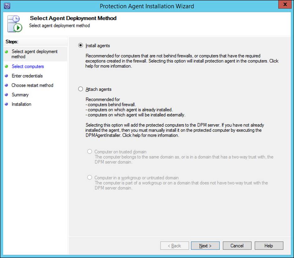
FIGURE 2-33 Installing a DPM agent
DPM uses a storage pool to manage the available space to which data sources are backed up. Both agent installation and storage pools are managed from within the Management workspace in the DPM administrator console. The storage pool must exist at the operating-system level, after which it can be added in the DPM console, as shown in Figure 2-34.
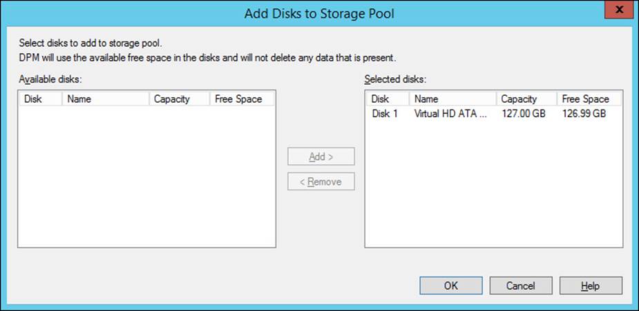
FIGURE 2-34 Adding disks to a DPM storage pool
Planning for a DPM deployment
Part of the planning for a DPM deployment is determining how many servers are necessary based on the existing infrastructure. You should consider network bandwidth between the DPM server and the servers or clients to be backed up. A minimum of 512 kilobytes (KB) is required for the connection. A DPM server can provide backup for up to 2,000 SQL Server databases or 3,000 client computers. The recommended disk space is 80 terabytes per DPM server for SQL Server and Exchange Server and 25 terabytes for SharePoint Server.
 Exam Tip
When planning snapshots, the limit is 9,000 snapshots per DPM server for express full backups and file recovery points. The limit does not apply to incremental synchronizations.
DPM needs to be used in an Active Directory environment but can provide backups across domains in the same forest and across forests as long as two-way trust exists between the domains or forests.
DPM uses the concept of protection groups to help organize data sources. Protection groups are nothing more than those data sources that share the same DPM configuration for backup. DPM provides a varying level of recovery for certain products. For example, different versions of Exchange Server can be protected at different levels by DPM. The article at http://technet.microsoft.com/en-us/library/jj627977.aspx provides an overview of protection groups and a table noting the protectable data for various sources.
In addition to the protectable data, Microsoft has created a deployment checklist, available at http://technet.microsoft.com/en-us/library/hh758205.aspx, which includes these overall steps:
![]() Identify each data source to be protected, including the type, size, fully qualified domain name, cluster name (if part of a cluster), and anything to be excluded from the backup.
Identify each data source to be protected, including the type, size, fully qualified domain name, cluster name (if part of a cluster), and anything to be excluded from the backup.
![]() Identify the protection method, such as short-term disk-based, long-term tape-based, and so on.
Identify the protection method, such as short-term disk-based, long-term tape-based, and so on.
![]() Determine the requirements around recovery in the event that a client being protected fails.
Determine the requirements around recovery in the event that a client being protected fails.
![]() Organize protection groups, decide whether to encrypt tapes, and determine the replica creation method.
Organize protection groups, decide whether to encrypt tapes, and determine the replica creation method.
Based on the requirements and information already determined, you can then calculate the amount of space needed to meet those requirements with DPM. This, along with the placement of servers, will lead you to determine the number of DPM servers necessary for your deployment.
Various firewall settings may need to be changed to support DPM on computers in untrusted domains. Specifically, support for DCOM on port 135 and WINSOCK on port 5718 for the agent coordinator and 5719 for the protection agent needs to be allowed on the computer to be protected. Additional considerations for non-domain joined computers can be found at http://technet.microsoft.com/library/hh757954.aspx.
Certificate-based authentication can also be used with DPM in both trusted and untrusted domains for the file server and Hyper-V data sources. See http://technet.microsoft.com/library/hh916530.aspx for more information.
Deploying DPM
Once the implementation has been planned, deploying DPM includes tasks such as installing the DPM server and any SQL Server instances to be used by DPM, installing protection agents, creating DPM storage pools, and creating protection groups.
Protection groups are created from within the Protection workspace in the DPM administrator console using the Create New Protection Group Wizard. Within the wizard, you first select whether to protect servers or clients, as shown in Figure 2-35.
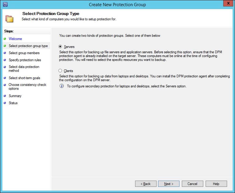
FIGURE 2-35 Selecting the type of resource to be protected
Next, the servers to be protected are selected, along with the data to be protected on each server, as shown in Figure 2-36.
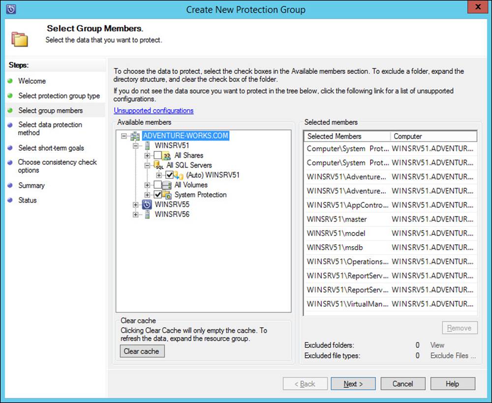
FIGURE 2-36 Selecting the data to be protected
The protection group name and mode are selected next, as shown in Figure 2-37.
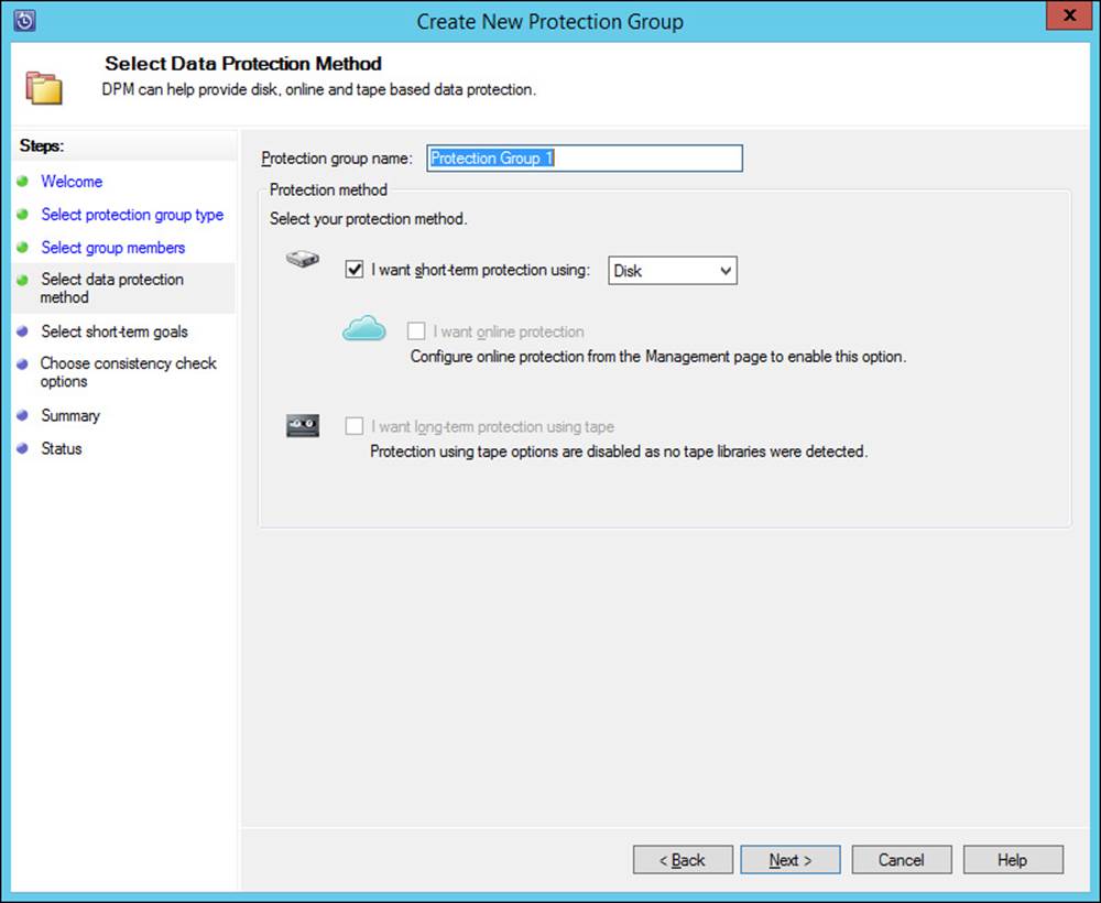
FIGURE 2-37 Setting parameters for the protection group
The protection schedule is set next, as shown in Figure 2-38.
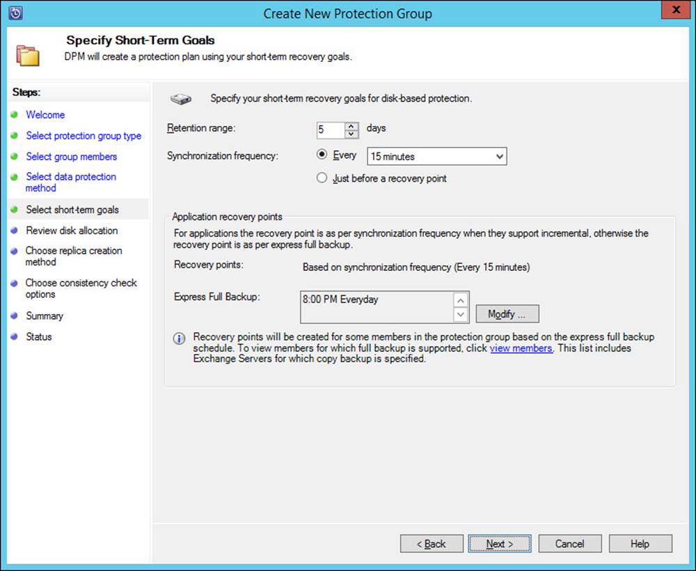
FIGURE 2-38 Configuring the protection schedule for a protection group
The disk allocation based on the initial calculation of data size is shown next, enabling you to make changes to the location and settings related to protection. This is illustrated in Figure 2-39.
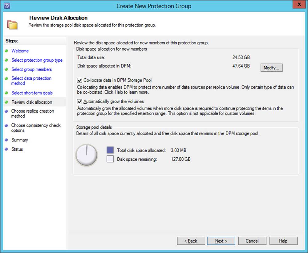
FIGURE 2-39 Reviewing disk allocation for a protection group
The replica creation method is set next in the wizard, as shown in Figure 2-40.
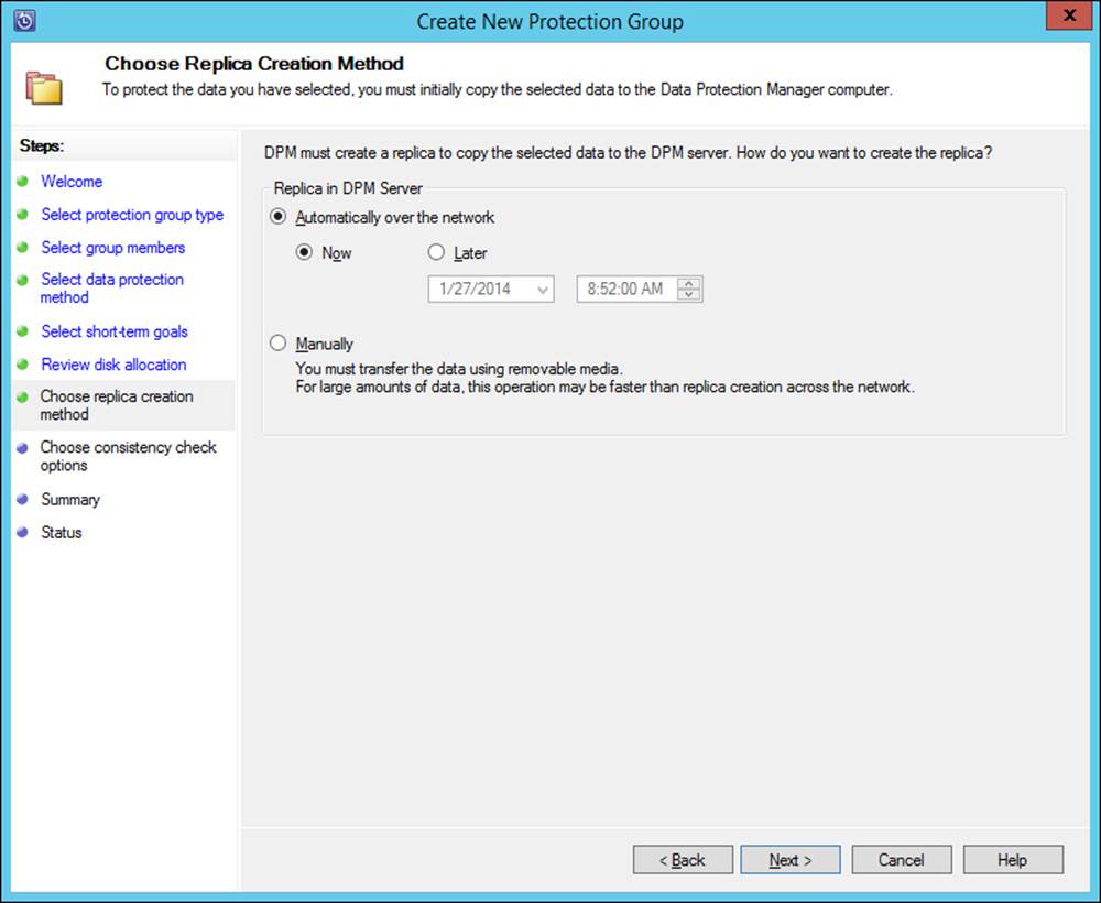
FIGURE 2-40 Choosing a replica method for a protection group
Finally, the consistency check options are set for the protection group, as shown in Figure 2-41.
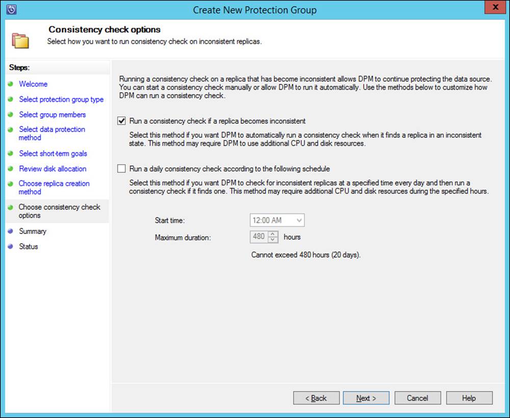
FIGURE 2-41 Choosing consistency check options for a protection group
More Info: Deploying DPM
See http://technet.microsoft.com/en-us/library/hh757840.aspx for specific information on protecting various types of servers and clients with DPM.
Thought experiment: Planning a backup strategy
In the following thought experiment, apply what you’ve learned about this objective to predict what steps you need to take. You can find answers to these questions in the “Answers” section at the end of this chapter.
You’re planning a backup strategy for an organization. The organization consists of eight Windows Server 2012 servers along with shared storage on an NAS device. The network runs Active Directory Domain Services along with standard file shares, DHCP, DNS, and so on. The NAS device is automatically backed up to the cloud and is outside of the scope of your engagement. Your task is to plan for backup of the Windows Server 2012 servers.
Discuss the overall considerations for backup of the servers and any other items that you can recommend to help ensure availability in the event of a server outage or a site-wide disaster.
Objective summary
![]() Backup and recovery strategies center around ensuring business continuity in the event of disaster.
Backup and recovery strategies center around ensuring business continuity in the event of disaster.
![]() Windows Server Backup can be used to create a backup of Windows servers and can back up system state, which is important for Active Directory.
Windows Server Backup can be used to create a backup of Windows servers and can back up system state, which is important for Active Directory.
![]() The Active Directory Recycle Bin provides an easy way to recover objects that have been deleted from Active Directory.
The Active Directory Recycle Bin provides an easy way to recover objects that have been deleted from Active Directory.
![]() DPM can be used to provide backup and recovery for various services and server types.
DPM can be used to provide backup and recovery for various services and server types.
![]() DPM can protect computers joined to the domain and those outside of the domain.
DPM can protect computers joined to the domain and those outside of the domain.
Objective review
Answer the following questions to test your knowledge of the information in this objective. You can find the answers to these questions and explanations of why each answer choice is correct or incorrect in the “Answers” section at the end of this chapter.
1. Which item should be included in a backup for Active Directory?
A. System state
B. AD DS
C. Service Master
D. FSMO
2. Which property defines the lifetime of a deleted object in the Active Directory Recycle Bin?
A. tombstoneState
B. tombstoneLife
C. msDS-deletedObjectLifetime
D. msDS-recycleBinLifeTime
3. Which portions of an Active Directory implementation should be kept on a separate volume?
A. SYSVOL
B. Active Directory database
C. ENTVOL
D. Recycle Bin
Answers
This section contains the solutions to the thought experiments and answers to the lesson review questions in this chapter.
Objective 2.1: Thought experiment
Ideally, you would have an odd number of votes in the Quorum configuration. Therefore, you can configure a witness so that it also has a vote. Because the servers are located in different data centers, it’s likely that you’ll use a file-share witness. The Configure Cluster Quorum Wizard is used to reconfigure Quorum settings and is found in the More Actions area of a cluster’s shortcut menu.
Objective 2.1: Review
1. Correct answer: B
A. Incorrect: Get-ClusterInfo is not a real cmdlet.
B. Correct: Get-ClusterResouce | Get-ClusterParameter shows current IP and networking information.
C. Incorrect: ifconfig /cluster is not a valid command.
D. Incorrect: Get-ClusterNetworkInfo is not a valid command.
2. Correct answer: C
A. Incorrect: Node Majority (Witness Voting) is not a valid Quorum type.
B. Incorrect: Node Majority (Disk Witness) is not a valid Quorum type.
C. Correct: No Majority (Disk Witness Only) allows only the witness to have a vote.
D. Incorrect: No Majority (Witness Vote Only) is not a valid Quorum type.
3. Correct answer: C
A. Incorrect: Long-term node or witness failure is a valid reason for changing Quorum configuration.
B. Incorrect: Adding or removing node failure is a valid reason for changing Quorum configuration.
C. Correct: Temporary failure of a network switch is not a valid reason for changing Quorum settings.
D. Incorrect: Multi-site cluster recovery failure is a valid reason for changing Quorum configuration.
Objective 2.2: Thought experiment
For this experiment, you’ll most likely need to use multicast because each of the servers has only one adapter. Multicast enables the servers to still communicate with each other if necessary. It’s likely that the default setting, Single affinity, will be appropriate for the port rule for the web application, because this will keep the client served by the same server as long as the client IP address remains the same for a given session.
Objective 2.2: Review
1. Correct answers: A, D
A. Correct: Single affinity provides state management.
B. Incorrect: None is not a valid option.
C. Incorrect: Session is not a valid option.
D. Correct: Network affinity provides state management.
2. Correct answer: B
A. Incorrect: Single is not a valid operating mode.
B. Correct: Unicast is used when there’s more than one adapter and the hosts need to communicate with each other.
C. Correct: Multicast can be used when there’s more than one adapter but is typically used when there’s only one adapter.
D. Incorrect: Anycast is not a valid operating mode.
3. Correct answer: A
A. Correct: Single Host distributes traffic to a single host based on priority.
B. Incorrect: Multiple Hosts distributes traffic across hosts.
C. Incorrect: Failover is not a valid filter mode.
D. Incorrect: Round-Robin is not a valid filter mode.
Objective 2.3: Thought experiment
You can create a domain-based namespace for this solution because the organization uses AD DS. The Optimize For Scalability option should be used because there are domain controllers at each location that the clients can use to get namespace information.
For replication, hub and spoke can be used if the main place for information is the central location; otherwise, full mesh can be used. You should also configure referrals so that there’s a priority for local site. Optionally, you can configure referral traffic to only use servers at the local site.
You can configure replication traffic and its accompanying bandwidth usage according to a schedule that makes sense for the client. For example, if it’s acceptable for there to be a delay in changes being replicated, you can disable replication during business hours or limit the bandwidth usage during that time.
Objective 2.3: Review
1. Correct answer: B
A. Incorrect: Simple resiliency requires only one disk.
B. Correct: Parity resiliency requires at least three disks.
C. Incorrect: Mirror resiliency requires at least two disks.
D. Incorrect: Level 5 is not a virtual disk resiliency type.
2. Correct answer: C
A. Incorrect: Set-MPIOSetting -LoadBalancePolicy Failover is not an available command.
B. Incorrect: There is not an All option to the Set-MSDSMGlobalDefaultLoadBalance -Policy command.
C. Correct: Set-MSDSMGlobalDefaultLoadBalancePolicy -Policy FOO sets the policy to failover only.
D. Incorrect: Set-MPIOSetting -Policy None is not a valid command.
3. Correct answer: A
A. Correct: Full mesh can be used with two servers.
B. Incorrect: Hub and spoke requires at least three servers.
C. Incorrect: Wheel is not an available option.
D. Incorrect: Dual-mesh is not an available option.
Objective 2.4: Thought experiment
There are three basic options for DHCP failover: native DHCP failover in the DHCP service, failover clustering, and split scope. Split scope is limited because it doesn’t provide a true failover, but only a temporary solution in the event that the primary server fails, requiring manual intervention to remediate failure. A failover cluster won’t work for this client because they use NAS and local storage. The native DHCP failover is recommended for this scenario because it provides redundancy while requiring little management or intervention.
Objective 2.4: Review
1. Correct answer: A
A. Correct: Standby is active/passive with a secondary server taking over if needed.
B. Incorrect: Load Balance is active/active.
C. Incorrect: Passive Partner is not a valid type.
D. Incorrect: Split Address is not a valid type.
2. Correct answer: A
A. Correct: SMB is supported by both scale-out and generic file server clustering.
B. Incorrect: BranchCache is not supported by scale-out file server.
C. Incorrect: Data Deduplication is not supported by scale-out file server.
D. Incorrect: File Classification Infrastructure is not supported by scale-out file server.
3. Correct answers: A, C
A. Correct: Generic Application can replicate registry settings.
B. Incorrect: Generic Script doesn’t include registry replication.
C. Correct: Generic Service can replicate registry settings.
D. Incorrect: Generic Registry replication doesn’t exist.
Objective 2.5: Thought experiment
Overall considerations include the amount of traffic available and what to back up. Because the organization already backs up to the cloud, you may be able to use a cloud-based remote solution for Windows backup. You should ensure that system state is backed up. You should ensure that the day-to-day issues, such as adequate domain controllers, exist as well. Adding the Active Directory Recycle Bin can also help alleviate issues surrounding inadvertent deletion of AD DS objects.
Objective 2.5: Review
1. Correct answer: A
A. Correct: System state should be included in a backup strategy for Active Directory.
B. Incorrect: AD DS is not an available option.
C. Incorrect: Service Master is not a valid role.
D. Incorrect: FSMO is not related to backup.
2. Correct answer: C
A. Incorrect: tombstoneState is not a valid property for this question.
B. Incorrect: tombstoneLife is not a valid property (though tombstoneLifetime is, and it defines the lifetime for recycled objects).
C. Correct: msDS-deletedObjectLifetime defines the lifetime for a deleted object.
D. Incorrect: msDS-recycleBinLifeTime is not a real property.
3. Correct answers: A, B
A. Correct: SYSVOL should be kept on a separate volume.
B. Correct: Active Directory database should be kept on a separate volume.
C. Incorrect: ENTVOL is not part of an Active Directory implementation.
D. Incorrect: Recycle Bin is not kept on a separate volume
All materials on the site are licensed Creative Commons Attribution-Sharealike 3.0 Unported CC BY-SA 3.0 & GNU Free Documentation License (GFDL)
If you are the copyright holder of any material contained on our site and intend to remove it, please contact our site administrator for approval.
© 2016-2026 All site design rights belong to S.Y.A.