Microsoft System Center: Network Virtualization and Cloud Computing (2014)
CHAPTER 1
Hyper-V Network Virtualization internals
Network virtualization in general and Hyper-V Network Virtualization specifically are relatively new concepts. Unlike server virtualization, which is a mature technology that is widely understood, network virtualization lacks this same broad understanding. The first section of this chapter walks through key concepts in Hyper-V Network Virtualization and the benefits it provides. The later section of this chapter covers how to set up a basic virtual network and connects the key concepts to the implementation.
Overview
Server virtualization is a well-known concept by which many virtual servers can run on a single physical server with the appearance of running on a dedicated physical server. Typically, a hypervisor provides an abstraction of physical resources (CPU, memory, storage, and local networking) allowing for this illusion. The benefits of server virtualization are also well known and, among others, include:
![]() Isolation (performance and security) between virtual servers
Isolation (performance and security) between virtual servers
![]() More efficient use of physical resources
More efficient use of physical resources
![]() Easier movement of workloads across physical servers
Easier movement of workloads across physical servers
Network virtualization, from a high level, has the same goals when it comes to the network fabric that connects virtual servers. Network virtualization should allow a virtual network, including all of its IP addresses, routes, network appliances, and so on, to appear to be running directly on the physical network. This allows the servers connected to that virtual network to continue to operate as if they were running directly on the physical network even as multiple virtual networks share the physical network. This concept of virtual networks allows the network to gain many of the same benefits that server virtualization provided to servers. Figure 1-1 shows conceptually how network virtualization and server virtualization are the same.
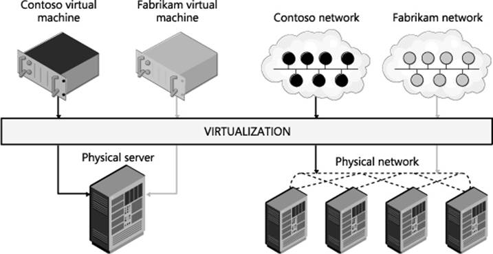
FIGURE 1-1 Network virtualization is conceptually the same as server virtualization.
In many ways, without network virtualization, the full range of benefits of server virtualization cannot be realized. Consider for example a virtualized SQL server, made possible by great strides in virtualizing high performance workloads. A virtualized SQL server should provide all the benefits of server virtualization, such as VM migration, but a physical network reduces the flexibility you actually get. This SQL server is assigned an IP address, which means that it has to stay in that IP address physical subnet. This limits any migration to only hosts that are attached to the same physical subnet (maybe only a rack or two out of a whole data center). Also, if the SQL server is on a VLAN, you must make sure that the VLAN has been properly configured across the physical network. With network virtualization you can decouple the network that the SQL server is attached to from the physical network and take full advantage of the potential of server virtualization. So without network virtualization, a key feature of server virtualization is much less flexible (i.e., you can move VMs only to hosts on the same physical subnet) and less automated (i.e., you might need to reconfigure the network before a VM can be migrated). This is just one such example of how network virtualization can allow you to gain the full potential of server virtualization.
Before diving into the details of how Hyper-V Network Virtualization works, consider the following summary of a few key benefits of network virtualization that help solve major problems you may face:
![]() The ability to run multiple virtual networks securely isolated from each other all with the illusion that they are each alone on the physical network.
The ability to run multiple virtual networks securely isolated from each other all with the illusion that they are each alone on the physical network.
![]() The ability to move VMs around in the physical network without having to reconfigure the physical network, including the IP address and VLANs.
The ability to move VMs around in the physical network without having to reconfigure the physical network, including the IP address and VLANs.
![]() The ability to abstract the virtual network away from the underlying physical network.
The ability to abstract the virtual network away from the underlying physical network.
Network virtualization provides value to three main groups: enterprises, workload owners, and service providers.
For enterprises, the biggest benefit of network virtualization is the ability to consolidate resources using a private cloud. For several years, enterprises have been implementing server virtualization to help consolidate workloads, but this approach has limitations. This is especially true when workloads expect a specific network topology, one that the private cloud’s physical network can’t accommodate. For enterprises that have grown through acquisitions and mergers, this can potentially be a major issue since each acquisition will have an existing IT infrastructure including network topologies that might have been in place for years. Network virtualization allows these existing network topologies to be decoupled from the underlying physical infrastructure so that even overlapping IP addresses can easily run on the same infrastructure. Also, enterprises can leverage the hybrid IT model where they only partially move their workloads to the cloud. Network virtualization helps reduce the pain of partially migrating resources to the cloud because the virtual network is not tied to the physical network.
For workload owners (whether on-premises, in a hosted environment, or in the cloud), the big benefit is that they do not have to change the configuration of the workload regardless of whether the workload needs to be moved around. Line of business applications in particular are sometimes designed to run with a particular network configuration, even with some components having well-defined IP addresses. As a result, to move an application to the cloud or to a service provider, a workload owner must either change the configuration of the application or figure out how the service provider can allow policies, VM settings, and IP addresses to be preserved. With network virtualization, this is no longer an issue because the workload owner can now move an application into the cloud while preserving all network settings, including IP addresses, even if they overlap with those belonging to another customer in the cloud or at the service provider.
For service providers, network virtualization provides some clear benefits. Most importantly, it allows them to offer their customers the ability to bring their own networks including any network settings (such as IP addresses, network topologies, and network services) that the customer wants to preserve. Network virtualization thus gives service providers a scalable, multi-tenant solution that provides them with flexibility concerning where they place workloads. For large service providers this is particularly important as they can now utilize their resources more efficiently and not have their resources usage dictated by customer requirements.
Network virtualization in some form has already been happening for some time, most prominently using VLANs. Virtualization using VLANs has recently run into issues, however, such as:
![]() Scalability Limit of 4,095 VLANs and specific switches and routers support only 1,000 VLANs.
Scalability Limit of 4,095 VLANs and specific switches and routers support only 1,000 VLANs.
![]() Size VLANs are limited to a single L2 network. This means that an individual L2 network must be very large (which has its own challenges) for a large number of VMs to participate in a specific VLAN. This is becoming even more of an issue because current data center trends are moving to smaller L2 domains (typically a rack or less).
Size VLANs are limited to a single L2 network. This means that an individual L2 network must be very large (which has its own challenges) for a large number of VMs to participate in a specific VLAN. This is becoming even more of an issue because current data center trends are moving to smaller L2 domains (typically a rack or less).
![]() Deployment Often when VMs are migrated, the configuration of many switches and routers must be updated. In addition, VLAN configuration has to be coordinated with the Hyper-V hosts because the virtual switch must have matching VLAN configuration. Finally, where VMs can migrate is limited because they must stay in the same physical L2 domain to retain their existing IP address.
Deployment Often when VMs are migrated, the configuration of many switches and routers must be updated. In addition, VLAN configuration has to be coordinated with the Hyper-V hosts because the virtual switch must have matching VLAN configuration. Finally, where VMs can migrate is limited because they must stay in the same physical L2 domain to retain their existing IP address.
Due to these challenges, the industry has been moving to different models of virtual networks, including OpenFlow-based virtual networks and overlay networks. IBM, NEC, and Big Switch have commercially available OpenFlow-based virtual network solutions. Cisco’s VXLAN based Network Virtualization, VMWare NSX Network Virtualization, and Microsoft’s Hyper-V Network Virtualization are examples of the overlay network–based solution for network virtualization. The rest of this chapter will detail how Hyper-V Network Virtualization works.
Architecture and key concepts
Hyper-V Network Virtualization (HNV) provides a complete end-to-end solution for network virtualization that uses a network overlay technology paired with a control plane and gateway to complete the solution. These three pieces are embodied in the following:
![]() The Hyper-V virtual switch (with a virtual network adapter attached to a virtual network)
The Hyper-V virtual switch (with a virtual network adapter attached to a virtual network)
![]() Microsoft System Center 2012 Virtual Machine Manager (VMM) as the control plane
Microsoft System Center 2012 Virtual Machine Manager (VMM) as the control plane
![]() The in-box HNV Gateway in Windows Server 2012 R2
The in-box HNV Gateway in Windows Server 2012 R2
At the core of HNV is a network overlay technology that allows separation between the virtual network and the underlying physical network. Network overlays are a well-known technique for layering a new network on top of an existing network. This is often done using a network tunnel. Typically, this tunnel is provided by packet encapsulation, essentially putting the packet for the virtual network inside a packet that the physical infrastructure can route (see Figure 1-2).
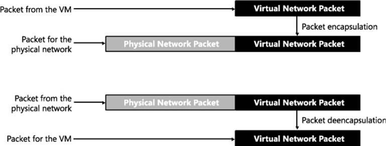
FIGURE 1-2 Network tunnel through packet encapsulation/de-encapsulation.
Network overlays are widely used for a number of scenarios, including VPN connections over wide area network (WAN) connections and Multiprotocol Label Switching (MPLS) connections over a variety of telecommunication networks. The endpoints in the overlay network have the intelligence needed to begin or terminate the tunnel by either encapsulating or de-encapsulating the packet. As mentioned earlier, the implementation of the overlay network is done as part of the Hyper-V virtual switch through the HNV filter, which encapsulates and de-encapsulates the packets as they are entering and exiting the virtual machines. This is discussed in detail in the “HNV architecture in the Hyper-V virtual switch” section.
In addition to an overlay network, HNV also provides a control plane that manages the overlay network independently from the physical network. There are two main types of control planes, centralized and distributed, each with its own strengths. For HNV, a centralized control plane is used to distribute policies to the endpoints needed to properly encapsulate and de-encapsulate the packets. This allows for a centralized policy with a global view of the virtual network while the actual encapsulation and de-encapsulation based on this policy happens at each end host. This makes for a very scalable solution since the policy updates are relatively infrequent while the actual encapsulation and de-encapsulation is very frequent (every packet). Windows provides PowerShell APIs to program the policies down to the Hyper-V virtual switch, which means anyone can build the central policy store. System Center 2012 Virtual Machine Manager implements the necessary functionality to be the central policy store and is the recommended solution, especially when System Center VMM is managing your virtual machines. (This text assumes that VMM is being used as the centralized policy store for HNV.)
Finally, because a virtual network that cannot communicate with the outside world is of little value, gateways are required to bridge the virtual network and either the physical network or other virtual networks. Windows Server 2012 R2 provides an in-box gateway and several third parties, including F5, Iron Networks, and Huawei, have gateways that can provide the bridge needed for virtual networks.
Figure 1-3 shows how the three pieces (VMM, the HNV Gateway, and the Hyper-V virtual switch) combine to provide a complete network virtualization solution. In this example the inbox Windows HNV Gateway provides VPN capabilities to connect customers over the Internet to data center resources being hosted at a service provider.
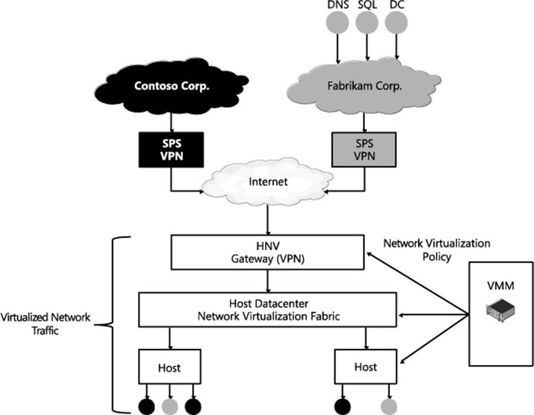
FIGURE 1-3 The Microsoft network virtualization solution.
Virtual machine network
The virtual machine network is a core concept in network virtualization. Much like a virtual server is a representation of a physical server including physical resources and operating system services, a virtual network is a representation of a physical network including IP, routing policies, and so on. Just like a physical network forms an isolation boundary where there needs to be explicit access to go outside the physical network, the virtual machine network also forms an isolation boundary for the virtual network.
In addition to being an isolation boundary, a VM network has most of the characteristics of a physical network, but several features are unique to VM networks:
![]() First, there can be many VM networks on a single physical network. This a major advantage for virtual networks, particularly in data centers that contain multiple tenants, such as what a service provider or cloud provider might have. These VM networks are isolated from each other even though their traffic is flowing across the same physical network and even in the same hosts. Specifically, the Hyper-V virtual switch is responsible for this isolation.
First, there can be many VM networks on a single physical network. This a major advantage for virtual networks, particularly in data centers that contain multiple tenants, such as what a service provider or cloud provider might have. These VM networks are isolated from each other even though their traffic is flowing across the same physical network and even in the same hosts. Specifically, the Hyper-V virtual switch is responsible for this isolation.
![]() Second, it is good to understand how IP and MAC addresses work in VM networks. There are two important cases. Within a single VM network, IP and MAC addresses cannot overlap, just like in a physical network. On the other hand, across multiple VM networks, each VM network can contain the same IP and MAC address, even when those VM networks are on the same physical network. Also, HNV supports both IPv4 and IPv6 addresses. Currently, HNV does not support a mixture of IPv4 and IPv6 customer addresses in a particular VM network. Each VM network must be configured to use either IPv6 or IPv4 for the customer addresses. On a single host there can be a mixture of IPv4 and IPv6 customer addresses if they are in different VM networks.
Second, it is good to understand how IP and MAC addresses work in VM networks. There are two important cases. Within a single VM network, IP and MAC addresses cannot overlap, just like in a physical network. On the other hand, across multiple VM networks, each VM network can contain the same IP and MAC address, even when those VM networks are on the same physical network. Also, HNV supports both IPv4 and IPv6 addresses. Currently, HNV does not support a mixture of IPv4 and IPv6 customer addresses in a particular VM network. Each VM network must be configured to use either IPv6 or IPv4 for the customer addresses. On a single host there can be a mixture of IPv4 and IPv6 customer addresses if they are in different VM networks.
![]() Third, only VMs can be joined to a virtual network. Windows does allow the host operating system to run through the Hyper-V virtual switch and can be attached to a VM network but VMM, in System Center 2012 R2, won’t configure the host operating system to be attached to a virtual network.
Third, only VMs can be joined to a virtual network. Windows does allow the host operating system to run through the Hyper-V virtual switch and can be attached to a VM network but VMM, in System Center 2012 R2, won’t configure the host operating system to be attached to a virtual network.
![]() Fourth, currently a single instance of VMM manages a particular VM network. This limits the size of the VM network to the number of VMs supported by a single instance of VMM. In the R2 release, VMM allows a maximum of 8,000 VMs and 4,000 VM networks.
Fourth, currently a single instance of VMM manages a particular VM network. This limits the size of the VM network to the number of VMs supported by a single instance of VMM. In the R2 release, VMM allows a maximum of 8,000 VMs and 4,000 VM networks.
In VMM, the virtual machine network is called “VM network” and has a workflow that allows for the creation and deletion of VM networks and management of the properties associated with a VM network. In the HNV Windows PowerShell APIs, the VM network is identified by a Routing Domain ID (RDID) property. This RDID property must be unique within the physical network and set automatically by VMM.
Virtual subnet
Within a VM network, there must be at least one virtual subnet. The concept of a virtual subnet is identical to a subnet in a physical network in that it provides a broadcast domain and is a single LAN segment. In HNV, the virtual subnet is encoded in each virtualized packet in the Virtual Subnet ID (VSID) property and is a 24-bit field discoverable on the wire. Because of the close approximation to VLANs, valid VSIDs range from 4096 to 16,777,215 beginning after the valid VLAN range. The Virtual Subnet ID must also be unique within a particular physical network, typically defined as the network being managed by VMM.
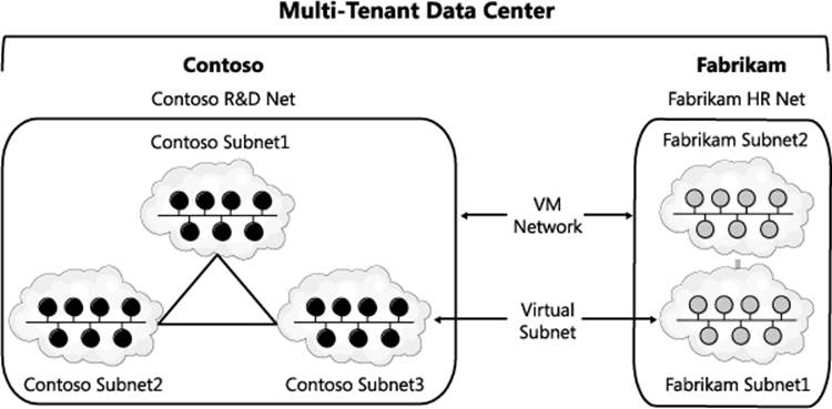
FIGURE 1-4 Example of how VM networks and virtual subnets are related.
To understand how VM networks and virtual subnets relate to each other, Figure 1-4 shows an example of multi-tenant data center network virtualization turned on. In this example, there are two tenants representing different companies, potentially competitors. They want their traffic to be securely isolated from each other so they form two VM networks. Inside each of these VM networks they are free to create one or more virtual subnets and attach VMs to particular subnets, creating the particular network topology that suits their needs.
VM network routing
After VM networks and virtual subnets, the next concept to understand is how routing is handled in VM networks, specifically, routing between virtual subnets and routing beyond the VM network. For more detail on how routing works and the packet flow related to routing in a VM network, see the section titled "Packet flows."
ROUTING BETWEEN VIRTUAL SUBNETS
In a physical network, a subnet is the L2 domain where machines (virtual and physical) can directly communicate with each other without having to be routed. In Windows Server, if you statically configure a network adapter, you must set a default gateway, which is the IP address to send all traffic that is going out of the particular subnet so that it can be routed appropriately. This is typically the router for the physical network. HNV uses a built-in router that is part of every host to form a distributed router for the virtual network. This means that every host, in particular the Hyper-V virtual switch, acts as the default gateway for all traffic that is going between virtual subnets that are part of the same VM network. In Windows Server 2012 and Windows Server 2012 R2, the address used as the default gateway is the “.1” address for the subnet. This .1 address is reserved in each virtual subnet for the default gateway and cannot be used by VMs in the virtual subnet.
HNV acting as a distributed router allows for a very efficient way for all traffic inside a VM network to be routed appropriately because each host can directly route the traffic to the appropriate host without needing an intermediary. This is particularly true when two VMs in the same VM network but different virtual subnets are on the same physical host. As you will see later in this section, when the packet flows are described with the distributed router the packet never has to leave the particular host.
ROUTING BEYOND A VM NETWORK
Sometimes a packet needs to go beyond the VM network. As explained earlier, the VM network is an isolation boundary, but that does not mean that no traffic should go outside of the VM network. In fact, you could easily argue that if there was no way to communicate outside the VM network then network virtualization wouldn’t be of much use. So much like physical networks have a network edge that controls what traffic can come in and out, virtual networks also have a network edge in the form of an HNV gateway. The role of the HNV Gateway is to provide a bridge between a particular VM network and either the physical network or other VM networks.
An HNV gateway has several different capabilities, including:
![]() Forwarding Forwarding is the most basic function of the gateway and simply encapsulates or de-encapsulates packets between the VM network and the physical network the forwarding gateway is bridging to. This means that the IP address in the VM network must be routable on the physical network. This type of gateway would typically be used from a VM in a VM network to a shared resource like storage or a backup service that is on the physical network. Forwarding can also be used to connect a VM network to the edge of the physical network so that the VM network can use the same edge services (firewall, intrusion detection) as the physical network.
Forwarding Forwarding is the most basic function of the gateway and simply encapsulates or de-encapsulates packets between the VM network and the physical network the forwarding gateway is bridging to. This means that the IP address in the VM network must be routable on the physical network. This type of gateway would typically be used from a VM in a VM network to a shared resource like storage or a backup service that is on the physical network. Forwarding can also be used to connect a VM network to the edge of the physical network so that the VM network can use the same edge services (firewall, intrusion detection) as the physical network.
![]() VPN There are two types of VPNs:
VPN There are two types of VPNs:
• Site-to-Site The Site-To-Site function of the gateway allows direct bridging between a VM network and a network (physical or another VM network) in a different data center. This is typically used in hybrid scenarios where a part of a tenant’s data center’s network is on-premises and part of the tenant’s network is hosted virtually in the cloud. To use the Site-To-Site function, the VM network must be routable in the network at the other site and the other site’s network must be routable in the VM network. Also, there must be a site-to-site gateway on each side of the connection (for example, one gateway on-premises in the enterprise and one gateway at the service provider).
• Remote Access (Point-to-Site) The Remote Access function of the gateway allows a user on a single computer to bridge in the virtual network. This is similar to the Site-To-Site function but doesn’t require a gateway on each side, only on one side. For example, with Remote Access an administrator can use a laptop to connect to the virtual network from the corporate network instead of an on-premises data center network.
![]() NAT/Load Balancing The final function that the gateway can provide is NAT/Load Balancing. As expected, NAT/Load Balancing allows connectivity to an external network like the Internet without having the internal virtual subnets and IP addresses of the VM network routable external to the VM network. The NAT capability allows for a single externally routable IP address for all connections external to the VM network or can provide a one-to-one mapping of a VM that needs to be accessed from the outside where the address internal to the virtual network is mapped to an address that is accessible from the physical network. Load Balancer provides the standard load balancing capabilities with the primary difference being that the virtual IP (VIP) is on the physical network while the dedicated IPs (DIPs) are in the VM network.
NAT/Load Balancing The final function that the gateway can provide is NAT/Load Balancing. As expected, NAT/Load Balancing allows connectivity to an external network like the Internet without having the internal virtual subnets and IP addresses of the VM network routable external to the VM network. The NAT capability allows for a single externally routable IP address for all connections external to the VM network or can provide a one-to-one mapping of a VM that needs to be accessed from the outside where the address internal to the virtual network is mapped to an address that is accessible from the physical network. Load Balancer provides the standard load balancing capabilities with the primary difference being that the virtual IP (VIP) is on the physical network while the dedicated IPs (DIPs) are in the VM network.
In Windows Server 2012 R2 the in-box gateway provides Forwarding, Site-to-Site, and NAT functionality. The gateway is designed to be run in a virtual machine and takes advantage of the host and guest clustering capabilities in Windows and Hyper-V to be highly available. A second major feature of the gateway is that a single gateway VM can be the gateway for multiple VM networks. This is enabled by the Windows networking stack becoming multi-tenant aware with the ability to compartmentalize multiple routing domains from each other. This allows multiple VM networks to terminate in the same gateway even if there are overlapping IP addresses.
In addition to the in-box HNV Gateway, there are a growing number of third-party gateways that provide one or more of these functions. These gateways integrate with VMM just as the in-box HNV Gateway does and acts as the bridge between the VM network and the physical network.
A few other requirements of VMM support of gateways should be noted:
![]() There can be only one gateway IP address per VM network.
There can be only one gateway IP address per VM network.
![]() The gateway must be in its own virtual subnet.
The gateway must be in its own virtual subnet.
![]() There can be multiple gateway VMs on the same host, but there cannot be other VMs on a VM network on the same host as the gateway VMs.
There can be multiple gateway VMs on the same host, but there cannot be other VMs on a VM network on the same host as the gateway VMs.
Packet encapsulation
Packet encapsulation is the core of network virtualization. In particular, in overlay networking technologies like HNV, packet encapsulation is the way in which the virtual network is separated from the physical network. Basically, in packet encapsulation, the packet for the virtual network is put inside (encapsulated) a packet that is understood by the physical network. Before the packet is delivered to the VM, the packet that is understood by the physical network is stripped off (de-encapsulated), leaving only the packet for virtual network. As mentioned previously, in HNV the VM switch provides the packet encapsulation functionality.
There are many different encapsulation formats, including recent ones like Virtual eXtensible Local Area Network (VXLAN), Stateless Transport Tunneling Protocol for Network Virtualization (STT), and Generic Routing Encapsulation (GRE). HNV uses a particular format of GRE, called Network Virtualization using Generic Routing Encapsulation (NVGRE), for the encapsulation protocol. GRE was chosen as the encapsulation protocol for HNV because it is an industry standard mechanism for packet encapsulation protocol. NVGRE is a specific format of GRE that is provided jointly by Microsoft, Arista, Intel, Dell, HP, Broadcom, Emulex, and Mellanox as an Internet draft at the IETF. A full version of the specification can be found at http://tools.ietf.org/html/draft-sridharan-virtualization-nvgre-00.
The NVGRE wire format has an outer header with source and destination MAC and IP addresses and an inner header with source and destination MAC and IP addresses. In addition there is the standard GRE header between the outer and inner headers. In the GRE header, the Key field is a 24-bit field where the virtual subnet ID (VSID) is put in the packet. As mentioned previously, this allows the VSID to be explicitly set in each packet going across the virtual network. To get hands on with the NVGRE packet format you can set up a simple HNV network (see the section titled "Hyper-V Network Virtualization: Simple setup") and use Message Analyzer to decode the packets and see NVGRE packets on the wire.
Customer Address (CA)
When looking at the NVGRE format it is important to understand where the address space for the inner packet comes from. It is called the Customer Address (CA). The CA is the IP address of a network adapter that is attached to the VM network. This address is only routable in the VM network and does not necessarily route anywhere else. In VMM, this CA comes from the IP pool assigned to a particular virtual subnet in a VM network.
Provider Address (PA)
The outer packet is similar in that the IP address is called the Provider Address (PA). The PA must be routable on the physical network but should not be the IP address of the physical network adapter or a network team. In VMM, the PA comes from the IP pool of the logical network.
Figure 1-5 shows how NVGRE, CAs, and PAs relate to each other and the VMs on the VM networks.
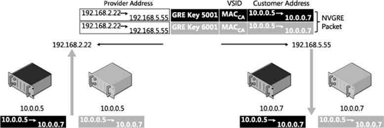
FIGURE 1-5 NVRGE, CA, and PA.
Hyper-V virtual switch
The Hyper-V virtual switch is the component that provides the network virtualization features on the end hosts. Specifically it provides all the capabilities pertaining to NVGRE encapsulation/de-encapsulation, policy enforcement (i.e., ensuring VMs on different VM networks can’t communicate with each other), routing of packets between virtual subnets in the same VM network, and managing the local host’s network virtualization policy as configured by VMM.
A design change between Windows Server 2012 and Windows Server 2012 R2 allows more compatibility between HNV and Hyper-V virtual switch extensions. In Windows Server 2012, HNV was an NDIS LWF, which meant that Hyper-V virtual switch extensions worked only on the customer address space. This also meant that capture and filter extensions were not aware of the underlying physical networking being used for HNV packets and that forwarding switch extensions could not co-exist with HNV, so customers had to choose a forwarding switch using HNV or a particular forwarding extension. Windows Server 2012 R2 introduced the ability for switch extensions to work on both the original customer address packet and the encapsulated provider address packet (see Figure 1-6). In addition, forwarding switch extensions can co-exist with HNV, allowing multiple network virtualization solutions (one provided by HNV and another provided by the forwarding switch extension) to co-exist on the same Hyper-V host.
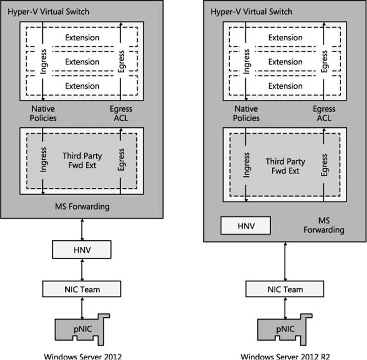
FIGURE 1-6 HNV architectural update in Windows Server 2012 R2.
Improved interoperability with switch extensions was the primary reason for the change, but a nice side effect is that the HNV NDIS LWF does not have to be bound to network adapters anymore. After you attach a network adapter to the virtual switch you can enable HNV simply by assigning a virtual subnet ID to a particular virtual network adapter. For those using VMM to manage VM networks this is transparent, but for anyone using PowerShell this will save an often-missed step.
Control plane
The control plane is comprised of two major pieces: HNV policy records and the central policy store. The control plane can be characterized from a high level as a centralized control plane that uses policy records to drive a distributed router on each host.
Policy records
Policy records drive the distributed router running on each host. The best way to understand the policy records is to go through the PowerShell APIs used to set the policy records. There are four APIs to look at. Each API has a New, Get, Set, and Remove command, but for this review, the New command is most interesting.
New-NetVirtualizationCustomerRoute
The New-NetVirtualizationCustomerRoute cmdlet creates a virtual network route in a VM network. HNV uses customer routes to manage network traffic on a virtual network.
To create a VM network route, specify the following values:
![]() DestinationPrefix A range of IP addresses as an IP prefix.
DestinationPrefix A range of IP addresses as an IP prefix.
![]() NextHop A next hop gateway for the specified destination addresses.
NextHop A next hop gateway for the specified destination addresses.
![]() RoutingDomainID An ID for a virtual network that can include multiple virtual subnets.
RoutingDomainID An ID for a virtual network that can include multiple virtual subnets.
![]() VirtualSubnetID An ID for a virtual subnet.
VirtualSubnetID An ID for a virtual subnet.
The full command line looks like this:
New-NetVirtualizationCustomerRoute
-DestinationPrefix <String>
-NextHop <String>
-RoutingDomainID <String>
-VirtualSubnetID <UInt32>
New-NetVirtualizationLookupRecord
The New-NetVirtualizationLookupRecord cmdlet creates a lookup record policy entry for an IP address that belongs to a VM network. Computers can exchange network traffic with a virtual machine by using a customer address within the virtual network. Network Virtualization manages the provider addresses that are the physical network addresses. This cmdlet creates a record that maps a customer address to a provider address.
To create a lookup record, specify the following values:
![]() CustomerAddress Specifies the IP address for a VM. You can use either an IPv4 or IPv6 address.
CustomerAddress Specifies the IP address for a VM. You can use either an IPv4 or IPv6 address.
![]() MACAddress Specifies a MAC address that corresponds to the customer address.
MACAddress Specifies a MAC address that corresponds to the customer address.
![]() ProviderAddress Specifies an IP address, either IPv4 or IPv6, for a physical address that corresponds to the customer address.
ProviderAddress Specifies an IP address, either IPv4 or IPv6, for a physical address that corresponds to the customer address.
![]() Rule Specifies which type of virtualization mechanism the policy entry uses. The acceptable values for this parameter are:
Rule Specifies which type of virtualization mechanism the policy entry uses. The acceptable values for this parameter are:
• TranslationMethodEncap. Network Virtualization Generic Routing Encapsulation (NVGRE).
• TranslationMethodNone. None.
![]() Type Specifies the type of the look up record. This is a return field only and can’t be set by the user.
Type Specifies the type of the look up record. This is a return field only and can’t be set by the user.
• Dynamic
• Static
• GatewayWildcard
• L2Only
![]() VirtualSubnetID Specifies an ID for the virtual subnet that the customer address belongs to. The acceptable values for this parameter are integers from 4096 through 16777214.
VirtualSubnetID Specifies an ID for the virtual subnet that the customer address belongs to. The acceptable values for this parameter are integers from 4096 through 16777214.
The full command line looks like this:
New-NetVirtualizationLookupRecord
-CustomerAddress <String>
-MACAddress <String>
-ProviderAddress <String>
-Rule <RuleType>
-VirtualSubnetID <UInt32>
[-Type <Type>]
New-NetVirtualizationProviderAddress
The New-NetVirtualizationProviderAddress cmdlet assigns a provider address to a network interface for use with HNV. A provider address is an IPv4 or IPv6 address that HNV uses for multiple virtual customer addresses. To assign a provider address, specify the IP address, an interface, and the IP prefix length for the subnet. You can also specify a virtual local area network (VLAN) ID.
To create a provider address, specify the following values:
![]() InterfaceIndex Specifies the index for a network interface that has HNV enabled.
InterfaceIndex Specifies the index for a network interface that has HNV enabled.
![]() PrefixLength Specifies the length of the IP prefix.
PrefixLength Specifies the length of the IP prefix.
![]() ProviderAddress Specifies an IP address configured for the network interface. You can use IPv4 or IPv6 addresses.
ProviderAddress Specifies an IP address configured for the network interface. You can use IPv4 or IPv6 addresses.
![]() VlanID Specifies an ID for a LAN for the provider address.
VlanID Specifies an ID for a LAN for the provider address.
The full command line looks like this:
New-NetVirtualizationProviderAddress
-InterfaceIndex <UInt32>
-PrefixLength <Byte>
-ProviderAddress <String>
[-VlanID <UIntl6> ]
New-NetVirtualizationProviderRoute
The New-NetVirtualizationProviderRoute cmdlet creates a network route for HNV. HNV uses provider routes to direct network traffic on the physical network. To create a provider route, specify the subnet as an IP prefix, the interface, and the address for the next hop gateway.
To create a provider address route, specify the following values:
![]() DestinationPrefix Specifies an IP prefix, as a string, for the destination network. You can specify an IPv4 or IPv6 address. Use prefix notation: 0.0.0.0/0.
DestinationPrefix Specifies an IP prefix, as a string, for the destination network. You can specify an IPv4 or IPv6 address. Use prefix notation: 0.0.0.0/0.
![]() InterfaceIndex Specifies the index for a network interface that has HNV enabled.
InterfaceIndex Specifies the index for a network interface that has HNV enabled.
![]() NextHop Specifies an IP address for the next hop gateway for this route.
NextHop Specifies an IP address for the next hop gateway for this route.
The full command line looks like this:
New-NetVirtualizationProviderRoute
-DestinationPrefix <String>
-InterfaceIndex <UInt32>
-NextHop <String>
These four PowerShell APIs provide all the policy needed by the Hyper-V virtual switch to act as the distributed router and properly encapsulate and de-encapsulate packets.
Central policy store
There are other central policy store implementations, but for this text, VMM is assumed as the central policy store. The central policy store plays a critical role in HNV, ensuring that the policy records are up to date and validating that the policy matches the physical network. As the central policy store, VMM provides several key pieces of functionality:
![]() Ensures that as VMs are migrated, the policy across the hosts with VMs on the VM network has the latest policy including the correct CA-to-PA mapping.
Ensures that as VMs are migrated, the policy across the hosts with VMs on the VM network has the latest policy including the correct CA-to-PA mapping.
![]() Ensures that the HNV Gateway is properly configured including forwarding, VPN, and NAT configurations to the external networks.
Ensures that the HNV Gateway is properly configured including forwarding, VPN, and NAT configurations to the external networks.
![]() Ensures that IP and MAC addresses are unique within a virtual network.
Ensures that IP and MAC addresses are unique within a virtual network.
![]() Ensures that VSIDs and RDIDs are unique within a single data center.
Ensures that VSIDs and RDIDs are unique within a single data center.
![]() Ensures that the PAs are routable across the physical network that the hosts are on.
Ensures that the PAs are routable across the physical network that the hosts are on.
The policies that are pushed out will regularly be updated so there is a need to constantly refresh policies across all hosts whenever changes occur.
Packet flows
The next step in understanding how HNV works is to walk through various packet flows, from simple cases where the packet does not leave the Hyper-V host to a scenario where a packet goes through a gateway. After going through this section, you should understand what traffic goes over the wire and what traffic the HNV filter handles. In addition, you should understand what the NVGRE packets look like on the wire in different scenarios.
Two VMs on same virtual subnet, same host
The simplest packet flow to understand is when two VMs are on the same virtual subnet and on the same host. Figure 1-7 shows the setup in this scenario showing that both VMs are on the same Hyper-V host and the same VSID. In the HNV filter, the configured lookup records are shown.

FIGURE 1-7 Packet flow for two VMs on the same virtual subnet and the same host.
When Contoso1 communicates with Contoso2, the packet flow is as follows:
1. Contoso1 sends ARP messages for 10.0.0.7.
2. The Hyper-V switch broadcasts the ARP to:
• All the local VMs on VSID 5001
• The HNV filter
3. Contoso2 responds to the ARP for IP address 10.0.0.7 on VSID 5001 with MACContoso2.
4. Contoso1 learns to use MACContoso2 for 10.0.0.7.
![]()
5. Contoso1 sends an IP packet destined for Contoso2.
6. This packet is delivered to the Hyper-V switch and gets the VSID (5001) associated with the sender’s VM network adapter as out-of-band (OOB) data.
NOTE The Hyper-V switch is the component that does all VSID ACL’ing as the VSID is configured on a particular VM network adapter, so all packets coming from that VM network adapter are tagged with the OOB data specifying the configured VSID. VSID ACL’ing ensures that the packet’s destination VM network adapter is in the same VM network as the VSID that the packet originated on.
7. Since the Hyper-V switch is an L2 switch, it knows all the MAC addresses of VMs attached to it. It also ACLs the VSID so that VMs can only see packets destined for VSIDs it is configured for. The switch sees that the packet it being sent to MACContoso2 on VSID 5001 and matches that with the VM network adapter for Contoso2.
8. The Hyper-V switch then delivers the packet to Contoso2.
This is the simplest packet flow related to HNV. Two things to emphasize about this scenario are:
![]() When the two VMs are on the same host, there is no NVGRE encapsulation and the HNV filter never sees the packet.
When the two VMs are on the same host, there is no NVGRE encapsulation and the HNV filter never sees the packet.
![]() The VSID ACL’ing happens in the Hyper-V switch itself based on the VSID provided in the OOB data.
The VSID ACL’ing happens in the Hyper-V switch itself based on the VSID provided in the OOB data.
Two VMs on different virtual subnets, same host
When VMs are on the same host but on different virtual subnets, in the virtual network they need to be routed (in the virtual network) not switched. Figure 1-8 shows the setup in this scenario showing that both VMs are on the same Hyper-V host but on different VSIDs. The configured lookup records are shown in the HNV filter.
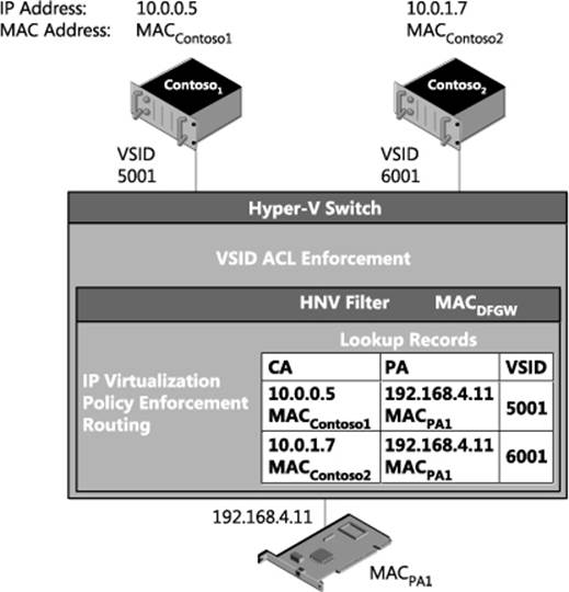
FIGURE 1-8 Packet flow for two VMs on different virtual subnets but the same host.
When Contoso1 communicates with Contoso2, the packet flow is as follows:
1. The IP addresses are on different subnets so Contoso1 sends ARP messages for the default gateway, not the IP address directly.
2. The Hyper-V switch broadcasts the ARP to the HNV filter.
3. The HNV filter responds to the ARP with MACDFGW. MACDFGW is associated with the HNV filter itself. As noted previously, the IP address associated with this MAC address is the .1 address in the virtual subnet, 10.0.0.1 in this case.
4. Contoso1 learns to use MACDFGW for the default gateway (10.0.0.1) on VSID 5001 (included in the OOB data for this MAC address).
5. Contoso1 sends an IP packet destined for Contoso2 with the MAC address of the default gateway so that the packet is delivered to the default gateway to be routed appropriately.
![]()
6. This packet is delivered to the Hyper-V switch and gets the VSID (5001) associated with the sender’s VM network adapter as out-of-band (OOB) data.
7. The HNV filter verifies Contoso1 and Contoso2 are in same VM network, otherwise the packet is dropped.
8. The HNV filter uses its lookup records to determine the PA of the destination VM. If there is no lookup record for the IP address, the packet is dropped.
![]()
In this scenario, the PA for the destination VM is the PA for the local HNV filter, so the HNV filter rewrites the packet to change the destination MAC address to MACContoso2.
9. The HNV filter updates the OOB data with the VSID to the destination VSID (6001).
NOTE Since the VSID is carried in the GRE key there is space in the packet for only one VSID. The destination VSID is put into the packet such that it can go with the packet over the wire.
10. Since the Hyper-V switch is an L2 switch, it knows all the MAC addresses of VMs attached to it. It also does the VSID ACL’ing. The switch sees that the packet is being sent to MACContoso2 on VSID 6001 and matches that with the VM network adapter for Contoso2.
11. The Hyper-V switch then delivers the packet to Contoso2.
This scenario shows how HNV acts as a router for the virtual network. A few things to emphasize are:
![]() When the two VMs are on the same host, there is no NVGRE encapsulation.
When the two VMs are on the same host, there is no NVGRE encapsulation.
![]() In contrast with VMs on the same virtual subnet, in this scenario the HNV filter receives and processes the packet because it is acting as the default gateway. This a good example of how HNV acts as a distributed router.
In contrast with VMs on the same virtual subnet, in this scenario the HNV filter receives and processes the packet because it is acting as the default gateway. This a good example of how HNV acts as a distributed router.
![]() When acting as the default gateway, the HNV filter updates the VSID and the destination MAC address of the packet to match the receiver’s VSID and MAC address.
When acting as the default gateway, the HNV filter updates the VSID and the destination MAC address of the packet to match the receiver’s VSID and MAC address.
Two VMs on the same virtual subnet, different hosts, dynamic IP address learning not enabled
The two previous packet flow examples showed what happens in HNV when VMs are on the same host. More commonly, however, VMs are on different Hyper-V hosts. The following example walks through the packet flow where two VMs are on the same virtual subnet but on different hosts. Figure 1-9 shows the setup in this scenario where the VMs are on different Hyper-V hosts but the same VSID. In the HNV filter, the configured lookup records are shown.

FIGURE 1-9 Packet flow for two VMs on the same virtual subnet, but on different hosts and with dynamic IP address learning not enabled.
When Contoso1 communicates with Contoso2, the packet flow is as follows:
1. Contoso1 sends ARP messages for 10.0.0.7.
2. The Hyper-V switch broadcasts the ARP to:
• All the local VMs on VSID 5001
• The HNV filter
3. The HNV filter responds to the ARP for IP address 10.0.0.7 on VSID 5001 on behalf of Contoso2 with MACContoso2.
NOTE The ARP is not broadcast to the network.
4. Contoso1 learns to use MACContoso2 for 10.0.0.7.
![]()
5. Contoso1 sends an IP packet destined for Contoso2.
6. This packet is delivered to the Hyper-V switch and gets the VSID associated with the packet as out-of-band (OOB) data.
7. The Hyper-V switch sees that MACContoso2 is not on the local Hyper-V switch and sends it to the HNV filter.
![]()
8. The HNV filter finds the lookup record associated, on the 5001 VSID, with the CA (10.0.0.7) and the MAC address (MACContoso2). It finds the PA (192.168.4.22) associated with this lookup record. With all the required information, it now encapsulates the original IP packet with an NVGRE packet that will be delivered on the wire.
NOTE The VSID (5001) is explicitly put into the packet and can be seen on the wire. The lighter shaded part of the packet is called the outer packet and the darker shaded part of the packet is called the inner packet.
9. The NVGRE encapsulated packet gets passed through the networking stack and on to the physical network adapter to the physical network infrastructure.
10. The physical network infrastructure uses the outer packet (destination MAC and IP address) to route the packet to the specified Hyper-V host.
11. The Hyper-V host corresponding to IP address 192.168.4.22 and MACPA2 receives the packet and delivers it to the HNV filter.
NOTE The PA is associated with the HNV filter. This is why the PA should not be the same IP address as the underlying physical NIC or NIC team.
12. The HNV filter de-encapsulates the packet and now has the inner packet (the original IP packet), plus the OOB data contains the VSID (5001).
13. The HNV filter delivers the IP packet (the inner packet from the previous step) to the Hyper-V switch with the corresponding OOB data containing the VSID (5001).
14. The Hyper-V switch does any required VSID ACL’ing and then delivers the IP packet to the VM. In this scenario, the packet was NVGRE encapsulated but the encapsulation was completely transparent to either the sending or receiving VM.
This packet flow includes NVGRE encapsulation and provides a more complete picture of how HNV typically works. A few things to emphasize are:
![]() When dynamic IP address learning is not enabled, even if the destination VM is not on the on the local host the ARP is processed by the HNV filter and doesn’t flow over the wire.
When dynamic IP address learning is not enabled, even if the destination VM is not on the on the local host the ARP is processed by the HNV filter and doesn’t flow over the wire.
![]() On the wire, the physical network routes the packet based on the outer packet (PA IP address and MAC address) and is unaware of the inner packet (CA IP address and MAC address).
On the wire, the physical network routes the packet based on the outer packet (PA IP address and MAC address) and is unaware of the inner packet (CA IP address and MAC address).
![]() Even when a packet is NVGRE encapsulated on the wire, this encapsulation is always transparent to the sending and receiving VMs.
Even when a packet is NVGRE encapsulated on the wire, this encapsulation is always transparent to the sending and receiving VMs.
Two VMs on the same virtual subnet, different hosts, dynamic IP address learning enabled
This scenario is a variant of the previous one only instead of a static lookup record being configured for a particular MAC address, an L2-only record is configured. Figure 1-10 shows the setup in this scenario where the VMs are on different Hyper-V hosts but the same VSID and an L2-only lookup record is configured. The figure shows the configured lookup records in the HNV filter, including the dynamic record indicated by the 0.0.0.0 IP address for Contoso2.
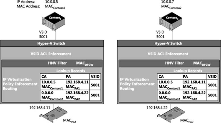
FIGURE 1-10 Packet flow when dynamic IP address learning is enabled for a MAC address.
When Contoso1 communicates with Contoso2 and dynamic IP address learning is enabled for a particular MAC address, the packet flow is as follows:
1. Contoso1 sends ARP messages for 10.0.0.7.
2. The Hyper-V switch broadcasts the ARP to:
• All the local VMs on VSID 5001
• The HNV filter
3. The HNV filter does not find a lookup record for the 10.0.0.7 IP address.
NOTE This will only happen the first time trying to communicate with an IP address. After this packet, flow happens once there are two lookup records for this MAC address. One is the L2-only record and the second is a newly created dynamic lookup record that matches the IP address with the MAC address. At this point the packet flow would be identical to the previous one.
![]()
4. The HNV creates a unicast ARP packet for each PA that has an L2-only record associated with it on the 5001 VSID.
NOTE Just like a physical network, ARPs are not broadcast outside the current subnet because a subnet is a broadcast boundary.
![]()
5. The HNV filter encapsulates the ARP request into an NVGRE packet.
6. The NVGRE encapsulated packet gets passed through the networking stack and on to the physical network adapter to the physical network infrastructure.
7. The physical network infrastructure uses the outer packet (destination MAC and IP address) to route the packet to the specified Hyper-V host.
8. The Hyper-V host corresponding to IP address 192.168.4.22 and MACPA2 receives the packet and delivers it to the HNV filter.
NOTE The PA is associated with the HNV filter. This is why the PA should not be the same IP address as the underlying physical NIC or NIC team.
9. The HNV filter de-encapsulates the packet and now has the inner packet (the original ARP packet), plus the OOB data contains the VSID (5001).
10. The HNV filter delivers the ARP packet (the inner packet from the previous step) to the Hyper-V switch with the corresponding OOB data containing the VSID (5001).
11. The Hyper-V switch does any required VSID ACL’ing and then delivers the ARP packet to the VM.
![]()
12. If the VM’s network adapter matches the MAC address in the ARP request it reply’s with an ARP reply packet and it is sent to the Hyper-V switch.
13. The Hyper-V switch attaches the OOB data with the VSID (5001).
14. The Hyper-V switch passes the ARP reply packet to the HNV filter since the packet is not destined for a local VM.
15. The HNV filter sees this is an ARP packet, and if there is no dynamic IP address record for this CA MAC/IP address and PA MAC/IP address pair for the local HNV filter, it will be added. Then a notification of a new dynamic record is sent to VMM so that the updated policy can be sent to other Hyper-V hosts.
![]()
16. The HNV filter finds a lookup record for the destination MAC address (MACContoso1) and encapsulates the packet for transportation on the physical network.
17. The NVGRE encapsulated packet is passed through the networking stack, to the physical network adapter, and then to the physical network infrastructure.
18. The physical network infrastructure uses the outer packet (destination MAC and IP Address) to route the packet to the specified Hyper-V host.
19. The Hyper-V host corresponding to IP address 192.168.4.11 and MACPA1 receives the packet and delivers it to the HNV filter.
NOTE The PA is associated with the HNV filter. This is why the PA should not be the same IP address as the underlying physical NIC or NIC team.
20. The HNV filter de-encapsulates the packet, and since it is an ARP packet, adds a dynamic record for the CA MAC/IP address and PA MAC/IP address pair. Notification of a new dynamic record is sent to VMM so that the updated policy can be sent to other Hyper-V hosts. The Hyper-V extensible switch then delivers the ARP packet to Contoso1.
21. Contoso1 learns to use MACContoso2 for 10.0.0.7.
![]()
22. Contoso1 sends an IP packet destined for Contoso2.
23. This packet is delivered to the Hyper-V switch and gets the VSID (5001) associated with the packet as out-of-band (OOB) data.
24. The Hyper-V switch sees that MACContoso2 is not on the local Hyper-V switch and sends it to the HNV filter.
![]()
25. The HNV filter finds the lookup record associated, on the 5001 VSID, with the CA (10.0.0.7) and the MAC address (MACContoso2). It finds the PA (192.168.4.22) associated with this lookup record. With all the required information, it now encapsulates the original IP packet with an NVGRE packet that will be delivered on the wire.
NOTE The VSID (5001) is explicitly put into the packet and can be seen on the wire. The lighter shaded part of the packet is called the outer packet and the darker shaded part of the packet is called the inner packet.
26. The NVGRE encapsulated packet is passed through the networking stack, to the physical network adapter, and then to the physical network infrastructure.
27. The physical network infrastructure uses the outer packet (destination MAC and IP address) to route the packet to the specified Hyper-V host.
28. The Hyper-V host corresponding to IP address 192.168.4.22 and MACPA2 receives the packet and delivers it to the HNV filter.
NOTE The PA is associated with the HNV filter. This is why the PA should not be the same IP address as the underlying physical NIC or NIC team.
29. The HNV filter de-encapsulates the packet and now has the inner packet (the original IP packet), plus the OOB data contains the VSID (5001).
30. The HNV filter delivers the IP packet (the inner packet from the previous step) to the Hyper-V switch with the corresponding OOB data containing the VSID (5001).
31. The Hyper-V switch does any required VSID ACL’ing and then delivers the IP packet to the VM. In this scenario, the packet was NVGRE encapsulated but the encapsulation was completely transparent to both the sending and receiving VM.
These steps show the packet flow when dynamic IP address learning is enabled. A few things to emphasize are:
![]() The ARP packets flow across the wire as unicast encapsulated packets.
The ARP packets flow across the wire as unicast encapsulated packets.
![]() The destination VM generates the actual ARP reply in this packet flow.
The destination VM generates the actual ARP reply in this packet flow.
![]() Neither the source nor the destination Hyper-V host has the CA MAC/IP address and PA MAC/IP address pair; it will be added as a new dynamic lookup record and VMM will be notified of the new lookup record.
Neither the source nor the destination Hyper-V host has the CA MAC/IP address and PA MAC/IP address pair; it will be added as a new dynamic lookup record and VMM will be notified of the new lookup record.
Two VMs on different virtual subnets, different hosts
The next scenario shows what happens when the VMs are on different Hyper-V hosts. This example walks through the packet flow where two VMs are on different virtual subnets and on the same host. Figure 1-11 shows the setup in this scenario with both VMs on different Hyper-V hosts and different VSID. The figure shows the configured lookup records in the HNV filter.
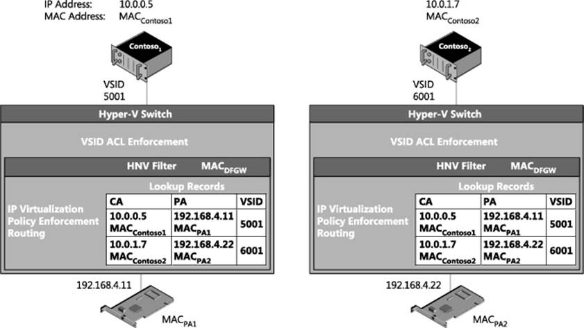
FIGURE 1-11 Packet flow for two VMs on different virtual subnets and different hosts.
When Contoso1 communicates with Contoso2, the packet flow is as follows:
1. The IP addresses are on different subnets so Contoso1 sends ARP messages for the default gateway, not the IP address directly.
2. The Hyper-V switch broadcasts the ARP to the HNV filter.
3. The HNV filter responds to the ARP with MACDFGW. MACDFGW is associated with the HNV filter itself. As noted previously, the IP address associated with this MAC address is the .1 address in the virtual subnet, 10.0.0.1 in this case.
4. Contoso1 learns to use MACDFGW for the default gateway (10.0.0.1) on VSID 5001 (included in the OOB data for this MAC address).
![]()
5. Contoso1 sends an IP packet destined for Contoso2 with the MAC address of the default gateway so that the packet is delivered to the default gateway to be routed appropriately.
6. This packet is delivered to the Hyper-V switch and gets the VSID associated (5001) with the sender’s VM network adapter as out-of-band (OOB) data.
7. The HNV filter verifies Contoso1 and Contoso2 are in same VM network, otherwise the packet is dropped.
8. The HNV filter uses its lookup records to determine the PA of the destination VM. If there is no lookup record for the IP address, the packet is dropped.
![]()
9. The HNV filter rewrites the packet to change the destination MAC address to MACContoso2.
![]()
10. The HNV filter finds the lookup record associated with the CA (10.0.1.7) and the MAC Address (MACContoso2). It sees the VSID (6001) associated with the lookup record is in the same VM network as the original VSID (5001) but is different. It uses the VSID (6001) of the destination VM network adapter when creating the NVGRE encapsulated packet. It finds the PA (192.168.4.22) associated with this lookup record. With all the required information, it now encapsulates the original IP packet with an NVGRE packet that will be delivered on the wire.
NOTE The VSID (6001) is explicitly put into the packet and can be seen on the wire. The lighter shaded part of the packet is called the outer packet and the darker shaded part of the packet is called the inner packet.
11. The NVGRE encapsulated packet is passed through the networking stack, to the physical network adapter, and then to the physical network infrastructure.
12. The physical network infrastructure uses the outer packet (destination MAC and IP address) to route the packet to the specified Hyper-V host.
13. The Hyper-V host corresponding to IP address 192.168.4.22 and MACPA2 receives the packet and delivers it to the HNV filter.
NOTE The PA is associated with the HNV filter. This is why the PA should not be the same IP address as the underlying physical NIC or NIC team.
14. The HNV filter de-encapsulates the packet and now has the inner packet (the original IP packet), plus the OOB data contains the VSID (6001).
15. The HNV filter delivers the IP packet (the inner packet from the previous step) to the Hyper-V switch with the corresponding OOB data containing the VSID (6001).
16. The Hyper-V switch does any required VSID ACL’ing and then delivers the IP packet to the VM. In this scenario, the packet was NVGRE encapsulated but the encapsulation was completely transparent to both the sending and receiving VMs.
This packet flow includes NVGRE encapsulation and provides a more complete picture of how HNV typically works. One thing to emphasize is that when sending packets on different subnets the destination VSID is used.
VM to a physical host through the inbox forwarding gateway
Figure 1-12 shows a packet flow configuration where a VM in a virtual network is communicating through a forwarding gateway to a physical server.
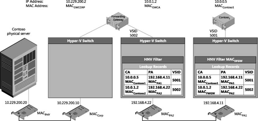
FIGURE 1-12 Forwarding gateway packet flow scenario.
When Contoso1 communicates with the Contoso physical server, the packet flow is as follows:
1. These IP addresses are on different subnets so Contoso1 sends ARP messages to the default gateway and not the IP address directly.
2. The Hyper-V switch broadcasts the ARP to the HNV filter.
3. The HNV filter responds to the ARP with MACDFGW. MACDFGW is associated with the HNV filter itself. As noted previously, the IP address associated with this MAC address is the .1 address in the virtual subnet, 10.0.0.1 in this case.
4. Contoso1 learns to use MACDFGW for the default gateway (10.229.202.1) on VSID 5001 (included in the OOB data for this MAC address).
![]()
5. Contoso1 sends an IP packet destined for the physical Contoso server with the MAC address of the default gateway so that the packet is delivered to the default gateway to be routed appropriately.
6. This packet is delivered to the Hyper-V switch and gets the VSID associated (5001) with the sender’s VM network adapter as out-of-band (OOB) data.
7. The HNV filter sees that there is a customer route for the 10.229.200.x subnet that points to 10.0.1.2 (the forwarding gateway) as the next hop address.
8. The HNV filter uses its lookup records to determine the PA of the next hop VM. If there is no lookup record for the IP address, the packet is dropped.
![]()
9. The HNV filter rewrites the packet to change the destination MAC address to MACGWCA (the MAC address of the forwarding gateway).
![]()
10. The HNV filter finds the lookup record associated with the CA (10.0.1.2) and the MAC address (MACGWCA). It sees the VSID (5002) associated with the lookup record is in the same VM network as the original VSID (5001) but is different. It uses the VSID (5002) of the destination VM network adapter when creating the NVGRE encapsulated packet. It finds the PA (192.168.4.22) associated with this lookup record. With all the required information, it now encapsulates the original IP packet with an NVGRE packet that will be delivered on the wire.
NOTE The VSID (5002) is explicitly put into the packet and can be seen on the wire. The lighter shaded part of the packet is called the outer packet and the darker shaded part of the packet is called the inner packet.
11. The NVGRE encapsulated packet is passed through the networking stack, to the physical network adapter, and then to the physical network infrastructure.
12. The physical network infrastructure uses the outer packet (destination MAC and IP address) to route the packet to the specified Hyper-V host.
13. The Hyper-V host corresponding to IP address 192.168.4.22 and MACPA2 receives the packet and delivers it to the HNV filter.
NOTE The PA is associated with the HNV filter. This is why the PA should not be the same IP address as the underlying physical NIC or NIC team.
14. The HNV filter de-encapsulates the packet and now has the inner packet (the original IP packet), plus the OOB data contains the VSID (5002).
15. The HNV filter delivers the IP packet (the inner packet from the previous step) to the Hyper-V switch with the corresponding OOB data containing the VSID (5002).
16. The Hyper-V switch does any required VSID ACL’ing and then delivers the IP packet to the VM. In this scenario, the packet was NVGRE encapsulated but the encapsulation was completely transparent to both the sending and receiving VMs.
17. At this point, the packet is in the forwarding gateway VM.
18. The forwarding gateway VM has been configured to forward packets between the two network interfaces in the VM.
![]()
19. The forwarding gateway VM’s network adapter connected to the physical network rewrites the destination MAC address to MACPHY (corresponding to the MAC address of the Contoso physical server).
20. The Contoso physical server receives the packet none the wiser that it was originated in a virtual network.
Hyper-V Network Virtualization: Simple setup
While most HNV deployments are performed using VMM, the basic concepts are best understood by doing a simple HNV deployment using Windows PowerShell. This section provides a step-by-step walkthrough on how to deploy an HNV network that includes a forwarding gateway. The result will be two VMs sitting in a virtual network with a forwarding gateway connecting them to the physical server. Figure 1-13 shows the setup and configuration. The walkthrough begins with Host 1, then goes through Host 2, then the gateway, and finally the physical machine.
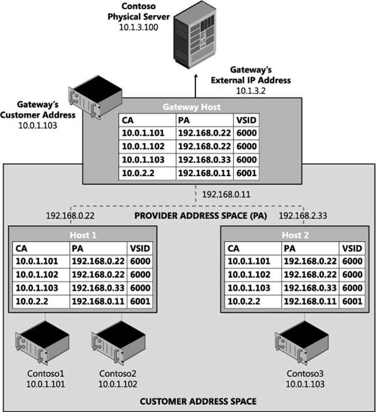
FIGURE 1-13 Simple HNV setup.
The setup prerequisites are as follows:
![]() Four physical hosts on the same L2 switch
Four physical hosts on the same L2 switch
• Each physical host running Windows Server 2012 R2
• Each host with a minimum of 8 gigabytes of RAM
• One host (the gateway host) with two network adapters.
![]() Four VHDs with Windows Server 2012 R2 installed
Four VHDs with Windows Server 2012 R2 installed
![]() Two of the VMs placed on Host 1, one on Host 2, and one on the gateway host
Two of the VMs placed on Host 1, one on Host 2, and one on the gateway host
NOTE You can get away with using only three physical hosts if you want to drop the third virtual machine on a separate host.
Host 1 setup
The sections that follow provide the steps for:
![]() Host 1 VM setup
Host 1 VM setup
![]() Host 1 HNV policy configuration
Host 1 HNV policy configuration
![]() Configuring Contoso1
Configuring Contoso1
![]() Configuring Contoso2
Configuring Contoso2
Host 1 VM setup
The steps for Host 1 VM setup are as follows:
1. Install Windows Server 2012 R2.
2. Install the Hyper-V role using the following command:
Instal1-WindowsFeature
-Name Hyper-V
-ComputerName localhost
-IncludeManagementTools
-Restart
NOTE Windows PowerShell must be run as Administrator for this command to work.
3. Create a virtual switch using the following command:
New-VMSwitch "HNVSwitch"
-NetAdapterName "Ethernet"
-AllowManagementOS 1
This creates a virtual switch. You might need to update the name of the – NetAdapterName parameter if your network adapter is not called “Ethernet”. Go to the Network And Sharing Center in Control Panel to determine the name of your network.
4. Create the VM for Contoso1. You will need to update the –VHDPath with the actual location of a VHD with Windows Server 2012 R2 installed.
New-VM
-Name "Contosol"
-VHDPath "Location of VHD"
-SwitchName "HNVSwitch"
-Generation 2
5. Create the VM for Contoso2. You will need to update the –VHDPath with the actual location of a VHD with Windows Server 2012 R2 installed.
New-VM
-Name "Contoso2"
-VHDPath "Location of VHD"
-SwitchName "HNVSwitch"
-Generation 2
6. Set the MAC address for the three VM network adapters to a static MAC address
NOTE This step is not required but makes the rest of the configuration easier.
Set-VMNetworkAdapter
-VMName "Contosol"
-StaticMacAddress 600060000101
Set-VMNetworkAdapter
-VMName "Contoso2"
-StaticMacAddress 600060000102
Host 1 HNV policy configuration
The steps for Host 1 HNV policy configuration are as follows:
1. Run an elevated PowerShell window. All the following steps will run in this PowerShell Window.
2. Configure the PA on the host. This PA should not be the IP address of the underlying NIC or NIC team. It should be routable on the network to and from any other host that has a VM using the same virtual network.
Siface =
((Get-VMSwitch -name "HNVSwitch").NetAdapterInterfaceDescription)).ifIndex)
New-NetVirtualizationProviderAddress
-ProviderAddress 192.168.0.22
-MacAddress 334455667788
-InterfaceIndex ((get-netadapter -InterfaceDescription $iface))
-PrefixLength 24
NOTE You can set a VLAN on a PA to associate the PA to a VLAN. You might want to do this if for instance you want all HNV traffic to be isolated and on the same VLAN.
3. Set the VSID on the three VM network adapters to the same VSID, in this case 6000. This is the command that specifies a VM network adapter should send virtualized network traffic.
Set-VMNetworkAdapter
-VMName "Contosol"
-VirtualSubnetId 6000
Set-VMNetworkAdapter
-VMName "Contoso2"
-VirtualSubnetId 6000
4. Configure the customer route for the 10.0.1.0/24 subnet. This is the IP address range for the virtual subnet 6000.
New-NetVirtualizationCustomerRoute
-RoutingDomainID "{12345678-1000-2000-3000-123456780001}"
-VirtualSubnetID 6000
-DestinationPrefix 10.0.1.0/24
-NextHop 0.0.0.0
NOTE This is where a VSID is assigned to a routing domain (called a VM network in VMM). Unlike a VSID which is explicitly carried in the packet, the routing domain is a logical concept that is enforced in the HNV module. HNV does all routing inside a routing domain. This means the next hop is “onlink” and HNV will handle all the routing. This is also where a VSID is assigned an IP address subnet. A virtual subnet supports all valid sized subnets so it is not required to be a /24 but can range from a /24 to a /30.
5. Configure the customer route for the Contoso gateway’s 10.0.2.0/24 subnet. This is the IP address range for the virtual subnet 6001. It is also the customer route for the HNV Gateway.
New-NetVirtualizationCustomerRoute
-RoutingDomainID "{12345678-1000-2000-3000-123456780001}"
-VirtualSubnetID 6001
-DestinationPrefix 10.0.2.0/24
-NextHop 0.0.0.0
NOTE The Gateway must be on its own VSID. This is because policy (as seen in the next step) is configured to send all traffic outside the virtual network through the Gateway as the next hop. This limits other VMs being on the same VSID as the Gateway. The Gateway and any VSID that has to go through the Gateway must be on the same routing domain.
6. Configure a wildcard route for Contoso’s routing domain. This route must be on the same VSID as the gateway and its next hop will be the IP address of the HNV Gateway.
New-NetVirtualizationCustomerRoute
-RoutingDomainID "{12345678-1000-2000-3000-123456780001}"
-VirtualSubnetID 6001
-DestinationPrefix 0.0.0.0/0
-NextHop 10.0.2.2
7. Configure a static route for the default gateway in the virtual subnet. The provider address should be the provider address of the host that this lookup record is being set on.
New-NetVirtualizationLookupRecord
-CustomerAddress 10.0.1.1
-VirtualSubnetID 6000
-MACAddress 600060000100
-ProviderAddress 192.168.0.22
-Type Static
-Rule TranslationMethodEncap
NOTE This is a new feature in Windows Server 2012 R2 that allows VMs on a virtualized network to ping the default HNV Gateway. This is a useful diagnostic mechanism to ensure based connectivity on a virtualized network. The default gateway for a subnet is fixed at the .1 address for that subnet.
8. Configure the lookup record for Contoso1 located on Host 1.
New-NetVirtualizationLookupRecord
-CustomerAddress 10.0.1.101
-VirtualSubnetID 6000
-MACAddress 600060000101
-ProviderAddress 192.168.0.22
-Rule TranslationMethodEncap
9. Configure the lookup record for Contoso2 located on Host 1.
New-NetVirtualizationLookupRecord
-CustomerAddress 10.0.1.102
-VirtualSubnetID 6000
-MACAddress 600060000102
-ProviderAddress 192.168.0.22
-Rule TranslationMethodEncap
10. Configure the lookup record for Contoso3 located on Host 2.
New-NetVirtualizationLookupRecord
-CustomerAddress 10.0.1.103
-VirtualSubnetID 6000
-MACAddress 600060000203
-ProviderAddress 192.168.0.33
-Rule TranslationMethodEncap
11. Configure the lookup record for Gateway located on the Gateway host.
New-NetVirtualizationLookupRecord
-CustomerAddress 10.0.2.2
-VirtualSubnetID 6001
-MACAddress 600160010301
-ProviderAddress 192.168.0.11
-Rule TranslationMethodEncap
You can validate the setup by running the four commands described next.
Get-VMNetworkAdapter
The Get-VMNetworkAdapter cmdlet gets the virtual network adapters of the specified virtual machine, snapshot, or management operating system:
Get-VMNetworkAdapter * | fl VMName,MacAddress,VirtualSubnetId,SwitchName
The output from this command should look like this:
VMName : Contosol
MacAddress : 600060000101
VirtualSubnetId : 6000
SwitchName : HNVSwitch
VMName : Contoso2
MacAddress : 600060000102
VirtualSubnetId : 6000
SwitchName : HNVSwitch
Get-NetVirtualizationCustomerRoute
The Get-NetVirtualizationCustomerRoute cmdlet gets virtual network routes in a virtual network:
Get-NetVirtualizationCustomerRoute
The output from this command should look like this:
RoutingDomainID: {12345678-1000-2000-3000-123456780001}
VirtualSubnetID: 6000
DestinationPrefix: 10.0.1.0/24
NextHop: 0.0.0.0
Metric: 0
RoutingDomainID: {12345678-1000-2000-3000-123456780001}
VirtualSubnetID: 6001
DestinationPrefix: 10.0.2.0/24
NextHop: 0.0.0.0
Metric: 0
RoutingDomainID: {12345678-1000-2000-3000-123456780001}
VirtualSubnetID: 6001
DestinationPrefix: 0.0.0.0/0
NextHop: 10.0.2.2
Metric: 0
Get-NetVirtualizationLookupRecord
The Get-NetVirtualizationLookupRecord cmdlet gets lookup record policy entries for IP addresses that belong to a virtual network:
Get-NetVirtualizationLookupRecord
The output from this command should look like this:
CustomerAddress: 10.0.1.1
VirtualSubnetID: 6000
MACAddress: 600060000100
ProviderAddress: 192.168.0.22
CustomerID: {00000000-0000-0000-0000-000000000000}
Context:
Rule: TranslationMethodEncap
VMName:
UseVmMACAddress: False
Type: Static
CustomerAddress: 10.0.1.101
VirtualSubnetID: 6000
MACAddress: 600160010101
ProviderAddress: 192.168.0.22
CustomerID: {00000000-0000-0000-0000-000000000000}
Context:
Rule: TranslationMethodEncap
VMName:
UseVmMACAddress: False
Type: Static
CustomerAddress: 10.0.1.102
VirtualSubnetID: 6000
MACAddress: 600160010102
ProviderAddress: 192.168.0.22
CustomerID: {00000000-0000-0000-0000-000000000000}
Context:
Rule: TranslationMethodEncap
VMName:
UseVmMACAddress: False
Type: Static
CustomerAddress: 10.0.1.103
VirtualSubnetID: 6000
MACAddress: 600160010203
ProviderAddress: 192.168.0.33
CustomerID: {00000000-0000-0000-0000-000000000000}
Context:
Rule: TranslationMethodEncap
VMName:
UseVmMACAddress: False
Type: Static
CustomerAddress: 10.0.2.2
VirtualSubnetID: 6001
MACAddress: 600160010301
ProviderAddress: 192.168.0.11
CustomerID: {00000000-0000-0000-0000-000000000000}
Context:
Rule: TranslationMethodEncap
VMName:
UseVmMACAddress: False
Type: Static
Get-NetVirtualizationProviderAddress
The Get-NetVirtualizationProviderAddress cmdlet gets provider addresses configured in Hyper-V Network Virtualization:
Get-NetVirtualizationProviderAddress
The output from this command should look like this:
ProviderAddress: 192.168.0.22
InterfaceIndex: 12
PrefixLength: 24
VlanID: 0
AddressState: Preferred
MACAddress: 334455667788
ManagedByCluster: False
Configuring Contoso1
The steps for configuring Contoso1 are as follows:
1. Start the Contoso1 VM on Host1.
2. Log into the VM and run an elevated PowerShell window. All the following steps will run in this PowerShell window.
3. Configure the Contoso1 VM’s NIC to have a static IP address that matches the IP address of the VM.
$wmi = Cet-WmiObject win32_networkadapterconfiguration
-filter "ipenabled = 'true'"
$wmi.EnableStatic("10.0.1.101", "255.255.255.0")
$wmi.SetCateways("10.0.1.1", 1)
4. Configure Windows Firewall to allow pings.
Import-Module NetSecurity
Set-NetFirewal1Ruie
-DisplayName "File and Printer Sharing (Echo Request - ICMPv4-In)"
-enabled True
5. On the Contoso1 VM, you should now be able to ping the default gateway.
ping 10.0.1.1
Configuring Contoso2
The steps for configuring Contoso2 are as follows:
1. Start the Contoso2 VM on Host1.
2. Log into the VM and run an elevated PowerShell window. All the following steps will run in this PowerShell window.
3. Configure the Contoso2 VM’s NIC to have a static IP address that matches the IP address of the VM.
$wmi = Get-WmiObject win32_networkadapterconfiguration
-filter "ipenabled = 'true'"
$wmi.EnableStati c("10.0.1.102", "255.255.255.0")
$wmi.SetCateways("10.0.1.1", 1)
4. Configure Windows Firewall to allow pings.
Import-Module NetSecurity
Set-NetFi rewal1 Rui e
-DisplayName "File and Printer Sharing (Echo Request - ICMPv4-In)"
-enabled True
5. On the Contoso2 VM, you should now be able to ping both the default gateway and Contoso1.
ping 10.0.1.1
ping 10.0.1.101
6. On the Contoso1 VM, you should now be able to ping Contoso2.
ping 10.20.20.102
Congratulations! If this is working, you have a virtual network up and running!
Host 2 setup
The sections that follow provide the steps for:
![]() Host 2 VM setup
Host 2 VM setup
![]() Host 2 HNV policy configuration
Host 2 HNV policy configuration
![]() Contoso3 configuration
Contoso3 configuration
Host 2 VM setup
The steps for Host 2 VM setup are as follows:
1. Install Windows Server 2012 R2.
2. Install the Hyper-V role using the following command:
Instal1-WindowsFeature
-Name Hyper-V
-ComputerName local host
-IncludeManagementTools
-Restart
NOTE Windows PowerShell must be run as Administrator for this command to work.
3. Create a virtual switch using the following command:
New-VMSwitch "HNVSwitch"
-NetAdapterName "Ethernet"
-AllowManagementOS 1
You might need to update the name of the –NetAdapterName parameter if your network adapter is not called “Ethernet”. Go to the Network and Sharing Center in Control Panel to determine the name of your network adapter.
4. Create the VM for Contoso3. You will need to update the –VHDPath with the actual location of a VHD with Windows Server 2012 R2 installed.
New-VM
-Name "Contoso3"
-VHDPath "Location of VHD"
-SwitchName "HNVSwitch"
-Generation 2
5. Set the MAC address for the three VM network adapters to a static MAC address.
Set-VMNetworkAdapter
-VMName "Contoso3"
-StaticMacAddress 600060000203
NOTE This step is not required but makes the rest of the configuration easier.
Host 2 HNV policy configuration
The steps for Host 2 HNV policy configuration are as follows:
1. Run an elevated PowerShell window. All the following steps will run in this PowerShell window.
2. Configure the PA address on the host. This PA should not be the IP address of the underlying NIC or NIC team. It should be routable on the network to and from any other host that has VM using the same virtual network.
$iface =
((Get-VMSwi tch -name "HNVSwitch").NetAdapterInterfaceDescription)).ifIndex)
New-NetVirtualizationProviderAddress
-ProviderAddress 192.168.0.33
-MacAddress 445566778899
-InterfaceIndex ((get-netadapter -InterfaceDescription $iface))
-PrefixLength 24
NOTE On the provider address, you can set a VLAN. This associates a PA to a VLAN. You might want to do this if for instance you want all HNV traffic to be isolated and on the same VLAN. The PA assigned to this host must be different then the PA assigned to Host 1.
3. Set the VSID on the three VM network adapters to the same VSID, in this case 6000. This is the command that specifies a VM network adapter should send virtualized network traffic.
Set-VMNetworkAdapter
-VMName "Contosol"
-VirtualSubnetId 6000
4. Configure the customer route for the 10.0.1.0/24 subnet. This is the IP address range for the virtual subnet 6000.
New-NetVirtualizationCustomerRoute
-RoutingDomainID "{12345678-1000-2000-3000-123456780001}"
-VirtualSubnetID 6000
-DestinationPrefix 10.0.1.0/24
-NextHop 0.0.0.0
5. Configure the customer route for the Contoso gateway’s 10.0.2.0/24 subnet. This is the IP address range for the virtual subnet 6001. It is also the customer route for the HNV Gateway.
New-NetVirtualizationCustomerRoute
-RoutingDomainID "{12345678-1000-2000-3000-123456780001}"
-VirtualSubnetID 6001
-DestinationPrefix 10.0.2.0/24
-NextHop 0.0.0.0
6. Configure the wildcard route for Contoso’s routing domain. This route must be on the same VSID as the gateway and its next hop will be the IP address of the HNV Gateway.
New-NetVirtualizationCustomerRoute
-RoutingDomainID "{12345678-1000-2000-3000-123456780001}"
-VirtualSubnetID 6001
-DestinationPrefix 0.0.0.0/0
-NextHop 10.0.2.2
7. Configure a static route for the default gateway in the virtual subnet. The provider address should be the provider address of the host that this lookup record is being set on.
New-NetVirtualizationLookupRecord
-CustomerAddress 10.0.1.1
-VirtualSubnetID 6000
-MACAddress 600060000200
-ProviderAddress 192.168.0.33
-Type Static
-Rule TranslationMethodEncap
8. Configure the lookup record for Contoso1 located on Host 1.
New-NetVirtualizationLookupRecord
-CustomerAddress 10.0.1.101
-VirtualSubnetID 6000
-MACAddress 600060000101
-ProviderAddress 192.168.0.22
-Rule TranslationMethodEncap
9. Configure the lookup record for Contoso2 located on Host 1.
New-NetVirtualizationLookupRecord
-CustomerAddress 10.0.1.102
-VirtualSubnetID 6000
-MACAddress 600060000102
-ProviderAddress 192.168.0.22
-Rule TranslationMethodEncap
10. Configure the lookup record for Contoso3 located on Host 2.
New-NetVirtualizationLookupRecord
-CustomerAddress 10.0.1.103
-VirtualSubnetID 6000
-MACAddress 600060000203
-ProviderAddress 192.168.0.33
-Rule TranslationMethodEncap
11. Configure the lookup record for Gateway located on the Gateway host.
New-NetVirtualizationLookupRecord
-CustomerAddress 10.0.2.2
-VirtualSubnetID 6001
-MACAddress 600160010301
-ProviderAddress 192.168.0.11
-Rule TranslationMethodEncap
You can validate the setup by running the four commands described next.
Get-VMNetworkAdapter
The Get-VMNetworkAdapter cmdlet gets the virtual network adapters of the specified virtual machine, snapshot, or management operating system:
Get-vmnetworkadapter * | fl VMName,MacAddress,VirtualSubnetId,SwitchName
The output from this command should look like this:
VMName: Contoso3
MacAddress: 600060000203
VirtualSubnetId: 6000
SwitchName: HNVSwitch
Get-NetVirtualizationCustomerRoute
The Get-NetVirtualizationCustomerRoute cmdlet gets virtual network routes in a virtual network:
Get-NetVirtualizationCustomerRoute
The output from this command should look like this:
RoutingDomainID: {12345678-1000-2000-3000-123456780001}
VirtualSubnetID: 6000
DestinationPrefix: 10.0.1.0/24
NextHop: 0.0.0.0
Metric: 0
RoutingDomainID: {12345678-1000-2000-3000-123456780001}
VirtualSubnetID: 6001
DestinationPrefix: 10.0.2.0/24
NextHop: 0.0.0.0
Metric: 0
RoutingDomainID: {12345678-1000-2000-3000-123456780001}
VirtualSubnetID: 6001
DestinationPrefix: 0.0.0.0/0
NextHop: 10.0.2.2
Metric: 0
Get-NetVirtualizationLookupRecord
The Get-NetVirtualizationLookupRecord cmdlet gets lookup record policy entries for IP addresses that belong to a virtual network:
Get-NetVirtualizationLookupRecord
The output from this command should look like this:
CustomerAddress: 10.0.1.1
VirtualSubnetID: 6000
MACAddress: 600060000100
ProviderAddress: 192.168.0.22
CustomerID: {00000000-0000-0000-0000-000000000000}
Context:
Rule: TranslationMethodEncap
VMName:
UseVmMACAddress: False
Type: Static
CustomerAddress: 10.0.1.101
VirtualSubnetID: 6000
MACAddress: 600160010101
ProviderAddress: 192.168.0.22
CustomerID: {00000000-0000-0000-0000-000000000000}
Context:
Rule: TranslationMethodEncap
VMName:
UseVmMACAddress: False
Type: Static
CustomerAddress: 10.0.1.102
VirtualSubnetID: 6000
MACAddress: 600160010102
ProviderAddress: 192.168.0.22
CustomerID: {00000000-0000-0000-0000-000000000000}
Context:
Rule: TranslationMethodEncap
VMName:
UseVmMACAddress: False
Type: Static
CustomerAddress: 10.0.1.103
VirtualSubnetID: 6000
MACAddress: 600160010203
ProviderAddress: 192.168.0.33
CustomerID: {00000000-0000-0000-0000-000000000000}
Context:
Rule: TranslationMethodEncap
VMName:
UseVmMACAddress: False
Type: Static
CustomerAddress: 10.0.2.2
VirtualSubnetID: 6001
MACAddress: 600160010301
ProviderAddress: 192.168.0.11
CustomerID: {00000000-0000-0000-0000-000000000000}
Context:
Rule: TranslationMethodEncap
VMName:
UseVmMACAddress: False
Type: Static
Get-NetVirtualizationProviderAddress
The Get-NetVirtualizationProviderAddress cmdlet gets provider addresses configured in Hyper-V Network Virtualization:
Get-NetVirtualizationProviderAddress
The output from this command should look like this:
ProviderAddress: 192.168.0.33
InterfaceIndex: 12
PrefixLength: 24
VlanID: 0
AddressState: Preferred
MACAddress: 445566778899
ManagedByCluster: False
Configuring Contoso3
The steps for configuring Contoso3 are as follows:
1. Start the Contoso3 VM on Host 2.
2. Log into the VM and run an elevated PowerShell window. All the following steps will run in this PowerShell window.
3. Configure the Contoso3 VM’s NIC to have a static IP address that matches the IP address of the VM
$wmi = Get-WmiObject win32_networkadapterconfiguration
-filter "ipenabled = 'true'"
$wmi.EnableStatic("10.0.1.103", "255.255.255.0")
$wmi.SetCateways("10.0.1.1", 1)
4. Configure Windows Firewall to allow pings.
Import-Module NetSecurity
Set-NetFirewal1Ruie
-DisplayName "File and Printer Sharing (Echo Request - ICMPv4-In)"
-enabled True
5. On the Contoso3 VM, you should now be able to ping the default gateway, Contoso1, and Contoso2
ping 10.0.1.1
ping 10.0.1.101
ping 10.0.1.102
Gateway host setup
The sections that follow provide the steps for:
![]() Gateway VM setup
Gateway VM setup
![]() Gateway host HNV policy configuration
Gateway host HNV policy configuration
![]() MT-GW configuration
MT-GW configuration
Gateway VM setup
The steps for Gateway VM setup are as follows:
1. Install Windows Server 2012 R2.
2. Install the Hyper-V role using the following command:
Instal1-WindowsFeature
-Name Hyper-V
-ComputerName localhost
-IncludeManagementTools
-Restart
NOTE Windows PowerShell must be run as Administrator for this command to work.
3. Create a virtual switch for the HNV network using the following command:
New-VMSwitch "HNVSwitch"
-NetAdapterName "Ethernet"
-AllowManagementOS 1
You might need to update the name of the –NetAdapterName parameter if your network adapter is not called “Ethernet”. Go to the Network and Sharing Center in Control Panel to determine the name of your network adapter.
4. Create a virtual switch for the external network that will connect to the physical server.
New-VMSwitch "ExternalSwich"
-NetAdapterName "Ethernet2"
-AllowManagementOS 1
You might need to update the name of the –NetAdapterName parameter if your network adapter is not called “Ethernet2”. Go to the Network and Sharing Center in Control Panel to determine the name of your network adapter.
5. Create the VM for MT-GW. You will need to update the –VHDPath with the actual location of a VHD with Windows Server 2012 R2 installed.
New-VM
-Name "MT-Gw"
-VHDPath "Location of VHD"
-Generation 2
6. Create a VM network adapter on the “External” virtual switch in the MT-GW VM.
Add-VMNetworkAdapter
-VMName MT-GW
-Name IntNIC
-SwitchName "HNVSwitch"
7. Set the MAC address for the VM network adapter on the HNV network to a static MAC address.
Set-VMNetworkAdapter
-VMName "MT-Gw"
-StaticMacAddress 600160010301
NOTE This step is not required but makes the rest of the configuration easier.
8. Create a VM network adapter on the “External” virtual switch in the MT-GW VM.
Add-VMNetworkAdapter
-VMName MT-GW
-Name ExtNIC
-SwitchName "ExternalSwitch"
9. Set the MAC address for the VM network adapter on the External network to a static MAC address.
Set-VMNetworkAdapter
-VMName "MT-GW"
-StaticMacAddress 600160010302
NOTE This step is not required but makes the rest of the configuration easier.
Gateway host HNV policy configuration
The steps for Gateway host HNV policy configuration are as follows:
1. Run an elevated PowerShell window. All the following steps will run in this PowerShell window.
2. Configure the PA address on the host. This PA should not be the IP address of the underlying NIC or NIC team. It should be routable on the network to and from any other host that has a VM using the same virtual network.
$iface =
((Get-VMSwitch -name "HNVSwitch").NetAdapterInterfaceDescription)).ifIndex)
New-NetVirtualizationProviderAddress
-ProviderAddress 192.168.0.11
-MacAddress 223344556677
-InterfaceIndex ((get-netadapter -InterfaceDescription $iface -PrefixLength 24 ))
3. Set the VSID on the VM network adapters to the Gateway’s VSID, in this case 6001. This is the command that specifies a VM network adapter should send virtualized network traffic.
Set-VMNetworkAdapter
-VMName "MT-GW"
-VirtualSubnetId 6001
4. Configure the customer route for the 10.0.1.0/24 subnet. This is the IP address range for the virtual subnet 6000.
New-NetVirtualizationCustomerRoute
-RoutingDomainID "{12345678-1000-2000-3000-123456780001}"
-VirtualSubnetID 6000
-DestinationPrefix 10.0.1.0/24
-NextHop 0.0.0.0
5. Configure the customer route for the Contoso gateway’s 10.0.2.0/24 subnet. This is the IP address range for the virtual subnet 6001. It is also the customer route for the HNV Gateway.
New-NetVirtualizationCustomerRoute
-RoutingDomainID "{12345678-1000-2000-3000-123456780001}"
-VirtualSubnetID 6001
-DestinationPrefix 10.0.2.0/24
-NextHop 0.0.0.0
6. Configure the wildcard route for Contoso’s routing domain. This route must be on the same VSID as the gateway and its next hop will be the IP address of the HNV Gateway.
New-NetVirtualizationCustomerRoute
-RoutingDomainID "{12345678-1000-2000-3000-123456780001}"
-VirtualSubnetID 6001
-DestinationPrefix 0.0.0.0/0
-NextHop 10.0.2.2
7. Configure a static route for the default gateway in the virtual subnet. The provider address should be the provider address of the host that this lookup record is being set on.
New-NetVirtualizationLookupRecord
-CustomerAddress 10.0.2.1
-VirtualSubnetID 6001
-MACAddress 600160010300
-ProviderAddress 192.168.0.33
-Type Static
-Rule TranslationMethodEncap
8. Configure the lookup record for Contoso1 located on Host 1.
New-NetVirtualizationLookupRecord
-CustomerAddress 10.0.1.101
-VirtualSubnetID 6000
-MACAddress 600060000101
-ProviderAddress 192.168.0.22
-Rule TranslationMethodEncap
9. Configure the lookup record for Contoso2 located on Host 1.
New-NetVirtualizationLookupRecord
-CustomerAddress 10.0.1.102
-VirtualSubnetID 6000
-MACAddress 600060000102
-ProviderAddress 192.168.0.22
-Rule TranslationMethodEncap
10. Configure the lookup record for Contoso3 located on Host 2.
New-NetVirtualizationLookupRecord
-CustomerAddress 10.0.1.103
-VirtualSubnetID 6000
-MACAddress 600060000203
-ProviderAddress 192.168.0.33
-Rule TranslationMethodEncap
11. Configure the lookup record for Gateway located on the Gateway host.
New-NetVirtualizationLookupRecord
-CustomerAddress 10.0.2.2
-VirtualSubnetID 6001
-MACAddress 600160010301
-ProviderAddress 192.168.0.11
-Rule TranslationMethodEncap
12. Set the VM network adapter isolation mode for the gateway.
Set-VMNetworkAdapterlsolation
-VMName MT-GW
-VMNetworkAdapterName IntNic
-MultiTenantStack on
-IsolationModeNativeVirtualSubnet
13. Map a routing domain in the MT-GW to a VM network adapter on the host virtual switch.
Add-VmNetworkAdapterRoutingDomainMapping
-VMName MT-GW
-VMNetworkAdapterName IntNic
-RoutingDomainld "{00000000-0000-0000-0000-000000000000}"
-RoutingDomainName "ContosoTenant"
-IsolationId 6001
-IsolationName "ContosoGWSubnet"
You can validate the setup by running the four commands described next.
Get-VMNetworkAdapter
The Get-VMNetworkAdapter cmdlet gets the virtual network adapters of the specified virtual machine, snapshot, or management operating system:
Get-VMNetworkAdapter * | fl VMName,MacAddress,VirtualSubnetId,SwitchName
The output from this command should look like this:
VMName: MT-GW
MacAddress: 600160010301
VirtualSubnetId: 6001
SwitchName: HNVSwitch
Get-NetVirtualizationCustomerRoute
The Get-NetVirtualizationCustomerRoute cmdlet gets virtual network routes in a virtual network:
Get-NetVirtualizationCustomerRoute
The output from this command should look like this:
RoutingDomainID: {12345678-1000-2000-3000-123456780001}
VirtualSubnetID: 6000
DestinationPrefix: 10.0.1.0/24
NextHop: 0.0.0.0
Metric: 0
RoutingDomainID: {12345678-1000-2000-3000-123456780001}
VirtualSubnetID: 6001
DestinationPrefix: 10.0.2.0/24
NextHop: 0.0.0.0
Metric: 0
RoutingDomainID: {12345678-1000-2000-3000-123456780001}
VirtualSubnetID: 6001
DestinationPrefix: 0.0.0.0/0
NextHop: 10.0.2.2
Metric: 0
Get-NetVirtualizationLookupRecord
The Get-NetVirtualizationLookupRecord cmdlet gets lookup record policy entries for IP addresses that belong to a virtual network:
Get-NetVirtualizationLookupRecord
The output from this command should look like this:
CustomerAddress: 10.0.1.1
VirtualSubnetID: 6000
MACAddress: 600060000100
ProviderAddress: 192.168.0.22
CustomerID: {00000000-0000-0000-0000-000000000000}
Context:
Rule: TranslationMethodEncap
VMName:
UseVmMACAddress: False
Type: Static
CustomerAddress: 10.0.1.101
VirtualSubnetID: 6000
MACAddress: 600160010101
ProviderAddress: 192.168.0.22
CustomerID: {00000000-0000-0000-0000-000000000000}
Context:
Rule: TranslationMethodEncap
VMName:
UseVmMACAddress: False
Type: Static
CustomerAddress: 10.0.1.102
VirtualSubnetID: 6000
MACAddress: 600160010102
ProviderAddress: 192.168.0.22
CustomerID: {00000000-0000-0000-0000-000000000000}
Context:
Rule: TranslationMethodEncap
VMName:
UseVmMACAddress: False
Type: Static
CustomerAddress: 10.0.1.103
VirtualSubnetID: 6000
MACAddress: 600160010203
ProviderAddress: 192.168.0.33
CustomerID: {00000000-0000-0000-0000-000000000000}
Context:
Rule: TranslationMethodEncap
VMName:
UseVmMACAddress: False
Type: Static
CustomerAddress: 10.0.2.2
VirtualSubnetID: 6001
MACAddress: 600160010301
ProviderAddress: 192.168.0.11
CustomerID: {00000000-0000-0000-0000-000000000000}
Context:
Rule: TranslationMethodEncap
VMName:
UseVmMACAddress: False
Type: Static
Get-NetVirtualizationProviderAddress
The Get-NetVirtualizationProviderAddress cmdlet gets provider addresses configured in Hyper-V Network Virtualization:
Get-NetVirtualizationProviderAddress
The output from this command should look like this:
ProviderAddress: 192.168.0.11
InterfaceIndex: 12
PrefixLength: 24
VlanID: 0
AddressState: Preferred
MACAddress: 223344556677
ManagedByCluster: False
Configuring MT-GW
The steps for configuring MT-GW are as follows:
1. Start the MT-GW VM on the gateway host.
2. Log into the VM and run an elevated PowerShell window. All the following steps will run in this PowerShell window.
3. Configure Windows Firewall to allow pings.
Import-Module NetSecurity
Set-NetFirewal1Ruie
-DisplayName "File and Printer Sharing (Echo Request - ICMPv4-In)"
-enabled True
4. Set the IP address of the internal NIC on the gateway that is connected to the virtual network.
New-NetlPAddress 10.0.2.2
-InterfaceAlias "ContosoCWSubnet"
-PrefixLength 24
5. Add a new netroute to the gateway because there is no default route for each tenant. Routes to the tenants’ subnets must explicitly be added and the next hop should be set to the .1 default gateway.
New-NetRoute
-InterfaceAlias "ContosoCWSubnet"
-AddressFamily IPv4
-DestinationPrefix 10.0.1.0/24
-NextHop 10.0.2.1
6. Enable forwarding on the external NIC.
Set-NetIPInterface -InterfaceAlias "External" -Forwarding Enabled
NOTE You will need to replace the InterfaceAlias property with the InterfaceAlias of the NIC that will be used for the physical network.
7. Enable forwarding on the ContosoGWSubnet network interface that was created in Step 5.
Set-NetlPInterface
-InterfaceAlias "ContosoCWSubnet"
-Forwarding Enabled
8. Configure the IP address for the external IP address.
New-NetlPAddress
-InterfaceAlias "External"
-IPAddress 10.1.3.2
-PrefixLength 24
NOTE You will need to replace the InterfaceAlias property with the InterfaceAlias of the NIC that will be used for the physical network.
9. On the MT-GW VM, you should now be able to ping the default gateway, Contoso1, Contoso2, and Contoso3.
ping 10.0.2.1
ping 10.0.1.101
ping 10.0.1.102
ping 10.0.1.103
Contoso physical host setup
The steps for the Contoso physical host setup are as follows:
1. Install Windows Server 2012 R2.
2. Configure the IP address of the physical host using the following command:
New-NetlPAddress
-InterfaceAlias "Ethernet 2"
-IPAddress 10.1.3.100
-PrefixLength 24
Replace the InterfaceAlias property with the InterfaceAlias of the NIC that will be used for the physical network.
3. Configure the IP address of the external NIC of the gateway to be the next hop for the 10.0.1.X subnet in the virtual network.
New-NetRoute
-InterfaceAlias "Ethernet 2"
-DestinationPrefix 10.0.1.0/24
-NextHop 10.1.3.2
Replace the InterfaceAlias property with the InterfaceAlias of the NIC that will be used for the external network.
4. Configure the IP address of the external NIC of the gateway to be the next hop for the 10.0.2.X subnet in the virtual network.
New-NetRoute
-InterfaceAlias "Ethernet 2"
-DestinationPrefix 10.0.2.0/24
-NextHop 10.1.3.2.0.1
Replace the InterfaceAlias property with the InterfaceAlias of the NIC that will be used for the external network.
5. Configure Windows Firewall to allow pings.
Import-Module NetSecurity
Set-NetFirewal1Ruie
-DisplayName "File and Printer Sharing (Echo Request - ICMPv4-In)'
-enabled True
With these last commands, you should now be able to ping between all five of the servers (Contoso1, Contoso2, Contoso3, MT-GW, and the Contoso physical host) participating in the network. You can use Message Analyzer to look at the packets flowing as you do the pings to validate that they match the packet flows discussed in the previous section.
All materials on the site are licensed Creative Commons Attribution-Sharealike 3.0 Unported CC BY-SA 3.0 & GNU Free Documentation License (GFDL)
If you are the copyright holder of any material contained on our site and intend to remove it, please contact our site administrator for approval.
© 2016-2026 All site design rights belong to S.Y.A.