Microsoft System Center: Network Virtualization and Cloud Computing (2014)
CHAPTER 2
Implementing cloud computing with Network Virtualization
The previous chapter examined the internal workings of Hyper-V Network Virtualization (HNV). This chapter will identify some key cloud computing scenarios and examine how HNV helps cloud service providers enable these scenarios. It will also cover the different gateway functionalities in Windows Server 2012 R2.
Key cloud computing scenarios enabled by HNV
Cloud computing enables organizations to leverage the compute, storage, and networking infrastructure of a cloud services provider to meet their business needs with agility and minimal capital expenditure. Without leveraging cloud computing, catering to dynamic compute needs would consume significant resources and time for a business. HNV helps cloud service providers offer cost-effective infrastructure as a service (IaaS) to their customers. The following are some of the key scenarios enabled by HNV:
![]() Cloud hosting
Cloud hosting
![]() Cloud bursting
Cloud bursting
![]() Cloud-based disaster recovery
Cloud-based disaster recovery
Cloud hosting
To understand a cloud hosting scenario, consider the requirements of two organizations, Woodgrove Bank and Contoso, Ltd., and how a cloud service provider named Fabrikam is able to fulfill these requirements using HNV. Woodgrove Bank wants to deploy a two-tier mobile application. The first tier consists of a web front-end while the second tier consists of multiple compute-intensive backend application servers that service the mobile application. The number of second tier servers required depends on the number of client connections at any given point in time. Given the dynamic nature of the client connections, in a traditional environment, Woodgrove Bank would have to deploy enough redundant servers to cater to peak demand. The problem with this approach is that during non-peak hours the deployed servers remain idle, accruing avoidable capital expenditure (CapEx) and operational expenditure (OpEx). But if Woodgrove Bank deploys the application on virtual machines (VMs) hosted on the Fabrikam infrastructure, they avoid the CapEx and OpEx of idle servers since they pay only for the actual usage of the servers.
Now consider the networking requirements of Woodgrove Bank's deployment in the Fabrikam network. Woodgrove Bank's mobile application needs to be reachable over the Internet, so they need at least one public IP address to which initial connections can be established. For the rest of their VMs, Woodgrove Bank chooses to assign IP addresses from the private IP address range (10.0.0.0/24). Fabrikam has to design their infrastructure in a way that not only meets the requirements of Woodgrove Bank but also the similar needs of other customers. Here’s are the different options Fabrikam has for doing this and the disadvantages of each approach:
![]() Isolated physical networks Fabrikam creates a subnet 10.0.0.0/24 in their physical network for Woodgrove Bank and connects Woodgrove Bank’s VMs to this subnet. The advantage of this approach is that Fabrikam can offer “bring your own IP or subnet” cloud services to multiple customers with overlapping IP address ranges. The disadvantage is that another customer, such as Contoso, cannot be allocated the same subnet (10.0.0.0/24). As a result, Fabrikam must create a separate physical network for each tenant. This limits the flexibility Fabrikam can offer to customers and impedes business scalability.
Isolated physical networks Fabrikam creates a subnet 10.0.0.0/24 in their physical network for Woodgrove Bank and connects Woodgrove Bank’s VMs to this subnet. The advantage of this approach is that Fabrikam can offer “bring your own IP or subnet” cloud services to multiple customers with overlapping IP address ranges. The disadvantage is that another customer, such as Contoso, cannot be allocated the same subnet (10.0.0.0/24). As a result, Fabrikam must create a separate physical network for each tenant. This limits the flexibility Fabrikam can offer to customers and impedes business scalability.
![]() Separate VLAN per tenant Fabrikam creates a separate VLAN for Woodgrove Bank and creates the subnet 10.0.0.0/24 in the Woodgrove Bank VLAN. There are several disadvantages of this approach:
Separate VLAN per tenant Fabrikam creates a separate VLAN for Woodgrove Bank and creates the subnet 10.0.0.0/24 in the Woodgrove Bank VLAN. There are several disadvantages of this approach:
• On-boarding of each tenant requires VLAN configuration of routers, switches, and hosts in the Fabrikam network. Because of the lack of a common interoperable protocol for configuring switches and routers from various vendors, Fabrikam will have to modify their automation configuration for every version of software or hardware that is deployed in their infrastructure. If Fabrikam chooses routers/switches from a single vendor to avoid this, they face the disadvantages caused by single vendor lock-in.
• Movement of VMs from one host to another or one subnet to another requires reconfiguration of routers/switches.
• Fabrikam's infrastructure cannot scale beyond 4,096 virtual networks due to the VLAN identifier field length in the header of Ethernet frames.
As described in the previous chapter, HNV solves these problems by enabling service providers like Fabrikam to deploy network services in software on top of their existing legacy network infrastructure. Fabrikam can then optimally utilize their physical infrastructure by deploying the VMs of customers like Woodgrove Bank and Contoso with overlapping IP addresses on the same hosts over the same physical network. The advantage of this approach is that Fabrikam can deploy the solution entirely in software, avoiding initial CapEx associated with hardware-based solutions.
As Figure 2-1 illustrates, Woodgrove Bank’s VMs running the backend services of the mobile application must communicate with client applications on mobile devices in the Internet. Since Woodgrove Bank’s VMs are assigned private IP addresses (10.0.0.0/24), packets from the VMs cannot be sent directly over Internet. The packets must be translated by network address translation (NAT) to public IP addresses when they are sent from a cloud service provider network. Similarly, incoming packets on the public IP address of Woodgrove Bank must be translated by NAT before they are forwarded to VMs in Woodgrove Bank’s virtual network. So all the packets transiting the Internet and Woodgrove Bank’s virtual network have to be translated by NAT. To do this, Fabrikam must deploy a gateway capable of NAT at the edge of Woodgrove Bank’s virtual network. Because the same requirement is needed for other tenants such as Contoso, Fabrikam has to deploy NAT services for multiple tenant virtual networks. Fabrikam has two options for doing this: deploy one NAT VM per tenant, as shown in Figure 2-1, or deploy a single NAT VM for all the tenants. Obviously, deploying a single NAT for all tenants reduces the CapEx and Opex for Fabrikam. Since the IP address space of tenants can overlap, the single NAT gateway must be aware of the tenants while translating packets in both directions.
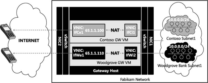
FIGURE 2-1 Separate gateway for each tenant.
Cloud bursting
Cloud bursting can be realized efficiently using HNV and Windows Server 2012 R2 gateway features. For example, Woodgrove Bank’s payroll application is a two-tier application consisting of a web front-end and SQL backend servers. Woodgrove Bank currently deploys five front-end servers to take care of their peak load during the start and end of the month. During non-peak days, these servers run at less than 20 percent of their capacity. To avoid wasting resources due to underutilization of these front-end servers during non-peak days, Woodgrove Bank would like to host just one front-end server on-premises and deploy an additional four front-end servers as VMs running on the Fabrikam network. Since Woodgrove Bank has to pay for the four front-end servers in the Fabrikam network only four or five days a month, they can save on the overall cost of deploying their payroll application.
Woodgrove Bank prefers to deploy their SQL backend servers on-premises due to the privacy and confidentiality of their data. But when the four web front-end servers are deployed on the Fabrikam network, they will need to securely access SQL data on Woodgrove Bank’s premises. To accomplish this, connectivity between Woodgrove Bank’s VMs on the Fabrikam network and the on-premises SQL servers will be provided by a site-to-site (S2S) virtual private network (VPN) tunnel. Site-to-site VPN allows Woodgrove Bank’s virtual network in Fabrikam to be seen as an extension of Woodgrove Bank’s on-premises network. This communication is enabled by S2S VPN between Woodgrove Bank’s edge network and the Fabrikam network. Fabrikam deploys an S2S VPN server at their cloud service provider’s edge network to enable Woodgrove Bank to connect from their premises networks to their virtual network in Fabrikam.
As shown in Figure 2-2, Fabrikam prefers deploying S2S VPN for multiple tenants on a shared gateway to bring down the cost of their gateway infrastructure. To simplify route configuration, Fabrikam deploys a single gateway for both NAT and S2S VPN.
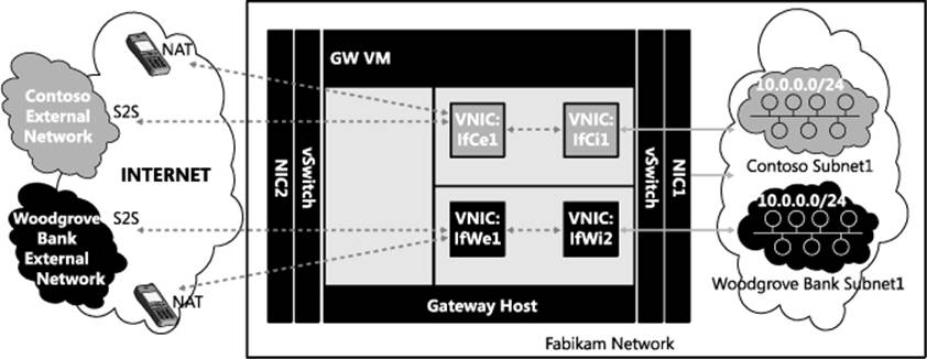
FIGURE 2-2 Gateway VM shared across multiple tunnels.
Cloud-based backup and recovery
Cloud services providers like Fabrikam can deploy cloud-based backup and recovery services for enterprises. For example, Contoso is a business with rented front office space in a commercial building. Contoso maintains their inventory management system on a single server in their office space. To ensure continued availability of the VMs that host their inventory system in the event of any disruption, Contoso replicates their VMs to the Fabrikam network using a technology like Hyper-V Replica in Windows Server 2012. Figure 2-3 shows how Fabrikam deploys their backup and recovery service using the same infrastructure used to deploy the cloud hosting and cloud bursting scenarios.
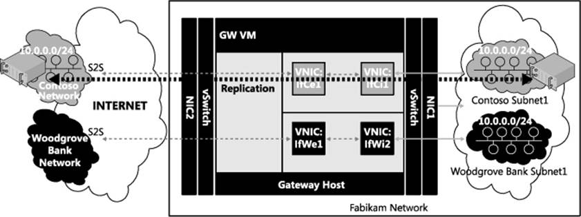
FIGURE 2-3 Shared gateway for shared services.
In this diagram, Contoso replicates business-critical VMs to the Fabrikam network. Replication traffic can then be sent to the Fabrikam network either over S2S VPN or directly over the Internet and be translated by NAT at the Fabrikam edge. In the event of unavailability of their office premises servers due to power or network failure, Contoso employees can access their VMs in the cloud service provider network using VPN. Fabrikam needs to provide such VPN services to all of their tenants, from those who bring in a single VM to those who bring in hundreds of VMs. Since multiple customers might bring in VMs with overlapping private IP addresses, the service provider deploys HNV for the same reasons mentioned earlier in the cloud bursting scenario: it is more cost-effective for Fabrikam to deploy a single VPN server to serve multiple customers with overlapping IP addresses than to deploy a separate VPN gateway for each customer. As shows in Figure 2-4, the new multi-tenancy capabilities of the Remote Access role services in Windows Server 2012 R2 helps cloud service providers to cost-effectively provide connectivity to VMs (in this case as part of cloud-based backup and recovery service) by enabling sharing of a gateway across multiple tenants.
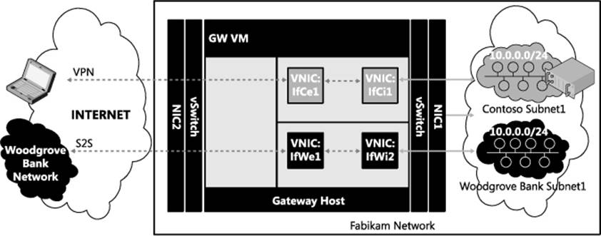
FIGURE 2-4 Single gateway from multiple services and multiple tenants.
HNV gateway
To provide connectivity from a tenant’s virtual network to any external network such as Intranet or Internet or a tenant’s corporate network, a gateway (GW) virtual machine is required. The gateway VM should generally have at least one interface connected to the virtual network and at least one more interface connected to the external network. For example, in Figure 2-5, a gateway VM dedicated to Contoso connects the Contoso virtual network in Fabrikam to external networks. Specifically, interface IfCi1 connects to the Contoso virtual network in Fabrikam while interface IfCe1 connects to the Contoso external network. When packets are routed from the Contoso external network to the Contoso subnet 10.0.0.0/24 on the Fabrikam network, they are forwarded to interface IfCe1. The TCP/IP stack on the gateway VM routes the packets to interface IfCi1, which delivers the packets inside the Contoso subnet 10.0.0.0/24. Similarly, when packets are routed from subnet 10.0.0.0/24 to the Contoso external networks, they are forwarded to interface IfCi1 and the TCP/IP stack on the GW VM routes the packets to interface IfCe1, which then delivers them to the Contoso external networks. Similarly, another gateway VM dedicated to Woodgrove Bank connects the Woodgrove Bank virtual network in Fabrikam to external networks.
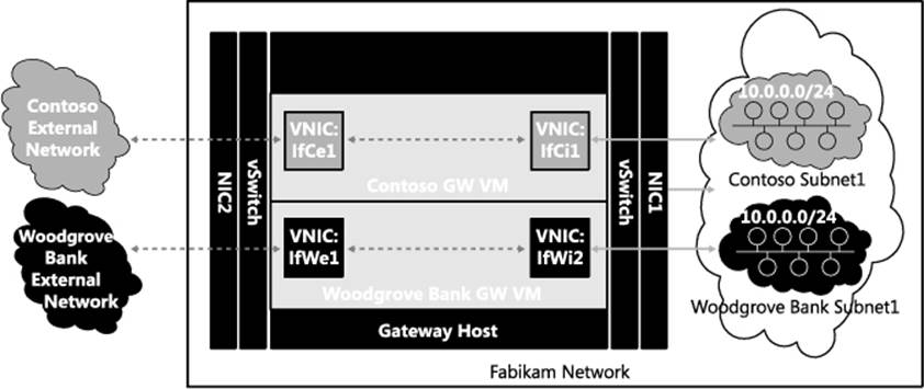
FIGURE 2-5 Gateway VM per tenant.
The problem with this approach is that the number of gateways increases linearly as the number of tenants grows. To ensure high availability, the cloud service provider would have to deploy two gateway VMs per tenant. Fabrikam would prefer deploying a gateway that could be shared across multiple tenants similar to deploying multiple tenant virtual networks over a shared physical network using HNV. In the sections that follow you will see how Fabrikam can reduce their gateway infrastructure costs by enabling isolation of routing and connectivity on a shared multi-tenant gateway using Windows Server 2012 R2.
Multi-tenant TCP/IP stack
With the new multi-tenant TCP/IP stack in Windows Server 2012 R2, a single VM can be used to route packets in a compartmentalized manner exclusively between tenants’ interfaces, for example between Contoso interfaces (IfCe1 and IfCi1) for Contoso traffic and between Woodgrove Bank interfaces (IfWe1 and IfWi1) for Woodgrove Bank traffic. This is made possible by creating separate routing compartments for Contoso and Woodgrove Bank. Routing compartments virtualize the TCP/IP stack to enable multiple routing entities with overlapping IP addresses to co-exist on the same gateway VM. Packets and network entities including interfaces, IP addresses, route tables, and ARP entries of each tenant are isolated by routing compartments. Interfaces and packets in one compartment cannot be seen in another compartment. Isolation of multi-tenant traffic when it enters or leaves the shared gateway VM is accomplished by extending the routing domain concept of HNV to the gateway VM. Windows Server 2012 R2 thus provides end-to-end network virtualization across all network layers of the TCP/IP stack above the physical layer.
Having a separate routing compartment per routing domain on a gateway VM enables connectivity between the virtual and external networks of multiple tenants. For example, in Figure 2-6 there are three compartments in the gateway VM (GW-VM) namely the Default (compartment id 1), Contoso, and Woodgrove Bank compartments. By default all network entities, such as interface If1, are created in compartment id 1, hence the name Default compartment. In this example, the interfaces IfCe1 and IfCi1 in the Contoso compartment are exclusive to Contoso, but their IP addresses and routes can overlap with the interfaces in any other tenant compartment. The multi-tenant TCP/IP stack in GW-VM routes packets between IfCi1 and IfCe1 as if only these two interfaces exist for the routing domain, which provides isolation for all Contoso packets. Interface IfCi1 connects the Contoso compartment in GW-VM to the Contoso virtual network on the Fabrikam network. As shown in the figure, the gateway runs as a VM and the host’s physical network interface card NIC1 is connected to the overlay network. So the packets of all tenants hit NIC1, and they are transmitted through interface IfCi1 to the Contoso compartment of the gateway VM by the Hyper-V virtual switch (vSwitch) connected to NIC1.
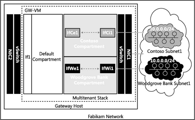
FIGURE 2-6 Multi-tenant gateway with compartment per tenant.
You can use Windows PowerShell to configure multi-tenancy, for example on GW-VM for Contoso. The following cmdlet enables multi-tenancy on NIC1:
Set-VmNetworkAdapterIsolation -VMName GW-VM -VMNetworkAdapterName NIC1
-MultiTenantStack on -IsolationMode NativeVirtualSubnet
To ensure that that all Network Virtualization using Generic Routing Encapsulation (NVGRE) packets in the Contoso routing domain are transmitted to the Contoso interface IfCi1, the following configuration step is required on the host:
Add-VmNetworkAdapterRoutingDomainMapping -VMName GW-VM -VMNetworkAdapterName NIC1
-RoutingDomainld "{12345678-1000-2000-3000-123456780001}" -RoutingDomainName "Contoso"
-IsolationId 6001 -IsolationName "IfCil"
After the above cmdlets are executed, a compartment for Contoso is created on GW-VM. This can be verified by executing the following cmdlets on GW-VM:
PS C:\> Get-NetCompartment
CompartmentId : 1
CompartmentDescription : Default Compartment
CompartmentGuid : {xxxxxxxx-xxxx-xxxx-xxxx-xxxxxxxxxxxx}
CompartmentId : 2
CompartmentDescription : Contoso
CompartmentGuid : {12345678-1000-2000-3000-123456780001}
The following cmdlet sets the IP address on interface IfCi1 to 10.0.254.2:
New-NetlpAddress -InterfaceAlias IfCil -AddressFamily IPv4 -Ipaddress 10.0.254.2
After this configuration, all packets in the Contoso virtual network that are forwarded to 10.0.254.2 are delivered to the Contoso compartment via interface IfCi1 by the vSwitch on the gateway host. Since interface IfCi1 is created in the Contoso compartment, these packets can be routed to any other interface, such as IfCe1, in the same compartment. In a similar configuration for the other tenant Woodgrove Bank, the interface IfWi1 would be created in the Woodgrove Bank compartment with the same IP address, 10.0.254.2. The traffic for the Contoso routing domain will then be injected into the Contoso compartment in the gateway VM via interface IfCi1, and the traffic of the Woodgrove Bank routing domain will be injected into the Woodgrove Bank compartment in the gateway VM via interface IfWi1.
Packets in the Woodgrove Bank compartment can be routed over S2S VPN to the premises of Woodgrove Bank or to the devices of Woodgrove Bank employees via remote access VPN to the Internet through NAT. Compartments also enable routing between virtual and physical networks using the forwarding gateway feature in Windows Server 2012 R2.
Border Gateway Protocol (BGP) can also be enabled on interfaces IfCi1 and IfWi1 using Windows Server 2012 R2 Routing and Remote Access Service (RRAS) even though they have same IP address. There are two BGP listeners on port 179 with the same IP address, 10.0.254.2, in two different compartments on GW-VM. The two listeners can learn overlapping routes (e.g., 10.1.1.0/24) from their respective peers using multi-tenant routing in Windows Server 2012 R2.
Multi-tenant S2S VPN gateway
Windows Server 2012 R2 can provide two modes of VPN connectivity:
![]() Site-to-site (S2S) VPN tunnels between tenant sites and tenant virtual networks
Site-to-site (S2S) VPN tunnels between tenant sites and tenant virtual networks
![]() Remote access VPN tunnels from devices on the Internet to tenant virtual networks
Remote access VPN tunnels from devices on the Internet to tenant virtual networks
For example, S2S VPN connectivity can be enabled from the office sites of Woodgrove Bank and Contoso to their respective virtual networks using a single Windows Server 2012 R2 gateway VM named GW-VM. Figure 2-7 depicts a deployment with two tenants, Woodgrove Bank and Contoso, connected to their respective virtual networks over S2S VPN from their premises. Woodgrove Bank has two sites, one each in New York (NY) and San Francisco (SFO), with internal subnets 10.1.0.0/24 and 10.2.0.0/24, respectively. From both of these sites, Woodgrove Bank connects to its virtual network 10.0.0.0/24 in Fabrikam through GW-VM via S2S VPN. Contoso connects its internal network 10.1.0.0/24 in New York to its virtual network 10.0.0.0/24 in Fabrikam through the same GW-VM via S2S VPN. Both tenants dial to the same interface If2 (public IP address 131.107.10.10), which is on the Internet.

FIGURE 2-7 Multi-tenant S2S VPN.
To enable multi-tenancy for remote access on GW-VM and to enable S2S VPN for the Contoso and Woodgrove Bank tenants, the following cmdlets need to be executed on GW-VM:
Add-WindowsFeature -Name Remote Access -IncludeAllSubFeature
-IncludeManagementTools
Install-Remote Access -MultiTenancy
Enable-Remote AccessRoutingDomain -Name Woodgrove -Type All
Enable-Remote AccessRoutingDomain -Name Contoso -Type All
To enable S2S connectivity from the NY and SFO sites of Woodgrove Bank, the S2S VPN interfaces IfWe1 and IfWe2 can be configured using the following two cmdlets. Note that the RoutingDomain parameter defines the association between the tenant and the S2S VPN interface:
Add-VpnS2SInterface -RoutingDomain Woodgrove -Name IfWel
-Destination 59.10.10.100 -Protocol IKEv2 -AuthenticationMethod PSKOnly
-SharedSecret abc -IPv4Subnet 10.1.0.0/24:100 -SourceIpAddress 131.107.10.10
Add-VpnS2SInterface -RoutingDomain Woodgrove -Name IfWe2
-Destination 60.10.10.100 -Protocol IKEv2 -AuthenticationMethod PSKOnly
-SharedSecret abc -IPv4Subnet 10.2.0.0/24:100 -SourceIpAddress 131.107.10.10
The following cmdlet configures the S2S VPN interface on GW-VM for tenant Contoso to connect from the NY site:
Add-VpnS2SInterface -RoutingDomain Contoso -Name IfCel -Destination 59.10.10.10
-Protocol IKEv2 -AuthenticationMethod PSKOnly -SharedSecret abc
-IPv4Subnet 10.1.0.0/24:100 -Sourcelpddress 131.107.10.10
The previous series of cmdlets configure the S2S VPN virtual interfaces IfWe1, IfWe2, and IfCe1 on the gateway. These virtual interfaces are created in the Contoso or Woodgrove Bank compartment only after tunnel establishment.
Examining the lifecycle of the S2S VPN interface IfCe1 can help you better understand how the multi-tenancy of S2S VPN works. When the S2S VPN interface IfCe1 is configured using the above cmdlet, the Windows Server 2012 R2 Remote Access service plumbs the necessary IPsec policies on GW-VM to allow IPsec/IKEv2 (Internet Key Exchange version 2) tunnel connection from 59.10.10.10 to interface If1 (131.107.10.10) on GW-VM. Similarly, when IfWe1 and IfWe2 are configured, IPsec policies are plumbed to allow IPsec/IKEv2 tunnels from 59.10.10.100 and 60.10.10.100 to interface If1 (131.107.10.10) on GW-VM.
When an IPsec/IKEv2 S2S VPN connection is dialed from 59.10.10.10 to 131.107.10.10 (the IP address of interface If2 in GW-VM), it matches the IPsec policy configured for the S2S VPN interface IfCe1 on GW-VM. After IKE pre-shared key (PSK) authentication, the Remote Access service on GW-VM searches the list of S2S interfaces to find one with the matching destination IP address 59.10.10.10 and finds interface IfCe1. When the interface IfCe1 is identified, it is created in the Contoso compartment based on the RoutingDomain value for Contoso in the interface IfCe1 configuration. This is how the tenant is identified for an incoming S2S connection with PSK authentication.
After interface IfCe1 is created in the Contoso compartment in addition to the already existing interface IfCi1 (note that interface IfCi1 connects GW-VM to the virtual network of Contoso), packets can be routed between interfaces IfCi1 and IfCe1. The S2S interface IfCe1 connects the Contoso NY site to the gateway. Thus the Contoso virtual network in Fabrikam is connected over S2S VPN to Contoso NY site via S2S VPN. If the S2S interface IfCe1 is dialed out from the gateway, the Remote Access service creates interface IfCe1 in the Contoso compartment based on the RoutingDomain value of IfCe1 configuration.
Similarly, the S2S interfaces IfWe1 and IfWe2 are created in the Woodgrove Bank compartment, enabling the routing of packets between the Woodgrove Bank virtual network and the Woodgrove Bank sites in NY and SFO through interfaces IfWe1 and IfWe2, respectively. Thus the routing of packets between multiple tenants’ sites and their respective virtual networks in Fabrikam is enabled on a shared multi-tenant S2S VPN gateway.
Authentication of S2S VPN
Authentication plays a key role in identifying the S2S interface for an incoming connection and for the subsequent determination of the compartment or tenant. S2S VPN connections on Fabrikam GW-VM can be authenticated using one of the following methods
![]() Pre-Shared Key (PSK)
Pre-Shared Key (PSK)
![]() X.501 Certificates
X.501 Certificates
![]() Extensible Authentication Protocol (EAP)
Extensible Authentication Protocol (EAP)
When an S2S VPN interface is dialed from the server, it is called an initiator; when the server accepts an incoming connection, it is called a responder. IKE/IPsec polices for S2S VPN can be specified at the server (gateway) level or at the interface level.
For outgoing connections (initiator), the gateway uses policies and parameters specified at the interface level. For non-PSK based authentication, interface level IPsec policies are plumbed only while dialing out the connection. In the case of PSK-based authentication, the IPsec policies corresponding to the S2S interface become effective immediately after configuration.
For incoming connections (responder), the gateway has a list of interfaces and needs to activate (create a tunnel for) a specific interface by registering with the TCP/IP stack. It can determine the specific interface for which the connection is being requested only after authentication. Hence the basis on which an incoming connection is identified is based on the authentication method.
If the authentication method is username, the S2S interface is identified based on the username that is being authenticated, and the S2S interface whose name matches the authenticated username is activated. If there is no matching S2S interface name, the incoming connection is treated as a remote access (dial-in) VPN connection.
If the authentication method is certificates, then the S2S interface is identified based on the subject name of the certificate being authenticated. The S2S interface whose name matches the certificate subject name is then activated (see http://technet.microsoft.com/en-US/library/dd469750.aspx).
If the authentication method is PSK, the S2S interface is identified based on the source IP address of the incoming IKE packets and is matched with the destination IP address of the configured S2S interfaces.
Since authentication in IKE happens after initial IPsec negotiation is complete, all incoming connections are governed by server level policies except for PSK-based authentication. In the case of PSK-based authentication, since identification of the tunnel is based on IP address, only one interface can be enabled per destination, and the initiator and responder policies are governed by S2S interface level policies. Also, if the authentication method is PSK, only IPv4 or IPv6 addresses can be specified as the destination. For other authentication methods, any resolvable name can be specified as the destination of the S2S interface.
MORE INFO Detailed steps for configuring S2S VPN using pre-shared key authentication are outlined at http://technet.microsoft.com/en-us/library/jj574210.aspx. If X.501 certificates are used to authenticate S2S connections, all the incoming connections must chain up to the root certificate of Fabrikam. Detailed steps for using X.501 certificates for authenticating S2S VPN connections are outlined at http://technet.microsoft.com/en-us/library/jj574149.aspx. S2S connections can also be authenticated using Extensible Authentication Protocol. Please refer to http://technet.microsoft.com/en-us/library/jj574129.aspx for details on using EAP for S2S VPN authentication.
Routing packets over S2S VPN interfaces
For connectivity to be established between applications in the customer site and the virtual network in the service provider network, it is important to have proper routes configured across S2S VPN tunnels. The following options are available to configure routes:
![]() Static routes
Static routes
![]() Border Gateway Protocol (BGP)
Border Gateway Protocol (BGP)
Static routes
Static routes can be configured on S2S interfaces so that when packets arrive in the compartment of the tenant, they are routed over a specific S2S interface. In the Woodgrove Bank example, the routes 10.1.0.0/24 and 10.2.0.0/24 are added on the S2S interfaces IfWe1 and IfWe2, respectively, with a metric of 100. These routes trigger the S2S connection to be dialed (if it is disconnected) when packets that match the routes on the S2S interface end up in the Woodgrove Bank compartment. There is also a provision to add routes on an S2S interface only after the connection is established without triggering the connection by specifying “PostConnectionIPv4Subnet” using the following cmdlet:
Set-VpnS2SInterface -RoutingDomain Contoso -Name IfCl
-PostConnectionIPv4Subnet 10.1.0.0/24:100
Route exchange via BGP
Routes can be exchanged between customer site gateways and the customer virtual network in the cloud service provider over S2S VPN via BGP. Details of BGP configuration and various topologies are described later in the section titled “Routing between virtual networks and tenant sites.”
For BGP connection establishment, host-specific routes (/32 in the case of IPv4 and /128 in the case of IPv6) of the BGP peer are added as trigger routes on the S2S VPN interface. This ensures that when BGP connection establishment is attempted, the S2S connection is dialed and the routes of the BGP peers are added on the S2S interface so that BGP packets can be tunneled over the S2S interface. Once BGP peering is established, the rest of the routes are exchanged by BGP peers running at either end.
In the Woodgrove Bank example, the BGP peer can be configured on interface IfWe1, IfWe2, or IfWi1. Since interface IfWi1 is always present and has a fixed IP address, it is recommended to configure BGP on IfWi1, which connects to the virtual network. Once BGP on IfWi1 establishes a connection with BGP peers in the NY and SFO sites, the routes 10.1.0.0/24 and 10.2.0.0/24 are learned and plumbed on the S2S interfaces IfWe2 and IfWi1, respectively, and no manual configuration of routes on S2S interfaces is needed.
Rate limiting of traffic on an S2S VPN interface
Data processing of S2S tunnels is compute-intensive because of the encryption and decryption that occurs. With a multi-tenant gateway, the same VM is used to serve multiple S2S tunnels of multiple tenants. Hence, if the rate at which each tunnel can send or receive data is not controlled, it is possible for the data of one tunnel to consume all available resources on the gateway, thus starving the other tunnels. It is therefore recommended that you rate-limit traffic on each S2S tunnel. The following cmdlet is an example where bandwidth is limited to 1,024 kilobits per second (kbps) in each direction:
Set-VpnS2SInterface -RoutingDomain Contoso -Name If2 -TxBandwidthKbps 1024
-RxBandwidthKbps 1024
By default, all connections are created with a 5,120 kbps limit in each direction so that no single tunnel hogs the CPU.
Static IP filtering on an S2S VPN interface
On each of the S2S interfaces, static IP filters can be configured to allow or block packets based on the source IP address, destination IP address, source port, destination port, and protocol in each direction. You can set packet filters per interface and configure them to do one of the following:
![]() Pass through all traffic except packets prohibited by specified filters
Pass through all traffic except packets prohibited by specified filters
![]() Discard all traffic except packets allowed by specified filters
Discard all traffic except packets allowed by specified filters
For example, Contoso could limit traffic going out of the virtual network by adding outbound filters like this:
Add-Remote AccessIpFilter -InterfaceAlias IfCil -Action Deny -Direction Outbound
-AddressFamily IPv4 -List @("10.0.0.0/24:10.1.0.0/24:any","any:any:ICMP:0:0")
After configuring filters using the previous cmdlet, all outgoing packets through interface IfCi1 are dropped except for those that match the following conditions:
![]() Source IP subnet is 10.0.0.0/24 and destination IP subnet is 10.1.0.0/24
Source IP subnet is 10.0.0.0/24 and destination IP subnet is 10.1.0.0/24
![]() Any ICMP traffic
Any ICMP traffic
Contoso could also restrict incoming traffic into the virtual subnet 10.0.0.0/16 to SSL (TCP port 443) and Ping (IMCP request code 8) traffic using the following cmdlet:
Add-Remote AccessIpFilter -InterfaceAlias IfCil -Action Deny -Direction Inbound
-AddressFamily IPv4 -List <a("any:10.0.0.0/16:TCP:0:443"," any:any:ICMP:8:0")
As a final example, the following cmdlet allows all outgoing traffic through interface IfCi1 except TCP traffic from IP subnet 10.0.0.0/16 to 10.2.0.0/16 with source port 1234 and destination port 4321:
Add-Remote AccessIpFilter -InterfaceAlias IfCil -Action Allow
-List @("10.0.0.0/16:10.2.0.0/16:TCP:1234:4321") -Direction Outbound
-AddressFamily IPv4
Multi-tenant Remote Access VPN gateway
Hybrid networking enables the enterprise or small- to medium-sized business (SMB) to deploy their workloads in the cloud by hosting them in a cloud service provider’s datacenter. The workloads can then be accessed from inside the corporate network via an S2S VPN. When employees need to access these workloads from outside the corporate network, they can connect to their corporate network via their VPN gateway and access the workloads via S2S VPN. If the VPN gateway is not available for some reason, the employees can still access the workloads by directly establishing a VPN connection with the cloud service provider’s gateway.
Businesses that do not have their own remote access (dial-in) VPN infrastructure can allow their employees to connect via VPN to the cloud service provider’s gateway and access workloads in the cloud or on the business premises via S2S VPN. Employees of businesses without infrastructure that have their entire workloads running in the cloud need to connect via VPN to the cloud service provider’s gateway to access their internal workloads.
NOTE “Access the workloads” means using client applications like SQL client for querying a database server. Cloud service providers can also allow administrators to have access to the actual VMs for diagnostic and management purposes via Remote Desktop Protocol or similar mechanisms.
The remote access (dial-in) VPN requirements for Woodgrove Bank and Contoso, Ltd. can be fulfilled by the cloud service provider Fabrikam by using the multi-tenancy capability of the Windows Server 2012 R2 Remote Access role. In Figure 2-8, a gateway VM dedicated to Contoso enables VPN connections from employees of Contoso so they can connect to the Contoso virtual network in Fabrikam. Interface IfCi1 connects to the Contoso virtual network in Fabrikam while the VPN clients connect over interface IfCe1. After a VPN connection has been established, packets to the Contoso virtual subnet 10.0.0.0/24 are sent to the Contoso GW VM on the Fabrikam network. The TCP/IP stack on the GW VM routes the packets to interface IfCi1, which then delivers the packets inside the Contoso subnet 10.0.0.0/24. In the opposite direction, when packets are routed from subnet 10.0.0.0/24 to a VPN client, they are forwarded to interface IfCi1, and the TCP/IP stack on GW VM routes the packets over a VPN tunnel via interface IfCe1. Similarly, another GW VM dedicated for Woodgrove Bank enables VPN clients to connect to the Woodgrove Bank virtual network in Fabrikam.
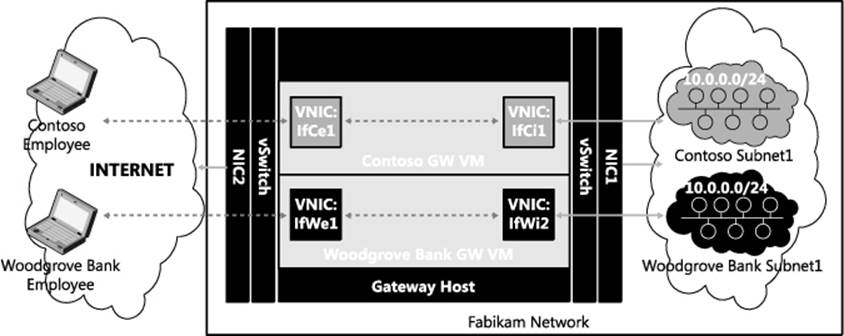
FIGURE 2-8 Separate gateway VM per tenant.
There are two problems with this approach:
![]() The number of gateways increases linearly as the number of tenants grows, and for high availability, the cloud service provider would have to deploy two gateway VMs per tenant.
The number of gateways increases linearly as the number of tenants grows, and for high availability, the cloud service provider would have to deploy two gateway VMs per tenant.
![]() Each tenant requires at least one public IP address on the public interface of the GW VM. If multiple tenant gateways are deployed behind a NAT device that has only one public IP, the destination port to which the tenants connect should be different for different tenants. As a result, VPN tunnels that rely on SSL port 443 cannot be used by the tenants. If the port changes to some other random port, the packets may be dropped by firewalls in coffee shops or other access points from which tenants connect (the very reason why port 443 is used for Secure Socket Tunneling Protocol (SSTP) so that it can traverse firewalls).
Each tenant requires at least one public IP address on the public interface of the GW VM. If multiple tenant gateways are deployed behind a NAT device that has only one public IP, the destination port to which the tenants connect should be different for different tenants. As a result, VPN tunnels that rely on SSL port 443 cannot be used by the tenants. If the port changes to some other random port, the packets may be dropped by firewalls in coffee shops or other access points from which tenants connect (the very reason why port 443 is used for Secure Socket Tunneling Protocol (SSTP) so that it can traverse firewalls).
Fabrikam would prefer deploying a gateway that could be shared across multiple tenants similar to deploying multiple tenant virtual networks over a shared physical network using HVN. Figure 2-9 depicts a deployment where employees of two tenants, Woodgrove Bank and Contoso, connect to their respective virtual networks over a VPN from the Internet. Note that the VPN connections for both tenants dial to the same interface If2 (IP address 131.107.10.10), which is connected to Internet.
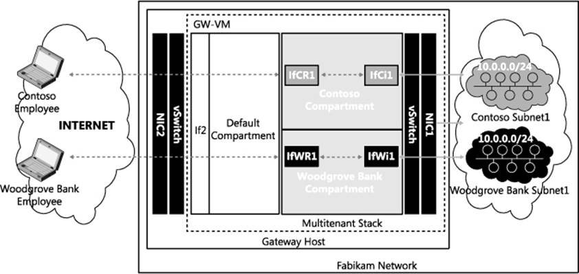
FIGURE 2-9 Multi-tenant remote access VPN.
Before examining how this multi-tenant VPN works, you must first understand in detail how Remote Access VPN works. When the first VPN client of a tenant dials in to the public interface of the VPN server, a new “RAS dial-in interface” is created on the VPN server. After connecting to the VPN server, the VPN client is assigned an IP address from the address pool configured on the VPN server. The traffic to and from the IP addresses in this pool is routable on the internal network and allows the VPN client to access resources behind the VPN server. For each VPN client, a sub-interface is created on the RAS dial-in interface and a /32 route with the IP address assigned to the VPN client is added on the sub-interface. The IP address assigned to the client identifies the specific sub-interface on which data is routed to a specific VPN client.
As explained in the section titled “Multi-tenant TCP/IP stack” earlier in this chapter, each compartment in the multi-tenant GW-VM isolates the traffic meant for each routing domain. So when a Contoso employee dials a VPN connection to the public interface of the cloud service provider’s gateway VPN server, the multi-tenant aware Remote Access VPN server validates the user’s credentials and identifies the corresponding tenant. It then creates a new sub-interface of the RAS dial-in interface in the Contoso compartment and assigns the client an IP address as configured in the Contoso compartment’s routing domain. A VPN tunnel is then created between the client and the newly created RAS dial-in interface in the Contoso compartment.
When the RAS dial-in interface and the VPN tunnel have been created, the data packets received from the VPN client end up in the Contoso compartment. Inside the Contoso compartment, packets are routed based on their destination IP address in the usual way. If the destination address is part of the Contoso virtual network 10.0.0.0/24, the packets are forwarded to the Contoso virtual network using the VSID associated with Contoso. Similarly, when traffic in the opposite direction meant for the client reaches the internal vSwitch of Fabrikam’s cloud gateway, it injects the packets in the Contoso compartment based on VSID. Once a packet lands in the Contoso compartment, the /32 route on the dial-in interface causes the packet to be routed on the dial-in interface that delivers packets to the corresponding VPN tunnel.
Authentication of VPN clients
Since a single multi-tenant VPN gateway can be used by the cloud service provider for multiple tenants, the gateway has to authenticate incoming VPN connections as well as identify the tenant. The Remote Access VPN server supports two modes of tenant identification.
![]() Tenant identification based on username
Tenant identification based on username
![]() Tenant identification based on RADIUS ClassID attribute
Tenant identification based on RADIUS ClassID attribute
The tenant to which an incoming VPN connection belongs is identified by the VPN server based on the credentials, and when authentication is complete, the tunnel is created in the identified tenant compartment.
Tenant identification based on username
In this approach, the tenant is identified based on the username in the credentials the VPN client supplies as part of the authentication process. For this to work, the Tenant Name parameter has to be configured per routing domain on the multi-tenant VPN gateway. Tenant Name can be any user-defined name or regular expression (e.g., “Contoso” or “*Contoso*”) to identify the tenant and routing domain, but it has to be unique across routing domains on a given multi-tenant VPN server.
The Set-RemoteAccessRoutingDomain Windows PowerShell cmdlet can be used to configure the Tenant Name parameter as follows:
Set-RemoteAccessRoutingDomain -Name "Contoso" -TenantName ".*Contoso.*"
Set-RemoteAccessRoutingDomain -Name "Woodgrove" -TenantName ".*Woodgrove.*"
For example, an employee John Doe from Contoso, Ltd. can dial a VPN connection using one of the following values for username: JohnDoe@Contoso.Fabrikam.com or Contoso\JohnDoe. On parsing this username, the multi-tenant VPN server tries to match the “Contoso” string with the configured set of tenant names on the server. If there is a match, the server creates the VPN tunnel in the RoutingDomain compartment of the associated TenantName after authentication. In this example, the associated RoutingDomain is Contoso.
Actual authentication of VPN clients for all of the tenants can be done by the VPN server or by a remote RADIUS server. Where authentication is done by the VPN server, Fabrikam should deploy the necessary authentication infrastructure so VPN clients of all tenants can be authenticated by the server. Fabrikam could implement such an authentication infrastructure as follows:
1. Fabrikam deploys a domain controller for the Fabrikam parent domain.
2. Fabrikam deploys two domain controllers for the child domains Contoso and Woodgrove Bank.
3. The multi-tenant VPN server is joined to the Fabrikam domain.
Where authentication is performed by a RADIUS server, the VPN server needs to have a RADIUS server configured for client authentication. This can be done by using an external server as RADIUS or by configuring the Windows Network Policy Server role on the VPN server (seehttp://technet.microsoft.com/en-us/library/cc731108.aspx).
Tenant identification based on the RADIUS ClassId attribute
Another tenant identification option available is using the RADIUS class attribute (see http://technet.microsoft.com/en-us/library/dd197472(v=ws.10).aspx) to identify the tenant. In this approach, the VPN server relies on a RADIUS server to complete the authentication and return the tenant information using the RADIUS ClassID (value 25) attribute. The RADIUS server must be configured to return the ClassId attribute in the format “TenantName=<string>” where <string> should be replaced with the value of TenantName as configured using the Set-RemoteAccessRoutingDomain cmdlet.
For example, Fabrikam could assign the following usernames to its tenants:
![]() JoeWoodgrove@Fabrikam.com or Fabrikam\JoeWoodgrove
JoeWoodgrove@Fabrikam.com or Fabrikam\JoeWoodgrove
![]() JoeContoso@Fabrikam.com or Fabrikam\JoeContoso
JoeContoso@Fabrikam.com or Fabrikam\JoeContoso
Fabrikam would then configure its RADIUS policies such that if the username has substring Woodgrove, the class attribute returned would be “TenantName=Woodgrove” while if the username it has substring Contoso, the class attribute returned would be “TenantName=Contoso.” This approach gives Fabrikam flexibility in deploying its authentication servers and username combinations for its tenants’ VPN clients.
When authentication is completed, the VPN client endpoint needs to be assigned an IPv4 address or IPv6 address. One of the following parameters therefore needs to be configured for every RoutingDomain on the remote access VPN server in a multi-tenant deployment:
![]() A valid IPv4 address range for the IP addresses to be assigned to VPN clients
A valid IPv4 address range for the IP addresses to be assigned to VPN clients
![]() A valid IPv6 address prefix representing the pool of IP addresses to be assigned to VPN clients
A valid IPv6 address prefix representing the pool of IP addresses to be assigned to VPN clients
As an example, the following cmdlets configure the same IPv4 and IPv6 address range for the Contoso and Woodgrove Bank tenants and cap the aggregate bandwidth of all VPN clients to 5,120 kbps:
Set-Remote AccessRoutingDomain -Name Contoso -IPAddressRange 11.11.11.1, 11.11.11.200
-IPv6Prefix 2001:db8:a::/64 -EnableQoS Enabled -TxBandwidthKbps 5120
-RxBandwidthKbps 5120
Set-Remote AccessRoutingDomain -Name Woodgrove -IPAddressRange 11.11.11.1, 11.11.11.200
-IPv6Prefix 2001:db8:a::/64 -EnableQoS Enabled -TxBandwidthKbps 5120
-RxBandwidthKbps 5120
Note that the multi-tenancy of the remote access VPN server enables two clients of different tenants to be assigned the same IP address.
Routing between virtual networks and tenant sites
Border Gateway Protocol (BGP) can enable cloud service provider Fabrikam to manage routing between the virtual networks hosted in Fabrikam of the organizations Woodgrove Bank and Contoso, Ltd and the respective on-premises networks of these organizations. Figure 2-10, which reproduces Figure 2-7 from earlier in this chapter, depicts a deployment with two tenants, Woodgrove Bank and Contoso, connecting to their respective virtual networks over S2S VPN from their premises. Woodgrove Bank has two sites, one each in New York (NY) and San Francisco (SFO), with internal subnets 10.1.0.0/24 and 10.2.0.0/24 respectively. From both of these sites, Woodgrove Bank connects to its virtual network 10.0.0.0/24 in Fabrikam through a Windows Server 2012 R2 VM named GW-VM via S2S VPN. Contoso connects its internal network 10.1.0.0/24 in New York to its virtual network 10.0.0.0/24 in Fabrikam through the same GW-VM via S2S VPN.
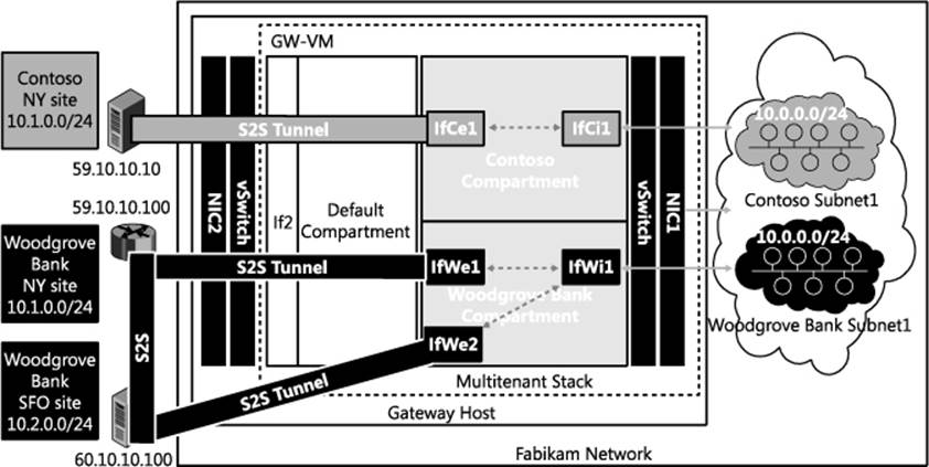
FIGURE 2-10 Connectivity between virtual networks and tenant sites.
To consider routing between the Woodgrove Bank virtual network and its SFO and NY sites, the following routes need to be configured in the Woodgrove Bank compartment:
![]() On interface IfWi1: 10.0.0.0/24
On interface IfWi1: 10.0.0.0/24
![]() On interface IfWe1: 10.1.0.0/24
On interface IfWe1: 10.1.0.0/24
![]() On interface IfWe2: 10.2.0.0/24
On interface IfWe2: 10.2.0.0/24
Whenever a new subnet (for example 10.3.0.0/24) is added in the NY site, the corresponding new route needs to be added on interface IfWe1 so that packets from the Woodgrove Bank virtual network can reach the NY site.
With the above specified routes, if the S2S VPN tunnel between the NY site and Fabrikam goes down, traffic cannot be sent to the NY site. There is a link between the NY and SFO sites, however, so traffic to the NY site could still be routed over SFO. This means route 10.1.0.0/24 needs to be added on interface IfWe2. When the S2S VPN tunnel between NY and Fabrikam is restored, traffic to NY will be split across two paths: directly to NY and via SFO. To restore routing so it uses the best path, the route 10.1.0.0/24 on IfWe2 needs to be removed after the tunnel between SFO and Fabrikam has been restored.
Adding and removing routes based on tunnel states like this requires manual intervention and results in sub-optimal routing that can lead to connectivity loss. One way to solve this problem is via route metrics (see http://support.microsoft.com/kb/140859 for some background information on route metrics). The following routes with appropriate route metrics will solve the problem in this example:
![]() On interface IfWe1:
On interface IfWe1:
• Route 10.1.0.0/24 with metric 100
• Route 10.2.0.0/24 with metric 200
![]() On interface IfWe2:
On interface IfWe2:
• Route 10.1.0.0/24 with metric 200
• Route 10.2.0.0/24 with metric 100
With the above routes and route metrics configured, traffic to the NY site is normally routed over interface IfWe1 since the metric of route 10.1.0.0/24 is lower on interface IfWe1. Similarly, traffic to SFO is normally routed over interface IfWe2 since the metric of route 10.2.0.0/24 is lower on interface IfWe2. When the tunnel between the NY site and Fabrikam goes down, the S2S VPN interface IfWe1 also goes down and traffic to the NY site is routed over interface IfWe2 due to route 10.1.0.0/24 with metric 200. When the SFO tunnel is restored, interface IfWe1 comes back up along with route 10.1.0.0/24 with metric 100, optimally routing traffic to the NY site over interface IfWe1 again.
While static routes with metrics can work for a small set of sites and routes, the combination of sites, interfaces, and metrics quickly becomes unmanageable as the number of sites and routes increases. Clearly, as the number of customers (tenants) and their sites increases, the task of manually managing cloud service provider routes and ever-changing on-premises network routes becomes impossible. Similarly, on the enterprise side, keeping up-to-date route information for all of the subnets hosted in the cloud is a challenge in itself. This is where dynamic routing using a multi-tenant capable BGP router can ease manageability as well as provide faster convergence. The next section illustrates the concepts involved in detail.
Dynamic routing with BGP
With a dynamic routing protocol, routes can be exchanged between peers, obviating the need for adding static routes on each node along a path. Considering the Woodgrove Bank and Contoso scenario again, dynamic routing can play a role in enabling communication between an enterprise subnet and virtual networks in a cloud service provider.
Figure 2-11 shows the details of the interfaces on the edge routers in the NY and SFO sites. Interface IfNi1 is connected to subnet 10.1.0.0/24. An S2S VPN tunnel is established between interfaces IfFe1 on the SFO router to IfWe1 in the Woodgrove Bank compartment on the multi-tenant gateway GW-VM.
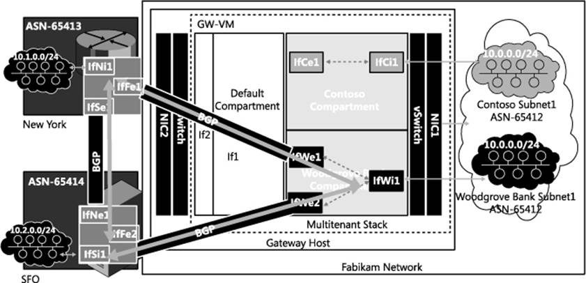
FIGURE 2-11 BGP routing and interface details.
If a dynamic routing protocol is configured between the router in NY and the router in the Woodgrove Bank compartment of GW-VM, then the route 10.0.0.0/24 on interface IfWi1 is propagated to the routing peer listening on the NY router, and the routing protocol adds the route 10.0.0.0/24 on interface IfFe1. Similarly, the route 10.1.0.0/24 is added on the interface IfWe1 in the Woodgrove Bank compartment on the multi-tenant gateway. The only manual configuration required for route exchanges is the configuration of the information required for the operation of the routing protocol. When this is done, routes are learned dynamically with no need for any manual intervention.
The rest of this section focuses on how one such routing protocol (BGP) can be used for dynamic route learning. For more information on BGP, see http://www.bgp4.as
Examine in more detail the interfaces and routes shown in Figure 2-11. The router in the NY edge network has three interfaces of relevance:
![]() Interface IfNi1 (with IP address 10.1.0.1) connects to subnet 10.1.0.0/24.
Interface IfNi1 (with IP address 10.1.0.1) connects to subnet 10.1.0.0/24.
![]() Interface IfSe1 connects to the SFO site via S2S VPN.
Interface IfSe1 connects to the SFO site via S2S VPN.
![]() Interface IfFe1 connects to the Woodgrove Bank virtual network 10.0.0.0/24 via S2S VPN.
Interface IfFe1 connects to the Woodgrove Bank virtual network 10.0.0.0/24 via S2S VPN.
Similarly, the router in the SFO edge network has three interfaces of relevance:
![]() Interface IfSi1 (with IP address 10.2.0.1) connects to subnet 10.2.0.0/24.
Interface IfSi1 (with IP address 10.2.0.1) connects to subnet 10.2.0.0/24.
![]() Interface IfNe1 connects to the NY site via S2S VPN.
Interface IfNe1 connects to the NY site via S2S VPN.
![]() Interface IfFe2 connects to the Woodgrove Bank virtual network 10.0.0.0/24 via S2S VPN.
Interface IfFe2 connects to the Woodgrove Bank virtual network 10.0.0.0/24 via S2S VPN.
In the Woodgrove Bank compartment on the multi-tenant gateway, there are three interfaces of relevance:
![]() Interface IfWi1 (with IP address 10.0.254.2) connects to the virtual network 10.0.0.0/24.
Interface IfWi1 (with IP address 10.0.254.2) connects to the virtual network 10.0.0.0/24.
![]() Interface IfWe1 connects to the NY site via S2S VPN.
Interface IfWe1 connects to the NY site via S2S VPN.
![]() Interface IfWe2 connects to the SFO site via S2S VPN.
Interface IfWe2 connects to the SFO site via S2S VPN.
While BGP can be enabled on all interfaces, in this example BGP is enabled only on interface IfWi1 in the Woodgrove Bank compartment, interface ifSi1 in the SFO site, and interface ifNi1 in the NY site. BGP uses the concept of autonomous system (AS) and AS number (ASN) for making routing decisions. This example assumes that each site is identified by a unique ASN in the private range 64512 to 65535. The subnet on the Fabrikam network will be identified by ASN 65412, and the NY and SFO sites will be assigned ASNs of 65413 and 65414, respectively.
The following cmdlet enables BGP in the Woodgrove Bank compartment with ASN 65412 and uses the IPv4 address of interface IfWi1 as the BGP identifier:
# Add a BGP Router for Woodgrove Tenant on the Cloud Service provider Gateway
Add-BgpRouter -RoutingDomain Woodgrove -Bgpldentifier 10.0.254.2 -LocalASN 65412
The next step is to enable BGP peering for the NY and SFO sites:
# Add a BGP Peer for New York site of Woodgrove tenant
Add-BgpPeer -RoutingDomain Woodgrove -Name NY -LocalIPAddress 10.0.254.2
-PeerIPAddress 10.1.0.1 -PeerASN 65413 -LocalASN 65412 -OperationMode Mixed
-PeeringMode Automatic
# Add a BGP Peer for SFO site of Woodgrove tenant
Add-BgpPeer -RoutingDomain Woodgrove -Name SFO -LocalIPAddress 10.0.254.2
-PeerIPAddress 10.2.0.1 -PeerASN 65414 -LocalASN 65412 -OperationMode Mixed
-PeeringMode Automatic
With the previous cmdlets, BGP running in the Woodgrove Bank compartment uses the local IP address 10.0.254.2 and the ASN 65412 to peer with BGP in the NY and SFO sites with IP 10.1.0.1/ASN 65413 and IP 10.2.0.1/ASN 65414, respectively. With this configuration, BGP operates in a mode where it can initiate connections to peers as well as receive connections from peers automatically (this is the default mode of operation for the Windows BGP router). After similar configuration on the edge devices in the NY and SFO sites of Woodgrove Bank, the BGP peering configuration is completed.
NOTE The edge devices in the NY and SFO sites can be third-party routers. In that case, the configuration of these devices will vary from vendor to vendor.
BGP peering to the NY site can be established only if an S2S VPN connection to IfWe1 is established. To trigger S2S VPN connections to IfWe1, a host-specific route for the remote BGP peer is added on the S2S VPN interface IfWe1 with the following cmdlet:
# Add a BGP triggering route in the VPN S2S Interface for Woodgrove tenant
Set-VpnS2SInterface -Name IfWel -IPv4Subnet 10.1.0.1/32:100
Set-VpnS2SInterface -Name IfWe2 -IPv4Subnet 10.2.0.1/32:100
When BGP in the Woodgrove Bank compartment tries to establish peering with 10.1.0.1 in the NY site, the S2S VPN interface IfWe1 is dialed. Once the S2S VPN interface IfWe1 is connected, BGP packets are tunneled and peering with BGP on the NY edge gateway is established. Similarly, BGP peering with edge gateway in SFO is established over the S2S VPN interface IfWe2.
After peering has been established, the following cmdlet can be used to enable advertisement of route 10.0.0.0/24 in the Woodgrove Bank compartment:
# Configure BGP Router for Woodgrove tenant with the custom routes
Add-BgpCustomRoute -RoutingDomain Woodgrove -Interface IfWel
With the previous cmdlet, all of the routes on interface IfWe1 are advertised to BGP peers with ASN 65412. After similar BGP configuration on edge devices in NY and SFO, advertisements for routes 10.1.0.0/24 and 10.2.0.0/24 are received by BGP in the Woodgrove Bank compartment.
To understand how the routes are added on S2S interfaces, examine in detail the contents of the route advertisements received by BGP running in the Woodgrove Bank compartment. In the advertisement from the NY site, BGP running in the Woodgrove Bank compartment receives the following relevant information.
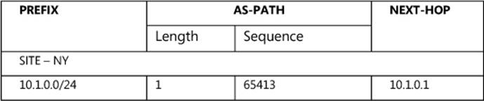
Based on this information, BGP running in the Woodgrove Bank compartment tries to perform a recursive route lookup for 10.1.0.1 and determines that 10.1.0.1 is reachable via the S2S VPN interface IfWe1 based on the route added on the interface. It deduces that 10.1.0.0/24 is reachable via the S2S VPN interface IfWe1 and adds this route on interface IfWe1. After this route has been added, packets in the Woodgrove Bank compartment with destination matching 10.1.0.0/24 are routed over interface IfWe1. Similar route updates from the BGP peer in SFO result in the route 10.2.0.0/24 being added on the S2S VPN interface IfWe2.
Since the NY and SFO sites of Woodgrove Bank are connected, it is possible to configure third-party BGP routers at the NY edge network to advertise routes learned from SFO to the Woodgrove Bank virtual network in Fabrikam. Similarly a third-party router at the SFO edge network can be configured to advertise routes learned from NY to the virtual network in Fabrikam.
Next examine how BGP running in the Woodgrove Bank compartment handles these routes and makes it easy when compared to the static route configuration discussed earlier. BGP in the Woodgrove Bank compartment receives the following relevant information in update messages from its peers in NY and SFO:
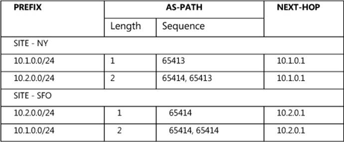
For routes 10.1.0.0/24 and 10.2.0.0/24, two routes are advertised, one with AS path length 2 and another with AS path length 1. BGP prefers routes with shortest AS path length and therefore routes packets to 10.1.0.0/24 via ASN 65413 (NY site) and to 10.2.0.0/24 via ASN 65414 (SFO site). If the S2S VPN tunnel between NY and Fabrikam goes down, BGP peering is also torn down (after a configured time-out) and all the routes learned from NY are discarded. BGP then re-computes the best path for 10.1.0.0/24 and 10.2.0.0/24. It finds that the best path for 10.2.0.0/24 has not changed and retains the route via SFO. It finds that the old path to 10.1.0.0/24 via NY no longer exists and determines the new best path to 10.1.0.0/24 is via SFO, so it adds the route 10.1.0.0/24 on the S2S VPN interface IfWe2 so that packets are routed to NY via SFO. Note that re-routing is taken care of by BGP without any manual intervention and all this happens in a matter of seconds.
The above explanation describes the routing details of tenant Woodgrove Bank on a multi-tenant service provider’s edge gateway. As explained previously, Windows Server 2012 R2 can be deployed for routing of traffic of multiple tenants with overlapping IP addresses. In the example, the Fabrikam edge gateway is configured with two tenants (Contoso and Woodgrove Bank) that have an overlapping IP address space. Both of these tenants can enable BGP routing with overlapping ASNs and prefixes. Isolation of routing information is maintained by storing routes using Windows Route Table Manager v2 (RTMv2) (see http://msdn.microsoft.com/en-us/library/windows/desktop/aa373798(v=vs.85).aspx). This enables the configuration of multiple virtual BGP routers, one per routing domain. To enable and configure BGP routing for the other tenant, Contoso, the cmdlets are the same but the value of the RoutingDomain parameter changes to “Contoso” with the BgpIdentifier as the IPv4 address of IfCi1. The values for other parameters can be substituted similarly.
Multi-tenant Network Address Translation
Multi-tenant Network Address Translation (NAT) in Windows Server 2012 R2 can enable cloud service provider Fabrikam to enable VMs that have overlapping IP addresses on virtual networks for Woodgrove Bank and Contoso, Ltd hosted in Fabrikam to access services on the Internet.
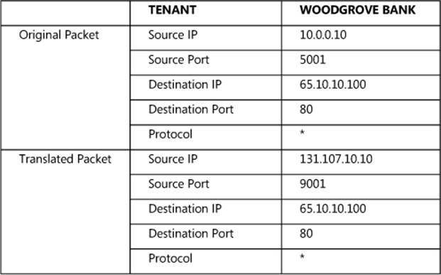
Woodgrove Bank has a VM with IP address 10.0.0.10 in its virtual network hosted in Fabrikam. An application in this VM that binds to source port 5001 needs to access port 80 of an Internet server 65.10.10.100. Since IP address 10.0.0.10 is not routable on the Internet, when the packet exits the Fabrikam network, the IP address of the packet is translated to the public IP address 131.107.10.10. The NAT mapping table on the NAT gateway is shown here:
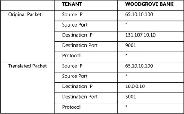
When the return packet comes from 65.10.10.100 to the Fabrikam network, the following NAT mapping table is used:
For a regular single-tenant NAT, just translating the destination IP address and port would be good enough. With multi-tenancy, however, since there are multiple tenants with the same destination IP address 10.0.1.1, the NAT should also map the IP or port to the appropriate tenant. This is achieved by maintaining the mapping of the VSID with the tuple.
Figure 2-12 shows VMs with IP addresses 10.0.0.10 for the two tenants Woodgrove Bank and Contoso trying to access a web page hosted on a web server with IP address 65.10.10.10. When the packets are routed to the multi-tenant gateway, they end up in their respective compartments. Since 65.10.10.10 is reachable only via the Internet, there will not be any matching route in the Woodgrove Bank or Contoso compartment. If multi-tenant NAT is enabled and there is no matching route for the destination in the tenant compartment, the packets are translated by NAT with the configured Internet address.
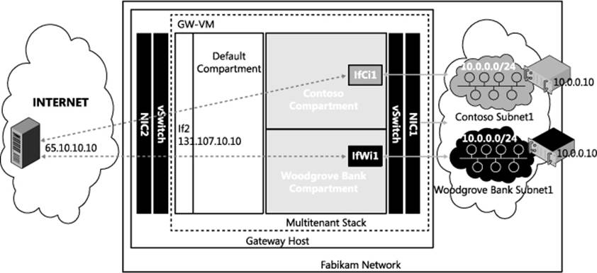
FIGURE 2-12 Multi-tenant NAT.
The following cmdlets show how to enable multi-tenant NAT:
New-NetNat -Name Contoso -ExternalIPInterfaceAddressPrefix 131.107.10.12/32
-InternalRoutingDomainId "{12345678-1000-2000-3000-123456780001}"
New-NetNat -Name Woodgrove -ExternalIPInterfaceAddressPrefix 131.107.10.13/32
-InternalRoutingDomainId "{12345678-1000-2000-3000-123456780002}"
Add-NetNatExternalAddress -NatName MT-NAT-Contoso -IPAddress 131.107.10.12
-PortStart 443 -PortEnd 443
Add-NetNatStaticMapping -NatName MT-NAT-Contoso -Protocol "TCP"
-ExternalIPAddress 131.107.10.12 -ExternalPort 443 -InternalIPAddress 10.0.0.100
-Internal Port 443