CCNA Wireless 200-355 Official Cert Guide (2016)
Chapter 12. Understanding Roaming
This chapter covers the following topics:
![]() Roaming Overview—This section reviews the fundamentals of wireless client mobility between autonomous access points and between APs that are joined to a common controller.
Roaming Overview—This section reviews the fundamentals of wireless client mobility between autonomous access points and between APs that are joined to a common controller.
![]() Roaming Between Centralized Controllers—This section covers wireless client mobility between APs that are bound to different centralized controllers. It also explains how client mobility can be scaled as a network grows.
Roaming Between Centralized Controllers—This section covers wireless client mobility between APs that are bound to different centralized controllers. It also explains how client mobility can be scaled as a network grows.
![]() Roaming Between Converged Controllers—This section explains wireless client mobility when APs are bound to different converged controllers in the access layer. Cisco also calls this New Mobility.
Roaming Between Converged Controllers—This section explains wireless client mobility when APs are bound to different converged controllers in the access layer. Cisco also calls this New Mobility.
This chapter covers the following exam topics:
![]() 5.4—Describe roaming
5.4—Describe roaming
![]() 5.4a—Layer 2 and Layer 3
5.4a—Layer 2 and Layer 3
![]() 5.4b—Intracontroller and intercontroller
5.4b—Intracontroller and intercontroller
![]() 5.4c—Centralized mobility
5.4c—Centralized mobility
![]() 5.4d—Converged mobility
5.4d—Converged mobility
Wireless client devices are inherently mobile, so you should expect them to move around. This chapter discusses client mobility from the AP and controller perspectives. You should have a good understanding of client roaming so that you can design and configure your wireless network properly as it grows over time.
“Do I Know This Already?” Quiz
The “Do I Know This Already?” quiz allows you to assess whether you should read this entire chapter thoroughly or jump to the “Exam Preparation Tasks” section. If you are in doubt about your answers to these questions or your own assessment of your knowledge of the topics, read the entire chapter. Table 12-1 lists the major headings in this chapter and their corresponding “Do I Know This Already?” quiz questions. You can find the answers in Appendix A, “Answers to the ‘Do I Know This Already?’ Quizzes.”
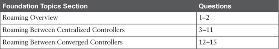
Table 12-1 “Do I Know This Already?” Section-to-Question Mapping
Caution
The goal of self-assessment is to gauge your mastery of the topics in this chapter. If you do not know the answer to a question or are only partially sure of the answer, you should mark that question as wrong for purposes of the self-assessment. Giving yourself credit for an answer you correctly guess skews your self-assessment results and might provide you with a false sense of security.
1. When a client moves its association from one autonomous AP to another, it is actually leaving and joining which one of the following?
a. SSID
b. BSS
c. ESS
d. DS
2. Which one of the following makes the decision for a device to roam from one AP to another?
a. The client device
b. The original AP
c. The candidate AP
d. The wireless LAN controller
3. Ten lightweight APs are joined to a wireless LAN controller. If a client roams from one of the APs to another, which one of the following correctly describes the roam?
a. Autonomous roaming
b. Intercontroller roaming
c. Intracontroller roaming
d. Indirect roaming
4. Which one of the following provides the most efficient means for roaming, as measured by the time to complete the roam?
a. Layer 2 intercontroller roaming
b. Layer 3 intercontroller roaming
c. Intracontroller roaming
d. All of these answers because each takes an equal amount of time
5. Which one of the following is used to cache authentication key information to make roaming more efficient?
a. PGP
b. CCNA
c. CCKM
d. EoIP
6. The term Layer 3 roaming refers to which one of the following types of client roam in a Cisco unified wireless network?
a. Autonomous AP roaming
b. Intracontroller roaming
c. Intercontroller roaming
d. RRM roaming
7. In a Layer 2 roam, what mechanism is used to tunnel client data between the two controllers?
a. GRE tunnel
b. EoIP tunnel
c. CAPWAP tunnel
d. None of these answers
8. When a client roams from one controller to another, it must obtain a new IP address from a DHCP server. True or false?
a. True
b. False
9. A client roams from controller A to controller B. If it undergoes a Layer 3 roam, which one of the following best describes the role of controller A?
a. Foreign controller
b. Host controller
c. Master controller
d. Anchor controller
10. A network consists of four controllers: A, B, C, and D. Mobility group 1 consists of controllers A and B, while mobility group 2 consists of controllers C and D. Which one of the following answers describes what will happen when a client tries to roam between controllers B and C?
a. Roaming is seamless and efficient.
b. Roaming is not possible.
c. Roaming is possible, but CCKM and key caching will not work.
d. Only Layer 3 roaming is possible.
11. Which one of the following controller functions terminates CAPWAP tunnels from lightweight APs?
a. MO
b. MA
c. MC
d. MD
12. Before mobility can be successfully implemented in a Cisco converged wireless network, a controller designated as a Mobility Anchor must be linked with which one of the following?
a. MC
b. MD
c. MA
d. MO
13. Which one of the following roles is used to anchor a wireless client and its IP address to a wired network and IP subnet?
a. PoP
b. PoA
c. PoE
d. PoC
e. PoD
14. In a Cisco converged wireless network, multiple controllers can be grouped together into which one of the following entities to make localized roaming more efficient?
a. High availability group
b. Mobility Domain
c. Mobility Subdomain
d. Mobility Peer Group
e. Switch Peer Group
15. Each converged controller that is in the access layer must function as which one of the following roles?
a. MO
b. MA
c. MC
d. ME
Foundation Topics
When a wireless client moves about, the expectations are simple—good, seamless coverage wherever the client goes. Clients know how to roam between access points (APs), but they are ignorant about the wireless network infrastructure. Even in a large network, roaming should be easy, quick, and not disrupt the client’s service.
Cisco wireless networks offer several roaming strategies. From your perspective as a wireless engineer, roaming configuration is straightforward. The inner workings can be complex, depending on the size of the wireless network as measured by the number of APs and controllers. As you work through the sections in this chapter, you will review roaming fundamentals, then learn more about how the Cisco wireless controllers handle client roaming and how to configure your controllers to support it properly.
Roaming Overview
To understand how wireless roaming works, you should start simple. The following two sections discuss roaming between access points when no controller is present and when only one controller is present. More complex scenarios are covered later in the chapter.
Roaming Between Autonomous APs
In Chapter 6, “Understanding 802.11 Frame Types,” you learned that a wireless client can move from one basic service set (BSS) to another by roaming between APs. A client continuously evaluates the quality of its wireless connection. If the signal quality degrades, the client begins looking for an AP with a better signal. The process is usually quick and simple; active scanning reveals candidate APs, and then the client selects one and tries to reassociate with it.
Figure 12-1 shows a simple scenario with two APs and one client. The client begins with an association to AP-1. Because the APs are running in autonomous mode, each one maintains a table of its associated clients. AP-1 has one client; AP-2 has none.
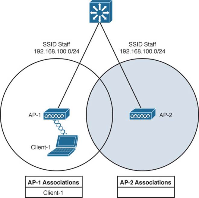
Figure 12-1 Before Roaming Between Autonomous APs
Suppose that the client then begins to move into AP-2’s cell. Somewhere near the cell boundary, the client decides that the signal from AP-1 has degraded and it should look elsewhere for a stronger signal. The client decides to roam and reassociate with AP-2. Figure 12-2 shows the new scenario after the roam occurs. Notice that both APs have updated their list of associated clients to reflect Client-1’s move from AP-1 to AP-2. If AP-1 still has any leftover wireless frames destined for the client after the roam, it forwards them to AP-2 over the wired infrastructure—simply because that is where the client’s MAC address now resides.
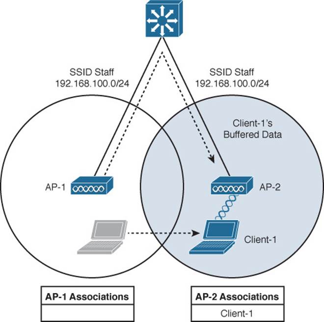
Figure 12-2 After Roaming Between Autonomous APs
Naturally, roaming is not limited to only two APs; instead, it occurs between two APs at any given time. To cover a large area, you will probably install many APs in a pattern such that their cells overlap. Figure 12-3 shows a typical pattern. When a wireless client begins to move, it might move along an arbitrary path. Each time the client decides that the signal from one AP has degraded enough, it attempts to roam to a new, better signal from a different AP and cell. The exact location of each roam depends on the client’s roaming algorithm. To illustrate typical roaming activity, each roam in Figure 12-3 is marked with a dark ring.
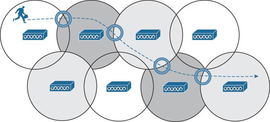
Figure 12-3 Successive Roams of a Mobile Client
Intracontroller Roaming
In a Cisco wireless network, lightweight APs are bound to a wireless LAN controller through CAPWAP tunnels. The roaming process is similar to that of autonomous APs; clients must still reassociate to new APs as they move about. The only real difference is that the controller handles the roaming process because of the split-MAC architecture.
Figure 12-4 shows a two-AP scenario where both APs connect to a single controller. Client-1 is associated to AP-1, which has a Control and Provisioning of Wireless Access Points (CAPWAP) tunnel to controller WLC-1. The controller maintains a client database that contains detailed information about how to reach and support each client. For simplicity, Figure 12-4 shows the database as a list of the controller’s APs, associated clients, and the wireless LAN (WLAN) being used. The actual database also contains client MAC and IP addresses, quality of service (QoS) parameters, and other information.
![]()
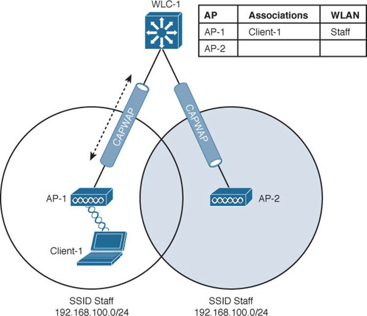
Figure 12-4 Cisco Wireless Network Before an Intracontroller Roam
When Client-1 starts moving, it eventually roams to AP-2, as shown in Figure 12-5. Not much has changed except that the controller has updated the client association from AP-1 to AP-2. Because both APs are bound to the same controller, the roam occurs entirely within the controller. This is known as intracontroller roaming.
![]()
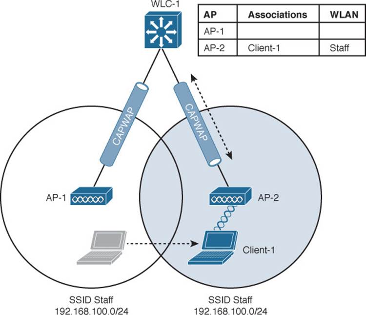
Figure 12-5 Cisco Wireless Network After an Intracontroller Roam
If both APs involved in a client roam are bound to the same controller, the roaming process is simple and efficient. The controller has to update its client association table so that it knows which CAPWAP tunnel to use to reach the client. Thanks to the simplicity, an intracontroller roam takes less than 10 ms to complete—the amount of processing time needed for the controller to switch the client entry from AP-1 to AP-2. From the client’s perspective, an intracontroller roam is no different than any other roam. The client has no knowledge that the two APs are communicating with a controller over CAPWAP tunnels; it simply decides to roam between two APs based on its own signal analysis.
Efficient roaming is especially important when time-critical applications are being used over the wireless network. For example, wireless phones need a consistent connection so that the audio stream is not garbled or interrupted. When a roam occurs, there could be a brief time when the client is not fully associated with either AP. So long as that time is held to a minimum, the end user probably will not even notice that the roam occurred.
Along with the client reassociation, a couple of other processes can occur:
![]() DHCP—The client may be programmed to renew the DHCP lease on its IP address or to request a new address.
DHCP—The client may be programmed to renew the DHCP lease on its IP address or to request a new address.
![]() Client authentication—The controller might be configured to use an 802.1x method to authenticate each client on a WLAN.
Client authentication—The controller might be configured to use an 802.1x method to authenticate each client on a WLAN.
To achieve efficient roaming, both of these processes should be streamlined as much as possible. For instance, if a client roams and tries to renew its IP address, it is essentially cut off from the network until the Dynamic Host Configuration Protocol (DHCP) server responds.
The client authentication process presents the biggest challenge because the dialog between a controller and a RADIUS server, in addition to the cryptographic keys that need to be generated and exchanged between the client and an AP or controller, can take a considerable amount of time to accomplish. Cisco controllers offer three techniques to minimize the time and effort spent on key exchanges during roams:
![]() Cisco Centralized Key Management (CCKM)—One controller maintains a database of clients and keys on behalf of its APs and provides them to other controllers and their APs as needed during client roams. CCKM requires Cisco Compatible Extensions (CCX) support from clients.
Cisco Centralized Key Management (CCKM)—One controller maintains a database of clients and keys on behalf of its APs and provides them to other controllers and their APs as needed during client roams. CCKM requires Cisco Compatible Extensions (CCX) support from clients.
![]() Key caching—Each client maintains a list of keys used with prior AP associations and presents them as it roams. The destination AP must be present in this list, which is limited to eight AP-key entries.
Key caching—Each client maintains a list of keys used with prior AP associations and presents them as it roams. The destination AP must be present in this list, which is limited to eight AP-key entries.
![]() 802.11r—An 802.11 amendment that addresses fast roaming or fast BSS transition; a client can cache a portion of the authentication server’s key and present that to future APs as it roams. The client can also maintain its QoS parameters as it roams.
802.11r—An 802.11 amendment that addresses fast roaming or fast BSS transition; a client can cache a portion of the authentication server’s key and present that to future APs as it roams. The client can also maintain its QoS parameters as it roams.
Each of the fast-roaming strategies requires help on the part of the wireless client. That means the client must have a supplicant or driver software that is compatible with fast roaming and can cache the necessary pieces of the authentication credentials.
Roaming Between Centralized Controllers
As a wireless network grows, one controller might not suffice. When two or more controllers support the APs in an enterprise, the APs can be distributed across them. As always, when clients become mobile, they roam from one AP to another—except they could also be roaming from one controller to another, depending on how neighboring APs are assigned to the controllers. As a network grows, AP roaming can scale too by organizing controllers into mobility groups. The following sections cover intercontroller roaming, mobility groups, and the mechanisms used to coordinate roaming.
Layer 2 Roaming
When a client roams from one AP to another and those APs lie on two different controllers, the client makes an intercontroller roam. Figure 12-6 shows a simple scenario prior to a roam. Controller WLC-1 has one association in its database—that of Client-1 on AP-1. Figure 12-7 shows the result of the client roaming to AP-2.
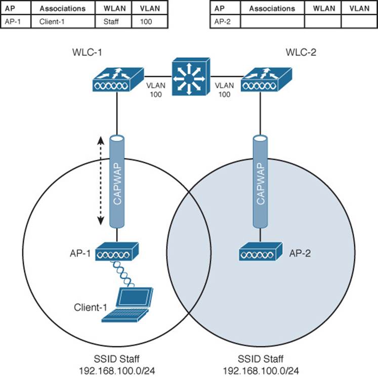
Figure 12-6 Before an Intercontroller Roam
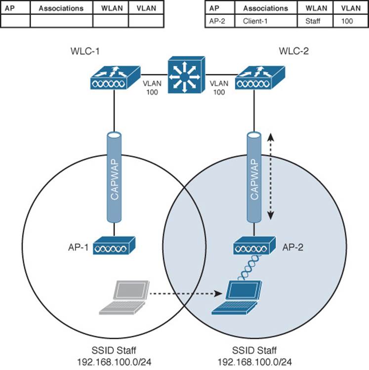
Figure 12-7 After an Intercontroller Roam
The roam itself is fairly straightforward. When the client decides to roam and reassociate itself with AP-2, it actually moves from one controller to another and the two controllers must coordinate the move. One subtle detail involves the client’s IP address. Before the roam, Client-1 is associated with AP-1 and takes an IP address from the VLAN and subnet that are configured on the WLAN supplied by controller WLC-1. In Figure 12-6, WLAN Staff is bound to VLAN 100, so the client uses an address from the 192.168.100.0/24 subnet.
When the client roams to a different AP, it can try to continue using its existing IP address or work with a DHCP server to either renew or request an address. Figure 12-7 shows the client roaming to AP-2, where WLAN Staff is also bound to the same VLAN 100 and 192.168.100.0/24 subnet. Because the client has roamed between APs but stayed on the same VLAN and subnet, it has made a Layer 2 intercontroller roam. Layer 2 roams (commonly called local-to-local roams) are nice for two reasons: The client can keep its same IP address, and the roam is fast (usually less than 20 ms).
Layer 3 Roaming
What if a wireless network grows even more, such that the WLAN interfaces on each controller are assigned to different VLANs and subnets? Breaking a very large WLAN up into individual subnets seems like a good idea from a scalability viewpoint. However, when a wireless client roams from one controller to another, it could easily end up on a different subnet than it started with.
Clients will not usually be able to detect that they have changed subnets. They will be aware of the AP roam but little else. Only clients that aggressively contact a DHCP server after each and every roam will continue to work properly. But to make roaming seamless and efficient, time-consuming processes such as DHCP should be avoided.
No worries—the Cisco wireless network has a clever trick up its sleeve. When a client initiates an intercontroller roam, the two controllers involved can compare the VLAN numbers that are assigned to their respective WLAN interfaces. If the VLAN IDs are the same, nothing special needs to happen; the client undergoes a Layer 2 intercontroller roam and can continue to use its original IP address on the new controller. If the two VLAN IDs differ, the controllers arrange a Layer 3 roam (also known as a local-to-foreign roam) that will allow the client to keep using its IP address.
Figure 12-8 illustrates a simple wireless network containing two APs and two controllers. Notice that the two APs offer different IP subnets in their BSSs: 192.168.100.0/24 and 192.168.200.0/24. The client is associated with AP-1 and is using IP address 192.168.100.199. On the surface, it looks like the client will roam into subnet 192.168.200.0/24 if it wanders into AP-2’s cell, and will lose connectivity if it tries to keep using its same IP address.
![]()
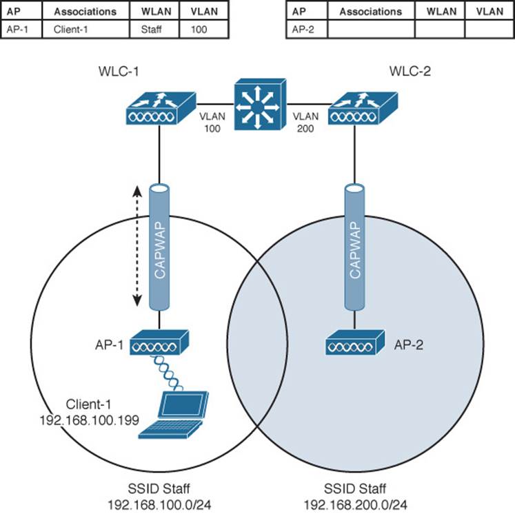
Figure 12-8 Before a Layer 3 Intercontroller Roam
A Layer 3 intercontroller roam consists of an extra tunnel that is built between the client’s original controller and the controller it has roamed to. The tunnel carries data to and from the client as if it is still associated with the original controller and IP subnet. Figure 12-9 shows the results of a Layer 3 roam. The original controller (WLC-1) is called the anchor controller, and the controller with the roamed client is called the foreign controller. Think of the client being anchored to the original controller no matter where it roams later. When the client roams away from its anchor, it moves into foreign territory.
![]()
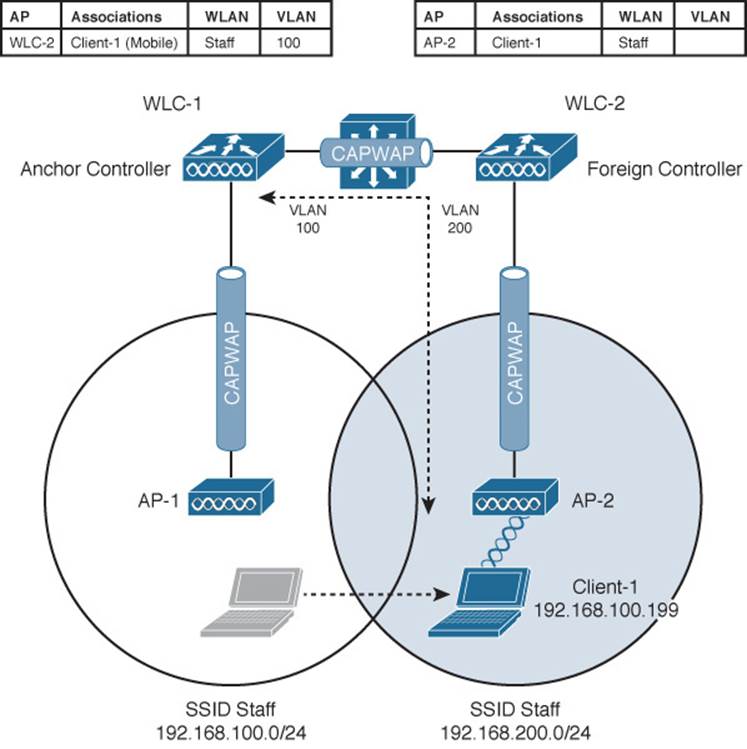
Figure 12-9 After a Layer 3 Intercontroller Roam
You can see clients that have undergone a Layer 3 roam by selecting Monitor > Clients from the controller graphical user interface (GUI). The client from Figures 12-8 and 12-9 is shown in the WLC-1 client list displayed in Figure 12-10. Notice that the client’s protocol is shown as 802.11(Mobile); other clients would be listed as 802.11 only.
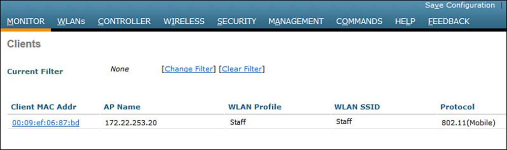
Figure 12-10 Displaying Clients with a Layer 3 Intercontroller Roam
You can click the client’s MAC address to see more details about its state. In Figure 12-11, you can see that the controller has mobility role Anchor and that the Layer 3 mobility peer is 172.22.253.20, or WLC-2.
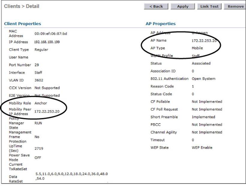
Figure 12-11 Displaying Client Details on the Anchor Controller
Due to the Layer 3 roam, the client should have an active association with both the anchor and foreign controllers. On the foreign controller, you can view the client details from a different perspective. In Figure 12-12, the client is shown associated with a foreign controller with IP address 172.22.253.9, or WLC-1. On the foreign controller, the client is associated to an actual AP (AP-2) with a normal AP type.
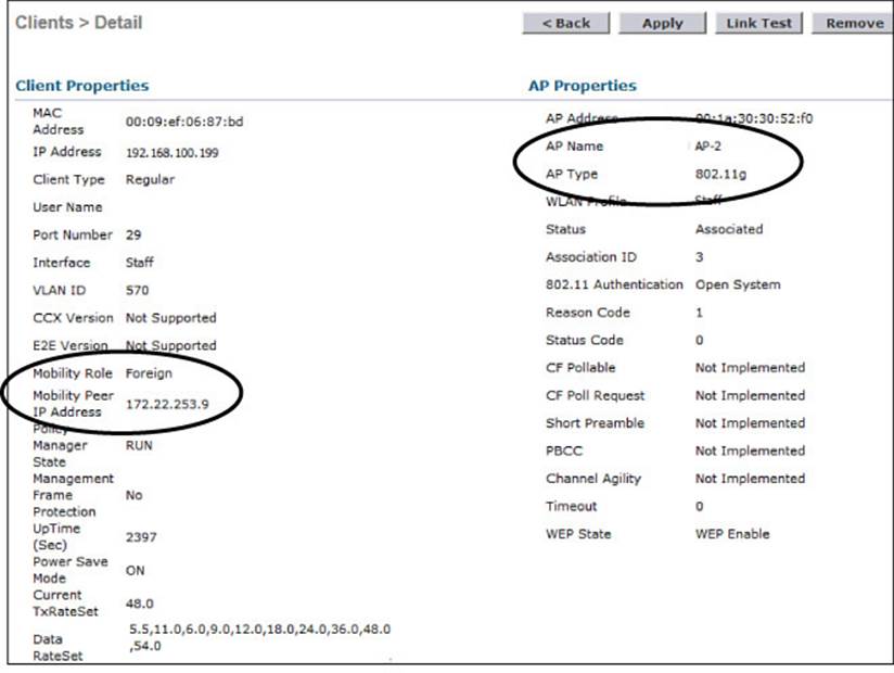
Figure 12-12 Displaying Client Details on the Foreign Controller
Recall that Cisco controllers use CAPWAP tunnels to connect with lightweight APs. CAPWAP tunnels are also built between controllers for Layer 3 roaming. The tunnel tethers the client to its original anchor controller (and original IP subnet), regardless of its location or how many controllers it roams through.
Anchor and foreign controllers are normally determined automatically. When a client first associates with an AP and controller, that controller becomes its anchor controller. When the client roams to a different controller, that controller can take on the foreign role. Sometimes you might not want a client’s first controller to be its anchor. For example, guest users should not be allowed to associate with just any controller in your network. Instead, you might want guests to be forced onto a specific controller that is situated behind a firewall or contained in a protected environment. You can configure one controller to be a static anchor for a WLAN so that other controllers will direct clients toward it through Layer 3 roaming tunnels. Static anchor controllers are covered in more detail in Chapter 16, “Implementing a Wireless Guest Network.”
Scaling Mobility with Mobility Groups
Cisco controllers can be organized into mobility groups to facilitate intercontroller roaming. Mobility groups become important as a wireless network scales and there are more centralized controllers cooperating to provide coverage over a large area.
If two centralized controllers are configured to belong to the same mobility group, clients can roam quickly between them. Layer 2 and Layer 3 roaming are both supported, along with CCKM, key caching, and 802.11r credential caching. If two controllers are assigned to different mobility groups, clients can still roam between them, but the roam is not very efficient. Credentials are not cached and shared, so clients must go through a full authentication during the roam.
Mobility groups have an implied hierarchy as shown in Figure 12-13. Each controller maintains a mobility list that contains its own MAC address and the MAC addresses of other controllers. Each controller in the list is also assigned a mobility group name. In effect, the mobility list gives a controller its view of the outside world; it knows of and trusts only the other controllers configured in the list. If two controllers are not listed in each other’s mobility list, they are unknown to each other and clients will not be able to roam between them. Clients will have to associate and authenticate from scratch.
![]()
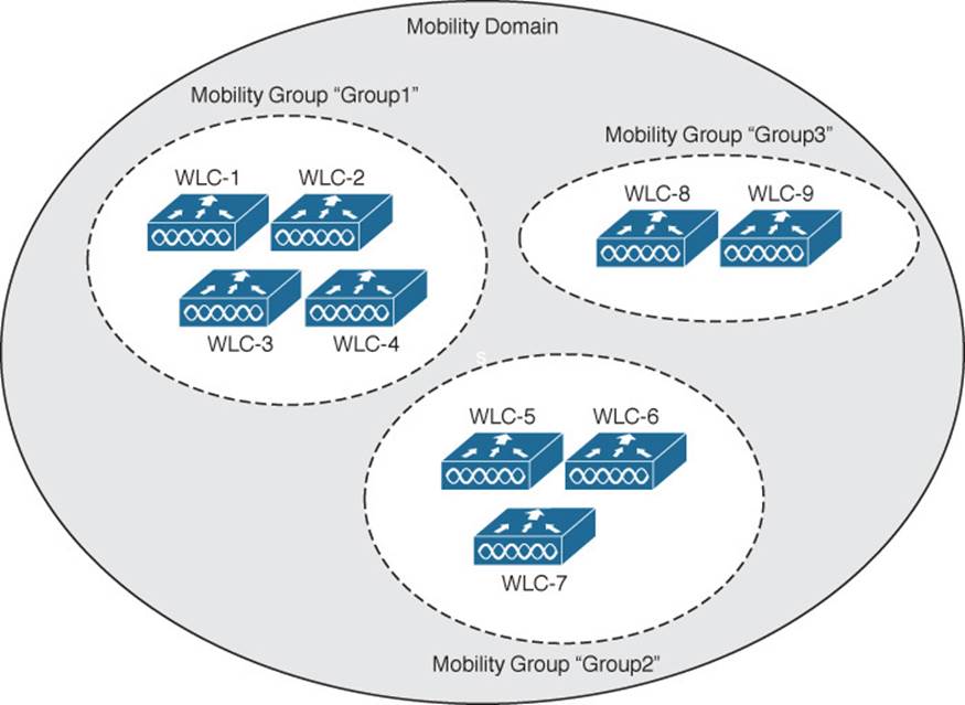
Figure 12-13 Mobility Group Hierarchy
You can think of this list as a Mobility Domain. In a centralized controller environment, the list can contain up to 72 controllers, with up to 24 controllers in each mobility group.
To configure a mobility group, use the following steps:
Step 1. Visit each member controller and enter a mobility group name under Controller > General > Default Mobility Domain Name.
Step 2. Select Controller > Mobility Management > Mobility Groups. Click the New button to add one controller MAC address at a time to the group. Otherwise, you can select the EditAll button to populate the controller’s mobility list with the MAC and IP addresses of other controllers and their mobility group names. The local controller should be the first entry in the list. Click the Apply button to make the list entries active.
Step 3. Once you have entered each of the controllers in the mobility group list on each controller, verify that the controllers have joined the group and can communicate with each other. Look on the Controller > Mobility Management > Mobility Groups page and make sure each controller is listed with “up” in the Status column.
Roaming Coordination with Centralized Controllers
As a mobile client roams between APs, controllers must keep track of its movements, updating tables and building CAPWAP tunnels between controllers if necessary. All of this activity must be coordinated among the controllers that are configured to be part of a mobility group. To do this, controllers have some distinct roles and functions that play important parts in the roaming process.
A Mobility Agent (MA) is a controller function that handles mobility tasks facing the clients. For example, an MA terminates the CAPWAP tunnels that connect the controller to the APs that have joined it. An MA also maintains a database of all client associations. Because the MA function faces the clients, it is in a convenient location to handle any security, QoS, and other policies that affect client activity.
In contrast, a Mobility Controller (MC) is a function further upstream that manages roaming for one or more Mobility Agents. It also performs higher-level tasks, such as Cisco Radio Resource Management (RRM) and wireless intrusion protection system (wIPS), and manages guest wireless access.
Figure 12-14 shows the MA and MC functions in the context of a centralized wireless network. Notice that both functions are located in the controller. The MC is located there because every centralized controller must operate as an MC. The MA is also there because the client AP CAPWAP tunnels terminate there.
![]()
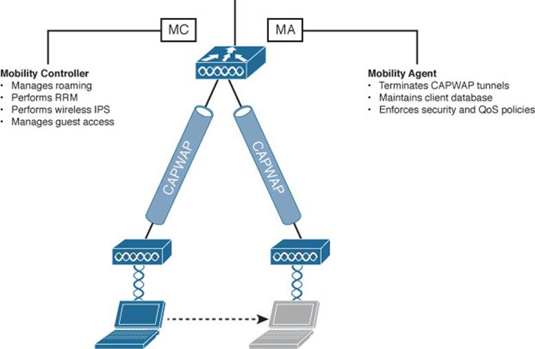
Figure 12-14 MC and MA Locations in a Centralized Wireless Network
The MC and MA perform their functions from a controller’s perspective. There are also two roaming coordination roles that exist from the client’s perspective:
![]() Point of Presence (PoP)—The WLC that anchors a client’s IP address, where the client meets the wired network. This is the point where the wireless client’s MAC address is seen from the perspective of the wired network. The PoP is also the point at which security policies that affect the client are applied.
Point of Presence (PoP)—The WLC that anchors a client’s IP address, where the client meets the wired network. This is the point where the wireless client’s MAC address is seen from the perspective of the wired network. The PoP is also the point at which security policies that affect the client are applied.
![]() Point of Attachment (PoA)—The WLC that terminates the CAPWAP tunnel to the AP where a client is currently located. The PoA is also the point at which QoS and roaming policies can be applied, closest to the client.
Point of Attachment (PoA)—The WLC that terminates the CAPWAP tunnel to the AP where a client is currently located. The PoA is also the point at which QoS and roaming policies can be applied, closest to the client.
Figure 12-15 shows where the PoP and PoA roles are located in a centralized wireless network with a single controller. Regardless of which AP the client is associated with, both PoP and PoA roles are located at the controller.
![]()
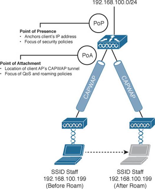
Figure 12-15 PoP and PoA Locations in a Centralized Wireless Network
So far, the MC, MA, PoP, and PoA have all been shown to exist on the same controller. What is the point of having all of these distinct functions if they all sit in the same place? The four functions have a somewhat limited use in a centralized wireless network because every controller must act as an MC and an MA. As you will see in the next section, the MC and MA become more distributed in a converged wireless network.
The PoP and PoA are actually dynamic roles that can move around as a client becomes mobile. This becomes more evident with multiple controllers, as shown in Figure 12-16. Each client has its own PoP and PoA; the PoP always stays with the initial controller that a client joins. You might have realized that the PoP sounds oddly similar to an anchor controller. As a client roams to other APs (and controllers), the PoA follows it.
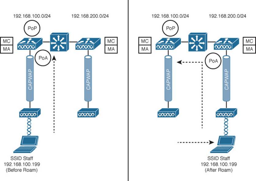
Figure 12-16 Roaming Functions Before (left) and After (right) a Roam
Roaming Between Converged Controllers
Now that you are more familiar with the MC and MA functions, you will see how roaming is coordinated in a converged wireless network. Recall from Chapter 8, “Understanding Cisco Wireless Architectures,” that a converged network is built by pushing the WLC down into the access layer switches in the form of a Wireless Controller Module (WCM). As a result, the number of APs per WCM is greatly reduced while the number of WCMs may greatly increase. To handle this shift, the converged controllers must be organized into a more scalable hierarchy.
Figure 12-17 illustrates the complete mobility hierarchy, with examples of several common types of controller groupings. There are several distinct layers or group types, which are described in Table 12-2. To get your bearings, first focus on the grouping at the left side of the figure. Notice that there are three controllers labeled “MA.” Each of these is a converged controller (WCM) with CAPWAP tunnels connecting to lightweight APs. The MA controllers are all logically connected to an MC, and the MA and MC roles are contained in a single mobility group. That should look familiar from the traditional or centralized roaming structure.
![]()
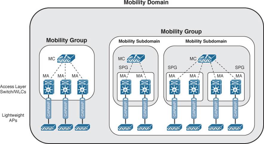
Figure 12-17 Mobility Hierarchy in a Converged Wireless Network
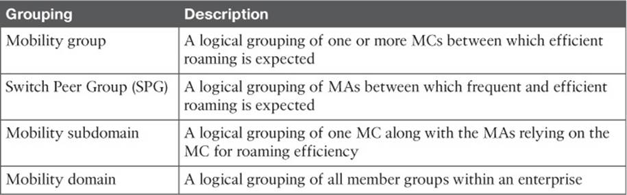
Table 12-2 Converged Controller Roaming Hierarchy
Tip
Although the MC and MA functions are shown as separate WCMs in Figure 12-17, a WCM can act as both an MA and an MC.
The key to the converged roaming hierarchy is that each WCM functions as an MA and must be joined to an MC. Sometimes the MC function is performed by a separate controller higher up in the network topology. In that case, the MC must be a traditional centralized controller that is configured for converged or “new” mobility. More commonly, the MC is a function that is enabled on one of the MAs. Each set of MAs and their MC form a mobility group.
Converged controllers (WCMs) can be configured as a logical Switch Peer Group (SPG), simplifying roaming between the WCMs. The MA members of the SPG must be joined to an MC somewhere in the network. Once the MAs join their MC, they form a full mesh of CAPWAP tunnels between themselves. Usually the WCMs in an SPG are all located within the same distribution block of the switched LAN. This tends to keep all roaming activity that occurs across neighboring APs within the same portion of the network so that the CAPWAP tunnels do not have to cross the network core layer.
SPGs are usually built from WCMs that serve the same geographic area where wireless clients are expected to roam. For example, an SPG might contain WCMs that serve APs in the same building, APs on adjacent floors in a building, or APs in the same general area. One or more SPGs and their MC then form a Mobility Subdomain. Further, multiple subdomains can be grouped into a single mobility group. In a very large network, multiple mobility groups or subdomains can be grouped into a single mobility domain.
Even though there can be an extensive hierarchy involved in a converged wireless network, roaming still occurs according to the same basic rules:
![]() The client’s PoP and PoA both begin at the initial WCM that is used. The PoP anchors the client’s IP address there.
The client’s PoP and PoA both begin at the initial WCM that is used. The PoP anchors the client’s IP address there.
![]() When a client roams, the PoA moves to the WCM where the client is now associated.
When a client roams, the PoA moves to the WCM where the client is now associated.
The most efficient roam is one that stays within the same WCM. A roam between WCMs in the same SPG is also efficient because the MAs automatically form a full mesh of CAPWAP tunnels to carry roaming traffic.
Roaming between WCMs that are members of different SPGs is not quite as efficient because client traffic must be tunneled through the MC that joins the two SPGs. It is also possible for a client to roam between two mobility subdomains or between two mobility groups. In those cases, the roaming gets less and less efficient, requiring intervention from MCs further and further up the hierarchy.
Exam Preparation Tasks
As mentioned in the section, “How to Use This Book,” in the Introduction, you have a couple of choices for exam preparation: the exercises here, Chapter 21, “Final Review,” and the exam simulation questions on the DVD.
Review All Key Topics
Review the most important topics in this chapter, noted with the Key Topic icon in the outer margin of the page. Table 12-3 lists a reference of these key topics and the page numbers on which each is found.
![]()
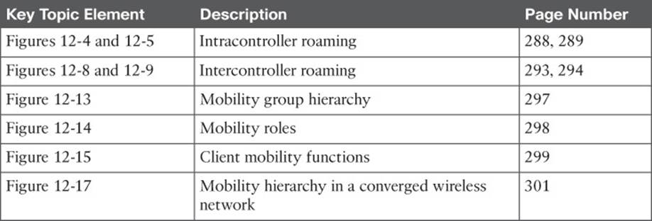
Table 12-3 Key Topics for Chapter 12
Define Key Terms
Define the following key terms from this chapter and check your answers in the glossary:
anchor controller
foreign controller
intercontroller roaming
intracontroller roaming
Layer 2 roam
Layer 3 roam
Mobility Agent (MA)
Mobility Controller (MC)
mobility domain
mobility group
mobility subdomain
Point of Attachment (PoA)
Point of Presence (PoP)
Switch Peer Group (SPG)
All materials on the site are licensed Creative Commons Attribution-Sharealike 3.0 Unported CC BY-SA 3.0 & GNU Free Documentation License (GFDL)
If you are the copyright holder of any material contained on our site and intend to remove it, please contact our site administrator for approval.
© 2016-2026 All site design rights belong to S.Y.A.