CCNA Wireless 200-355 Official Cert Guide (2016)
Chapter 4. Understanding Antennas
This chapter covers the following topics:
![]() Antenna Characteristics—This section describes the radiation pattern, gain, beamwidth, and polarization of an antenna.
Antenna Characteristics—This section describes the radiation pattern, gain, beamwidth, and polarization of an antenna.
![]() Antenna Types—This section covers the two basic types of antennas and their applications.
Antenna Types—This section covers the two basic types of antennas and their applications.
![]() Adding Antenna Accessories—This section explains several devices that can be added to an antenna to increase or reduce signal strength and to protect connected equipment from lightning damage.
Adding Antenna Accessories—This section explains several devices that can be added to an antenna to increase or reduce signal strength and to protect connected equipment from lightning damage.
This chapter covers the following exam topics:
![]() 1.4—Describe Wi-Fi antenna characteristics
1.4—Describe Wi-Fi antenna characteristics
![]() 1.4a—Ability to read a radiation pattern chart
1.4a—Ability to read a radiation pattern chart
![]() 1.4b—Antenna types and uses
1.4b—Antenna types and uses
![]() 1.4c—dBi, dBd, EIRP
1.4c—dBi, dBd, EIRP
Chapters 1 through 3 covered radio frequency (RF) signals, as used by 802.11 devices, and their propagation from the perspective of a transmitter and a receiver. By considering the link budget, or the net signal strength gain between a transmitter and receiver, you can make sure that a signal will arrive in good condition at its destination. The antenna gain is an important piece of the equation, but it does not completely describe an antenna’s construction or performance. This chapter explains some basic antenna theory, in addition to various types of antennas and their application.
“Do I Know This Already?” Quiz
The “Do I Know This Already?” quiz allows you to assess whether you should read this entire chapter thoroughly or jump to the “Exam Preparation Tasks” section. If you are in doubt about your answers to these questions or your own assessment of your knowledge of the topics, read the entire chapter. Table 4-1 lists the major headings in this chapter and their corresponding “Do I Know This Already?” quiz questions. You can find the answers in Appendix A, “Answers to the ‘Do I Know This Already?’ Quizzes.”
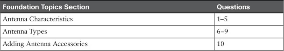
Table 4-1 “Do I Know This Already?” Section-to-Question Mapping
Caution
The goal of self-assessment is to gauge your mastery of the topics in this chapter. If you do not know the answer to a question or are only partially sure of the answer, you should mark that question as wrong for purposes of the self-assessment. Giving yourself credit for an answer you correctly guess skews your self-assessment results and might provide you with a false sense of security.
1. Which two of the following plots are used to show the radiation pattern of an antenna?
a. A plane
b. E plane
c. XY plane
d. H plane
e. YZ-plane
2. Which one of the following is another name for the H plane radiation pattern?
a. Horizon plane
b. Azimuth plane
c. Heat map
d. Lateral plane
3. Which one of the following answers correctly identifies the antenna parameter that is measured at 3 dB below the strongest point on a radiation pattern plot?
a. Half life
b. Decay point
c. Cut off point
d. Beamwidth
e. Sensitivity
4. The orientation of an electromagnetic wave is best described by which one of the following?
a. Phase
b. Amplitude
c. Modulation
d. Polarization
e. Azimuth
5. A Cisco dipole antenna is mounted so that it points straight upward and has a radiation pattern that extends in all directions horizontally. Which one of the following best describes the antenna’s likely polarization?
a. Horizontal polarization
b. Vertical polarization
c. Dual polarization
d. Elliptical polarization
6. Which one of the following antennas would probably have the greatest gain?
a. Patch
b. Dish
c. Yagi
d. Dipole
e. Integrated
7. An omnidirectional antenna usually has which of the following characteristics? (Choose two.)
a. Low gain
b. Small beamwidth
c. High gain
d. Zero gain
e. Large beamwidth
8. A standard indoor Cisco wireless access point is mounted on the ceiling and has antennas that are hidden inside the case. Which one of the following describes the antennas?
a. Patch antennas
b. Monopole antennas
c. Omnidirectional antennas
d. Isotropic antennas
9. A dipole antenna is connected to a transmitter. You would like to leverage the directional quality of the antenna. Based on the radiation pattern of the antenna, what would happen if you orient the antenna such that its cylindrical shape points directly at a distant receiver?
a. The receiver would pick up a stronger signal.
b. The receiver would pick up a weaker signal.
c. The antenna is omnidirectional, so the orientation would not matter.
d. This is pointless unless the receiver’s dipole is also aimed directly at the transmitter.
10. Which one of the following is not true about a lightning arrestor?
a. It is connected inline between a transmitter and an antenna.
b. It protects against large transient spikes of energy.
c. It protects against lightning strikes on an antenna.
d. It directs energy to the ground, rather than the transmitter equipment.
e. Every outdoor antenna needs one.
Foundation Topics
Antenna Characteristics
The world of wireless LANs would be rather simple if all antennas were created equal—too simple, in fact. To provide good wireless LAN coverage in a building, an outdoor area, or between two locations, you might be faced with a number of variables. For example, an office space might be arranged as a group of open cubicles or as a strip of closed offices down a long hallway. You might have to cover a large open lobby, a large open classroom, a section of a crowded sports arena, an oblong portion of a hospital roof where helicopters land, a large expanse of an outdoor park, city streets where public safety vehicles travel, and so on.
In other words, one type of antenna cannot fit every application. Instead, antennas come in many sizes and shapes, each with its own gain value and intended purpose. The following sections describe antenna characteristics in more detail.
Radiation Patterns
Recall from Chapter 1, “RF Signals and Modulation,” that antenna gain is normally a comparison of one antenna against an isotropic antenna, and is measured in dBi (decibel-isotropic). An isotropic antenna does not actually exist because it is ideal, perfect, and impossible to construct. It is also the simplest, most basic antenna possible, which makes it a good starting place for antenna theory.
An isotropic antenna is shaped like a tiny round point. When an alternating current is applied, an RF signal is produced and the electromagnetic waves are radiated equally in all directions. The energy produced by the antenna takes the form of an ever-expanding sphere. If you were to move all around an isotropic antenna at a fixed distance, you would find that the signal strength is the same.
To describe the antenna’s performance, you might draw a sphere with a diameter that is proportional to the signal strength, as shown in Figure 4-1. Most likely, you would draw the sphere on a logarithmic scale so that very large and very small numbers could be shown on the same linear plot. A plot that shows the relative signal strength around an antenna is known as the radiation pattern.
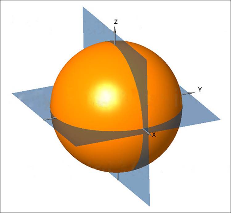
Figure 4-1 Plotting the Radiation Pattern of an Isotropic Antenna
It is rather difficult to show a three-dimensional plot or shape on a two-dimensional document—especially if the shape is complex or unusual. After all, most physical antennas are not ideal, so their radiation pattern is not a simple sphere. Instead, you could slice through the three-dimensional plot with two orthogonal planes and show the two outlines that are formed from the plot. In Figure 4-1, the sphere is cut by the XY plane, which lies flat along the horizon, and by the XZ plane, which lies vertically along the elevation of the sphere. Figure 4-2 shows the resulting cuts.
![]()
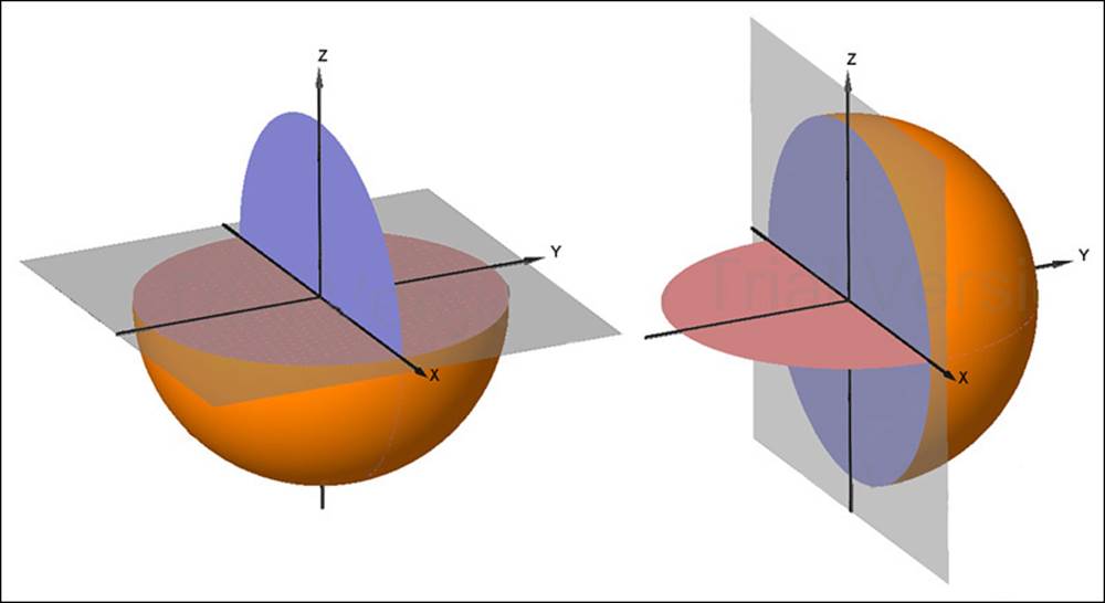
Figure 4-2 Cutting the Radiation Pattern with Two Planes
The plane at the left is known as the H plane or the horizontal (azimuth) plane, and usually shows a top-down view of the radiation pattern through the center of the antenna. The plane at the right is known as the E plane or elevation plane, and shows a side view of the same radiation pattern.
The outline of each plot can be recorded on a polar plot, as shown by the heavy dark lines in Figure 4-3. A polar plot contains concentric circles that represent relative changes in the signal strength as measured at a constant distance from the antenna. The outermost circle usually represents the strongest signal strength, and the inner circles represent weaker signal strength. Although the circles are labeled with numbers like 0, –5, –10, –15, and so on, they do not necessarily represent any absolute dB values. Instead, they are measurements that are relative to the maximum value at the outside circle. If the maximum is shown at the outer ring, everything else will be less than the maximum and will lie further inward.
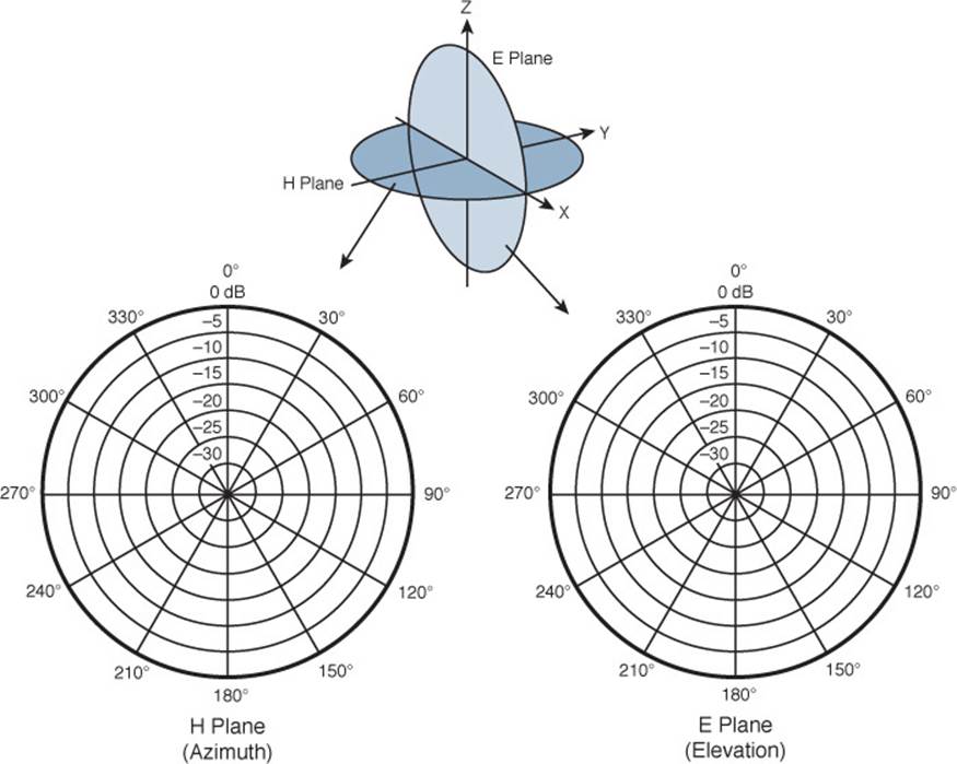
Figure 4-3 Recording an Isotropic Antenna Pattern on E and H Polar Plots
The circles are also divided into sectors so that a full sweep of 360 degrees can be plotted. This allows measurements to be taken at every angle around the antenna in the plane shown.
Are you confused? You aren’t alone. The E and H polar plots of the radiation pattern are presented here because most antenna manufacturers include them in their product literature. The antenna is always placed at the center of the polar plots, but you will not always be able to figure out how the antenna is oriented with respect to the E and H planes. Cisco usually includes a small picture of the antenna at the center of the plots as a handy reference.
As a wireless engineer, you will have to look at various antenna patterns and try to figure out whether the antenna is a good match for the environment you are trying to cover with an RF signal. You will need a good bit of imagination to merge the two plots into a 3D picture in your mind. As various antennas are described in this chapter, the plots, planes, and a 3D rendering are presented to help you get a feel for the thinking process.
Gain
Antennas are passive devices; they do not amplify a transmitter’s signal with any circuitry or external power. Instead, they amplify or add gain to the signal by shaping the RF energy as it is propagated into free space. In other words, the gain of an antenna is a measure of how effectively it can focus RF energy in a certain direction.
Because an isotropic antenna radiates RF energy in all directions equally, it cannot focus the energy in any certain direction. Recall from Chapter 1 that the gain of an antenna in dBi is measured relative to an isotropic antenna. When an isotropic antenna is compared with itself, the result is a gain of 10log10(1) or 0 dBi.
Think of a zero gain antenna producing a perfect sphere. If the sphere is made of rubber, you could press on it in various locations and change its shape. As the sphere is deformed, it expands in other directions. Figure 4-4 shows some simple examples, along with some example gain values. As you work through this chapter and examine antennas on your own, notice how the gain is lower for omnidirectional antennas, which are made to cover a widespread area, and higher for directional antennas, which are built to cover more focused areas.
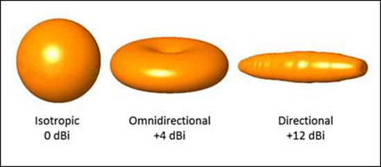
Figure 4-4 Radiation Patterns for the Three Basic Antenna Types
Tip
The gain itself is typically not indicated on either E or H plane radiation pattern plots. The only way to find an antenna’s gain is to look at the manufacturer’s specifications.
Beamwidth
The antenna gain can be an indicator of how focused an antenna’s pattern might be, but it is really more suited for link budget calculations. Instead, many manufacturers list the beamwidth of an antenna as a measure of the antenna’s focus. Beamwidth is normally listed in degrees for both the H and E planes.
The beamwidth is determined by finding the strongest point on the plot, which is usually somewhere on the outer circle. Next, the plot is followed in either direction until the value decreases by 3 dB, indicating the point where the signal is one-half the strongest power. A line is drawn from the center of the plot to intersect each 3-dB point, and then the angle between the two lines is measured. Figure 4-5 shows a simple example. The H plane has a beamwidth of 30 degrees, and the E plane has a beamwidth of 55 degrees.
![]()
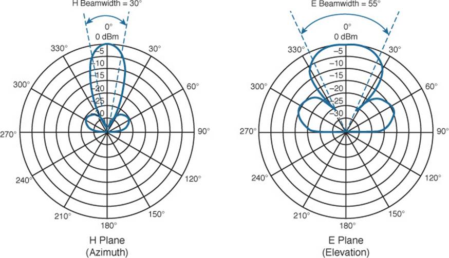
Figure 4-5 Example of Antenna Beamwidth Measurement
Polarization
When an alternating current is applied to an antenna, an electromagnetic wave is produced. From Chapter 1, you learned that the wave has two components: an electrical field wave and a magnetic field wave. The electrical portion of the wave will always leave the antenna in a certain orientation. For example, a simple dipole antenna that is mounted pointing vertically will produce a wave that oscillates up and down in a vertical direction as it travels through free space. This is true of most Cisco antennas when they are mounted according to Cisco recommendations. Other types of antennas might be designed to produce waves that oscillate back and forth horizontally. Still others might produce waves that actually twist in a three-dimensional spiral motion through space.
The electrical field wave’s orientation, with respect to the horizon, is called the antenna polarization. Antennas that produce vertical oscillation are vertically polarized; ones that produce horizontal oscillation are horizontally polarized. (Keep in mind that there is always a magnetic field wave too, which is oriented at 90 degrees from the electrical field wave.) By itself, the antenna polarization is not of critical importance. However, the antenna polarization at the transmitter must be matched to the polarization at the receiver. If the polarization is mismatched, the received signal can be severely degraded.
Figure 4-6 illustrates antenna polarization. The transmitter and receiver along the top both use vertical polarization, so the received signal is optimized. The pair along the bottom is mismatched, causing the signal to be poorly received.
![]()
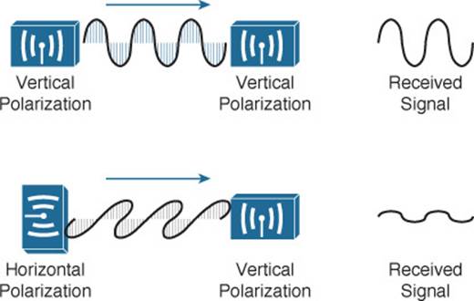
Figure 4-6 Matching the Antenna Polarization Between Transmitter and Receiver
Tip
Even though Cisco antennas are designed to use vertical polarization, someone might mount an antenna in an unexpected orientation. For example, suppose you mount a transmitter with its antennas pointing upward. After you leave, someone knocks the antennas so that they are turned sideways. Not only does that change the radiation pattern you were expecting, it also changes the polarization. If the antenna is located indoors, where multipath conditions exist, MIMO can help mitigate the polarization mismatch by combining several received copies of the signal.
Antenna Types
Wireless LAN antennas are available in a variety of styles, shapes, and radiation patterns. In addition, antennas are normally rated for indoor or outdoor use, depending on weather resistance and mounting options. Antennas are usually designed for a specific frequency range and are approved by the local regulatory body, such as the FCC in the United States. There are two basic types of antennas, omnidirectional and directional, which are discussed in the following sections.
Tip
You can learn more about the full line of Cisco antennas in the Cisco Aironet Antennas and Accessories Reference Guide, at http://www.cisco.com/en/US/prod/collateral/wireless/ps7183/ps469/at_a_glance_c45-513837.pdf.
Omnidirectional Antennas
An omnidirectional antenna is usually made in the shape of a thin cylinder. It tends to propagate a signal equally in all directions away from the cylinder, but not along the cylinder’s length. The result is a donut-shaped pattern that extends further in the H plane than the E plane. This type of antenna is well suited for broad coverage of a large room or floor area where the antenna is located in the center. Because an omnidirectional antenna distributes the RF energy throughout a broad area, it has a relatively low gain.
A common type of omnidirectional antenna is the dipole, shown in the left portion of Figure 4-7. Some dipole models are articulated such that they can be folded up or down, depending on the mounting orientation, whereas others are rigid and fixed. As its name implies, the dipole has two separate wires that radiate an RF signal when an alternating current is applied across them, as shown in the right portion of Figure 4-7. Dipoles usually have a gain of around +2 to +5 dBi.
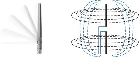
Figure 4-7 Cisco Dipole Antenna
The E and H plane radiation patterns for a typical dipole antenna are shown in Figure 4-8. In the E plane, think of the dipole lying on its side in the center of the plot; the H plane is looking down on the top of the dipole. Figure 4-9 takes the patterns a step further, showing how the two planes are superimposed and merged to reveal the three-dimensional radiation pattern.
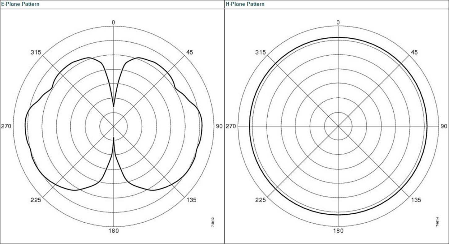
Figure 4-8 E and H Radiation Patterns for a Typical Dipole Antenna
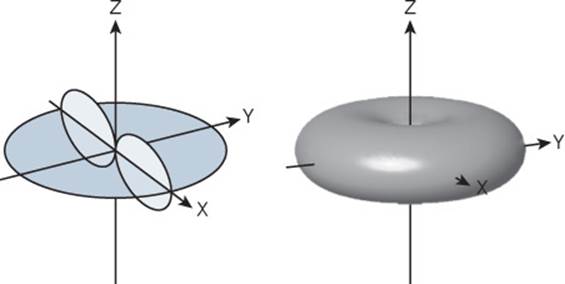
Figure 4-9 Dipole Radiation Pattern in Three Dimensions
Dipoles are often connected to wireless LAN devices that mount on the ceilings of rooms and hallways. Most dipole antennas are between 3.5 and 5.5 inches long, so they are not always aesthetically pleasing when they stick down from a ceiling. For this reason, Cisco offers several monopole antennas as an alternative.
Monopole antennas are very short—less than 2 inches in length, as shown in Figure 4-10. To achieve such a small size, they contain only one short length of wire. You can think of this as a compromised dipole antenna, where one of the antenna segments stands out away from the wireless device. The other segment is moved down into the device, in the form of a metal ground plane. Therefore, monopole antennas can be used only on devices that have a large, flat metal casing. The radiation pattern is similar to that of a dipole, but not quite as symmetrical. Monopole antennas have a typical gain of 2.2 dBi in the 2.4- and 5-GHz bands.
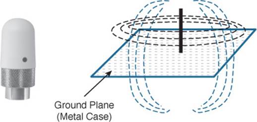
Figure 4-10 Cisco Monopole Antenna
To reduce the size of an omnidirectional antenna even further, many Cisco wireless access points (APs) have integrated antennas that are hidden inside the device’s smooth case. For example, the AP shown in Figure 4-11 has six tiny antennas hidden inside it.
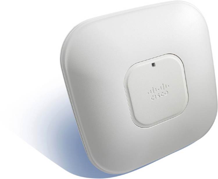
Figure 4-11 Cisco Wireless Access Point with Integrated Omnidirectional Antennas
Integrated omnidirectional antennas typically have a gain of 2 dBi in the 2.4-GHz band and 5 dBi in the 5-GHz band. The E and H plane radiation patterns are shown in Figure 4-12. When the two planes are merged, the three-dimensional pattern shown in Figure 4-13 is revealed.
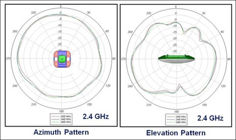
Figure 4-12 E and H Radiation Patterns for a Typical Integrated Omnidirectional Antenna
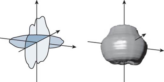
Figure 4-13 Integrated Omnidirectional Antenna Radiation Pattern in 3D
Tip
What about wireless LAN adapters that are used in mobile devices like laptops and smartphones? Because the adapters are so small, their antennas must also be tiny. As a result, USB wireless adapters often have a gain of 0 dBi, while some smartphones even have a negative gain! This does not mean that the antennas do not radiate or receive signals. Instead, the antennas just have a lower performance compared with other, larger devices.
Directional Antennas
Directional antennas have a higher gain than omnidirectional antennas because they focus the RF energy in one general direction. Typical applications include elongated indoor areas, such as the rooms along a long hallway or the aisles in a warehouse. They can also be used to cover outdoor areas out away from a building or long distances between buildings.
Patch antennas have a flat rectangular shape, as shown in Figure 4-14, so that they can be mounted on a wall.
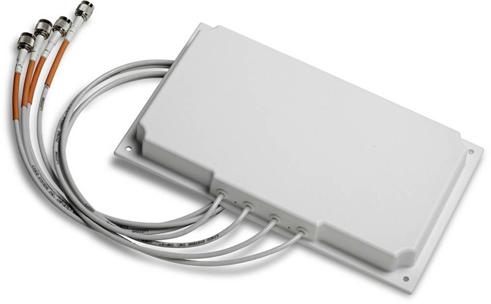
Figure 4-14 Typical Cisco Patch Antenna
Patch antennas produce a broad egg-shaped pattern that extends out away from the flat patch surface. The E and H radiation pattern plots are shown in Figure 4-15. When the planes are merged as shown in Figure 4-16, you can see the somewhat broad directional pattern that results. Patch antennas have a typical gain of about 6 to 8 dBi in the 2.4-GHz band and 7 to 10 dBi at 5 GHz.
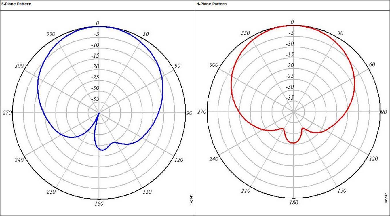
Figure 4-15 E and H Radiation Patterns for a Typical Patch Antenna
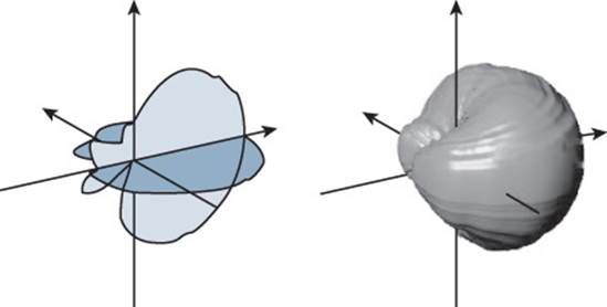
Figure 4-16 Patch Antenna Radiation Pattern in Three Dimensions
Figure 4-17 shows the Yagi-Uda antenna, named after its inventors, and more commonly known as the Yagi. Although its outer case is shaped like a thick cylinder, the antenna is actually made up of several parallel elements of increasing length.
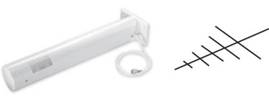
Figure 4-17 Cisco Yagi Antenna
Figure 4-18 shows the E and H radiation pattern plots. A Yagi produces a more focused egg-shaped pattern that extends out along the antenna’s length, as shown in Figure 4-19. Yagi antennas have a gain of about 10-14 dBi in the 2.4-GHz band. Cisco does not offer a 5-GHz Yagi.
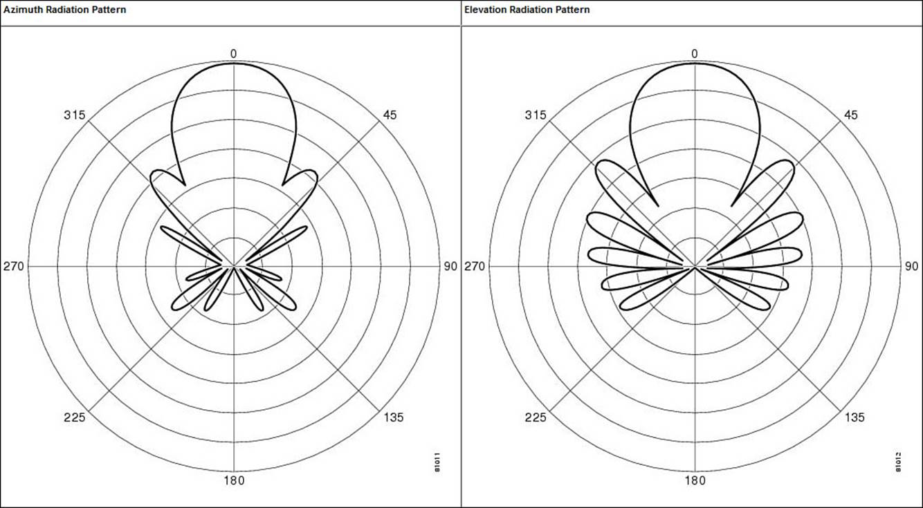
Figure 4-18 E and H Radiation Patterns for a Typical Yagi Antenna
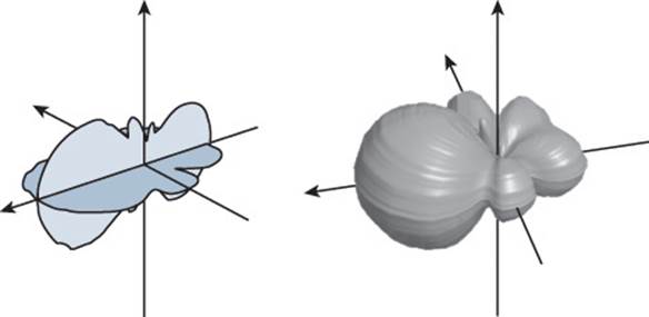
Figure 4-19 Yagi Antenna Radiation Pattern in Three Dimensions
In a line-of-sight wireless path, an RF signal must be propagated a long distance using a narrow beam. Highly directional antennas are tailored for that use, but focus the RF energy along one narrow elliptical pattern. Because the target is only one receiver location, the antenna does not have to cover any area outside of the line of sight.
Dish antennas, such as the one shown in Figure 4-20, use a parabolic dish to focus received signals onto an antenna mounted at the center. The parabolic shape is important because any waves arriving from the line of sight will be reflected onto the center antenna element that faces the dish. Transmitted waves are just the reverse; they are aimed at the dish and reflected such that they are propagated away from the dish along the line of sight.
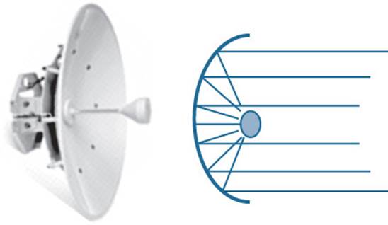
Figure 4-20 Cisco Parabolic Dish Antenna
Figure 4-21 shows the radiation patterns in the E and H planes, which are merged into three dimensions in Figure 4-22. Notice how the antenna’s coverage pattern is long and narrow, extending out away from the dish. The focused pattern gives the antenna a gain of between 20 and 30 dBi—the highest gain of all the wireless LAN antennas.
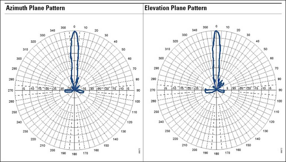
Figure 4-21 E and H Radiation Patterns for a Parabolic Dish Antenna
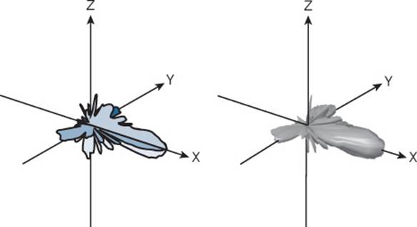
Figure 4-22 Parabolic Dish Antenna Radiation Pattern in Three Dimensions
Antenna Summary
Table 4-2 lists each antenna type and style, along with typical beamwidth and gain values. You can use this table as a summary to help compare the antennas side by side. Notice that the beamwidth is the largest for omnidirectional antennas, and then begins to narrow through the progression of directional antennas. The opposite is true of the gain—omnidirectional antennas have the lowest gain, whereas directional antennas increase gain as their beamwidth narrows.
![]()
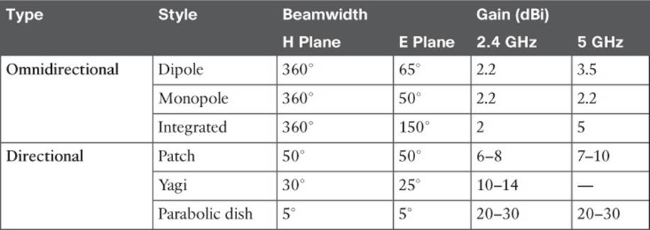
Table 4-2 Summary of Antenna Characteristics
Adding Antenna Accessories
Occasionally, you may find that you are simply not able to meet the path link budget between a transmitter and a receiver. This might be because the distance, and therefore the free space path loss, is too great. Perhaps the transmitter does not offer enough output power, or the cable connecting the transmitter to the antenna is too long or introduces too much loss. You can add an amplifier to provide additional gain, provided the EIRP does not exceed the maximum value allowed. An amplifier is an active, powered device that is connected inline between a transmitter and an antenna, as shown in Figure 4-23.
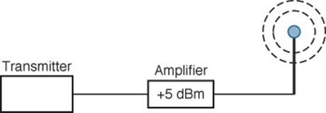
Figure 4-23 Using an Amplifier to Add 5-dBm Gain
At other times, you may need to reduce the signal strength of a transmitter beyond what is possible with the transmitter settings. For example, the transmitter may already be configured for its lowest possible transmit power level, but the signal strength is still too great for nearby receivers. You can position an attenuator, a passive device that absorbs part of the energy, inline between a transmitter and an antenna, as shown in Figure 4-24.
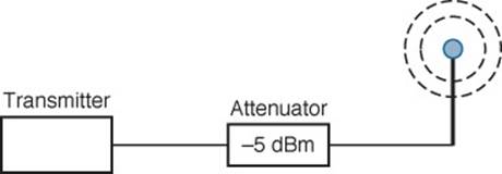
Figure 4-24 Using an Attenuator to Add 5-dBm Loss
When a transmitter or receiver is connected to an outdoor antenna, there is always the possibility that lightning will induce a tremendous amount of energy through the antenna—enough to damage the wireless LAN equipment and portions of the network. To protect against such damage, you should always connect a lightning arrestor inline between an outdoor antenna and a wireless LAN device, as shown in Figure 4-25.
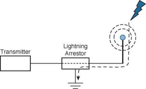
Figure 4-25 Using a Lightning Arrestor to Protect Sensitive Wireless LAN Equipment
The lightning arrestor has two connectors that attach to the two ends of coaxial cable, in addition to a grounding lug, which should connect to the nearest building or electrical ground. The RF signal is allowed to pass on through the lightning arrestor, but sudden spikes of electricity will be bypassed to ground. Contrary to its name, a lightning arrestor can never prevent the damage from a direct lightning strike. In can, however, prevent damage that might occur due to static electricity discharges or transient voltage spikes during thunderstorms.
Exam Preparation Tasks
As mentioned in the section, “How to Use This Book,” in the Introduction, you have a couple of choices for exam preparation: the exercises here, Chapter 21, “Final Review,” and the exam simulation questions on the DVD.
Review All Key Topics
Review the most important topics in this chapter, noted with the Key Topic icon in the outer margin of the page. Table 4-3 lists a reference of these key topics and the page numbers on which each is found.
![]()

Table 4-3 Key Topics for Chapter 4
Define Key Terms
Define the following key terms from this chapter and check your answers in the glossary:
amplifier
attenuator
beamwidth
dipole
directional antenna
E plane
gain
H plane
integrated antenna
lightning arrestor
monopole
omnidirectional antenna
parabolic dish antenna
patch antenna
polar plot
polarization
radiation pattern
Yagi antenna
All materials on the site are licensed Creative Commons Attribution-Sharealike 3.0 Unported CC BY-SA 3.0 & GNU Free Documentation License (GFDL)
If you are the copyright holder of any material contained on our site and intend to remove it, please contact our site administrator for approval.
© 2016-2026 All site design rights belong to S.Y.A.