CCNA Wireless 200-355 Official Cert Guide (2016)
Chapter 3. RF Signals in the Real World
This chapter covers the following topics:
![]() Interference—This section describes several types of external interference that can adversely affect a wireless signal.
Interference—This section describes several types of external interference that can adversely affect a wireless signal.
![]() Free Space Path Loss—This section explains why a radio frequency signal degrades as it travels through free space.
Free Space Path Loss—This section explains why a radio frequency signal degrades as it travels through free space.
![]() Effects of Physical Objects—This section explores what happens when an RF signal meets various physical objects, resulting in effects such as reflection, absorption, refraction, and diffraction.
Effects of Physical Objects—This section explores what happens when an RF signal meets various physical objects, resulting in effects such as reflection, absorption, refraction, and diffraction.
This chapter covers the following exam topics:
![]() 1.1—Describe the propagation of radio waves
1.1—Describe the propagation of radio waves
![]() 1.1b—Absorption, reflection, diffraction, scattering, refraction, fading, free space path loss, multipath
1.1b—Absorption, reflection, diffraction, scattering, refraction, fading, free space path loss, multipath
![]() 1.2—Interpret RF signal measurements
1.2—Interpret RF signal measurements
![]() 1.2b—Differentiate interference vs. noise
1.2b—Differentiate interference vs. noise
Radio frequency (RF) signals travel through the air as electromagnetic waves. In an ideal setting, a signal would arrive at the receiver exactly as the transmitter sent it. In the real world, this is not always the case. Many things affect RF signals as they travel from a transmitter to a receiver. This chapter explores many of the conditions that can affect wireless signal propagation.
“Do I Know This Already?” Quiz
The “Do I Know This Already?” quiz allows you to assess whether you should read this entire chapter thoroughly or jump to the “Exam Preparation Tasks” section. If you are in doubt about your answers to these questions or your own assessment of your knowledge of the topics, read the entire chapter. Table 3-1 lists the major headings in this chapter and their corresponding “Do I Know This Already?” quiz questions. You can find the answers in Appendix A, “Answers to the ‘Do I Know This Already?’ Quizzes.”
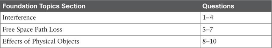
Table 3-1 “Do I Know This Already?” Section-to-Question Mapping
Caution
The goal of self-assessment is to gauge your mastery of the topics in this chapter. If you do not know the answer to a question or are only partially sure of the answer, you should mark that question as wrong for purposes of the self-assessment. Giving yourself credit for an answer you correctly guess skews your self-assessment results and might provide you with a false sense of security.
1. An 802.11 transmitter is configured to send a signal on channel 11. Someone reports a problem receiving the signal, so you investigate and find a second transmitter broadcasting on channel 11. Which one of the following best describes the problem?
a. Path interference
b. Adjacent channel interference
c. Co-channel interference
d. Cross-channel interference
2. Suppose that you place a new 802.11n transmitter in a building, but notice that there are other signals already coming from transmitters in the same general area. To avoid interference problems, how much greater should your transmitter’s signal be above all of the others to provide the best signal?
a. 0 dB
b. +3 dB
c. +5 dB
d. +10 dB
e. +20 dB
3. An existing transmitter in your office sends its signal on 2.4-GHz channel 1. Suppose that someone in a neighboring office sets up a new wireless router. He notices your signal on channel 1, so he chooses channel 2 instead. Which one of the following might adversely affect the wireless operation?
a. Co-channel interference
b. Neighboring channel interference
c. Wideband interference
d. Excessive SNR
4. Which one of the following is the best strategy for avoiding interference between neighboring channels in the 2.4-GHz band?
a. Use any channel number that seems to be available
b. Leverage 802.11n for 40-MHz aggregated channels
c. Use only channels that are spaced four numbers apart, beginning with channel 1
d. Use only channels that are spaced five numbers apart, beginning with channel 1
5. Which one of the following is the primary cause of free space path loss?
a. Spreading
b. Absorption
c. Humidity levels
d. Magnetic field decay
6. Which one of the following has the shortest effective range in free space, assuming that the same transmit power level is used for each?
a. An 802.11g device
b. An 802.11a device
c. An 802.11b device
d. None of these answers
7. Suppose that an 802.11a device moves away from a transmitter. As the signal strength decreases, which one of the following might the device or the transmitter do to improve the signal quality along the way?
a. Aggregate more channels
b. Use more radio chains
c. Switch to a more complex modulation scheme
d. Switch to a less-complex modulation scheme
8. When RF signals are reflected by objects in a building, which one of the following best describes the result that might be experienced at a receiver?
a. Fresnel loss
b. Multipath
c. Cross-channel fading
d. Free space path loss
9. Which one of the following best describes the effect that a building material has as an RF signal passes through a wall?
a. Reflection
b. Refraction
c. Diffraction
d. Absorption
e. Multipath
10. Which one of the following best describes the first Fresnel zone?
a. The area covered by one transmitter on a channel
b. The area around a signal path that should be kept clear of any obstructions
c. The area around a signal path that is blocked by the earth’s curvature
d. The area around a transmitter that represents the range of a signal
Foundation Topics
Interference
The idea behind WLAN modulation is to pack as much data as possible into the wireless signal, and to minimize the amount of data that might be lost due to interference or noise. When data is lost, it must be retransmitted, using more of the wireless resources. Therefore, it is always best if a transmitter is configured to use a channel that is open and is clear from any other transmitter.
Co-Channel Interference
Whenever one transmitter’s signal overlaps another on a frequency or channel, the signals interfere with each other. Interference can be described by the way the signals overlap. For example, co-channel interference occurs when two or more transmitters use the same channel. In Figure 3-1, Transmitters A and B are both transmitting an RF signal on channel 6 in the 2.4-GHz band.
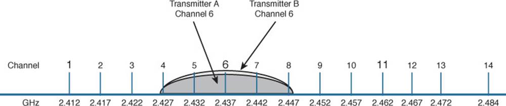
Figure 3-1 Co-Channel Interference
Because the two 802.11 transmitters are using the same channel, their signals completely overlap and the whole 22-MHz channel bandwidth is affected. This might not be a problem if the transmitters are not sending data at the same time. After all, wireless LAN devices must contend for use of the airtime; if nobody is transmitting at a given time, someone may use the channel.
When both transmitters are busy sending data, the channel can become very congested. The two signals begin to interfere and cause data corruption, which causes devices to retransmit lost data, which uses more airtime, and so on.
In the real world, co-channel interference is often a necessary evil. The 2.4-GHz band offers only three non-overlapping channels. If you have many transmitters in a building or area, you are bound to have some of them transmitting on the same channel as others. The best solution is to use careful planning when you select the channel for each transmitter. For instance, two nearby transmitters should never be placed on the same channel because their strong signals would be more likely to interfere.
Instead, a transmitter should only share a channel with other distant transmitters whose received signals are much weaker. A best practice is to place a transmitter on a channel only if its signal will be stronger than any other received signal by some margin. A common margin is at least 19 dB, as shown in Figure 3-2.
![]()
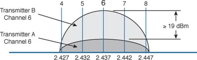
Figure 3-2 Maintaining Signal Separation to Minimize Co-Channel Interference
Having at least 19-dB separation helps maintain a healthy signal-to-noise ratio (SNR) in the area surrounding the transmitter. Be aware that this margin differs according to the modulation and coding scheme that is in use. For example, simple BPSK modulation may need less than 10 dB, while 19 dB may be enough to support 64-QAM modulation (54 Mbps) for 802.11g or 802.11a. The 256-QAM modulation used in 802.11ac requires much more—anywhere from 31 to 50 dB!
Note
Channel assignment is covered in more detail in Chapter 7, “Planning Coverage with Wireless APs.”
Neighboring Channel Interference
Suppose that two transmitters are placed on two different channels. However, the channels are spaced too closely together such that they overlap each other. Perhaps someone decided to use neighboring channels, rather than reuse the same channel, to avoid co-channel interference. More likely, two different people have transmitters located in the same general area and decided to use slightly different channel numbers—not realizing that neighboring channels in the 2.4-GHz band overlap.
The end result is interference on both channels because a portion of one signal overlaps a portion of another signal. In Figure 3-3, transmitter A is using channel 6, while transmitter B is using channel 7. The two signals do not completely overlap, but the interference between them is enough to be detrimental to both.
Figure 3-3 Adjacent Channel Interference
Tip
Do you think of neighboring channels as having adjacent channel numbers? You are not alone; after all, channel numbers 1 and 2 are adjacent. Interference between neighboring channels is commonly called adjacent channel interference. Technically, this term is incorrect and is often misused. The 802.11 standard defines adjacent channels as non-overlapping channels. Therefore, by definition, it is impossible for adjacent channels to overlap and interfere. Be aware that the CCNA Wireless exam strictly uses the terminology found in the 802.11 standard. Adjacent channels cannot overlap, but neighboring channels can.
To remedy the situation, all transmitters in an area should be configured to use the three non-overlapping 2.4-GHz channels: 1, 6, and 11. In the 5-GHz band, adjacent channel interference is not a problem because the channels do not significantly overlap; the channels are 20 MHz wide, whereas the orthogonal frequency-division multiplexing (OFDM) signals have a bandwidth of 20 MHz. As a best practice, you should still avoid placing neighboring access points on neighboring 5-GHz channels, just to avoid the possibility of raising the noise floor.
Non-802.11 Interference
Recall that the 2.4-GHz band is an ISM band. This means that your 802.11 wireless LAN devices might share the same frequency space as non-802.11 devices. That might not sound like a bad situation because the devices could simply be configured to use different, non-overlapping channels.
In practice, such an elegant solution might not be possible. Many non-802.11 devices do not sit on any one channel; they use frequency-hopping spread spectrum (FHSS) to hop around on a variety of channels at any given time. Even worse, some devices do not adhere to any channel scheme at all. Figure 3-4 shows transmitters A, B, and C using channels 1, 6, and 11, which is a perfect world—until someone decides to warm up her lunch. A nearby microwave oven also uses RF energy in the 2.4-GHz ISM band to radiate the food. Because it is poorly shielded, the RF energy escapes and interferes with most of the 802.11b/g channels nearby. The microwave’s transmission is also constant, rendering the wireless LAN channels mostly useless.
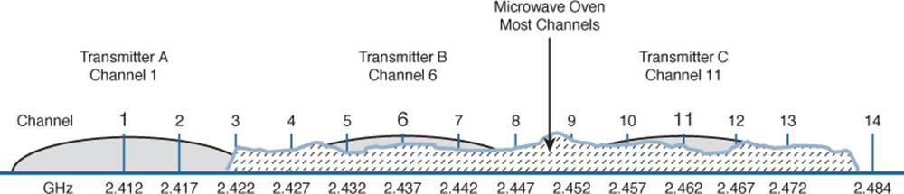
Figure 3-4 Non-802.11 Interference from a Microwave Oven
To mitigate interference from non-802.11 devices, you have to eliminate the source. Leaky microwave ovens should be replaced with better models that have proper RF shielding. Devices like 2.4-GHz FHSS cordless phones or wireless video cameras should be replaced with models that operate in a non-802.11 band.
Note
Noise and interference are topics that are covered in more detail in Chapter 19, “Dealing with Wireless Interference.”
Free Space Path Loss
Whenever an RF signal is transmitted from an antenna, its amplitude decreases as it travels through free space. Even if there are no obstacles in the path between the transmitter and receiver, the signal strength will weaken. This is known as free space path loss.
What is it about free space that causes an RF signal to be degraded? Is it the air or maybe the earth’s magnetic field? No, even signals sent to and from spacecraft in the vacuum of outer space are degraded.
Recall that an RF signal propagates through free space as a wave, not as a ray or straight line. The wave has a three-dimensional curved shape that expands as it travels. It is this expansion or spreading that causes the signal strength to weaken.
Figure 3-5 shows a cutaway view of the free space loss principle. Suppose the antenna is a tiny point, such that the transmitted RF energy travels in every direction. The wave that is produced would take the form of a sphere; as the wave travels outward, the sphere increases in size. Therefore, the same amount of energy coming out of the tiny point is soon spread over an ever expanding sphere in free space. The concentration of that energy gets weaker as the distance from the antenna increases.
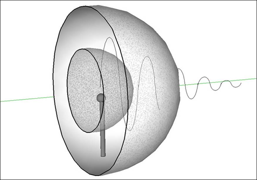
Figure 3-5 Free Space Loss Due to Wave Spreading
Even if you could devise an antenna that could focus the transmitted energy into a tight beam, the energy would still travel as a wave and would spread out over a distance. Regardless of the antenna used, the amount of signal strength loss is consistent.
The free space path loss (FSPL) in dB can be calculated according to the following equation:
FSPL (dB) = 20log10(d) + 20log10(f) + 32.44
where d is the distance from the transmitter in kilometers and f is the frequency in megahertz. Do not worry, though: you will not have to know this equation for the CCNA Wireless exam. It is presented here to show two interesting facts:
![]() Free space path loss is an exponential function; the signal strength falls off quickly near the transmitter, but more slowly farther away.
Free space path loss is an exponential function; the signal strength falls off quickly near the transmitter, but more slowly farther away.
![]() The loss is a function of distance and frequency only.
The loss is a function of distance and frequency only.
With the formula, you can calculate the free space path loss for any given scenario, but you will not have to for the exam. Just be aware that the free space path loss is always an important component of the link budget, along with antenna gain and cable loss.
You should also be aware that the free space path loss is greater in the 5-GHz band than it is in the 2.4-GHz band. In the equation, as the frequency increases, so does the loss in dB. This means that 802.11b/g/n devices (2.4 GHz) have a greater effective range than 802.11a/n (5 GHz) devices, assuming an equal transmitted signal strength. Figure 3-6 shows the range difference, where both transmitters have an effective isotropic radiated power (EIRP) of 14 dBm and the effective range ends where a receiver’s received signal strength indicator (RSSI) equals –67 dBm.
![]()
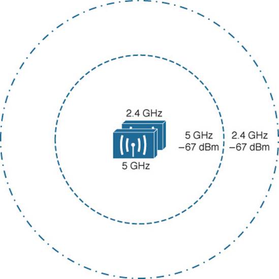
Figure 3-6 Effective Range of 2.4-GHz and 5-GHz Transmitters
Tip
To get a feel for the actual range difference between 2.4 and 5 GHz, a receiver was carried away from the two transmitters until the RSSI reached –67 dBm. On a 2.4-GHz channel, the range was measured to be 140 feet, whereas at 5 GHz it was reduced to 80 feet. While the free space path loss is the largest contributor to the difference, other factors like antenna size and receiver sensitivity that differ between the 2.4 and 5 GHz radios have some effect, too.
Mitigating the Effects of Free Space Path Loss
One simple solution to overcome free space path loss is to increase the transmitter’s output power. Increasing the antenna gain can also boost the EIRP. Having a greater signal strength before the free space path loss occurs translates to a greater RSSI value at a distant receiver after the loss. This approach might work fine for an isolated transmitter, but can cause interference problems when several transmitters are located in an area.
A more robust solution is to just cope with the effects of free space path loss. Wireless devices are usually mobile and can move closer to or farther away from a transmitter at will. As a receiver gets closer to a transmitter, the RSSI increases. This, in turn, translates to an increased SNR. Recall from Chapter 1, “RF Signals and Modulation,” that more complex modulation and coding schemes can be used to transport more data when the SNR is high. As a receiver gets farther away from a transmitter, the RSSI (and SNR) decreases. More basic modulation and coding schemes are needed there because of the increase in noise and the need to repeat more data.
802.11 devices have a clever way to adjust their modulation and coding schemes based on the current RSSI and SNR conditions. If the conditions are favorable for good signal quality and higher data rates, a complex modulation and coding scheme is used. As the conditions deteriorate, less-complex schemes can be selected, resulting in a greater range but lower data rates. The scheme selection is commonly known as dynamic rate shifting (DRS). As its name implies, it can be performed dynamically with no manual intervention.
Tip
Although DRS is inherently used in 802.11 devices, it is not defined in the 802.11 standard. Each manufacturer can have its own approach to DRS; so all devices don’t necessarily select the same scheme at the same location. DRS is also known by many alternative names, such as link adaptation, adaptive modulation and coding (AMC), rate adaptation, and so on.
Figure 3-7 illustrates DRS operation on the 2.4-GHz band. Each concentric circle represents the range supported by a particular modulation and coding scheme. The figure is somewhat simplistic because it assumes a consistent power level across all modulation types. Notice that the white circles denote OFDM modulation (802.11g) and that the shaded circles contain DSSS modulation (802.11b). None of the 802.11n modulation types are shown, for simplicity. The data rates are arranged in order of increasing circle size or range from the transmitter.
![]()
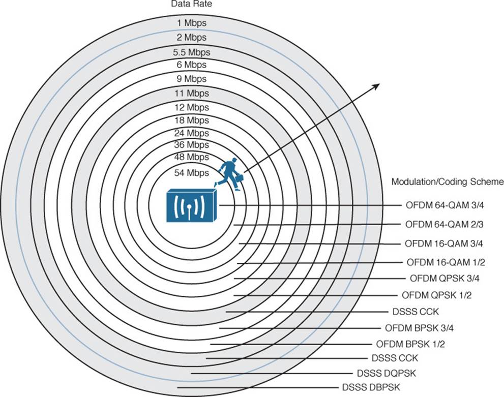
Figure 3-7 Dynamic Rate Shifting as a Function of Range
Suppose that a mobile user starts out near the transmitter, within the innermost circle, where the received signal is strong and SNR is high. Most likely, wireless transmissions will use the OFDM 64-QAM 3/4 modulation and coding scheme to achieve a data rate of 54 Mbps. As the user walks away from the transmitter, the RSSI and SNR fall by some amount. The new RF conditions will likely trigger a shift to a different modulation and coding scheme, resulting in a lower data rate.
In a nutshell, each move into a larger concentric circle causes a dynamic shift to a reduced data rate, in an effort to maintain the data integrity to the outer reaches of the transmitter’s range.
The 5-GHz band looks very similar to Figure 3-7, except that every circle uses an OFDM modulation scheme corresponding to 802.11a, 802.11n, or 802.11ac.
Effects of Physical Objects
As an RF signal propagates through free space, it might encounter physical objects in its path. Objects and materials can affect an RF signal in a variety of ways, mostly in a degrading or destructive fashion. The following sections cover the most common scenarios.
Reflection
If an RF signal traveling as a wave meets a dense reflective material, the signal can be reflected. Think of the light emitted from a light bulb; while most of the light is traveling in all directions away from the bulb, some might be reflected from objects in a room. The reflected light might travel back toward the bulb or toward another area of the room, making that area even brighter.
Figure 3-8 depicts a reflected RF signal. Indoor objects such as metal furniture, filing cabinets, and metal doors can cause reflection. An outdoor wireless signal can be reflected by objects such as a body of water, reflective glass on a building, or the surface of the earth.
![]()
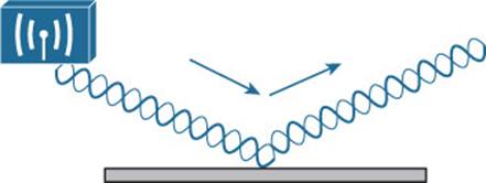
Figure 3-8 Reflection of an RF Signal
A reflection is not necessarily bad, because it is just a copy of the original signal. However, if both the copy and the original reach a receiver, they can arrive out of phase with each other. This is because the reflection takes a different path than the original, causing it to arrive slightly later. This is known as multipath. When the receiver combines the two signals, the result is a poor representation of the original signal. The combined signal can be weak and distorted, causing the data to be corrupted.
In Figure 3-9, the original signal, along with two different reflections, arrive at the receiver embedded in a laptop computer. The two reflections each take a different path and arrive at different times.
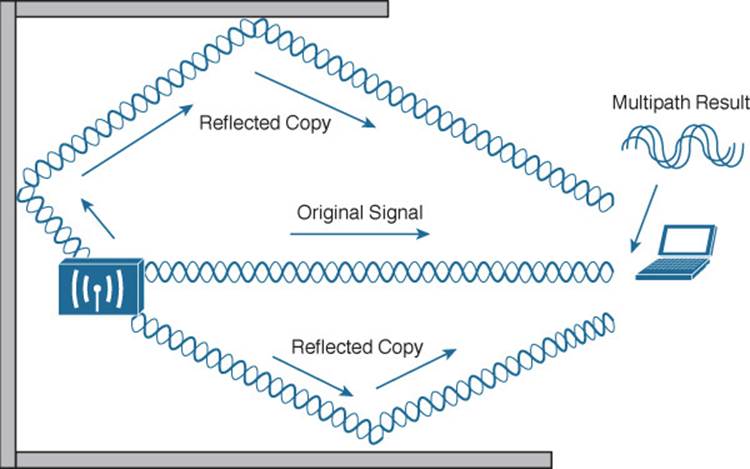
Figure 3-9 Multipath Transmissions
When multipath transmissions occur, there can be two outcomes:
![]() If the receiver has a single radio chain, then all of the arriving signals (original and reflected) are combined into one poor, error prone composite signal.
If the receiver has a single radio chain, then all of the arriving signals (original and reflected) are combined into one poor, error prone composite signal.
![]() If the receiver has multiple radio chains and supports multiple-input, multiple-output (MIMO), each arriving signal will be received on each of the different antennas and radios. Further processing can improve the signal quality to extract the multiple data streams—making something good out of a bad situation.
If the receiver has multiple radio chains and supports multiple-input, multiple-output (MIMO), each arriving signal will be received on each of the different antennas and radios. Further processing can improve the signal quality to extract the multiple data streams—making something good out of a bad situation.
Absorption
If an RF signal passes into a material that can absorb some of its energy, the signal will be attenuated. The more dense the material, the more the signal will be attenuated. Figure 3-10 shows how a signal is affected by absorption and how a receiver might be affected by the lower signal strength.
![]()
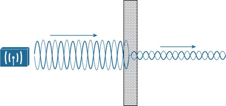
Figure 3-10 Absorption of an RF Signal
One common example of absorption is when a wireless signal passes through a wall in a building. Different wall materials absorb different amounts of energy. For example, a wall constructed from gypsum or drywall might attenuate a signal by –4 dBm. A solid concrete wall might attenuate it by –12 dBm. The thicker the wall or the more dense the material, the greater the attenuation will be.
In outdoor wireless scenarios, RF signals frequently have to travel through water. The water might be contained in tree leaves positioned along the wireless path. Even in unobstructed space, the signal might encounter water in the form of rain, snow, hail, or fog. As the air is filled with heavier rain or snow, the signal will be attenuated more. Because weather conditions change over time, an RF signal will be attenuated accordingly—a strong signal on a clear day can fade or become weaker on rainy days.
Another less-obvious example of absorption is the human body, which is made up mostly of water. A person will usually hold a laptop computer, tablet PC, or a smartphone close to his or her body. Depending on how the person is oriented with respect to the transmitter, his body could sit between the transmitter and the receiver, attenuating the signal. For example, a hand covering a phone antenna can decrease a received signal by 6–8 dB; a person’s head might attenuate the signal received by a phone antenna by almost 30 dB. Likewise, a classroom or auditorium might be filled with human bodies, each with the potential to attenuate the signal from a transmitter.
Tip
To gain perspective, a quick experiment revealed that a human body attenuated a 2.4-GHz signal by –5 dBm.
Scattering
When an RF signal passes into a medium that is rough, uneven, or made up of very small particles, the signal can be scattered into many different directions. This is because the tiny irregular surfaces of the medium can reflect the signal, as shown in Figure 3-11. Scattering can occur when a wireless signal passes through a dusty or sandy environment.
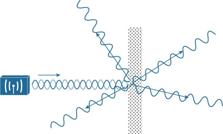
Figure 3-11 Scattering an RF Signal
Refraction
When an RF signal meets the boundary between media of two different densities, it can also be refracted. Think of reflection as bouncing off a surface and refraction as being bent while passing through a surface.
A refracted signal will have a different angle from the original, as illustrated in Figure 3-12. The speed of the wave can also be affected as it passes through the different materials. A signal can be refracted when it passes through layers of air having different densities or through building walls with different densities, for example.
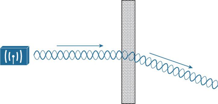
Figure 3-12 Refraction of an RF Signal
Diffraction
Suppose an RF signal approaches an opaque object, or one that is able to absorb the energy that strikes it. You might think that the object would produce a shadow in place of the signal that is absorbed, much like an object might make a shadow as light shines on it. If a shadow formed, it might make a dead or silent zone in the RF signal behind the object.
With RF propagation, however, the signal tends to bend around the object and eventually rejoin to complete the wave. Figure 3-13 shows how a radio-opaque object can cause diffraction of an RF signal. Diffraction is best viewed as concentric waves, rather than an oscillating signal, so that its effect on the actual waves can be seen. In the figure, diffraction has caused the signal to “heal” itself around an absorbing object. This makes reception possible even when a building stands between the transmitter and receiver. However, the signal is never quite like the original again, as it has been distorted by the diffraction.
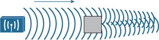
Figure 3-13 Diffraction of an RF Signal
Fresnel Zones
If an object is standing free, so that an RF signal traveling parallel with the ground is diffracted around it on both sides, the signal will often fill in the object’s “shadow” as it continues to propagate. However, if a standing object such as a building or a mountain obstructs the signal, the signal can be adversely affected in the vertical direction.
In Figure 3-14, a building partially obstructs the path of the signal. Because of diffraction along the front and top of the building, the signal is bent and also attenuated. This causes the signal to be masked behind most of the height of the building.
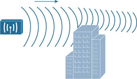
Figure 3-14 Standing Obstacle Diffracts a Signal
This is especially important in narrow line-of-sight wireless transmission, which is suited for very long distances. These signals do not propagate in all directions; rather, they are focused into a tight cone-shaped pattern, as shown in Figure 3-15. For a line-of-sight path, the signal must be clear of any obstructions between the transmitter’s antenna and the receiver’s antenna. Paths between buildings or between cities commonly have other buildings, trees, or other objects that might block the signal. In those cases, the antennas must be raised higher than the obstructions to get a clear path.
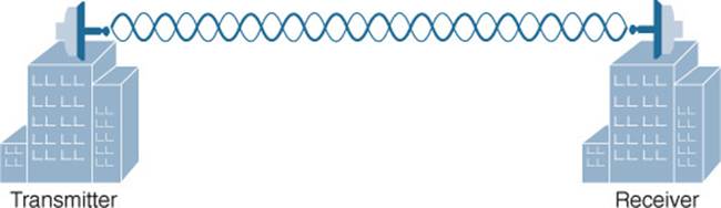
Figure 3-15 Line-of-Sight Wireless Signal
Over a very long distance, the curvature of the earth actually becomes an obstacle that can affect the signal. At ground level, beyond a distance of about two miles, the far end cannot be seen because it lies slightly below the horizon. Nevertheless, a wireless signal tends to propagate along the same curve, following the atmosphere around the earth’s curvature.
Even narrow line-of-sight signals can be affected by diffraction, even if an object does not directly block the signal. There is an elliptical-shaped volume around the line of sight that must also remain free of obstructions. This is called the Fresnel zone, as shown in Figure 3-16. If an object penetrates the Fresnel zone anywhere along the path, some portion of the RF signal can be diffracted by it. That portion of the signal gets bent, causing it to be delayed or altered so that it affects the overall signal arriving at the receiver.
![]()
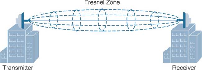
Figure 3-16 Fresnel Zone
Tip
Actually, there are many concentric Fresnel zones surrounding the line-of-sight path. Only the innermost, or first, Fresnel zone is described in this section and taken into account because it affects the transmitted signal the most. Fresnel zones are numbered incrementally as their size increases. Oddly enough, the odd-numbered Fresnel zones have a destructive effect on signals, whereas the even-numbered zones can have a constructive effect and add to the signal’s power.
In Figure 3-17, a building lies along the signal’s path, but does not obstruct the beam of the signal; however, it does penetrate the Fresnel zone, so the received signal will be negatively affected.
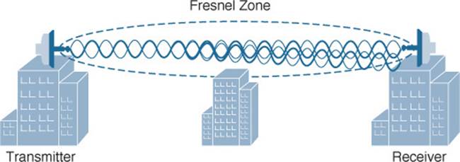
Figure 3-17 Signal Degradation Due to a Fresnel Zone Obstruction
As a rule, you should raise the antennas of a line-of-sight system so that even the bottom of the Fresnel zone is higher than any obstruction. Remember that as the path gets very long, even the curvature of the earth can enter the Fresnel zone and cause problems, as Figure 3-18 shows.
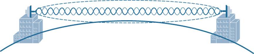
Figure 3-18 Earth’s Curvature Enters the Fresnel Zone
The radius of the Fresnel zone can be calculated according to a complex formula. However, you should only be concerned with the idea that the Fresnel zone exists and should remain clear. Table 3-2 gives some example values of the Fresnel zone radius at the midpoint of some line-of-sight path lengths for wireless frequencies in the 2.4-GHz band.
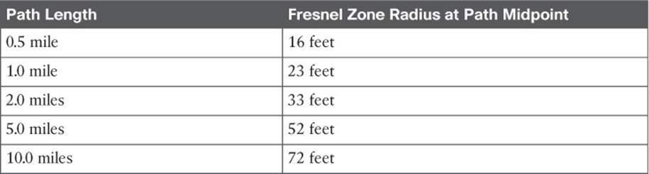
Table 3-2 Fresnel Zone Radius Values
Exam Preparation Tasks
As mentioned in the section, “How to Use This Book,” in the Introduction, you have a couple of choices for exam preparation: the exercises here, Chapter 21, “Final Review,” and the exam simulation questions on the DVD.
Review All Key Topics
Review the most important topics in this chapter, noted with the Key Topic icon in the outer margin of the page. Table 3-3 lists a reference of these key topics and the page numbers on which each is found.
![]()
Table 3-3 Key Topics for Chapter 3
Define Key Terms
Define the following key terms from this chapter and check your answers in the glossary:
absorption
adjacent channel interference
co-channel interference
diffraction
dynamic rate shifting
free space path loss
Fresnel zone
multipath
reflection
refraction
scattering
All materials on the site are licensed Creative Commons Attribution-Sharealike 3.0 Unported CC BY-SA 3.0 & GNU Free Documentation License (GFDL)
If you are the copyright holder of any material contained on our site and intend to remove it, please contact our site administrator for approval.
© 2016-2026 All site design rights belong to S.Y.A.